EP1245464A2 - Sitzrückenlehnenrahmen für Fahrzeugsitz - Google Patents
Sitzrückenlehnenrahmen für Fahrzeugsitz Download PDFInfo
- Publication number
- EP1245464A2 EP1245464A2 EP02251770A EP02251770A EP1245464A2 EP 1245464 A2 EP1245464 A2 EP 1245464A2 EP 02251770 A EP02251770 A EP 02251770A EP 02251770 A EP02251770 A EP 02251770A EP 1245464 A2 EP1245464 A2 EP 1245464A2
- Authority
- EP
- European Patent Office
- Prior art keywords
- seatback
- frame
- belt
- seat
- side bracket
- Prior art date
- Legal status (The legal status is an assumption and is not a legal conclusion. Google has not performed a legal analysis and makes no representation as to the accuracy of the status listed.)
- Granted
Links
Images


Classifications
-
- B—PERFORMING OPERATIONS; TRANSPORTING
- B60—VEHICLES IN GENERAL
- B60N—SEATS SPECIALLY ADAPTED FOR VEHICLES; VEHICLE PASSENGER ACCOMMODATION NOT OTHERWISE PROVIDED FOR
- B60N2/00—Seats specially adapted for vehicles; Arrangement or mounting of seats in vehicles
- B60N2/68—Seat frames
- B60N2/688—Particular seat belt attachment and guiding
-
- B—PERFORMING OPERATIONS; TRANSPORTING
- B60—VEHICLES IN GENERAL
- B60N—SEATS SPECIALLY ADAPTED FOR VEHICLES; VEHICLE PASSENGER ACCOMMODATION NOT OTHERWISE PROVIDED FOR
- B60N2/00—Seats specially adapted for vehicles; Arrangement or mounting of seats in vehicles
- B60N2/68—Seat frames
- B60N2/682—Joining means
-
- B—PERFORMING OPERATIONS; TRANSPORTING
- B60—VEHICLES IN GENERAL
- B60R—VEHICLES, VEHICLE FITTINGS, OR VEHICLE PARTS, NOT OTHERWISE PROVIDED FOR
- B60R22/00—Safety belts or body harnesses in vehicles
- B60R22/18—Anchoring devices
- B60R22/26—Anchoring devices secured to the seat
Definitions
- the present invention relates to a seatback frame for a vehicle seat and, more particularly, to a seatback frame for a vehicle seat equipped with a seat belt of the three-point type wherein a retractor for winding a seat belt is mounted at a lower portion of the seatback and allows a shoulder belt to be pulled out for restraining a seat occupant, a belt-through member is mounted at an upper distal end of the seatback for guiding the shoulder belt, fixture segments are mounted at both sides of a seat cushion for supporting both ends of a lap belt which restrains the waist of the seat occupant, and a distal end of the shoulder belt is supported with one of the fixture segments.
- seat belts in practical use are divided into two types, a first type in which a retractor is fixedly mounted to a pillar of a vehicle body and a second type in which the retractor is directly fixed to a seatback frame.
- the seat belt in normal use is constructed of a lap belt portion for restraining the waist of a seat occupant and a shoulder belt portion for restraining an area covering the shoulder and the waist of the seat occupant, which are arranged in a three-point support structure which includes lap anchor points located at both sides of a seat cushion and a shoulder anchor point located at an upper distal end of a seatback.
- the seatback frame 1 is comprised of a pipe frame 2 which is shaped to conform along an external shape of a seatback, and a tower frame 3 on which a belt-through member (not shown) for a shoulder anchor point is mounted.
- a cross member 4 is obliquely placed so as to extend between an upper distal end of the tower frame 3 and a bracket 2a opposed thereto and welded to both of these components.
- the cross member 4 located so as to extend from the upper distal end of the tower frame 3 toward the opposing side portion of the seatback frame for reinforcement has an increased weight, providing a degraded operability during a reclining operation of the seatback.
- the presence of the cross member 4 obliquely located in a substantially central area of the seatback so as to cross over the same encounters a difficulty in enhancing a space for locating an active-type headrest (which is of the type wherein when exerted with impact shocks, lower distal ends of the headrest stays are urged rearward to cause the headrest to move forward for thereby preventing the head of the seat occupant from being swayed rearward to protect the same).
- an active-type headrest which is of the type wherein when exerted with impact shocks, lower distal ends of the headrest stays are urged rearward to cause the headrest to move forward for thereby preventing the head of the seat occupant from being swayed rearward to protect the same.
- an active-type headrest which is of the type wherein when exerted with impact shocks, lower distal ends of the headrest stays are urged rearward to cause the headrest to move forward for thereby preventing the head of the seat occupant from being swayed rearward
- the tower frame 3 is exerted with the impact load and, so, is required to have the structure reinforced in forward and rearward directions.
- a reinforced structure using the cross member 4 although a rigidity is provided in structure in a widthwise direction of a vehicle body, a relatively unsatisfied result takes place in the presence of the impact shocks imparted in the forward and rearward directions of the vehicle body.
- a seatback frame for a vehicle seat having a seatback and a seat cushion and equipped with a seat belt of a three-point type, wherein a retractor is mounted at a lower portion of the seatback to wind up the seat belt, a belt-through member is mounted at an upper distal end of the seatback to guide a shoulder belt of the seat belt, which is pulled out from the retractor, so as to restrain a shoulder portion of a seat occupant, both ends of a lap belt of the seat belt, which restrain a waist portion of the seat occupant, are supported with fixed portions located at both sides of the seat cushion, and a distal end of the shoulder belt is further supported with one of the fixed portions.
- the seatback frame is provided with: a pipe frame formed along an external shape of the seatback; and a vertically extending tower frame located in the seatback at the same side as the belt-through member and fixedly connected to the pipe frame.
- the tower frame includes an outer side bracket, an inner side bracket, both of which are formed of vertically extending, elongated metal sheets each formed in a substantially C-shaped cross section and both of which are coupled to one another in abutting engagement with one another to form an internal space, and an intermediate brace member incorporated in the internal space to provide a reinforcement rib structure.
- a vehicle seat is provided with: a seatback; a seat cushion; a seat belt of a three-point type, wherein a retractor is mounted at a lower portion of the seatback to wind up the seat belt, a belt-through member is mounted at an upper distal end of the seatback to guide a shoulder belt of the seat belt, which is pulled out from the retractor, so as to restrain a shoulder portion of a seat occupant, both ends of a lap belt of the seat belt, which restrain a waist portion of the seat occupant, are supported with fixed portions located at both sides of the seat cushion, and a distal end of the shoulder belt is further supported with one of the fixed portions; and a seatback frame.
- the seatback frame is provided with: a pipe frame formed along an external shape of the seatback; and a vertically extending tower frame located in the seatback at the same side as the belt-through member and fixedly connected to the pipe frame.
- the tower frame includes an outer side bracket, an inner side bracket, both of which are formed of vertically extending, elongated metal sheets each formed in a substantially C-shaped cross section and both of which are coupled to one another in abutting engagement with one another to form an internal space, and an intermediate brace member incorporated in the internal space to provide a reinforcement rib structure.
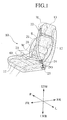
- FIG. 1 is a perspective view of the vehicle seat employing the seatback frame according to the present invention.
- FIG. 2 is a perspective view illustrating a structure of the seatback according to the present invention.
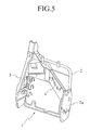
- FIG. 3 is an exploded perspective view illustrating a structure of a tower frame which forms the seatback frame shown in FIG. 3.
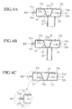
- FIGS. 4A, 4B and 4C are cross sectional views illustrating the tower frame, shown in FIG. 3, in conjunction with associated component parts shown in FIG. 2.
- FIGS frontward and rearward directions of a vehicle body are respectively represented by arrows FR and RR, rightward and leftward directions of the vehicle body are respectively represented by arrows R and L, upward and downward directions of the vehicle body are respectively represented by arrows UPR and LWR, and a right side front seat is typically illustrated.
- the vehicle seat 10 is equipped with a seat belt of a three-point support type and includes a seat cushion 11 on which a seat occupant seats, a seatback 12 standing upright from a rear distal end of the seat cushion 11 through a reclining mechanism operatively coupled to the seat cushion 11 and the seatback 12 permitting the seatback 12 to be adjusted in a reclined state at a given angular position, and a headrest 13 fixedly located at an upper edge of the seatback 12 for supporting an head H of a seat occupant.
- a seat belt equipped in the vehicle seat 10 is comprised of a retractor 20 internally incorporated in a lower side portion of the seatback 12 and fixedly secured to the vehicle body side, and a shoulder belt 21 with its one lowest end portion stored in the retractor 20 and having an intermediate portion passing through a belt-through member 22 fixedly secured to an upper distal end of the seat back 12.
- the seat occupant pulls out the shoulder belt 21 downward in an oblique direction through the belt-through member 22 so as to restrain a shoulder S of the seat occupant.
- the seat belt includes a lap belt 23 with its one end stored in a retractor 60, which is fixedly secured to the vehicle body side at a lower side of the seat cushion 11, to allow free movement of the lap belt 23 for restraining a waist W of the seat occupant, with the other end of the lap belt 23 being firmly connected to a lower distal end of the shoulder belt 21.
- a coupling tongue 24 which can be fixedly coupled to a release buckle 25 fixedly mounted to the other side of the seat cushion 11, providing a three-point support structure wherein the shoulder belt 21 and the lap belt 23, which form a waving configuration of the seat belt, are supported at a fixed point lying on the belt-through member 22, located at the upper distal end of the seatback 12, and at two fixed points lying on both sides of the seat cushion 11.
- a pulling-out direction of the shoulder belt 21 and the lap belt 23 is designated by an arrow PO.
- the retractor 60 can be replaced with a pivotably fixed member. In such a simple structure, an end of the lap belt 23 opposed to the coupling tongue 24 is simply connected to the pivotably fixed member and not wound around to be elongated.
- FIG. 2 shows a structure of the seatback frame 30 of the seatback 12.
- the seatback frame 30 is formed by bending a pipe material and is generally comprised of a substantially L-shaped pipe frame 40 and a tower frame 50 located at one side of the seatback 12 and vertically extending to provide a reinforced rigid structure.
- the pipe frame 40 includes a horizontally extending upper pipe component 41, a side pipe component 42 which is laterally spaced from the tower frame 50, and a horizontally extending lower pipe component 43. These components are so shaped as to conform to an upper edge, one of side edges and a lower edge, respectively, which form three sides of an external shape of the seatback 12.
- a side bracket 44 is fixedly secured to a lower distal end of the side pipe component 42 by some suitable means such as welding.
- Located below the upper pipe component 41 is a center pipe component 45 which transversely extends between the side pipe component 42 and the tower frame 50 to reinforce the structure of the seatback frame 30.
- S-shaped springs 46 are supported between the side pipe component 42 and the tower frame 50. Also, the upper pipe component 41 of the pipe frame 40 has a pair of guide sleeves 47 fixedly connected thereto by welding for receiving stays 13a, 13a of the headrest 13.
- the retractor 20 is received in a joined area between one end of the lower pipe component 43 of the pipe frame 40 and a lower distal end of the tower frame 50 and is fixedly secured to a pair of brackets 26, 27, fastened to the lower pipe component 43 by a welding, by tightening screws 28.
- a recliner 14 which forms the reclining mechanism discussed above, is fixedly coupled to a lower and side wall of the tower frame 50 by fixture bolts 14a.
- an important feature of the seatback frame 30 of the present invention concerns a capability of contributing to a reduction in weight and an increase in rigidity in structure to have a strength sufficient for resisting impact shocks exerted to the seatback 12 during a collision of a vehicle while adequately enhancing a space permitting free movement of an active-type headrest 13 having an impact shock absorbing ability.
- the tower frame 50 is constructed of an outer side bracket 51 formed of a vertically extending, elongated metal sheet, an inner side bracket 52 formed of a vertically extending, elongated metal sheet, and an intermediate, elongated brace member 53 with a reinforcement rib function which is interposed between the outer and inner side brackets 51, 52.
- reference numeral 54 designates a cap and bracket to be coupled to an upper opening of the tower frame 50.
- each of the outer side bracket 51 and the inner side bracket 52 has a substantially C-channeled configuration in cross section.
- the outer and inner side brackets 51, 52 have their front edges formed with front flanges 51a, 52a, respectively.
- rear sections of the outer side bracket 51 and the inner side bracket 52 are formed with vertically extending, elongated rear walls 51b, 52b.
- the intermediate brace member 53 is composed of a vertically extending, elongated central top wall 53a, a pair of elongated longitudinal wall segments 53b, 53b bent sideward from both sides of the top wall 53a, and vertically extending, elongated front and rear flanges 53c, 53c which extends from front and rear edges of the respective longitudinal wall segments 53b, 53b in forward and rearward directions of the seatback 12.
- FIGS. 4A to 4C which show the relationships among the outer side bracket 51, the inner side bracket 52 and the intermediate brace member 53, the rear walls 51b and 52b formed along the rear sections of the outer side bracket 51 and the inner side bracket 52, respectively, have overlapped margin 55, extending in a vertical direction, at which the rear walls 51b and 52b are joined to one another with suitably spaced welding intervals by some suitable welding means such as CO 2 welding.
- the front flanges 51a, 52a formed along the front edges of the outer side bracket 51 and the inner side bracket 52, respectively, are held in mating engagement with one another and are fixedly joined to one another with suitably spaced welding intervals by some suitable welding means from the vertical direction such as spot welding.
- some suitable welding means from the vertical direction such as spot welding.
- any unbalances present in a mated condition between the both side brackets can be overcome by adjusting the joint margin 55 of the respective rear walls 51b, 52b of the side brackets 51, 52.
- the above joining method for the side brackets 51, 52 provides a highly improved workability in the welding operation of the tower frame 50 in the seatback frame 30.
- the intermediate brace member 53 Located in an internal space between the outer side bracket 51 and the inner side bracket 52 is the intermediate brace member 53, whose top wall 53a is joined to the inner surface of the inner side bracket 52 with vertically spaced welding intervals by welding and the front and rear flanges 53c, 53c are joined to an inner surface of the outer side bracket 51 with vertically spaced welding intervals by welding such that the longitudinal wall segments 53b, 53b constitute rib structures.
- a distal end of the upper pipe component 41 is joined to a laterally and inwardly facing vertical wall 52c, of the inner side bracket 52, to which a distal end of the center pipe component 45 is also connected by welding (see FIG.4B).
- a distal end of the lower pipe component 43 is connected to a lower end of the vertical wall 52c (see FIG. 2).
- the seatback frame 30 has a reinforced structure with the tower frame 50 containing the intermediate brace member 53 while, in addition thereto, the center pipe component 45 and the lower pipe components 43 laterally extend between the side pipe component 42 and the tower frame 50.
- the seatback frame 30 utilizes the longitudinal wall segments 53b of the intermediate brace member 53, contained in the tower frame 50, as the reinforced member for the joint portions between the upper pipe component 41 and the center pipe component 45. Therefore, even when the connected areas of the upper pipe component 41 and the center pipe component 45 encounter the impact load, the connected areas are not deformed.
- the seatback frame 30 has an effective function to resist the impact load or stress exerted to the seatback 12 in a widthwise direction of the vehicle, precluding a buckling deformation to be caused in the tower frame 50 while enabling the tower frame 50 to have a strong rigidity and an increased durability in the whole structure of the seatback 12.
- the seatback frame 30 has a reinforced function effective for overcoming bending load exerted to the seatback 12 in the forward and rearward directions of the vehicle owing to the joint portion between the inner side bracket 52 and the upper pipe component 41 shown in FIG. 4A, the joint portion between the inner side bracket 52 and the center pipe component 45 shown in FIG. 4B, and the closed box-shaped structure of the tower frame 50 as well as the joined structure between the vertically extending front flanges 51a, 52a which are welded together.
- one of the front flanges 51a, 52a of the outer side bracket 51 and the inner side bracket 52 is bent or curled to have a round shape RS, thereby preventing a seat pad and a decorative seat cover, which conceals the seatback frame, from being damaged such that it is possible for the seatback to maintain a favorable operating performance with a comfortable feeling and an outer appearance.
- the provision of the center pipe component 45 located in the area to compel the center pipe component 45 to avoid interference with an impact receiving portion P of the stays 13a, 13a of the headrest 13 enables the headrest 13 to be structured as the active type.
- the impact force imparted to the seat occupant is transferred through the shoulder belt 21 and is then applied through the belt-through 22 to the tower frame 50 of the seatback frame 30.
- the favorable degree of the reinforced structure in rigidity provided by the specific configuration of the seatback frame 30 including the joined structure of the front flanges 51a, 52a or the like is effective for adequately overcoming the impact load exerted in the forward and rearward directions of the vehicle to preclude a fear of bending deformation.
- the important feature concerns the structure constructed of the pipe frame, which is formed in the same shape as the external shape of the seatback, and the vertically extending tower frame located at one side of the seatback, together with the tower frame, which supports the shoulder belt to be pulled out from the retractor mounted at the lower part of the seatback, including the intermediate brace member located in the internal space formed by the outer side bracket and the inner side bracket, which are fixedly joined to one another, to provide the reinforced structure whereby even when the vehicle encounters the collision in the widthwise or forward and rearward directions, the tower frame is not subjected to the buckling phenomenon while enabling the provision of the light weight and compact structure, with a resultant highly improved safety in operation.
Landscapes
- Engineering & Computer Science (AREA)
- Mechanical Engineering (AREA)
- Aviation & Aerospace Engineering (AREA)
- Transportation (AREA)
- Seats For Vehicles (AREA)
- Automotive Seat Belt Assembly (AREA)
- Chair Legs, Seat Parts, And Backrests (AREA)
Applications Claiming Priority (2)
| Application Number | Priority Date | Filing Date | Title |
|---|---|---|---|
| JP2001085268A JP2002283891A (ja) | 2001-03-23 | 2001-03-23 | 車両用シートにおけるシートバックフレーム |
| JP2001085268 | 2001-03-23 |
Publications (3)
| Publication Number | Publication Date |
|---|---|
| EP1245464A2 true EP1245464A2 (de) | 2002-10-02 |
| EP1245464A3 EP1245464A3 (de) | 2003-07-30 |
| EP1245464B1 EP1245464B1 (de) | 2005-12-14 |
Family
ID=18940809
Family Applications (1)
| Application Number | Title | Priority Date | Filing Date |
|---|---|---|---|
| EP02251770A Expired - Lifetime EP1245464B1 (de) | 2001-03-23 | 2002-03-13 | Sitzrückenlehnenrahmen für Fahrzeugsitz |
Country Status (5)
| Country | Link |
|---|---|
| US (2) | US6817672B2 (de) |
| EP (1) | EP1245464B1 (de) |
| JP (1) | JP2002283891A (de) |
| AT (1) | ATE312733T1 (de) |
| DE (1) | DE60207921T2 (de) |
Cited By (4)
| Publication number | Priority date | Publication date | Assignee | Title |
|---|---|---|---|---|
| EP2210773A4 (de) * | 2007-11-20 | 2011-05-25 | Aisin Seiki | Fahrzeugsitzrahmen |
| CN103991398A (zh) * | 2013-02-18 | 2014-08-20 | 丰田纺织株式会社 | 车辆座椅的框架结构 |
| CN104349936A (zh) * | 2012-06-11 | 2015-02-11 | 日本发条株式会社 | 车辆用座椅 |
| EP3056393A1 (de) * | 2015-02-13 | 2016-08-17 | Peugeot Citroën Automobiles SA | Strukturelle einlagenvorrichtung für bank eines fahrzeugs mit verankerungsrahmen für die sicherheitsgurtelemente |
Families Citing this family (50)
| Publication number | Priority date | Publication date | Assignee | Title |
|---|---|---|---|---|
| DE102004048351A1 (de) * | 2004-10-01 | 2006-04-06 | Johnson Controls Gmbh | Metallstruktur und Fahrzeugsitz |
| US20070035164A1 (en) * | 2005-08-11 | 2007-02-15 | North Perry C | Adjustable chair station and method of use |
| DE102006038244B4 (de) * | 2006-05-10 | 2015-07-30 | Johnson Controls Gmbh | Strukturelement für Fahrzeugsitz |
| US7497521B2 (en) * | 2006-08-30 | 2009-03-03 | Honda Motor Co., Ltd | Seat belt retractor mounting system |
| DE102007016690A1 (de) * | 2006-10-27 | 2008-04-30 | Johnson Controls Gmbh | Strukturelement für Fahrzeugsitz |
| US8628135B2 (en) * | 2007-01-05 | 2014-01-14 | Ford Global Technologies, Llc | Automotive vehicle seat system |
| US20080164732A1 (en) * | 2007-01-05 | 2008-07-10 | Ford Global Technologies, Llc | Automotive vehicle seat system |
| US9010865B2 (en) * | 2007-01-05 | 2015-04-21 | Ford Global Technologies, Llc | Automotive vehicle seat system |
| CA2623115A1 (en) * | 2007-03-02 | 2008-09-02 | M2K, Llc. | Seat assembly for a vehicle and a method of manufacturing the same |
| US7862114B2 (en) * | 2007-11-09 | 2011-01-04 | Ford Global Technologies, Llc | Seat restraining device |
| JP5152196B2 (ja) | 2007-11-20 | 2013-02-27 | アイシン精機株式会社 | 車両用シートフレーム |
| JP5408688B2 (ja) | 2008-05-28 | 2014-02-05 | 株式会社デルタツーリング | シート |
| US20100052378A1 (en) * | 2008-08-29 | 2010-03-04 | Syntec Seating Solutions, Llc. | Seat assembly for a vehicle |
| DE102008042325A1 (de) * | 2008-09-24 | 2010-04-01 | Isringhausen Gmbh & Co. Kg | Gurtholm für Integralsitze |
| US8123293B2 (en) * | 2008-12-15 | 2012-02-28 | Syntec Seating Solutions Llc | Seat assembly with rotatable seat bottom |
| US8132862B2 (en) * | 2009-01-29 | 2012-03-13 | Aisin Seiki Kabushiki Kaisha | Seat back frame for vehicle |
| JP5407370B2 (ja) * | 2009-01-29 | 2014-02-05 | アイシン精機株式会社 | 車両用シートバックフレーム |
| US8814273B2 (en) * | 2009-01-30 | 2014-08-26 | Johnson Controls Technology Company | Seat structures and processes to create seat structures |
| DE202009003868U1 (de) * | 2009-03-23 | 2010-08-19 | Rehau Ag + Co | Gurtholm für einen Integralsitz eines Fahrzeugs |
| DE102009025780A1 (de) * | 2009-05-08 | 2010-11-11 | Thyssenkrupp Steel Europe Ag | Lehnenrahmen eines Fahrzeugsitzes |
| JP5066163B2 (ja) * | 2009-12-04 | 2012-11-07 | 本田技研工業株式会社 | 車両用シートベルトのガイド構造 |
| JP5599625B2 (ja) * | 2010-02-26 | 2014-10-01 | テイ・エス テック株式会社 | 車両用シート |
| US8888176B2 (en) * | 2010-07-09 | 2014-11-18 | Ts Tech Co., Ltd. | Vehicle seat |
| JPWO2012005280A1 (ja) * | 2010-07-09 | 2013-09-05 | テイ・エス テック株式会社 | 車両用シート |
| US9108547B2 (en) * | 2010-07-09 | 2015-08-18 | Ts Tech Co., Ltd. | Vehicle seat |
| JP5768356B2 (ja) * | 2010-11-05 | 2015-08-26 | アイシン精機株式会社 | 車両用シートフレーム |
| JP5625831B2 (ja) * | 2010-12-01 | 2014-11-19 | アイシン精機株式会社 | シートフレーム |
| US8628144B2 (en) * | 2011-01-31 | 2014-01-14 | Toyota Motor Engineering & Manufacturing North America, Inc. | Reinforcement assembly for reinforcing a seat belt apparatus of a seat assembly |
| JP5582061B2 (ja) * | 2011-02-16 | 2014-09-03 | トヨタ紡織株式会社 | 車両用シート |
| DE102011120529A1 (de) * | 2011-12-08 | 2013-06-13 | GM Global Technology Operations LLC (n. d. Ges. d. Staates Delaware) | Sitzlehnenstruktur, Fahrzeugsitz, Fahrzeug und Verfahren hierzu |
| JP5835044B2 (ja) * | 2012-03-21 | 2015-12-24 | トヨタ紡織株式会社 | 車両用シート |
| KR101398172B1 (ko) * | 2012-04-24 | 2014-05-22 | 경북대학교 산학협력단 | 차량용 안전벨트 |
| US8926022B2 (en) * | 2012-07-17 | 2015-01-06 | Toyota Boshoku Kabushiki Kaisha | Vehicle frame component and manufacturing method for vehicle frame component |
| US20150352982A1 (en) * | 2012-12-28 | 2015-12-10 | Ts Tech Co., Ltd. | Seat device |
| CN105392668B (zh) * | 2013-05-29 | 2017-07-18 | 约翰逊控制技术公司 | 交通工具用座椅 |
| JP6278443B2 (ja) * | 2013-11-08 | 2018-02-14 | テイ・エス テック株式会社 | シートバックフレームの補強構造 |
| JP6218324B2 (ja) * | 2014-01-29 | 2017-10-25 | 株式会社タチエス | 車両用シートのシートフレーム成形方法、シートフレームおよび車両用シート |
| JP6400999B2 (ja) * | 2014-09-26 | 2018-10-03 | 株式会社タチエス | 車両用シート |
| JP6614035B2 (ja) * | 2016-05-25 | 2019-12-04 | トヨタ紡織株式会社 | 乗物用シートのバックフレーム構造 |
| JP6708060B2 (ja) * | 2016-08-29 | 2020-06-10 | トヨタ紡織株式会社 | 乗物用シート |
| JP6743611B2 (ja) * | 2016-09-15 | 2020-08-19 | トヨタ紡織株式会社 | 乗物用シート |
| EP3315354B1 (de) * | 2016-10-26 | 2020-09-30 | Volvo Car Corporation | Fahrzeugsitz |
| JP7237445B2 (ja) * | 2017-06-14 | 2023-03-13 | 株式会社タチエス | 車両用シート |
| DE202017107933U1 (de) | 2017-12-28 | 2018-04-06 | Lear Corporation | Austrittsverkleidungsanordnung für einen Schultergurt in einem Fahrzeug |
| JP2019123428A (ja) * | 2018-01-18 | 2019-07-25 | トヨタ紡織株式会社 | 乗物用シート |
| JP7028107B2 (ja) * | 2018-08-31 | 2022-03-02 | トヨタ紡織株式会社 | シートフレーム |
| US11945398B2 (en) * | 2018-10-22 | 2024-04-02 | Adient Us Llc | Vehicle seat structure and method for assembling a vehicle seat structure |
| US10933784B2 (en) | 2019-04-18 | 2021-03-02 | Ford Global Technologies, Llc | Seat assembly with integrated belt restraint |
| US11827175B2 (en) * | 2020-12-30 | 2023-11-28 | Joyson Safety Systems Acquisition Llc | Adapting shoulder anchor for seatbelt |
| FR3119805B1 (fr) * | 2021-02-18 | 2023-02-24 | Faurecia Sieges Dautomobile | Siège de véhicule |
Citations (4)
| Publication number | Priority date | Publication date | Assignee | Title |
|---|---|---|---|---|
| EP0590237A1 (de) * | 1992-08-05 | 1994-04-06 | DOUGLAS & LOMASON COMPANY | Fahrzeugsitz mit integriertem Gurt |
| EP0709250A2 (de) * | 1994-10-17 | 1996-05-01 | Atoma International Inc. | Sitzarmatur für Kraftfahrzeuge |
| US5913567A (en) * | 1995-06-02 | 1999-06-22 | Aluminum Company Of America | Load bearing automotive bench seat assembly |
| US6082823A (en) * | 1998-04-17 | 2000-07-04 | Betrand Faure Equipments S.A. | Backrest framework of an automobile vehicle seat |
Family Cites Families (27)
| Publication number | Priority date | Publication date | Assignee | Title |
|---|---|---|---|---|
| JPS6333560Y2 (de) * | 1980-02-22 | 1988-09-07 | ||
| FR2515946B1 (fr) * | 1981-11-11 | 1985-10-11 | Keiper Automobiltechnik Gmbh | Cadre de dossier pour sieges, notamment pour sieges de vehicules automobiles |
| JPS59150635U (ja) * | 1983-03-30 | 1984-10-08 | 三菱自動車工業株式会社 | シ−トフレ−ムの構造 |
| JPH02121418U (de) * | 1989-03-20 | 1990-10-02 | ||
| US5362132A (en) * | 1991-02-22 | 1994-11-08 | Hoover Universal, Inc. | Vehicle seat assembly with structural seat back to accommodate seat belt loads applied to seat back |
| JP3074780B2 (ja) * | 1991-04-30 | 2000-08-07 | アイシン精機株式会社 | シートバックフレーム |
| DE4309301C2 (de) * | 1992-03-23 | 1998-07-02 | Araco Kk | Fahrzeugsitz |
| US5447360A (en) * | 1993-09-30 | 1995-09-05 | Hoover Universal, Inc. | Side impact seat back structure |
| US5547259A (en) * | 1994-05-09 | 1996-08-20 | Mitchell Corporation Of Owosso, Inc. | Modular automotive seat frame |
| US5609396A (en) * | 1995-07-26 | 1997-03-11 | Trw Vehicle Safety Systems Inc. | Apparatus for restraining a vehicle occupant |
| US5722731A (en) * | 1995-10-25 | 1998-03-03 | Chang; Chung L. | Vehicle seat and seat belt arrangement |
| JPH09136612A (ja) * | 1995-11-14 | 1997-05-27 | Ikeda Bussan Co Ltd | 3点ベルトマウントシート |
| JPH09136610A (ja) * | 1995-11-14 | 1997-05-27 | Ikeda Bussan Co Ltd | 車両用シート |
| US5984419A (en) * | 1995-11-27 | 1999-11-16 | Lear Corporation | Automotive seat back |
| US6027171A (en) * | 1995-11-27 | 2000-02-22 | Lear Corporation | Automotive modular seat frame assembly |
| US5711577A (en) * | 1995-12-01 | 1998-01-27 | Fisher Dynamics Corporation | Pivot assembly for a structured vehicle seat |
| DE19603946C2 (de) * | 1996-02-05 | 1998-06-04 | Daimler Benz Ag | Fahrzeugsitz |
| US5909926A (en) * | 1996-09-04 | 1999-06-08 | Hi-Tech Seating Products, Inc. | Vehicle seating assembly |
| FR2753935B1 (fr) * | 1996-10-02 | 1998-12-04 | Faure Bertrand Equipements Sa | Procede pour realiser un siege de vehicule, et siege realise selon ce procede |
| US5697670A (en) * | 1996-11-12 | 1997-12-16 | Hoover Universal, Inc. | Vehicle seat |
| US5823627A (en) * | 1997-04-11 | 1998-10-20 | General Motors Corporation | Vehicle seat with integral, load limiting belt system |
| JPH10316019A (ja) * | 1997-05-16 | 1998-12-02 | Nissan Motor Co Ltd | 車体側面構造 |
| JPH10338166A (ja) * | 1997-06-06 | 1998-12-22 | Aichi Mach Ind Co Ltd | ピラーの補強構造 |
| JP3799823B2 (ja) * | 1998-06-17 | 2006-07-19 | マツダ株式会社 | 車両用シート構造 |
| JP2000203321A (ja) * | 1999-01-14 | 2000-07-25 | Ikeda Bussan Co Ltd | 自動車用シ―トバック |
| JP2000203322A (ja) * | 1999-01-18 | 2000-07-25 | Nissan Motor Co Ltd | 車両用シ―ト |
| JP3714039B2 (ja) * | 1999-06-18 | 2005-11-09 | 日産自動車株式会社 | シートベルト一体シート |
-
2001
- 2001-03-23 JP JP2001085268A patent/JP2002283891A/ja active Pending
-
2002
- 2002-03-13 US US10/097,236 patent/US6817672B2/en not_active Expired - Fee Related
- 2002-03-13 DE DE60207921T patent/DE60207921T2/de not_active Expired - Lifetime
- 2002-03-13 EP EP02251770A patent/EP1245464B1/de not_active Expired - Lifetime
- 2002-03-13 AT AT02251770T patent/ATE312733T1/de not_active IP Right Cessation
-
2004
- 2004-08-27 US US10/927,930 patent/US6869145B2/en not_active Expired - Fee Related
Patent Citations (4)
| Publication number | Priority date | Publication date | Assignee | Title |
|---|---|---|---|---|
| EP0590237A1 (de) * | 1992-08-05 | 1994-04-06 | DOUGLAS & LOMASON COMPANY | Fahrzeugsitz mit integriertem Gurt |
| EP0709250A2 (de) * | 1994-10-17 | 1996-05-01 | Atoma International Inc. | Sitzarmatur für Kraftfahrzeuge |
| US5913567A (en) * | 1995-06-02 | 1999-06-22 | Aluminum Company Of America | Load bearing automotive bench seat assembly |
| US6082823A (en) * | 1998-04-17 | 2000-07-04 | Betrand Faure Equipments S.A. | Backrest framework of an automobile vehicle seat |
Cited By (7)
| Publication number | Priority date | Publication date | Assignee | Title |
|---|---|---|---|---|
| EP2210773A4 (de) * | 2007-11-20 | 2011-05-25 | Aisin Seiki | Fahrzeugsitzrahmen |
| CN104349936A (zh) * | 2012-06-11 | 2015-02-11 | 日本发条株式会社 | 车辆用座椅 |
| CN104349936B (zh) * | 2012-06-11 | 2016-11-23 | 日本发条株式会社 | 车辆用座椅 |
| CN103991398A (zh) * | 2013-02-18 | 2014-08-20 | 丰田纺织株式会社 | 车辆座椅的框架结构 |
| CN103991398B (zh) * | 2013-02-18 | 2016-12-07 | 丰田纺织株式会社 | 车辆座椅的框架结构 |
| EP3056393A1 (de) * | 2015-02-13 | 2016-08-17 | Peugeot Citroën Automobiles SA | Strukturelle einlagenvorrichtung für bank eines fahrzeugs mit verankerungsrahmen für die sicherheitsgurtelemente |
| FR3032659A1 (fr) * | 2015-02-13 | 2016-08-19 | Peugeot Citroen Automobiles Sa | Dispositif structurel d’armature de banquette de vehicule a entretoise d’ancrage d’elements de ceintures de securite |
Also Published As
| Publication number | Publication date |
|---|---|
| US6869145B2 (en) | 2005-03-22 |
| JP2002283891A (ja) | 2002-10-03 |
| ATE312733T1 (de) | 2005-12-15 |
| EP1245464A3 (de) | 2003-07-30 |
| US20020135222A1 (en) | 2002-09-26 |
| EP1245464B1 (de) | 2005-12-14 |
| DE60207921T2 (de) | 2006-07-06 |
| US6817672B2 (en) | 2004-11-16 |
| DE60207921D1 (de) | 2006-01-19 |
| US20050035647A1 (en) | 2005-02-17 |
Similar Documents
| Publication | Publication Date | Title |
|---|---|---|
| US6817672B2 (en) | Seatback frame for vehicle seat | |
| US6045186A (en) | High tension back frame for vehicle seat assembly | |
| EP0696526B1 (de) | Fahrzeugsitzaufbau | |
| JP5463659B2 (ja) | 車両用シートのシートクッション構造 | |
| JP5082795B2 (ja) | 車両用シートフレーム | |
| JP6558442B2 (ja) | シートフレーム | |
| US20060152065A1 (en) | Vehicle seat | |
| JP4539435B2 (ja) | 車両用シート | |
| CN107539178B (zh) | 车辆座椅 | |
| US6422526B1 (en) | Structure of support leg member for seat slide device | |
| JP6979319B2 (ja) | 乗物用シート | |
| JP4271055B2 (ja) | 車両用シートベルト装置支持構造 | |
| JP4222235B2 (ja) | シート | |
| JP2002283892A (ja) | 車両用シートにおけるシートバックフレーム | |
| US7469970B2 (en) | Reinforcing structure for three-point type seat belt | |
| JP6867262B2 (ja) | 車両用シート | |
| JP7089151B2 (ja) | 車両用シート | |
| JP3543596B2 (ja) | 自動車のフロア構造 | |
| CN112638704B (zh) | 乘坐物用座椅 | |
| JP2002283893A (ja) | 車両用シートにおけるシートバックフレーム | |
| KR0174411B1 (ko) | 자동차용 시트 벨트 고정구조 | |
| KR19980031703U (ko) | 접이식 리어 시트의 고정구조 | |
| JPH02162136A (ja) | シートベルトアンカー装置 |
Legal Events
| Date | Code | Title | Description |
|---|---|---|---|
| PUAI | Public reference made under article 153(3) epc to a published international application that has entered the european phase |
Free format text: ORIGINAL CODE: 0009012 |
|
| 17P | Request for examination filed |
Effective date: 20020404 |
|
| AK | Designated contracting states |
Kind code of ref document: A2 Designated state(s): AT BE CH CY DE DK ES FI FR GB GR IE IT LI LU MC NL PT SE TR |
|
| AX | Request for extension of the european patent |
Free format text: AL;LT;LV;MK;RO;SI |
|
| PUAL | Search report despatched |
Free format text: ORIGINAL CODE: 0009013 |
|
| AK | Designated contracting states |
Designated state(s): AT BE CH CY DE DK ES FI FR GB GR IE IT LI LU MC NL PT SE TR |
|
| AX | Request for extension of the european patent |
Extension state: AL LT LV MK RO SI |
|
| 17Q | First examination report despatched |
Effective date: 20031209 |
|
| AKX | Designation fees paid |
Designated state(s): AT BE CH CY DE DK ES FI FR GB GR IE IT LI LU MC NL PT SE TR |
|
| GRAP | Despatch of communication of intention to grant a patent |
Free format text: ORIGINAL CODE: EPIDOSNIGR1 |
|
| GRAS | Grant fee paid |
Free format text: ORIGINAL CODE: EPIDOSNIGR3 |
|
| GRAA | (expected) grant |
Free format text: ORIGINAL CODE: 0009210 |
|
| AK | Designated contracting states |
Kind code of ref document: B1 Designated state(s): AT BE CH CY DE DK ES FI FR GB GR IE IT LI LU MC NL PT SE TR |
|
| PG25 | Lapsed in a contracting state [announced via postgrant information from national office to epo] |
Ref country code: IT Free format text: LAPSE BECAUSE OF FAILURE TO SUBMIT A TRANSLATION OF THE DESCRIPTION OR TO PAY THE FEE WITHIN THE PRESCRIBED TIME-LIMIT;WARNING: LAPSES OF ITALIAN PATENTS WITH EFFECTIVE DATE BEFORE 2007 MAY HAVE OCCURRED AT ANY TIME BEFORE 2007. THE CORRECT EFFECTIVE DATE MAY BE DIFFERENT FROM THE ONE RECORDED. Effective date: 20051214 Ref country code: AT Free format text: LAPSE BECAUSE OF FAILURE TO SUBMIT A TRANSLATION OF THE DESCRIPTION OR TO PAY THE FEE WITHIN THE PRESCRIBED TIME-LIMIT Effective date: 20051214 Ref country code: CH Free format text: LAPSE BECAUSE OF FAILURE TO SUBMIT A TRANSLATION OF THE DESCRIPTION OR TO PAY THE FEE WITHIN THE PRESCRIBED TIME-LIMIT Effective date: 20051214 Ref country code: NL Free format text: LAPSE BECAUSE OF FAILURE TO SUBMIT A TRANSLATION OF THE DESCRIPTION OR TO PAY THE FEE WITHIN THE PRESCRIBED TIME-LIMIT Effective date: 20051214 Ref country code: BE Free format text: LAPSE BECAUSE OF FAILURE TO SUBMIT A TRANSLATION OF THE DESCRIPTION OR TO PAY THE FEE WITHIN THE PRESCRIBED TIME-LIMIT Effective date: 20051214 Ref country code: FI Free format text: LAPSE BECAUSE OF FAILURE TO SUBMIT A TRANSLATION OF THE DESCRIPTION OR TO PAY THE FEE WITHIN THE PRESCRIBED TIME-LIMIT Effective date: 20051214 Ref country code: LI Free format text: LAPSE BECAUSE OF FAILURE TO SUBMIT A TRANSLATION OF THE DESCRIPTION OR TO PAY THE FEE WITHIN THE PRESCRIBED TIME-LIMIT Effective date: 20051214 |
|
| REG | Reference to a national code |
Ref country code: GB Ref legal event code: FG4D |
|
| REG | Reference to a national code |
Ref country code: CH Ref legal event code: EP |
|
| REG | Reference to a national code |
Ref country code: IE Ref legal event code: FG4D |
|
| REF | Corresponds to: |
Ref document number: 60207921 Country of ref document: DE Date of ref document: 20060119 Kind code of ref document: P |
|
| PG25 | Lapsed in a contracting state [announced via postgrant information from national office to epo] |
Ref country code: IE Free format text: LAPSE BECAUSE OF NON-PAYMENT OF DUE FEES Effective date: 20060313 |
|
| PG25 | Lapsed in a contracting state [announced via postgrant information from national office to epo] |
Ref country code: SE Free format text: LAPSE BECAUSE OF FAILURE TO SUBMIT A TRANSLATION OF THE DESCRIPTION OR TO PAY THE FEE WITHIN THE PRESCRIBED TIME-LIMIT Effective date: 20060314 Ref country code: GR Free format text: LAPSE BECAUSE OF FAILURE TO SUBMIT A TRANSLATION OF THE DESCRIPTION OR TO PAY THE FEE WITHIN THE PRESCRIBED TIME-LIMIT Effective date: 20060314 Ref country code: DK Free format text: LAPSE BECAUSE OF FAILURE TO SUBMIT A TRANSLATION OF THE DESCRIPTION OR TO PAY THE FEE WITHIN THE PRESCRIBED TIME-LIMIT Effective date: 20060314 |
|
| PG25 | Lapsed in a contracting state [announced via postgrant information from national office to epo] |
Ref country code: ES Free format text: LAPSE BECAUSE OF FAILURE TO SUBMIT A TRANSLATION OF THE DESCRIPTION OR TO PAY THE FEE WITHIN THE PRESCRIBED TIME-LIMIT Effective date: 20060325 |
|
| PG25 | Lapsed in a contracting state [announced via postgrant information from national office to epo] |
Ref country code: LU Free format text: LAPSE BECAUSE OF NON-PAYMENT OF DUE FEES Effective date: 20060331 Ref country code: MC Free format text: LAPSE BECAUSE OF NON-PAYMENT OF DUE FEES Effective date: 20060331 |
|
| PG25 | Lapsed in a contracting state [announced via postgrant information from national office to epo] |
Ref country code: PT Free format text: LAPSE BECAUSE OF FAILURE TO SUBMIT A TRANSLATION OF THE DESCRIPTION OR TO PAY THE FEE WITHIN THE PRESCRIBED TIME-LIMIT Effective date: 20060515 |
|
| NLV1 | Nl: lapsed or annulled due to failure to fulfill the requirements of art. 29p and 29m of the patents act | ||
| REG | Reference to a national code |
Ref country code: CH Ref legal event code: PL |
|
| ET | Fr: translation filed | ||
| PLBE | No opposition filed within time limit |
Free format text: ORIGINAL CODE: 0009261 |
|
| STAA | Information on the status of an ep patent application or granted ep patent |
Free format text: STATUS: NO OPPOSITION FILED WITHIN TIME LIMIT |
|
| 26N | No opposition filed |
Effective date: 20060915 |
|
| REG | Reference to a national code |
Ref country code: IE Ref legal event code: MM4A |
|
| PG25 | Lapsed in a contracting state [announced via postgrant information from national office to epo] |
Ref country code: TR Free format text: LAPSE BECAUSE OF FAILURE TO SUBMIT A TRANSLATION OF THE DESCRIPTION OR TO PAY THE FEE WITHIN THE PRESCRIBED TIME-LIMIT Effective date: 20051214 |
|
| PG25 | Lapsed in a contracting state [announced via postgrant information from national office to epo] |
Ref country code: CY Free format text: LAPSE BECAUSE OF FAILURE TO SUBMIT A TRANSLATION OF THE DESCRIPTION OR TO PAY THE FEE WITHIN THE PRESCRIBED TIME-LIMIT Effective date: 20051214 |
|
| PGFP | Annual fee paid to national office [announced via postgrant information from national office to epo] |
Ref country code: DE Payment date: 20140328 Year of fee payment: 13 |
|
| PGFP | Annual fee paid to national office [announced via postgrant information from national office to epo] |
Ref country code: FR Payment date: 20140319 Year of fee payment: 13 |
|
| PGFP | Annual fee paid to national office [announced via postgrant information from national office to epo] |
Ref country code: GB Payment date: 20140319 Year of fee payment: 13 |
|
| REG | Reference to a national code |
Ref country code: DE Ref legal event code: R119 Ref document number: 60207921 Country of ref document: DE |
|
| GBPC | Gb: european patent ceased through non-payment of renewal fee |
Effective date: 20150313 |
|
| REG | Reference to a national code |
Ref country code: FR Ref legal event code: ST Effective date: 20151130 |
|
| PG25 | Lapsed in a contracting state [announced via postgrant information from national office to epo] |
Ref country code: DE Free format text: LAPSE BECAUSE OF NON-PAYMENT OF DUE FEES Effective date: 20151001 Ref country code: GB Free format text: LAPSE BECAUSE OF NON-PAYMENT OF DUE FEES Effective date: 20150313 |
|
| PG25 | Lapsed in a contracting state [announced via postgrant information from national office to epo] |
Ref country code: FR Free format text: LAPSE BECAUSE OF NON-PAYMENT OF DUE FEES Effective date: 20150331 |