EP1215153A2 - Anlage zum automatischen optimierten Aufwickeln von Schlauchstücken - Google Patents
Anlage zum automatischen optimierten Aufwickeln von Schlauchstücken Download PDFInfo
- Publication number
- EP1215153A2 EP1215153A2 EP01129696A EP01129696A EP1215153A2 EP 1215153 A2 EP1215153 A2 EP 1215153A2 EP 01129696 A EP01129696 A EP 01129696A EP 01129696 A EP01129696 A EP 01129696A EP 1215153 A2 EP1215153 A2 EP 1215153A2
- Authority
- EP
- European Patent Office
- Prior art keywords
- hose
- coil
- winding
- length
- pieces
- Prior art date
- Legal status (The legal status is an assumption and is not a legal conclusion. Google has not performed a legal analysis and makes no representation as to the accuracy of the status listed.)
- Withdrawn
Links
Images
Classifications
-
- B—PERFORMING OPERATIONS; TRANSPORTING
- B65—CONVEYING; PACKING; STORING; HANDLING THIN OR FILAMENTARY MATERIAL
- B65H—HANDLING THIN OR FILAMENTARY MATERIAL, e.g. SHEETS, WEBS, CABLES
- B65H54/00—Winding, coiling, or depositing filamentary material
- B65H54/56—Winding of hanks or skeins
-
- B—PERFORMING OPERATIONS; TRANSPORTING
- B65—CONVEYING; PACKING; STORING; HANDLING THIN OR FILAMENTARY MATERIAL
- B65H—HANDLING THIN OR FILAMENTARY MATERIAL, e.g. SHEETS, WEBS, CABLES
- B65H54/00—Winding, coiling, or depositing filamentary material
- B65H54/02—Winding and traversing material on to reels, bobbins, tubes, or like package cores or formers
- B65H54/28—Traversing devices; Package-shaping arrangements
- B65H54/2803—Traversing devices; Package-shaping arrangements with a traversely moving package
-
- B—PERFORMING OPERATIONS; TRANSPORTING
- B65—CONVEYING; PACKING; STORING; HANDLING THIN OR FILAMENTARY MATERIAL
- B65H—HANDLING THIN OR FILAMENTARY MATERIAL, e.g. SHEETS, WEBS, CABLES
- B65H61/00—Applications of devices for metering predetermined lengths of running material
-
- B—PERFORMING OPERATIONS; TRANSPORTING
- B65—CONVEYING; PACKING; STORING; HANDLING THIN OR FILAMENTARY MATERIAL
- B65H—HANDLING THIN OR FILAMENTARY MATERIAL, e.g. SHEETS, WEBS, CABLES
- B65H67/00—Replacing or removing cores, receptacles, or completed packages at paying-out, winding, or depositing stations
- B65H67/04—Arrangements for removing completed take-up packages and or replacing by cores, formers, or empty receptacles at winding or depositing stations; Transferring material between adjacent full and empty take-up elements
- B65H67/044—Continuous winding apparatus for winding on two or more winding heads in succession
- B65H67/052—Continuous winding apparatus for winding on two or more winding heads in succession having two or more winding heads arranged in parallel to each other
-
- B—PERFORMING OPERATIONS; TRANSPORTING
- B65—CONVEYING; PACKING; STORING; HANDLING THIN OR FILAMENTARY MATERIAL
- B65H—HANDLING THIN OR FILAMENTARY MATERIAL, e.g. SHEETS, WEBS, CABLES
- B65H2601/00—Problem to be solved or advantage achieved
- B65H2601/50—Diminishing, minimizing or reducing
- B65H2601/51—Diminishing, minimizing or reducing entities relating to handled material
- B65H2601/511—Waste of handled material
-
- B—PERFORMING OPERATIONS; TRANSPORTING
- B65—CONVEYING; PACKING; STORING; HANDLING THIN OR FILAMENTARY MATERIAL
- B65H—HANDLING THIN OR FILAMENTARY MATERIAL, e.g. SHEETS, WEBS, CABLES
- B65H2701/00—Handled material; Storage means
- B65H2701/30—Handled filamentary material
- B65H2701/33—Hollow or hose-like material
Definitions
- the invention relates to a system for the automatic optimized winding of Hose sections, in particular armored hose sections for high or low Maximum pressure range, on coils of a coil device for production defined hose bundle.
- the armored hose pieces are, for example, steel or fabric-reinforced rubber hoses. Field of application for such hoses are oil or water pressure operated machines and units. Such armored Hoses are made on a so-called setting mandrel. Such one Set mandrel is usually up to 200 m long. The produced Hose is used during production until the vulcanization of the Leave the hose material on the setting mandrel and only after completing the Vulcanization removed from the setting mandrel. Because in the production of such lengths of up to 200 m errors or malfunctions cannot be avoided, takes place after the Remove the hose from the setting mandrel in a downstream Work process a hose control, in the case of defects from the hose be cut out.
- the hose pieces produced in this way Different lengths are then, for example, with the help of suitable ones Plastic fasteners connected together and on drums wound.
- the drums can be connected up to 5,000 m Have hose pieces.
- the finished drums are in another Work step to the length desired by the respective end customer herunterkon Stammoniert. This tailoring is either towards make sure that no fasteners are wound, or that the Fasteners are coiled, but that there are none There is less than the minimum length.
- the minimum length of pipe section is from given to the respective end customer.
- hose bundles with a length of 50 m ordered but the minimum length of the individual hose pieces is not 5 m may fall below, for example, the individual pieces of hose wrapped in a bundle. Due to transport or due to the packaging of the individual bundles, for example on pallets, care must be taken that the inside and outside diameter of each bundle - regardless of which one Hose length is wound - is constant.
- the Device has a side laying device for feeding the winding material, a winding device and a binding device.
- the winding device has two winding heads arranged side by side, which during the Winding process are optionally driven by a common winding motor.
- a common position drive can be assigned to the two winding heads his.
- the winding motor and / or the position drive are above the winding heads assigned clutches can be activated.
- a wire spool for winding wire is known from DE 32 09 921 A1, with a rotary driven spool consisting of a loose and a fixed one Flange on a hub, from and out of a central spindle receiving the coil one acting on the loose flange and this at a defined distance to the fixed flange clamping device.
- the loose flange stands with the Fixed flange via a screw connection with a non-self-locking thread engaged on the central spindle.
- the loose flange is an automatically acting Braking device held against accidental release and released in a controlled manner.
- the loose flange can be supported axially on a collar of the spindle and with be provided with a brake actuator, which rotates with one on the spindle arranged, but axially displaceable brake ring is in operative connection.
- An adjustable clamping element on the spindle end exerts a spring Contact pressure on the brake ring and keeps it in contact with the brake plate.
- the invention has for its object a system of the aforementioned Kind of creating an automatic optimized winding of Hose pieces allowed.
- the system according to the invention is designed such that it is the expected Width dimension of the respective bundle, i.e. its axial dimension, in Depends on the hose length automatically and consequently in each case Bundles with the same inside and outside diameter. The same is true it is possible that depending on the specified length of clothing it is decided whether an overhang remains at the end of the winding process, which is less than the minimum length. If this is the case, then before the start of the Wrapping process with the help of the computer decided that a corresponding Hose piece is wound on a separate spool, which ensures becomes that the said overhang is greater than the given Minimum length of the hose pieces.
- a protocol is created, which on the computer of the system according to the invention is stored with the respective drum number.
- the bar code is preferably used is on the respective drum, the protocol is called up and saved in the Transfer control device of the system according to the invention.
- the respective piece of hose or the hose is on the winding core of the respective Automatically created bobbin and wound on said bobbin. Is the end of the respective piece of hose or a connecting element between reached adjacent pieces of hose, there is a separation from the corresponding coil. Then the following hose start becomes steered second coil, applied to said second coil and this second Coil wound. At the same time, the previously wound coil is removed using the associated binding device tied. The binding of the respective covenant takes place, for example, with a PP tape, for example several times around the said bundle is wrapped around. Finally, the core element is the tied bundle pulled out and this bundle with the help of an ejector handed over to a removal device.
- the system according to the invention has the following advantages that the different hose lengths, the system successively, lined up are fed in such a way that the from End customers each specified minimum length is observed, so that no Waste from remnants arises that the winding width of the respective bundle is automatically set depending on the length of the piece to be wound, where the given inside and outside diameter of each coil is constant, and the winding lengths can differ from coil to coil, and that the System is regulated in such a way that no remnants are created, which under the End customers required minimum length.
- the respective winding point is located themselves in the horizontal.
- the coil core of the respective coil is with a the first drive device connected pull-out device in a vertical Direction pulled out of the respective bundle.
- the latitude setting that means the axial dimension of the respective collar is automatically after a Calculation carried out using the computer of the system according to the invention.
- An electric servo drive can be provided for width adjustment.
- the upper and lower coil limit of the respective winding point preferably constructed mechanically separate and electrically synchronized.
- the diameter of the core element is preferably such that the diameter of the winding core moves down to the lower one Coil limit increased.
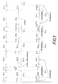
- Fig. 1 shows an example of a diagram to illustrate the Invention, being on a drum - according to the top line - Pieces of hose of the following lengths are wound up in succession: 17 m, 25 m, 11 m, 55 m, 32 m, 38 m, 15 m, 58 m, 17 m, ...
- the length of a federal government should be 50, for example m and the minimum length of a piece of hose is, for example, 5 m.
- the result along the middle line according to FIG. 1 is normal conventional winding method clarified, that is, the 17 m and the 25 m and of the 11 m piece are wound 8 m on a spool, so that 3 m of the 11 m hose piece remains as waste because this 3 m piece does not meet the minimum length requirement.
- the tube piece is then cut off 50 m. Meet the remaining 5 m the minimum length requirement.
- the 32 m hose section with 13 m of the subsequent hose section again to a 50 m bundle length combined.
- the remaining 25 m are with the 15 m hose piece and with combined a 10 m hose section of the 58 m long hose.
- 48 m remain as a short length.
- the bottom line in FIG. 1 illustrates the result of the winding method according to the invention, that is, the result when using the Plant according to the invention.
- the 17 m long piece of hose is as follows handled. 12 m of this piece of hose are fed to the winding station I. The remaining 5 m as well as the 25 m piece and the 11 m piece are combined with 9 m of the 55 m long hose section of the winding point II fed to the Winding point II to realize a bundle with 50 m hose length. 38 m of 55 m long piece of hose are then fed back to the winding station I to the winding station I to realize a bundle with a hose length of 50 m.
- the remaining 8 m of the 55 m long piece of hose are connected to the 32 m long Hose piece then again together with 10 m of the 38 m long Hose piece of the winding point II fed to a bundle with 50 m To produce hose length.
- the remaining 28 m of the 38 m long The hose section and the 15 m long hose section become 7 m of the 58 m long piece of hose at the winding point I to a 50 m long bundle combined.
- the subsequent 10 m are fed to the winding station II.
- the remaining 8 m of the 17 m long piece of hose will be then fed back to the winding station II etc. short lengths or the minimum length Waste that falls below is thus advantageously according to the invention avoided.
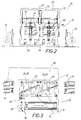
- Fig. 2 shows a front view of an embodiment of the system 10 for automatically optimized winding of hose pieces, in particular of steel or fabric armored hose pieces for the high or Maximum pressure range on a coil device 12 for the production of defined Hose bundles, that is, for the production of hose bundles of a defined Total length, with the individual tube pieces being a defined minimum length have.
- the coil device 12 has two coils arranged next to one another 14, which form the winding stations, as described above in connection with FIG. 1 Winding point I and are referred to as winding point II.
- the two coils 14 are one Hose guide unit 16 assigned.
- the hose guide unit 16 serves for feeding the respective hose section of the respective hose piece to one or the other coil 14, that is alternately to the winding point I and to the winding point II.
- the coils 14, the hose guide unit 16 and one Cutting device 18 for the defined severing of the respective Hose piece are provided on a system frame 20.
- the system 10 has a computer, not shown, in which a protocol the pre-checked wound on a drum, also not shown Hose pieces is saved.
- the calculator is with a not shown Control device of the system 10 connected.
- Each coil 14 has one vertically oriented winding core 22 and a lower coil limit 24 and an upper coil limit 26.
- the respective lower coil limit 24 is fixed, that means not adjustable in height.
- the respective top Coil limit 26 is through the control means mentioned above Controlled adjustable in height in order to maintain a constant inner diameter and constant outside diameter of the respective coil to be wound axial distance between the lower and upper coil limit 24 and 26 to be adjusted according to the respective total hose length. This Adjustability is illustrated in FIG. 2 by the double arrow 28.
- the winding core 22 of the respective coil 14 has a first drive device 30 connected.
- the axially adjustable upper coil limit 26 of the respective Coil 14 is connected to an associated second drive device 32.
- the two second drive devices 32 of the two coils 14 are - like that first drive device 30 - with the control device mentioned connected together.
- band storage devices 34 for Binding material provided with which the respective bundle on the corresponding Coil 14 is tied.
- Each coil 14 are also binding devices 36 assigned, also with the control device, not shown are interconnected.
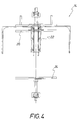
- FIG. 3 illustrates sections of one associated with the coil device 12 Removal device 38 to which the hose bundle has a defined bundle length and Defined minimum length of hose from the coils 14, that is, from the Hand over winding stations I and II and be transported away from the system 10.
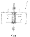
- Fig. 4 shows one of the coils 14 and the corresponding winding point in the open State
- Fig. 5 shows the corresponding coil or winding point in closed state.
- the same details are in Figs. 4 and 5 with the same reference numerals as in Figs. 2 and 3, so that it superfluous, in connection with FIGS. 4 and 5 all these details again to describe in detail. From the figures it can be seen that the respective Winding point lies in the horizontal.
- the respective winding core 22 is the one first drive device 30 having pull-out device in the vertical direction can be pulled out of the respective hose collar.
- the width setting of the respective coil that is the axial distance between the fixed lower Coil limit 24 and the adjustable upper coil limit 26 takes place expediently electrically via a second drive device forming servo drive automatically according to that with the computer performed calculation.
- the system 10 is regulated so that Hose remnants that are shorter than those specified by the customer Minimum hose lengths are to be avoided.
- the winding core 22 of the respective coil 14 is designed such that it can be Diameter when lowering the winding core 22 to the lower Coil limit 24 enlarged and thus when pulling out Core from the wound bundle of defined total tube length again reduced so that the winding core 22 easily from said bundle pulled out and the federal government to be transferred to the removal device 38 can.
- the lower and upper coil limit 24 and 26 of the respective The winding station is constructed and is mechanically separated from each other electrically synchronized.
Landscapes
- Storage Of Web-Like Or Filamentary Materials (AREA)
Abstract

Description
- Fig. 1
- in einer Diagrammdarstellung ein Beispiel von auf eine Trommel aufgewickelten Schlauchstücken bestimmter Längen und eine Gegenüberstellung des Ergebnisses einer herkömmlichen Wickelmethode im Vergleich mit der erfindungsgemäßen modifizierten Wickelmethode mit den beispielhaften Vorgaben: Bundlänge = 50 m, Mindestlänge = 5 m,
- Fig. 2
- eine Seitenansicht einer bevorzugten Ausbildung der erfindungsgemäßen Anlage,
- Fig. 3
- eine Ansicht der Anlage gemäß Fig. 2 in Blickrichtung von oben,
- Fig. 4
- eine Seitenansicht einer Wickelstelle im geöffneten Zustand und
- Fig. 5
- die Wickelstelle gemäß Fig. 4 im geschlossenen Zustand.
Claims (7)
- Anlage zum automatischen optimierten Aufwickeln von Schlauchstücken, insbesondere von armierten Schlauchstücken für den Hoch- oder Höchstdruckbereich, auf Spulen (14) einer Spuleneinrichtung (12) zur Herstellung von Schlauchbunden definierter Schlauchgesamtlänge,
dadurch gekennzeichnet, daß die Spuleneinrichtung (12) mindestens zwei nebeneinander angeordnete Spulen (14) aufweist, welchen eine Schlauchführungseinheit (16) zugeordnet ist, daß die Anlage (10) einen Rechner aufweist, in dem ein Protokoll über die Länge von auf eine Trommel aufgewickelten, vorkontrollierten Schlauchstücke gespeichert ist und daß der Rechner mit einer Steuerungseinrichtung der Anlage (10) verbunden ist, wobei jede Spule (14), die einen vertikal orientierten Wickelkern (22) mit einer oberen und einer unteren Spulenbegrenzung (24 und 26) aufweist, mit einer ersten Antriebseinrichtung (30) zum axialen Verstellen des Wickelkernes (22)und eine der Spulenbegrenzungen (26) mit einer zweiten Antriebseinrichtung (32) zur definierten Einstellung des axialen Abstandes zwischen den beiden Spulenbegrenzungen (24, 26) verbunden ist, wobei die Steuerungseinrichtung mit der ersten und der zweiten Antriebseinrichtung (30 und 32), mit der Schlauchführungseinheit (16) und mit einer Schneideinrichtung (18) zusammengeschaltet ist. - Anlage nach Anspruch 1,
dadurch gekennzeichnet, daß der jeweiligen Spule (14) ein Bindegerät (36) zum Abbinden des an der entsprechenden Spule (14) gewickelten Schlauchbundes zugeordnet ist, das mit der Steuerungseinrichtung zusammengeschaltet ist. - Anlage nach Anspruch 1,
dadurch gekennzeichnet, daß der Spuleneinrichtung (12) eine Abtransporteinrichtung (38) für die Schlauchbunde definierter Schlauchgesamtlänge und definierter Schlauchstück-Mindestlänge zugeordnet ist. - Anlage nach Anspruch 1,
dadurch gekennzeichnet, daß die untere Spulenbegrenzung (24) der jeweiligen Spule (14) ortsfest vorgesehen ist und daß die zugehörige obere Spulenbegrenzung (26) mit der zweiten Antriebseinrichtung (32) verbunden ist. - Anlage nach Anspruch 1,
dadurch gekennzeichnet, daß der Rechner mit einem Barcodeleser verbunden ist, der zum Lesen eines an der jeweiligen Trommel angeordneten Barcodes vorgesehen ist. - Anlage nach Anspruch 1,
dadurch gekennzeichnet, daß der Wickelkern (22) in seinem Durchmesser veränderbar ist. - Anlage nach Anspruch 1,
dadurch gekennzeichnet, daß der jeweiligen Spule (14) eine Anlageeinrichtung zugeordnet ist, die zum automatischen Anlegen des jeweiligen Schlauchstückes an den zugehörigen Wickelkern (22) vorgesehen ist.
Applications Claiming Priority (2)
| Application Number | Priority Date | Filing Date | Title |
|---|---|---|---|
| DE10063051 | 2000-12-18 | ||
| DE2000163051 DE10063051C2 (de) | 2000-12-18 | 2000-12-18 | Anlage zum automatischen optimierten Aufwickeln von Schlauchstücken |
Publications (2)
| Publication Number | Publication Date |
|---|---|
| EP1215153A2 true EP1215153A2 (de) | 2002-06-19 |
| EP1215153A3 EP1215153A3 (de) | 2003-04-02 |
Family
ID=7667635
Family Applications (1)
| Application Number | Title | Priority Date | Filing Date |
|---|---|---|---|
| EP01129696A Withdrawn EP1215153A3 (de) | 2000-12-18 | 2001-12-13 | Anlage zum automatischen optimierten Aufwickeln von Schlauchstücken |
Country Status (2)
| Country | Link |
|---|---|
| EP (1) | EP1215153A3 (de) |
| DE (1) | DE10063051C2 (de) |
Cited By (16)
| Publication number | Priority date | Publication date | Assignee | Title |
|---|---|---|---|---|
| CN103213870A (zh) * | 2013-02-06 | 2013-07-24 | 广州中国科学院先进技术研究所 | 自动盘软管机 |
| CN106516879A (zh) * | 2016-12-14 | 2017-03-22 | 大连德昌线缆有限公司 | 包装绕线机 |
| CN109230821A (zh) * | 2018-09-28 | 2019-01-18 | 德清县金丝源纺织品有限公司 | 灵活性好的纱线整理机构 |
| CN109297378A (zh) * | 2018-09-28 | 2019-02-01 | 德清县金丝源纺织品有限公司 | 具有计数功能的摇丝设备 |
| CN109368388A (zh) * | 2018-09-28 | 2019-02-22 | 德清县金丝源纺织品有限公司 | 移动方便的摇丝装置 |
| CN109368387A (zh) * | 2018-09-28 | 2019-02-22 | 德清县金丝源纺织品有限公司 | 为打样机提供纱线的纱线整理设备 |
| CN109368390A (zh) * | 2018-09-28 | 2019-02-22 | 德清县金丝源纺织品有限公司 | 能够计数的纱线扛丝机 |
| CN109368385A (zh) * | 2018-09-28 | 2019-02-22 | 德清县金丝源纺织品有限公司 | 纱线高效梳理装置 |
| CN109368382A (zh) * | 2018-09-28 | 2019-02-22 | 德清县金丝源纺织品有限公司 | 纱线整理设备 |
| CN109436938A (zh) * | 2018-11-28 | 2019-03-08 | 潍坊凯德塑料机械有限公司 | 塑料管材在线自动换卷切割捆扎卸卷装置 |
| CN110255285A (zh) * | 2019-05-23 | 2019-09-20 | 广东可得智能科技有限公司 | 一种色带生产用收卷装置 |
| CN110713071A (zh) * | 2018-08-08 | 2020-01-21 | 杭州富通通信技术股份有限公司 | 用于预制尾纤制造工艺的分切设备 |
| CN111039098A (zh) * | 2019-12-24 | 2020-04-21 | 邹忠菁 | 一种消防软管的存储回收装置 |
| CN112591550A (zh) * | 2020-12-23 | 2021-04-02 | 王玉彬 | 一种钢丝生产线上料加工装置 |
| CN113120679A (zh) * | 2021-03-03 | 2021-07-16 | 潘少华 | 一种纺织绕线器及其操作方法 |
| CN115285798A (zh) * | 2022-09-16 | 2022-11-04 | 常州市新创智能科技有限公司 | 一种双工位纤维收卷机构及其气动控制方法 |
Family Cites Families (7)
| Publication number | Priority date | Publication date | Assignee | Title |
|---|---|---|---|---|
| ES400106A1 (es) * | 1971-02-27 | 1975-06-16 | Alberto | Perfeccionamientos en una maquina automatica para formar rollos de tejido en pieza. |
| DE3209021A1 (de) * | 1982-03-12 | 1983-09-15 | Reinking Maschinenbau GmbH, 4993 Rahden | Drahtspuler |
| DE8711560U1 (de) * | 1987-08-26 | 1987-12-10 | Deißenberger, Hans, 7240 Horb | Vorrichtung zum Ablängen, Wickeln und Abbinden von Wickelgut |
| DE4006527A1 (de) * | 1990-02-22 | 1991-08-29 | Lapp Kg U I | Haspel zum aufwickeln von kabeln, schlaeuchen und dergleichen |
| DE4142262A1 (de) * | 1991-07-26 | 1993-01-28 | Klaus Dipl Ing Goerke | Verfahren zum aufwickeln von rohren |
| WO1996009431A1 (de) * | 1994-09-21 | 1996-03-28 | Wolf Merz Ag | Verfahren zur verarbeitung von warenbahnen |
| ES2217526T3 (es) * | 1998-10-07 | 2004-11-01 | Maillefer S.A. | Dispositivo para la confeccion de rollos de un lemento oblongo. |
-
2000
- 2000-12-18 DE DE2000163051 patent/DE10063051C2/de not_active Expired - Fee Related
-
2001
- 2001-12-13 EP EP01129696A patent/EP1215153A3/de not_active Withdrawn
Cited By (24)
| Publication number | Priority date | Publication date | Assignee | Title |
|---|---|---|---|---|
| CN103213870A (zh) * | 2013-02-06 | 2013-07-24 | 广州中国科学院先进技术研究所 | 自动盘软管机 |
| CN103771188A (zh) * | 2013-02-06 | 2014-05-07 | 广州中国科学院先进技术研究所 | 一种自动盘软管机 |
| CN103771187A (zh) * | 2013-02-06 | 2014-05-07 | 广州中国科学院先进技术研究所 | 自动盘软管系统 |
| CN103213870B (zh) * | 2013-02-06 | 2016-06-15 | 广州中国科学院先进技术研究所 | 自动盘软管机 |
| CN103771188B (zh) * | 2013-02-06 | 2016-06-15 | 广州中国科学院先进技术研究所 | 一种自动盘软管机 |
| CN103771187B (zh) * | 2013-02-06 | 2016-06-29 | 广州中国科学院先进技术研究所 | 自动盘软管系统 |
| CN106516879A (zh) * | 2016-12-14 | 2017-03-22 | 大连德昌线缆有限公司 | 包装绕线机 |
| CN110713071B (zh) * | 2018-08-08 | 2021-09-21 | 杭州富通通信技术股份有限公司 | 用于预制尾纤制造工艺的分切设备 |
| CN110713071A (zh) * | 2018-08-08 | 2020-01-21 | 杭州富通通信技术股份有限公司 | 用于预制尾纤制造工艺的分切设备 |
| CN109368385A (zh) * | 2018-09-28 | 2019-02-22 | 德清县金丝源纺织品有限公司 | 纱线高效梳理装置 |
| CN109297378A (zh) * | 2018-09-28 | 2019-02-01 | 德清县金丝源纺织品有限公司 | 具有计数功能的摇丝设备 |
| CN109368390A (zh) * | 2018-09-28 | 2019-02-22 | 德清县金丝源纺织品有限公司 | 能够计数的纱线扛丝机 |
| CN109368388A (zh) * | 2018-09-28 | 2019-02-22 | 德清县金丝源纺织品有限公司 | 移动方便的摇丝装置 |
| CN109368382A (zh) * | 2018-09-28 | 2019-02-22 | 德清县金丝源纺织品有限公司 | 纱线整理设备 |
| CN109230821A (zh) * | 2018-09-28 | 2019-01-18 | 德清县金丝源纺织品有限公司 | 灵活性好的纱线整理机构 |
| CN109368387A (zh) * | 2018-09-28 | 2019-02-22 | 德清县金丝源纺织品有限公司 | 为打样机提供纱线的纱线整理设备 |
| CN109436938B (zh) * | 2018-11-28 | 2021-02-02 | 潍坊凯德塑料机械有限公司 | 塑料管材在线自动换卷切割捆扎卸卷装置 |
| CN109436938A (zh) * | 2018-11-28 | 2019-03-08 | 潍坊凯德塑料机械有限公司 | 塑料管材在线自动换卷切割捆扎卸卷装置 |
| CN110255285A (zh) * | 2019-05-23 | 2019-09-20 | 广东可得智能科技有限公司 | 一种色带生产用收卷装置 |
| CN111039098A (zh) * | 2019-12-24 | 2020-04-21 | 邹忠菁 | 一种消防软管的存储回收装置 |
| CN112591550A (zh) * | 2020-12-23 | 2021-04-02 | 王玉彬 | 一种钢丝生产线上料加工装置 |
| CN113120679A (zh) * | 2021-03-03 | 2021-07-16 | 潘少华 | 一种纺织绕线器及其操作方法 |
| CN115285798A (zh) * | 2022-09-16 | 2022-11-04 | 常州市新创智能科技有限公司 | 一种双工位纤维收卷机构及其气动控制方法 |
| CN115285798B (zh) * | 2022-09-16 | 2022-12-02 | 常州市新创智能科技有限公司 | 一种双工位纤维收卷机构及其气动控制方法 |
Also Published As
| Publication number | Publication date |
|---|---|
| EP1215153A3 (de) | 2003-04-02 |
| DE10063051C2 (de) | 2002-12-19 |
| DE10063051A1 (de) | 2002-06-27 |
Similar Documents
| Publication | Publication Date | Title |
|---|---|---|
| DE10063051C2 (de) | Anlage zum automatischen optimierten Aufwickeln von Schlauchstücken | |
| DE102009026849B3 (de) | Spulmaschine mit einer Wechseleinrichtung und Verfahren zum Betrieb derselben | |
| DE10035894B4 (de) | Wickeleinrichtung für Bandmaterial | |
| DE2709248C2 (de) | Verfahren und Vorrichtung zum Umschnüren von Ballen | |
| DE1955246C3 (de) | Vorrichtung zum kontinuierlichen Aufwickeln drahtförmigen Gutes | |
| CH643409A5 (de) | Vorrichtung zum wickeln von spulen fuer statoren elektrischer maschinen. | |
| DE2833955C2 (de) | Einzelspuler zum Aufwickeln von Stranggut, insbesondere von Draht | |
| EP4091808B1 (de) | Verfahren zum verändern der umreifung sowie ballenpresse zur anwendung dieses verfahrens | |
| DE102011000590B3 (de) | Spulmaschine | |
| DD208337A5 (de) | Verfahren und vorrichtung zum kontinuierlichen spulenwechsel an ein- oder mehrgaengigen, kontinuierlich arbeitenden wickelstationen fuer strangfoermiges gut | |
| DE69332363T2 (de) | Verfahren und Vorrichtung zur Herstellung von Amorphenstahlbandespaketten zur Herstellung von Transformatorkern | |
| EP0093301B1 (de) | Vorrichtung zum Austauschen eines mit Wickelgut bewickelten Wickelkerns | |
| EP1660400A1 (de) | Verfahren und vorrichtung zum positionieren mehrerer h lsen in einer spulmaschine | |
| DE3736191A1 (de) | Vorrichtung und verfahren zum bearbeiten eines fadens einer fadenspule | |
| DE4119290A1 (de) | Vorrichtung zum spulenwechsel in einer bandmaterial verarbeitenden maschine | |
| DE2640849A1 (de) | Verfahren und vorrichtung zum entnehmen von materialkoerpern aus einer spulmaschine | |
| EP0130473B1 (de) | Abwickelvorrichtung für Adern von Spulen in der Kabelindustrie | |
| WO2015185288A1 (de) | Vorrichtung und verfahren zum magazinlosen bewickeln von ringkernen | |
| DE3334761A1 (de) | Verfahren und vorrichtung zum einziehen von spulen und von zwischenisolatoren in blechpakete | |
| DE3446692C2 (de) | ||
| DE102015008378A1 (de) | Vorrichtung zum Aufnehmen und Abtransportieren von gewickelten Spulen | |
| DE19638250C1 (de) | Drahtführungsvorrichtung für eine Spulenwickelmaschine | |
| DE3614321C2 (de) | ||
| EP0304606A2 (de) | Anlage zum Ablängen, Wickeln und Abbinden von Wickelgut | |
| DE2727906A1 (de) | Verfahren und vorrichtung zum aufspulen eines vorderen drahtendes auf eine spule |
Legal Events
| Date | Code | Title | Description |
|---|---|---|---|
| PUAI | Public reference made under article 153(3) epc to a published international application that has entered the european phase |
Free format text: ORIGINAL CODE: 0009012 |
|
| AK | Designated contracting states |
Kind code of ref document: A2 Designated state(s): AT BE CH CY DE DK ES FI FR GB GR IE IT LI LU MC NL PT SE TR |
|
| AX | Request for extension of the european patent |
Free format text: AL;LT;LV;MK;RO;SI |
|
| PUAL | Search report despatched |
Free format text: ORIGINAL CODE: 0009013 |
|
| AK | Designated contracting states |
Kind code of ref document: A3 Designated state(s): AT BE CH CY DE DK ES FI FR GB GR IE IT LI LU MC NL PT SE TR Designated state(s): AT BE CH CY DE DK ES FI FR GB GR IE IT LI LU MC NL PT SE TR |
|
| AX | Request for extension of the european patent |
Extension state: AL LT LV MK RO SI |
|
| 17P | Request for examination filed |
Effective date: 20030402 |
|
| AKX | Designation fees paid |
Designated state(s): AT BE CH CY DE DK ES FI FR GB GR IE IT LI LU MC NL PT SE TR |
|
| GRAP | Despatch of communication of intention to grant a patent |
Free format text: ORIGINAL CODE: EPIDOSNIGR1 |
|
| STAA | Information on the status of an ep patent application or granted ep patent |
Free format text: STATUS: THE APPLICATION IS DEEMED TO BE WITHDRAWN |
|
| 18D | Application deemed to be withdrawn |
Effective date: 20041012 |