EP1215063B1 - Store à enrouler de fenêtre avec montage simplifié - Google Patents
Store à enrouler de fenêtre avec montage simplifié Download PDFInfo
- Publication number
- EP1215063B1 EP1215063B1 EP01129145A EP01129145A EP1215063B1 EP 1215063 B1 EP1215063 B1 EP 1215063B1 EP 01129145 A EP01129145 A EP 01129145A EP 01129145 A EP01129145 A EP 01129145A EP 1215063 B1 EP1215063 B1 EP 1215063B1
- Authority
- EP
- European Patent Office
- Prior art keywords
- roller blind
- window roller
- blind according
- guide
- guide rail
- Prior art date
- Legal status (The legal status is an assumption and is not a legal conclusion. Google has not performed a legal analysis and makes no representation as to the accuracy of the status listed.)
- Expired - Lifetime
Links
Images


Classifications
-
- B—PERFORMING OPERATIONS; TRANSPORTING
- B60—VEHICLES IN GENERAL
- B60J—WINDOWS, WINDSCREENS, NON-FIXED ROOFS, DOORS, OR SIMILAR DEVICES FOR VEHICLES; REMOVABLE EXTERNAL PROTECTIVE COVERINGS SPECIALLY ADAPTED FOR VEHICLES
- B60J1/00—Windows; Windscreens; Accessories therefor
- B60J1/20—Accessories, e.g. wind deflectors, blinds
- B60J1/2011—Blinds; curtains or screens reducing heat or light intensity
- B60J1/2013—Roller blinds
- B60J1/2066—Arrangement of blinds in vehicles
- B60J1/2075—Arrangement of blinds in vehicles specially adapted for fixed windows
- B60J1/208—Arrangement of blinds in vehicles specially adapted for fixed windows for rear windows
-
- B—PERFORMING OPERATIONS; TRANSPORTING
- B60—VEHICLES IN GENERAL
- B60J—WINDOWS, WINDSCREENS, NON-FIXED ROOFS, DOORS, OR SIMILAR DEVICES FOR VEHICLES; REMOVABLE EXTERNAL PROTECTIVE COVERINGS SPECIALLY ADAPTED FOR VEHICLES
- B60J1/00—Windows; Windscreens; Accessories therefor
- B60J1/20—Accessories, e.g. wind deflectors, blinds
- B60J1/2011—Blinds; curtains or screens reducing heat or light intensity
- B60J1/2013—Roller blinds
- B60J1/2019—Roller blinds powered, e.g. by electric, hydraulic or pneumatic actuators
- B60J1/2027—Roller blinds powered, e.g. by electric, hydraulic or pneumatic actuators with a buckle-proof guided flexible actuating element acting on the draw bar for pushing or push-pulling, e.g. a Bowden cable
-
- B—PERFORMING OPERATIONS; TRANSPORTING
- B60—VEHICLES IN GENERAL
- B60J—WINDOWS, WINDSCREENS, NON-FIXED ROOFS, DOORS, OR SIMILAR DEVICES FOR VEHICLES; REMOVABLE EXTERNAL PROTECTIVE COVERINGS SPECIALLY ADAPTED FOR VEHICLES
- B60J1/00—Windows; Windscreens; Accessories therefor
- B60J1/20—Accessories, e.g. wind deflectors, blinds
- B60J1/2011—Blinds; curtains or screens reducing heat or light intensity
- B60J1/2013—Roller blinds
- B60J1/2036—Roller blinds characterised by structural elements
- B60J1/2052—Guides
-
- B—PERFORMING OPERATIONS; TRANSPORTING
- B60—VEHICLES IN GENERAL
- B60J—WINDOWS, WINDSCREENS, NON-FIXED ROOFS, DOORS, OR SIMILAR DEVICES FOR VEHICLES; REMOVABLE EXTERNAL PROTECTIVE COVERINGS SPECIALLY ADAPTED FOR VEHICLES
- B60J1/00—Windows; Windscreens; Accessories therefor
- B60J1/20—Accessories, e.g. wind deflectors, blinds
- B60J1/2011—Blinds; curtains or screens reducing heat or light intensity
- B60J1/2013—Roller blinds
- B60J1/2063—Mounting arrangements for roller blind or its storage box, e.g. integration into beltline or window frame
Definitions
- Modern body shapes are characterized by relatively large windows.
- the large windows lead due to the strong sunlight to a considerable heating of the vehicle interior, and in vehicles with air conditioning means the strong heating a not inconsiderable energy consumption to counteract the vehicle heating.
- the motor vehicles are therefore increasingly equipped with window blinds.
- the guide rails for such window blinds are quite filigree structures. They are made of light metal and are therefore very sensitive to bending. Even small forces are sufficient to destroy them, as long as they are not attached to a stable supporting part.
- the guide rails must be mounted in the correct position to the winding shaft, or the winding shaft in the correct position to the guide rails. Only after attaching the winding shaft and the guide rails, the tension rod can be threaded into the guide rails.
- the guide rails are designed in two parts. One part is firmly connected to the bearing means, while the other part of each guide rail can be joined by plugging with the first part. Another possibility is to connect the two parts of each guide rail with each other via a hinge.
- the hinge may be a hinged hinge pin hinge or a film hinge or a predetermined bending point.
- connecting means and / or the bearing means may be provided with appropriate measures to secure these parts in the vehicle.
- the assembly can be further simplified if the assembly additionally has the drive motor and the guide tubes for the drive links. Finally, almost complete prefabrication of the assembly is possible if the assembly additionally carries the guide rails or at least a portion of them. As a result, a complete pre-assembly by the manufacturer of the window blinds is possible.
- a hinge allows a very compact unit to be delivered to the belt becomes. By removing or folding the relevant parts of the guide rails, a structural unit is obtained from which no parts protrude expansively.
- the hinge Since the hinge is actuated practically only twice, namely in the sense of folding after the manufacturer-side assembly and the sense of erection during assembly in the vehicle, the hinge can also be formed by predetermined bending points, which can also be regarded as a film hinge. So it is possible even when using guide rails made of extruded aluminum profile, the guide rails from the back several times cut. Due to the cuts remain on the side of the slot next to this two narrow webs of material that can be bent back and forth a few times without breaking. The use of multiple cuts reduces the amount of deflection that occurs on a pair of webs when folding the respective guide rail section.
- the guide rails are expediently designed to be material or form-fitting connected to the vehicle body.
- they can either be provided with adhesive surfaces or with flange-shaped webs, which are suitable for screwing or gluing.
- a connection via rivets for example blind rivets.
- the flange can also be glued between the disc and the body.
- the drive of the roller blind is done appropriately via drive links, which are preferably coupled positively to an electric motor.
- the drive members are linear elements which are provided on the outside with a toothing.
- the toothing is formed by a circumferential helical rib.
- the leadership of the drive links to the guide rails is done in pipes to avoid buckling in push members.
- the arrangement is similar to a Bowden cable.
- the guide tubes can have the same cross-sectional profile as the guide rails and they can even merge into one another in one piece.
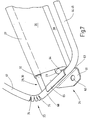
- Fig. 1 shows a schematic representation of the rear view of a car 1 with a roof 2, a trunk 3 and two C-pillars 4 and 5. Between the two C-pillars 4 and 5 is a rear window opening 6, the upward of a Roof trailing edge 7 and is bounded below by a lower edge of the window 8. In the rear window opening 6 sits in a known manner, for example glued by means of adhesive, a rear window. 9
- a hat shelf 11 which extends horizontally between the lower window edge 8 and a not recognizable in the figure rear seat backrest.
- a straight outlet slot 12 runs in the rear shelf 9 .
- the outlet slot 12 belongs to a rear window roller blind 13, the basic structure of which is illustrated in FIG. 2 in a highly schematic manner in a plan view.
- the rear window roller blind 12 has two guide rails 13, which are fastened to the two C-pillars 4 and 5 next to the lateral edges of the rear window opening 6. Because of the cutaway schematic diagram, only one guide rail 13 can be seen in FIG. 2, which is fastened, for example, to the C pillar 5.
- the type of attachment according to the invention is explained in detail below.
- the guide rail 13 has the cross-sectional profile shown in Figure 3. It is in cross-section substantially square with rounded corners and is bounded by a front side 14, two side walls 15 and 16 and a rear side 17. From the back 17 is a strip-like mounting flange 18 is made, with the help of the guide rail 13 is to be attached to corresponding body parts.
- the flange 18 define two mutually parallel surfaces 19 and 20, whose generatrix is a straight line which is perpendicular to the longitudinal axis of the guide rail 13.
- a circular in cross-section guide groove 21 is included, which opens via a slot 22 to the front side 14.
- the guide rail 13 consists for example of an aluminum extruded profile.
- the slot 22 is narrower than the diameter of the circular portion of the guide groove 21, creates a hintergriffige groove which is adapted to protect a linear thrust member against buckling and prevent the thrust member of a corresponding diameter from leaking through the slot 22 to the outside.
- the guide rails 13 are with respect to several axes bent so that they follow the contour of the edge of the window without being visible in the window itself.
- the guide rails 13 are arranged so that the grooves 21 open toward each other.
- the guide rails 13 run downwards, as Figure 2 reveals, through the slot 11 to below the parcel shelf.
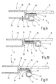
- a winding shaft 23 is rotatably mounted below the parcel shelf 9, as shown schematically in FIG. 2, a winding shaft 23 is rotatably mounted. Bearing blocks for supporting the winding shaft 23 are shown in Fig. 5 at 24.
- the winding shaft 23 is tubular and houses a spring motor 25, which is shown schematically in Fig. 4.
- the spring motor 25 consists of a coil spring which is fixed with one end inside the winding shaft 23 and the other end is anchored to one of the bearing blocks 24 for supporting the winding shaft 23.
- a roller blind 26 On the winding shaft 23, a roller blind 26 is fixed with an edge, the blank is a trapezoidal approximation of the contour of the rear window 6.
- the remote from the winding shaft 23 edge is formed into a tubular loop 26 in which a pull rod 27 is seated.
- To the pull rod 28 essentially includes a concealed by the loop 27 center piece and two opposite the center piece telescopically movable end pieces 29 and 30th
- the middle piece is an oval tube with a constant cross section, seen over the length.
- the length of the tube corresponds to the length of the tubular loop 27 and thus the corresponding edge of the roller blind 26th
- the end pieces 29 and 30 have an L-shaped configuration and is composed of an arm 32 and a guide piece 33 together.
- the arm 32 has such a cross-section that it is largely longitudinally displaceable in the interior of said tube. Its outboard end merges integrally into the guide piece 33 at 34, which is adapted in cross-section to the circular part of the guide groove 21, while the width of the arm 32 corresponds to the width of the slot 22.
- the two end pieces 29 and 30 are made equal in terms of the arm 32 and the guide piece 33.
- a drive device 35 is provided, which is shown in highly schematic form in FIG. To simplify the illustration and to explain the understanding of the invention, the two lateral guide rails 13 are shown cut in Figure 4. The two guide grooves 21 open towards each other.
- To the drive means 35 includes a geared motor 36, which is composed of a permanently excited DC motor 37 and a transmission housing 38.
- a geared motor 36 which is composed of a permanently excited DC motor 37 and a transmission housing 38.
- two guide channels 39 and 41 are parallel to each other, between which on an output shaft 42, an output gear 43 is provided.
- the output gear 43 can via the thus rotatably connected output shaft 42 either in both directions in motion be set.
- a guide tube 44 goes to the lower end of the guide groove 21 in the left guide rail 13.
- the guide channel 41 is connected at the right end via a guide tube 45 to the lower end of the guide groove 21 in the right guide rail 13.
- Each of the unused part of the thrust members 46, 47 is pushed back into storage tubes, which emanate from the other end of the guide channels 39, 41, respectively, through the guide channel 39 and through the guide channel 41 respectively a flexurally elastic, linear thrust member 46 and 47 ,
- the two push members 46 and 47 have the same structure. They each consist of an elastically flexible core 48, which carries on its outside one or more ribs 49, which form a single or multi-start thread there.
- the ribs 49 project radially and helically over the cylindrical core 48 from one end of the pusher to the other end.
- the output gear 43 carries a toothing, which can engage between the grooves formed by the ribs 49. In this way, the output gear 43 is positively coupled to the thrust members 46 and 47.
- the two push members 46 and 47 are spaced with their two ends of the respective guide members 33.
- roller blind 26 reduces the passage of light without completely suppressing it.
- the roller blind 26 for example, from an open warp knit or a perforated and black colored plastic film.
- the geared motor 36 is set in motion with such a direction of rotation that it moves the push member 47 to the right through the guide groove 21. Since the two push members 46 and 47 mesh on diametrically opposite sides with the output gear 43, the thrust member 46 is simultaneously advanced to the left by the guide groove 21 of the left guide rail 13 by the same amount. After a short distance of the feed path, the free ends of the two thrust members 46 and 47 engage with the lower ends of the guide members 33 of the two guide pieces 29, 30 and later slide the guide pieces 29, 30 toward the upper end of the two guide rails 13th
- the arms 32 dip telescopically at the same time the guide pieces 29, 30 in the contained in the respective loop 27 dimensionally stable tube of the tension rod a.
- the geared motor 36 is self-locking and locks the thrust members 46 and 47 in the respective achieved position.
- the switching off of the geared motor 36 takes place by means of limit switches or by the guide members 29 and 30 start at stops. There occurs a blocking current to be evaluated in an electronic unit, which leads to shutdown.
- roller blind 26 is now held clamped between the tension rod and the winding shaft 23.
- window blinds 12 As far as the basic principle of the window blinds 12 is explained so far, with reference to the following figures according to the invention Aspects described which make it possible to mount the window shade 12 in a simple manner on the assembly line for the motor vehicle 1. In this case, only sections of the window blind 12 are shown to explain the details of the invention, namely those sections that are essential for understanding the invention.
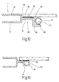
- Fig. 5 reveals an end of the winding shaft 23.
- the winding shaft 23 is rotatably supported as shown in FIG. 5 between two bearing blocks 24, of which only one can be seen because of the aborted representation.
- the bearing block 24 consists of a C-shaped sheet metal stamped part.
- the sheet metal stamping part forms a planar mounting leg 61 with a mounting hole 62 and a bearing leg 63 extending at right angles thereto, which contains a concealed bearing bore for a bearing journal 64 of the winding shaft 23.
- At the distal end of the mounting leg 62 of the bearing leg 63 another leg 65 is formed.
- the leg 65 serves to fasten the respective guide rail 13.
- the guide rail 13 is composed in the embodiment of FIG. 5, a first portion 66 and a second portion 67 together.
- the portion 66 is fixed in the angular region between the leg 65 and the bearing leg 63 of the bearing piece 61, for example by gluing or otherwise.
- the length of the portion 66 is selected so that when fully retracted window shade 12, the free edge, or the free end of the portion 66, seen in the direction of movement during extension, projects beyond the guide pieces 29 and 30 respectively.
- the two bearing blocks 24 are connected to each other by a frame tube 68.
- the frame tube 68 is welded, for example, at both ends with one of the bearing legs 63.
- the bearing legs 63 are facing each other, while the mounting legs 61 facing away from each other.
- the gear motor 35 is also attached on the frame tube 68.
- the guide tubes 44 and 54 are each integrally in the respective guide rail pieces 66, as this can be seen in Figure 5.
- the guide tubes 44 and 45 each consist of a piece of profile tube having an inner profile of FIG. 3, wherein optionally the lateral flange 18 is missing.
- the arrangement according to FIG. 5 forms a unit which can be preassembled by the manufacturer of the window roller blind.
- the unit consists of: the bearing blocks 24, which are rigidly and substantially immovably connected by the frame tube 68 together. Between the two bearing blocks 24, the winding shaft 23 is rotatably mounted, wherein additionally rotatably supported on one of the bearing flanges 63 of the spring motor 25.
- the tension rod is already threaded with its end pieces 29, 30 in the piece 66 in the guide rail 13. With the help of the spring motor 25, the arms 32 of the guide pieces 29, 30 are attracted against an edge of the bearing leg 63.
- the guide rail 13 which forms the guide tube 44 and 45, are preassembled, the push members 46 and 47, and it is preassembled on the frame tube 68 of the geared motor 36.
- this unit can be easily installed on the belt in the relevant motor vehicle without requiring the actual installation of the window blinds there.
- the second section 67 of the guide rails 13 is separated and is, for example, after assembly of the above-described unit comprising the winding shaft 23, mounted in the vehicle body and mated with the portion 66, the guide rail 13, for example via a connecting sleeve, not shown.
- the portion 67 was fixed by means of the flange 18 in the vehicle body. The way in which this happens will be explained in later drawings.
- the leg 65 is extended beyond the end of the portion 66 and forms a protruding tab 69.
- the tab 69 includes a hinge bore 71 in which a corresponding hinge pin 72 is seated, which is rigidly and firmly connected to the portion 67.
- the hinge axis is at right angles to the axis of rotation of the winding shaft 23rd
- the section 67 of the guide rail 13 is hinged, for example, in which the hinge pin 72 is rotatably riveted to the tab 69.
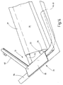
- the assembly of FIG. 6 is prepared in a similar manner as the assembly of FIG. It is now possible to deliver a structural unit to the assembly line in which the guide rails 13 are already contained in their entirety.
- the sections 67, the guide rails 13 are folded and are parallel to the already threaded tie rod.
- the portions 67 are pivoted out of position parallel to the winding shaft 23 into the position of use and secured in the vehicle.
- the connection between the section 67 and the section 66 of the guide rail can also be designed as a predetermined bending point, as shown in Fig. 7.
- the hinge consists of a predetermined bending point 73.
- the predetermined bending point 73 is achieved by the profile of the guide rail 13 is provided from the back as shown with several cuts 74, which ends shortly before the front end wall 14. In this way, 22 remain two narrow webs laterally next to the slot.
- the two guide rail sections 67, the two guide sheets 13 are folded inwards, wherein the guide rails bend at the predetermined bending points 73 with a corresponding radius.
- the guide rails 13 are bent back to the desired bending points 73 again in the desired position.
- the predetermined bending points 73 act as hinges that can be bent enough often without causing breakage. It is important to ensure a corresponding large depth of the incisions 74.
- the body usually contains an interior trim. This can be used to form a portion of the guide rail 13.
- Fig. 8 shows an embodiment in which the second portion 67 of the guide rail 13 is not a separate guide rail profile. Rather, this section 67 is included as a groove 75 in an interior trim piece 76 of the C-pillar 4 and 5 respectively.
- the groove 75 corresponds in its cross section exactly the groove 21 with the slot 22nd
- the mounting is done by attaching the interior trim pieces 76 in the body after attaching the aforementioned assembly. Not shown positioning ensure that the groove 75 is aligned with the groove 21 in the respective section 66.
- FIG. 9 shows a section through the vehicle body of the motor vehicle 1, namely a horizontal section, for example through the C Column 4.
- the C-pillar 4 is composed of two sheet-metal shaped parts, an outer sheet-metal shaped part 76 and an inner sheet-metal shaped part 77.
- the outer sheet metal part 76 forms at the rear window 6 a fold 78 which terminates in a sheet metal flange 79.
- the inner sheet metal part 77 is also provided with a fold 79 which terminates in a flange 81.
- the two flanges 79 and 81 are straight flanges, in the sense that their generatrix is a straight line which is perpendicular to the edge and lies in the plane of the rear window opening 6.
- the two flanges 79 and 81 are connected in a known manner by spot welding cohesively.
- the rear window 9 is optionally glued on the edge side with the interposition of a leveling compound and adhesive 82.
- the groove 21 is located in the fold 80. That part of the guide rail 13 which extends adjacent to the rear window opening 6 is fixed by means of the flange 18 on the vehicle interior facing surface of the inner sheet metal part 77 next to the fold 80.
- the attachment takes place for example by screws or rivets, as indicated schematically at 83. The screws or rivets pass through holes in the flange 18 and the sheet metal part 77 through.
- the essential advantage of the arrangement according to Fig. 9 is that the voluminous part of the guide rail 13, namely that part with the guide groove 21 in the inner fold 80 is included, so that it does not contribute to reinforcement of the body thickness including the inner lining in this area ,
- the guide rail 13 is in close proximity to the visible edge formed by the free edge of the flange 79 and 81st
- FIG. 9 is also suitable for such body parts such as vehicle doors, where no flange is present because the discs is guided in guides displaced.
- Fig. 10 shows a connection in which the flange 18 of the guide rail 13 is inserted between the flange 78 and the disc 9.
- the flange 18 is laterally offset as shown and opens tangentially in those cross-sectional area of the guide rail 13, in which the groove 21 is included.
- the flange 18 is glued by means of an adhesive 84 on the outside of the flange 79.
- the flange 18 in turn forms the supporting and holding surface for the disc 9, which is mounted on the flange 18 in the same manner as in Fig. 9 on the flange 79th
- the window inner edge formed directly from the side 14 of the guide rail 13.
- the flange 18 is not a straight bar, which is bounded by two mutually parallel surfaces, but the flange 18 is angled and integrally formed on the surface 15, for example.
- the groove 85 is sized to receive a bent leg 86 of the inner flange 81.
- the flange 81 is for this purpose bent at its free, pointing in the direction of the center of the window opening 6 edge to form a leg 78 spaced from the leg, can be plugged onto the guide rail 13 with the groove 85.
- Fig. 12 shows an arrangement in which the bend made in Fig. 11 has a greater spatial depth, so that the leg 86 from the inside of the rear window glass 9 has a distance that leaves a larger groove-shaped chamber 87 is formed.
- the dimensions of the groove-shaped chamber 87 are sufficient to accommodate the guide rail 13 there.
- the guide rail 13 is executed in this case without the flange 18 and instead has a straight side surface 88 with which it is glued on the leg 86.
- the guide rail 13 is located within the chamber 87 between the leg 86 and the inside of the rear window glass. 9
- the rear window glass 9 is fixed in the same manner as explained in connection with FIG. 9.
- the outer cross section of the guide rail 13 necessarily needs to be square. It can also be cylindrical.
- Fig. 13 shows an embodiment in which the portion 67 of the guide rail 13 is formed by the body itself.
- the flange 79 is provided at its free edge with a one-piece bar 89 which points away from the disc 9.
- the leg 86 also carries at its free end a bar 91 which is aligned with the bar 89 and points to this. This results in a groove 92 with slot 93, which corresponds in cross section to the groove 21 with the slot 22.
- Figures 9-13 make it readily apparent that the window shade 12 can be mounted even before the pane 9 is glued.
- the window shade 12 is placed on the window opening from the outside and the guide rails 13 are connected to the flanges 79 and / or 81 from the outside.
- the assembly can be further simplified if, as shown in FIG. 14, the flange 65 of the bearing block 24 at the same time also serves as a mounting flange by a corresponding piece is extended. It is glued in this case from the outside to the outside of the flange 79.
- a window roller blind comprises a preassembled unit, consisting at least of the winding shaft, the associated Bearing pieces and connecting the bearing pieces frame tube.
- a preassembled unit of the electric drive motor and guide tubes to guide thrust members for actuating the roller blind.
- the runway is connected to a tie rod, which is guided end in guide rail pieces, which are also part of the assembly.
- a flange for fixing a disc is provided.
- the flange also serves as a fixture for the guide rails, so that they approach as close to the disc opening without disturbing appear.
Claims (28)
- Store à enrouleur de fenêtre (12) pour régler l'entrée de la lumière dans l'habitacle d'un véhicule à travers la fenêtre, qui comporte :- au moins un arbre d'enroulement (23),- des moyens de palier (24) dans lesquels est monté tournant l'arbre d'enroulement (23),- des moyens de liaison (68) par lesquels les moyens de palier (24) sont reliés entre eux, les moyens (24) et/ou les moyens (68) étant conçus pour être montés sur le véhicule automobile (1),- au moins une bande de store (26) qui est fixée par un bord à l'arbre d'enroulement (23),- au moins une paire de rails de guidage (13) dont chacune s'étend en étant au moins un peu écartée latéralement le long de la bande de store (26) et présente au moins une rainure de guidage (21),- une tige de tension (28) qui est reliée à un bord (27) de la bande de store (26) éloigné de l'arbre d'enroulement (23) et qui est guidée par ses extrémités dans les rainures de guidage (21),- un dispositif d'entraînement (35) pour déplacer la tige de tension (28) le long des rails de guidage (13) et pour faire tourner l'arbre d'enroulement (23),étant précisé que chaque rail de guidage (13) est divisé en une première et en une seconde section (66, 67) dont la première (66) est reliée au moyen de palier (24) et présente une longueur telle que, par rapport à la longueur totale du rail de guidage (13), elle dépasse seulement un peu la tige de tension (28) quand le store à enrouleur de fenêtre (12) est en position rentrée.
- Store à enrouleur de fenêtre selon la revendication 1, caractérisé en ce que l'arbre d'enroulement (23) a la forme d'un tube et contient un moteur élastique (25) faisant partie du dispositif d'entraînement (35).
- Store à enrouleur de fenêtre selon la revendication 1, caractérisé en ce que le moyen de palier (24) présente une bride de montage (61, 65) pour fixation dans le véhicule automobile (1).
- Store à enrouleur de fenêtre selon la revendication 1, caractérisé en ce que le moyen de palier (24) est une pièce pliée en tôle.
- Store à enrouleur de fenêtre selon la revendication 1, caractérisé en ce que la bride de montage (61, 65) est conçue pour être fixée au véhicule automobile (1) avec verrouillage par combinaison de formes ou par la matière.
- Store à enrouleur de fenêtre selon la revendication 1, caractérisé en ce que la bande de store (25) présente une coupe qui est proche de la forme de la fenêtre.
- Store à enrouleur de fenêtre selon la revendication 1, caractérisé en ce que les rails de guidage (13) sont reliés au moins en partie aux moyens de palier (64) et aux moyens de liaison (68) pour donner une unité constructive préassemblée.
- Store à enrouleur de fenêtre selon la revendication 1, caractérisé en ce que le rail de guidage (13) présente un tracé qui correspond au bord associé de la fenêtre.
- Store à enrouleur de fenêtre selon la revendication 1, caractérisé en ce que le rail de guidage (13) est conçu de manière à pouvoir être relié au moins en partie au véhicule (1) avec verrouillage par combinaison de formes et/ou par la matière.
- Store à enrouleur de fenêtre selon la revendication 1, caractérisé en ce que le rail de guidage (13) présente au moins une surface continue (10, 20, 28) ayant pour génératrice une droite perpendiculaire à l'axe longitudinal du rail de guidage (13).
- Store à enrouleur de fenêtre selon la revendication 1, caractérisé en ce que le rail de guidage (13) présente au moins deux surfaces (19, 20) parallèles entre elles, dont les génératrices sont des droites perpendiculaire à l'axe longitudinal du rail de guidage (13).
- Store à enrouleur de fenêtre selon la revendication 1, caractérisé en ce que le rail de guidage (13), sur son côté éloigné de la fente de rainure (22), présente une bride de fixation (18) qui est conçue pour être reliée au véhicule (1) avec verrouillage par combinaison de formes et/ou par la matière.
- Store à enrouleur de fenêtre selon la revendication 1, caractérisé en ce que la seconde section (67) du rail de guidage est disposée ou réalisée dans une pièce de revêtement latéral (76) du véhicule automobile (1).
- Store à enrouleur de fenêtre selon la revendication 1, caractérisé en ce que les deux sections (66, 67) sont reliées entre elles par une charnière (71, 72, 73).
- Store à enrouleur de fenêtre selon la revendication 14, caractérisé en ce que l'axe de basculement de la charnière (71, 72, 73) est perpendiculaire à l'axe de rotation de l'arbre d'enroulement (23).
- Store à enrouleur de fenêtre selon la revendication 14, caractérisé en ce que la charnière (71, 72, 73) est une charnière pelliculaire ou un point de pliage imposé.
- Store à enrouleur de fenêtre selon la revendication 1, caractérisé en ce que les deux sections (66, 67) du rail de guidage (3) sont reliées entre elles par enfichage.
- Store à enrouleur de fenêtre selon la revendication 1, caractérisé en ce que la tige de tension (28) est constituée d'une partie médiane et de deux parties d'extrémité (29, 30) qui se déplacent télescopiquement par rapport à la partie médiane et qui sont guidées par coulissement dans le rail de guidage (13) correspondant.
- Store à enrouleur de fenêtre selon la revendication 1, caractérisé en ce que le dispositif d'entraînement (35) comprend au moins deux organes d'entraînement (46, 47) qui sont disposés en entraînement entre un moteur électrique d'entraînement (36) et la tige de tension (28).
- Store à enrouleur de fenêtre selon la revendication 19, caractérisé en ce que les organes d'entraînement (46, 47) sont des organes coulissants.
- Store à enrouleur de fenêtre selon la revendication 19, caractérisé en ce que les organes d'entraînement (46, 47) sont des organes de forme linéaire.
- Store à enrouleur de fenêtre selon la revendication 19, caractérisé en ce que chaque organe d'entraînement (46, 47) porte sur sa surface périphérique externe une denture (49).
- Store à enrouleur de fenêtre selon la revendication 19, caractérisé en ce que le dispositif d'entraînement (35) présente un motoréducteur dont l'arbre de sortie (42) porte un pignon denté (43) coopérant par combinaison de formes avec les organes d'entraînement (46, 47).
- Store à enrouleur de fenêtre selon la revendication 19, caractérisé en ce qu'il est prévu pour les organes d'entraînement (46, 47) des tubes de guidage (44, 45) qui vont du moteur d'entraînement (36) jusqu'à une extrémité d'un rail de guidage (13) correspondant.
- Store à enrouleur de fenêtre selon la revendication 24, caractérisé en ce que les tubes de guidage (44, 45) présentent en section transversale le même profil que les rails de guidage (13).
- Store à enrouleur de fenêtre selon la revendication 23, caractérisé en ce que le motoréducteur (36) est monté sur le moyen de liaison (68).
- Store à enrouleur de fenêtre selon la revendication 1, caractérisé en ce que le moyen de liaison (68), les moyens de palier (24) avec l'arbre d'enroulement (23), les tubes de guidage (44, 45), le moteur d'entraînement (36) et au moins les sections (66) des rails de guidage (31) constituent une unité préassemblée pour montage dans le véhicule (1).
- Store à enrouleur de fenêtre selon la revendication 1, caractérisé en ce qu'au moins une partie (67) des rails de guidage (13) est un composant intégral d'une porte ou d'une carrosserie du véhicule.
Priority Applications (4)
| Application Number | Priority Date | Filing Date | Title |
|---|---|---|---|
| EP06005845A EP1688286B1 (fr) | 2000-12-16 | 2001-12-08 | Store à enrouler de fenêtre avec montage simplifié |
| EP06008941.4A EP1690711B1 (fr) | 2000-12-16 | 2001-12-08 | Store à enrouler de fenêtre avec montage simplifié |
| EP06005841A EP1666291B1 (fr) | 2000-12-16 | 2001-12-08 | Store à enrouler de fenêtre avec montage simplifié |
| DE20122590U DE20122590U1 (de) | 2000-12-16 | 2001-12-08 | Fensterrollo mit vereinfachter Montage |
Applications Claiming Priority (2)
| Application Number | Priority Date | Filing Date | Title |
|---|---|---|---|
| DE10062690 | 2000-12-16 | ||
| DE10062690A DE10062690A1 (de) | 2000-12-16 | 2000-12-16 | Fensterrollo mit vereinfachter Montage |
Related Child Applications (3)
| Application Number | Title | Priority Date | Filing Date |
|---|---|---|---|
| EP06005845A Division EP1688286B1 (fr) | 2000-12-16 | 2001-12-08 | Store à enrouler de fenêtre avec montage simplifié |
| EP06008941.4A Division EP1690711B1 (fr) | 2000-12-16 | 2001-12-08 | Store à enrouler de fenêtre avec montage simplifié |
| EP06005841A Division EP1666291B1 (fr) | 2000-12-16 | 2001-12-08 | Store à enrouler de fenêtre avec montage simplifié |
Publications (2)
| Publication Number | Publication Date |
|---|---|
| EP1215063A1 EP1215063A1 (fr) | 2002-06-19 |
| EP1215063B1 true EP1215063B1 (fr) | 2006-09-13 |
Family
ID=7667373
Family Applications (4)
| Application Number | Title | Priority Date | Filing Date |
|---|---|---|---|
| EP06008941.4A Expired - Lifetime EP1690711B1 (fr) | 2000-12-16 | 2001-12-08 | Store à enrouler de fenêtre avec montage simplifié |
| EP06005841A Expired - Lifetime EP1666291B1 (fr) | 2000-12-16 | 2001-12-08 | Store à enrouler de fenêtre avec montage simplifié |
| EP06005845A Expired - Lifetime EP1688286B1 (fr) | 2000-12-16 | 2001-12-08 | Store à enrouler de fenêtre avec montage simplifié |
| EP01129145A Expired - Lifetime EP1215063B1 (fr) | 2000-12-16 | 2001-12-08 | Store à enrouler de fenêtre avec montage simplifié |
Family Applications Before (3)
| Application Number | Title | Priority Date | Filing Date |
|---|---|---|---|
| EP06008941.4A Expired - Lifetime EP1690711B1 (fr) | 2000-12-16 | 2001-12-08 | Store à enrouler de fenêtre avec montage simplifié |
| EP06005841A Expired - Lifetime EP1666291B1 (fr) | 2000-12-16 | 2001-12-08 | Store à enrouler de fenêtre avec montage simplifié |
| EP06005845A Expired - Lifetime EP1688286B1 (fr) | 2000-12-16 | 2001-12-08 | Store à enrouler de fenêtre avec montage simplifié |
Country Status (6)
| Country | Link |
|---|---|
| US (1) | US20020074824A1 (fr) |
| EP (4) | EP1690711B1 (fr) |
| JP (5) | JP3967122B2 (fr) |
| KR (2) | KR100897726B1 (fr) |
| CN (1) | CN1230319C (fr) |
| DE (2) | DE10062690A1 (fr) |
Families Citing this family (36)
| Publication number | Priority date | Publication date | Assignee | Title |
|---|---|---|---|---|
| DE10228027B4 (de) * | 2002-06-24 | 2006-04-13 | Bos Gmbh & Co. Kg | Fensterrollo mit klapperfreier Führung |
| DE10339583B4 (de) * | 2003-08-28 | 2006-05-11 | Bos Gmbh & Co. Kg | Aus Kunststoff gespritzte Führungsschiene |
| DE10351040B3 (de) | 2003-10-31 | 2005-05-25 | Bos Gmbh & Co. Kg | Fensterrollo für Kraftfahrzeuge und Seitenverkleidung mit integrierter Führungsschiene |
| DE10353778A1 (de) | 2003-11-18 | 2005-06-23 | Bos Gmbh & Co. Kg | Fahrzeugrollo mit vereinfachter Ankoppelung der Führungsschienen |
| DE20321666U1 (de) * | 2003-12-19 | 2008-09-11 | GM Global Technology Operations, Inc., Detroit | Beschattungssystem mit starren Beschattungselementen für eine Panoramascheibe eines Kraftfahrzeuges |
| GB2412400A (en) * | 2004-03-25 | 2005-09-28 | Yin-Wen Chen | Adjustable blind |
| DE102004024682A1 (de) * | 2004-05-19 | 2005-12-15 | Bos Gmbh & Co. Kg | Rollo mit Spiralfederantrieb |
| JP4661347B2 (ja) * | 2005-05-18 | 2011-03-30 | マツダ株式会社 | 自動車用ルーフ構造 |
| DE102005030707A1 (de) * | 2005-06-29 | 2007-01-04 | Bos Gmbh & Co. Kg | Fensterrollo für Kraftfahrzeuge mit formschlüssigem Anschlag auf dem Betätigungsglied |
| DE102006000879B4 (de) * | 2005-09-14 | 2017-04-20 | Fkt Gmbh Technische Produkte | Rollobaugruppe für ein Heckfenster eines Kraftfahrzeuges |
| DE102006017883B4 (de) * | 2006-04-13 | 2014-11-06 | Fkt Gmbh | Heckfensterrollo |
| DE102006023370A1 (de) * | 2006-05-16 | 2007-11-22 | Brose Fahrzeugteile Gmbh & Co. Kommanditgesellschaft, Coburg | Rollo für Fensterscheiben von Kraftfahrzeugen |
| DE102007063596A1 (de) | 2007-05-21 | 2008-12-04 | Bos Gmbh & Co. Kg | Heckfensterrollo mit Hutablage als Trägerelement |
| DE102007034693A1 (de) | 2007-07-11 | 2009-01-15 | Bos Gmbh & Co. Kg | Seitenführung für Beschattungsrollo und Beschattungsrollo für Kraftfahrzeuge |
| DE102007056297A1 (de) * | 2007-11-22 | 2009-05-28 | Hs Products Engineering Gmbh | Fahrzeugrollo mit Rollfeder und Federherz |
| DE102008017115B4 (de) | 2008-04-02 | 2010-06-17 | Bos Gmbh & Co. Kg | Montageverfahren für Fensterrollos bei Kraftfahrzeugen |
| JP5125838B2 (ja) | 2008-07-15 | 2013-01-23 | トヨタ紡織株式会社 | 自動車用サンシェード装置 |
| JP5356128B2 (ja) * | 2009-06-29 | 2013-12-04 | 芦森工業株式会社 | シェード装置 |
| JP5490465B2 (ja) * | 2009-08-24 | 2014-05-14 | アスモ株式会社 | 遮光装置 |
| JP5310405B2 (ja) * | 2009-09-03 | 2013-10-09 | トヨタ紡織株式会社 | サンシェード装置 |
| JP5366732B2 (ja) * | 2009-09-18 | 2013-12-11 | アスモ株式会社 | 遮光装置 |
| JP5414439B2 (ja) * | 2009-09-18 | 2014-02-12 | アスモ株式会社 | 遮光装置 |
| JP5600484B2 (ja) * | 2010-06-09 | 2014-10-01 | 芦森工業株式会社 | シェード装置 |
| KR101219653B1 (ko) * | 2010-08-26 | 2013-01-09 | 코리아에프티 주식회사 | 자동차용 윈도우 차광조립체 |
| KR101252189B1 (ko) * | 2010-10-22 | 2013-04-05 | 코리아에프티 주식회사 | 차량용 윈도우 차광 장치 |
| FR2972749B1 (fr) * | 2011-03-15 | 2019-04-05 | Webasto Systemes Carrosserie | Piece de guidage pour un ouvrant de vehicule automobile |
| DE102011007004B8 (de) * | 2011-04-07 | 2013-01-10 | Bos Gmbh & Co. Kg | Rollobaueinheit für ein Kraftfahrzeug |
| CN104527802A (zh) * | 2014-12-13 | 2015-04-22 | 广西科技大学 | 三厢轿车车体结构 |
| DE102014225896B4 (de) | 2014-12-15 | 2022-01-05 | Bos Gmbh & Co. Kg | Schutzvorrichtung für einen Fahrzeuginnenraum |
| DE102014225895A1 (de) | 2014-12-15 | 2016-06-16 | Bos Gmbh & Co. Kg | Schutzvorrichtung für einen Fahrzeuginnenraum |
| DE102014225902A1 (de) | 2014-12-15 | 2016-06-16 | Bos Gmbh & Co. Kg | Schutzvorrichtung für einen Fahrzeuginnenraum |
| DE102016111695A1 (de) * | 2016-06-27 | 2017-12-28 | Webasto SE | Rolloanordnung für eine Fahrzeugkarosserie und Verfahren zum Zusammenbau der Rolloanordnung |
| CN111003087A (zh) * | 2019-04-30 | 2020-04-14 | 刘骏有 | 改进型车座挡风板升降架 |
| CN110219577A (zh) * | 2019-06-10 | 2019-09-10 | 广东创明遮阳科技有限公司 | 一种窗帘牵引装置 |
| KR20210124677A (ko) * | 2020-04-07 | 2021-10-15 | 엘지전자 주식회사 | 침대 |
| KR20210124675A (ko) * | 2020-04-07 | 2021-10-15 | 엘지전자 주식회사 | 침대 |
Citations (3)
| Publication number | Priority date | Publication date | Assignee | Title |
|---|---|---|---|---|
| EP1209013A2 (fr) * | 2000-11-22 | 2002-05-29 | BOS GmbH & Co. KG | Vitre avec store à enrouleur attaché |
| EP1211109A1 (fr) * | 2000-11-22 | 2002-06-05 | BOS GmbH & Co. KG | Store à enrouler avec dispositif de centrage pour la tige de tension |
| EP1211110A1 (fr) * | 2000-11-22 | 2002-06-05 | BOS GmbH & Co. KG | Store à enrouler avec compensation contre déformation |
Family Cites Families (20)
| Publication number | Priority date | Publication date | Assignee | Title |
|---|---|---|---|---|
| US4487244A (en) * | 1981-05-11 | 1984-12-11 | Olson Carl G | Roller apparatus for a flexible web |
| JPH0356096Y2 (fr) * | 1985-10-14 | 1991-12-16 | ||
| JPH065222Y2 (ja) * | 1986-03-07 | 1994-02-09 | 関東自動車工業株式会社 | 自動車の窓構造 |
| DE3608927A1 (de) * | 1986-03-18 | 1987-09-24 | Ieper Ind Nv | Blendschutzeinrichtung fuer ein fahrzeug |
| DE3612165A1 (de) * | 1986-04-11 | 1987-10-22 | Baumeister & Ostler | Fuehrungsloses fensterrollo, insbesondere fuer kraftfahrzeuge |
| JPH0724269Y2 (ja) * | 1988-07-28 | 1995-06-05 | ダイハツ工業株式会社 | 自動車のサンシェード用案内レール |
| US5201518A (en) | 1990-03-24 | 1993-04-13 | Canon Kabushiki Kaisha | Sheet transport mechanism having flapper |
| JPH0416017U (fr) * | 1990-05-31 | 1992-02-10 | ||
| DE9010440U1 (fr) * | 1990-07-11 | 1990-09-13 | Westfalia-Werke Franz Knoebel & Soehne Kg, 4840 Rheda-Wiedenbrueck, De | |
| JP3289223B2 (ja) * | 1991-05-23 | 2002-06-04 | 日本発条株式会社 | 遮蔽装置 |
| JP2568127Y2 (ja) * | 1992-01-10 | 1998-04-08 | ダイハツ工業株式会社 | 自動車用カーテンレール組付構体 |
| JPH0718876Y2 (ja) * | 1992-03-03 | 1995-05-01 | 林口工業株式会社 | 巻取り装置 |
| JP3414864B2 (ja) * | 1994-10-26 | 2003-06-09 | 三菱電機株式会社 | 幕状体巻取り装置 |
| JPH10264650A (ja) * | 1997-03-24 | 1998-10-06 | Nippon Sheet Glass Co Ltd | 車両窓ガラスのカーテン装置 |
| JPH1113365A (ja) * | 1997-04-30 | 1999-01-19 | Kuwano Kogyo Kk | ブラインド装置 |
| JPH11206551A (ja) * | 1998-01-27 | 1999-08-03 | Nabio Kk | カーテン用ガイドレール |
| US6086133A (en) * | 1998-04-06 | 2000-07-11 | Alonso; Miguel | Vehicle window shade arrangement |
| JP2000062461A (ja) * | 1998-08-18 | 2000-02-29 | Kasai Kogyo Co Ltd | 自動車用後部ウインドウにおけるサンシェード装置 |
| DE29821879U1 (de) * | 1998-12-08 | 1999-02-04 | Lin Yung Ching | Sonnenblendenanordnung mit senkrecht verlaufenden Schienen |
| US6095231A (en) * | 1999-04-16 | 2000-08-01 | Hahn; Matthew Richard | Permanently mounted vehicle shade |
-
2000
- 2000-12-16 DE DE10062690A patent/DE10062690A1/de not_active Ceased
-
2001
- 2001-12-08 EP EP06008941.4A patent/EP1690711B1/fr not_active Expired - Lifetime
- 2001-12-08 EP EP06005841A patent/EP1666291B1/fr not_active Expired - Lifetime
- 2001-12-08 EP EP06005845A patent/EP1688286B1/fr not_active Expired - Lifetime
- 2001-12-08 DE DE50110997T patent/DE50110997D1/de not_active Expired - Lifetime
- 2001-12-08 EP EP01129145A patent/EP1215063B1/fr not_active Expired - Lifetime
- 2001-12-12 JP JP2001378070A patent/JP3967122B2/ja not_active Expired - Fee Related
- 2001-12-14 CN CNB011438126A patent/CN1230319C/zh not_active Expired - Lifetime
- 2001-12-14 KR KR1020010079189A patent/KR100897726B1/ko active IP Right Grant
- 2001-12-17 US US10/015,693 patent/US20020074824A1/en not_active Abandoned
-
2006
- 2006-08-04 KR KR1020060073575A patent/KR100903515B1/ko active IP Right Grant
-
2007
- 2007-01-11 JP JP2007003460A patent/JP2007091224A/ja active Pending
- 2007-01-11 JP JP2007003462A patent/JP4673859B2/ja not_active Expired - Fee Related
- 2007-01-11 JP JP2007003461A patent/JP4459239B2/ja not_active Expired - Fee Related
-
2010
- 2010-02-05 JP JP2010024697A patent/JP5156770B2/ja not_active Expired - Fee Related
Patent Citations (3)
| Publication number | Priority date | Publication date | Assignee | Title |
|---|---|---|---|---|
| EP1209013A2 (fr) * | 2000-11-22 | 2002-05-29 | BOS GmbH & Co. KG | Vitre avec store à enrouleur attaché |
| EP1211109A1 (fr) * | 2000-11-22 | 2002-06-05 | BOS GmbH & Co. KG | Store à enrouler avec dispositif de centrage pour la tige de tension |
| EP1211110A1 (fr) * | 2000-11-22 | 2002-06-05 | BOS GmbH & Co. KG | Store à enrouler avec compensation contre déformation |
Also Published As
| Publication number | Publication date |
|---|---|
| JP4673859B2 (ja) | 2011-04-20 |
| EP1688286A2 (fr) | 2006-08-09 |
| JP5156770B2 (ja) | 2013-03-06 |
| DE50110997D1 (de) | 2006-10-26 |
| EP1666291B1 (fr) | 2012-12-26 |
| KR20020048869A (ko) | 2002-06-24 |
| JP2007091225A (ja) | 2007-04-12 |
| CN1359812A (zh) | 2002-07-24 |
| KR100897726B1 (ko) | 2009-05-18 |
| EP1690711A2 (fr) | 2006-08-16 |
| US20020074824A1 (en) | 2002-06-20 |
| JP2007091226A (ja) | 2007-04-12 |
| KR20060095886A (ko) | 2006-09-04 |
| EP1666291A2 (fr) | 2006-06-07 |
| DE10062690A1 (de) | 2002-07-04 |
| EP1688286B1 (fr) | 2012-04-18 |
| JP3967122B2 (ja) | 2007-08-29 |
| EP1690711B1 (fr) | 2013-09-04 |
| JP2007091224A (ja) | 2007-04-12 |
| JP4459239B2 (ja) | 2010-04-28 |
| JP2002225566A (ja) | 2002-08-14 |
| CN1230319C (zh) | 2005-12-07 |
| EP1688286A3 (fr) | 2009-08-19 |
| KR100903515B1 (ko) | 2009-06-19 |
| EP1690711A3 (fr) | 2009-09-02 |
| EP1215063A1 (fr) | 2002-06-19 |
| JP2010111392A (ja) | 2010-05-20 |
| EP1666291A3 (fr) | 2008-09-24 |
Similar Documents
| Publication | Publication Date | Title |
|---|---|---|
| EP1215063B1 (fr) | Store à enrouler de fenêtre avec montage simplifié | |
| EP1209013B1 (fr) | Vitre avec store à enrouleur attaché | |
| DE10057763C2 (de) | Doppelrollo mit vereinfachtem Antrieb | |
| EP1211109B1 (fr) | Store à enrouler avec dispositif de centrage pour la tige de tension | |
| EP1598517B1 (fr) | Volet roulant avec entraînement par ressort spiral | |
| EP1211110B1 (fr) | Store à enrouler avec compensation contre déformation | |
| EP1724137B1 (fr) | Store à enroulement pour fenêtre avec rouleau axialement réglable | |
| EP1619057B1 (fr) | Agencement de store pare-soleil pour vitre latérale | |
| EP2060421B1 (fr) | Agencement de store doté d'un entraînement à friction réduite | |
| DE10362017B4 (de) | Aus Kunststoff gespritzte Führungsschiene und ein Fensterrollo für Kraftfahrzeuge | |
| DE10057764A1 (de) | Fensterrollo mit variabler Abschattungswirkung | |
| EP1782979A2 (fr) | Store à enrouleur sans lacune pour une lunette arrière | |
| EP1736335A2 (fr) | Store à enrouleur pour fenêtre arrière avec obturateur de fente par le tiroir | |
| EP1591287A2 (fr) | Store à enrouleur avec dispositif de centrage ajustable | |
| EP1300270B1 (fr) | Rideau de lamelles et lamelle correspondante | |
| EP1739275A2 (fr) | Volet roulant avec dispositif anti-pincement éléctronique | |
| EP1738942B1 (fr) | Store à enrouleur pour véhicule automobile muni d'une butée de contact fixée rigidement sur un actionneur | |
| EP1621380A2 (fr) | Store à enrouleur courbé avec butée pour ressort | |
| DE20122590U1 (de) | Fensterrollo mit vereinfachter Montage | |
| DE102007004665B4 (de) | Fensterrollo mit Antrieb über den Fensterhebermotor | |
| DE202005020693U1 (de) | Rollo mit elektrischem Einklemmschutz | |
| DE102005030962A1 (de) | Rollo mit elektrischem Einklemmschutz | |
| DE202005020690U1 (de) | Heckfensterrollo ohne Restlichtspalte | |
| EP1520740A2 (fr) | Store enrouleur avec tiroir composé de deux parties | |
| DE202005020609U1 (de) | Fensterrollo mit längsverstellbarer Wickelwelle |
Legal Events
| Date | Code | Title | Description |
|---|---|---|---|
| PUAI | Public reference made under article 153(3) epc to a published international application that has entered the european phase |
Free format text: ORIGINAL CODE: 0009012 |
|
| AK | Designated contracting states |
Kind code of ref document: A1 Designated state(s): AT BE CH CY DE DK ES FI FR GB GR IE IT LI LU MC NL PT SE TR |
|
| AX | Request for extension of the european patent |
Free format text: AL;LT;LV;MK;RO;SI |
|
| 17P | Request for examination filed |
Effective date: 20020802 |
|
| AKX | Designation fees paid |
Designated state(s): DE FR GB IT |
|
| GRAP | Despatch of communication of intention to grant a patent |
Free format text: ORIGINAL CODE: EPIDOSNIGR1 |
|
| GRAS | Grant fee paid |
Free format text: ORIGINAL CODE: EPIDOSNIGR3 |
|
| GRAA | (expected) grant |
Free format text: ORIGINAL CODE: 0009210 |
|
| AK | Designated contracting states |
Kind code of ref document: B1 Designated state(s): DE FR GB IT |
|
| REG | Reference to a national code |
Ref country code: GB Ref legal event code: FG4D Free format text: NOT ENGLISH |
|
| REF | Corresponds to: |
Ref document number: 50110997 Country of ref document: DE Date of ref document: 20061026 Kind code of ref document: P |
|
| GBT | Gb: translation of ep patent filed (gb section 77(6)(a)/1977) |
Effective date: 20070103 |
|
| ET | Fr: translation filed | ||
| PLBE | No opposition filed within time limit |
Free format text: ORIGINAL CODE: 0009261 |
|
| STAA | Information on the status of an ep patent application or granted ep patent |
Free format text: STATUS: NO OPPOSITION FILED WITHIN TIME LIMIT |
|
| 26N | No opposition filed |
Effective date: 20070614 |
|
| PGFP | Annual fee paid to national office [announced via postgrant information from national office to epo] |
Ref country code: GB Payment date: 20131219 Year of fee payment: 13 |
|
| PGFP | Annual fee paid to national office [announced via postgrant information from national office to epo] |
Ref country code: IT Payment date: 20131220 Year of fee payment: 13 |
|
| GBPC | Gb: european patent ceased through non-payment of renewal fee |
Effective date: 20141208 |
|
| PG25 | Lapsed in a contracting state [announced via postgrant information from national office to epo] |
Ref country code: GB Free format text: LAPSE BECAUSE OF NON-PAYMENT OF DUE FEES Effective date: 20141208 |
|
| REG | Reference to a national code |
Ref country code: FR Ref legal event code: PLFP Year of fee payment: 15 |
|
| PG25 | Lapsed in a contracting state [announced via postgrant information from national office to epo] |
Ref country code: IT Free format text: LAPSE BECAUSE OF NON-PAYMENT OF DUE FEES Effective date: 20141208 |
|
| REG | Reference to a national code |
Ref country code: FR Ref legal event code: PLFP Year of fee payment: 16 |
|
| REG | Reference to a national code |
Ref country code: DE Ref legal event code: R082 Ref document number: 50110997 Country of ref document: DE Representative=s name: PATENTANWAELTE RUFF, WILHELM, BEIER, DAUSTER &, DE Ref legal event code: R082 Country of ref document: DE |
|
| REG | Reference to a national code |
Ref country code: DE Ref legal event code: R082 Ref document number: 50110997 Country of ref document: DE Representative=s name: PATENTANWAELTE RUFF, WILHELM, BEIER, DAUSTER &, DE |
|
| REG | Reference to a national code |
Ref country code: FR Ref legal event code: PLFP Year of fee payment: 17 |
|
| PGFP | Annual fee paid to national office [announced via postgrant information from national office to epo] |
Ref country code: FR Payment date: 20191219 Year of fee payment: 19 |
|
| PGFP | Annual fee paid to national office [announced via postgrant information from national office to epo] |
Ref country code: DE Payment date: 20201217 Year of fee payment: 20 |
|
| PG25 | Lapsed in a contracting state [announced via postgrant information from national office to epo] |
Ref country code: FR Free format text: LAPSE BECAUSE OF NON-PAYMENT OF DUE FEES Effective date: 20201231 |
|
| REG | Reference to a national code |
Ref country code: DE Ref legal event code: R071 Ref document number: 50110997 Country of ref document: DE |