EP1187458A2 - Bildlesevorrichtung mit Weisschattierungskorrektur - Google Patents
Bildlesevorrichtung mit Weisschattierungskorrektur Download PDFInfo
- Publication number
- EP1187458A2 EP1187458A2 EP01307355A EP01307355A EP1187458A2 EP 1187458 A2 EP1187458 A2 EP 1187458A2 EP 01307355 A EP01307355 A EP 01307355A EP 01307355 A EP01307355 A EP 01307355A EP 1187458 A2 EP1187458 A2 EP 1187458A2
- Authority
- EP
- European Patent Office
- Prior art keywords
- white
- image
- read
- reading
- blocks
- Prior art date
- Legal status (The legal status is an assumption and is not a legal conclusion. Google has not performed a legal analysis and makes no representation as to the accuracy of the status listed.)
- Granted
Links
- 238000003705 background correction Methods 0.000 title claims abstract description 30
- 238000012935 Averaging Methods 0.000 claims abstract description 30
- 238000000034 method Methods 0.000 claims description 30
- 230000002093 peripheral effect Effects 0.000 claims description 7
- 230000003287 optical effect Effects 0.000 claims description 3
- 238000004590 computer program Methods 0.000 claims 1
- 239000011521 glass Substances 0.000 description 7
- 230000014509 gene expression Effects 0.000 description 6
- 238000012545 processing Methods 0.000 description 5
- 238000010586 diagram Methods 0.000 description 4
- 230000003247 decreasing effect Effects 0.000 description 3
- 238000004140 cleaning Methods 0.000 description 2
- 230000006870 function Effects 0.000 description 2
- 238000012937 correction Methods 0.000 description 1
- 239000000428 dust Substances 0.000 description 1
- 230000003670 easy-to-clean Effects 0.000 description 1
- 239000000463 material Substances 0.000 description 1
- 238000012986 modification Methods 0.000 description 1
- 230000004048 modification Effects 0.000 description 1
- 239000000843 powder Substances 0.000 description 1
- 239000011347 resin Substances 0.000 description 1
- 229920005989 resin Polymers 0.000 description 1
- 239000002699 waste material Substances 0.000 description 1
Images


Classifications
-
- H—ELECTRICITY
- H04—ELECTRIC COMMUNICATION TECHNIQUE
- H04N—PICTORIAL COMMUNICATION, e.g. TELEVISION
- H04N1/00—Scanning, transmission or reproduction of documents or the like, e.g. facsimile transmission; Details thereof
- H04N1/40—Picture signal circuits
- H04N1/407—Control or modification of tonal gradation or of extreme levels, e.g. background level
- H04N1/4076—Control or modification of tonal gradation or of extreme levels, e.g. background level dependent on references outside the picture
Definitions
- the present invention generally relates to an image-reading device, an image-forming device, and a reference-white data creating method, and more particularly, to an image-reading device, an image-forming device, and a reference-white data creating method which perform a white-shading correction.
- white-shading data is created by reading a density of a reference-white plate placed within a range in which a carriage moves to an effective readrange limit at an increasing speed.
- white-shading data is created by reading a density of a reference-white plate or a white roller placed on a surface opposite the fixed image-reading unit.
- the surface of the reference-white plate or the white roller is stained as time elapses so that a reference density varies depending on a read range of the reference-white plate or the white roller; this disables maintaining a uniform density necessary for creating the white-shading data.
- the reference-white plate or the white roller is remarkably stained while being used.
- the image-reading device of the sheet-through type there is a conventional technology of creating the white-shading data based on white data corresponding to a head margin (containing no image) of a subject copy, or based on data of several pixels located at an end part in a main scanning direction on which a subject copy does not pass (and which is not likely to be stained).
- Japanese Laid-Open Patent Application No. 5-319613 discloses a technology in which a groove is formed at a portion of a circumferential surface of a read roller, and a reference-white portion is provided at a bottom portion of the grove for use in a creation of white-shading data so that the reference-white portion is kept from being stained despite the conveyance of a subject copy.
- the above-mentioned conventional technology of creating white-shading data based on white data corresponding to a head margin of a subject copy has a problem that there is not always a margin in a subject copy.
- the above-mentioned conventional technology of creating white-shading data based on data of several pixels located at an end part in a main scanning direction on which a subject copy does not pass has a problem that, when the quality of data of pixels in a main scanning direction varies, white-shading data based on white data of some of these pixels cannot contribute to a sufficient white-shading correction.
- a more specific aim of the present invention is to provide an image-reading device, an image-forming device, and a reference-white data creating method which can keep a density of white-shading data uniform so as to perform a high-quality image-reading, can prevent a read roller from being stained due to a contact with a subject copy, can make at least one block of image data exclusively include an image of a reference-white read surface, can create white-shading data from the least stained part on the surface of the read roller, can define a plurality of blocks positioned differently in a particular part on the surface of the read roller at each round, can decrease the influence of a small flaw or a small stain possibly existing on the surface of the read roller, so as to keep a density of white-shading data precisely uniform so as to perform a higher-quality image-reading, and can calculate moving average values by shifting the start line of each block of image data by one line so as to improve the precision of selecting image data of an unstained part of a reference-white member, such as the read roller or
- an image-reading device comprising:
- the white-shading data can be obtained by selecting image data of an unstained part of a constant read range on the surface of the reference-white member. Therefore, a density of the white-shading data can be kept uniform so as to perform a high-quality image-reading.
- an image-reading device comprising:
- the white-shading data can be obtained by selecting image data of an unstained part of a constant read range on the surface of the reference-white plate. Therefore, a density of the white-shading data can be kept uniform so as to perform a high-quality image-reading.
- an image-reading device comprising:
- the white-shading data can be obtained by selecting image data of an unstained part of a constant read range on the surface of the reference-white read roller. Therefore, a density of the white-shading data can be kept uniform so as to perform a high-quality image-reading.
- the read roller may have a reference-white read surface formed as a part of the surface thereof, the reference-white read surface having a center of curvature on a straight line crossing a central axis of the read roller orthogonally so that the reference-white read surface is formed as a curved surface located inside an outermost peripheral locus of the read roller.
- the reference-white read surface is not likely to contact the subject copy being conveyed. Accordingly, the reference-white read surface is not likely to be stained due to the contact with the subject copy; thus, the reference-white read surface can be kept white for a long period of time without cleaning. Therefore, a density of the white-shading data can be kept uniform precisely so as to perform a higher-quality image-reading.
- the constant range may be at least one round on the surface of the read roller, and a length of each of the blocks in the sub-scanning direction is smaller than a length of the reference-white read surface.
- At least one block of image data can exclusively include the image of the reference-white read surface. Therefore, a density of the white-shading data can be kept uniform precisely so as to perform a high-quality image-reading.
- the constant range may be at least one round on the surface of the read roller.
- the white-shading data can be created from the least stained part on the surface of the read roller. Therefore, a density of the white-shading data can be kept uniform precisely so as to perform a high-quality image-reading.
- the constant range may be a range exceeding one round on the surface of the read roller; and a length of each of the blocks in the sub-scanning direction may be so set that, when the constant range is divided into the blocks, a fractional block is created in each round of the constant range.
- a density of the white-shading data can be kept uniform precisely so as to perform a high-quality image-reading.
- the averaging means may obtain average values of image data of at least every second line of the lines in the blocks respectively.
- the influence thereof can be decreased. Therefore, a density of the white-shading data can be kept uniform precisely so as to perform a high-quality image-reading.
- the averaging means may obtain moving averages of image data of respective sets of lines in the second image, instead of obtaining the average values of the image data of the lines in the blocks respectively; and the peak-value determining means may obtain a peak value of the moving average values.
- the white-shading data can be obtained by selecting image data of an unstained part of a constant read range on the surface of the reference-white member. Therefore, a density of the white-shading data can be kept uniform so as to perform a high-quality image-reading.
- the averaging means may obtain the moving averages by moving first lines of the respective sets of the lines from each other by one line.
- the precision of selecting image data of an unstained part of the reference-white member as white-shading data can be improved, compared to moving first lines of the respective sets from each other by a plurality of lines.
- an image-forming device comprising:
- the white-shading data can be obtained by selecting image data of an unstained part of a constant read range on the surface of the reference-white member. Therefore, a density of the white-shading data can be kept uniform so as to perform a high-quality image-reading.
- a method of creating reference-white data comprising:
- the white-shading data can be obtained by selecting image data of an unstained part of a constant read range on the surface of the reference-white member. Therefore, a density of the white-shading data can be kept uniform so as to perform a high-quality image-reading.
- the reading step may read an image from a constant range on a surface of a revolving read roller as the reference-white member, the revolving read roller being placed opposite the photoelectric converting element, and the constant range may be at least one round on the surface of the revolving read roller.
- the white-shading data can be created from the least stained part on the surface of the read roller. Therefore, a density of the white-shading data can be kept uniform precisely so as to perform a high-quality image-reading.
- the reading step may read an image from a constant range on a surface of a revolving read roller as the reference-white member, the revolving read roller being placed opposite the photoelectric converting element, and the constant range being a range exceeding one round on the surface of the revolving read roller; and the averaging step may set a length of each of the blocks in the sub-scanning direction so that, when the constant range is divided into the blocks, a fractional block is created in each round of the constant range.
- a density of the white-shading data can be kept uniform precisely so as to perform a high-quality image-reading.
- the reading step may read an image from a constant range on a surface of a revolving read roller as the reference-white member, the revolving read roller being placed opposite the photoelectric converting element and having a reference-white read surface formed as a part of the surface thereof, the reference-white read surface having a center of curvature on a straight line crossing a central axis of the revolving read roller orthogonally so that the reference-white read surface is formed as a curved surface located inside an outermost peripheral locus of the revolving read roller, and the constant range being at least one round on the surface of the revolving read roller; and the averaging step may set a length of each of the blocks in the sub-scanning direction smaller than a length of the reference-white read surface.
- At least one block of image data can exclusively include the image of the reference-white read surface. Therefore, a density of the white-shading data can be kept uniform precisely so as to perform a high-quality image-reading.
- the averaging step may obtain average values of image data of at least every second line of the lines in the blocks respectively.
- the influence thereof can be decreased. Therefore, a density of the white-shading data can be kept uniform precisely so as to perform a high-quality image-reading.
- the averaging step may obtain moving averages of image data of respective sets of lines in the image, instead of obtaining the average values of the image data of the lines in the blocks respectively; and the peak-value determining step may obtain a peak value of the moving average values.
- the white-shading data can be obtained by selecting image data of an unstained part of a constant read range on the surface of the reference-white member. Therefore, a density of the white-shading data can be kept uniform so as to perform a high-quality image-reading.
- the averaging step may obtain the moving averages by moving first lines of the respective sets of the lines from each other by one line.
- the precision of selecting image data of an unstained part of the reference-white member as white-shading data can be improved, compared to moving first lines of the respective sets from each other by a plurality of lines.
- FIG.1 is a vertical-sectional (front) view outlining a structure of a copier according to the first embodiment of the present invention.
- This copier is an embodiment of an image-forming device according to the present invention. As shown in FIG. 1, this copier comprises an image scanner 1, which is an image-reading device, and a printer 2, which forms an image on a sheet by electrophotography according to image data read by the image scanner 1.
- the image scanner 1 comprises a first image-reading unit 3, a second image-reading unit 4, a subject-copy-setting unit 5, a subject-copy-delivering unit 6, a subject-copy-conveying path 7, a multitude of conveying rollers 8, a first contact glass 9, a second contact glass 10, a first read roller 11, a second read roller (a reference-white member) 12, and other elements.
- a subject copy D (see FIG.3), which is to be read, is set on the subject-copy-setting unit 5. After an image-reading, the subject copy D is delivered to the subject-copy-delivering unit 6.
- the subject-copy-conveying path 7 is provided between the subject-copy-setting unit 5 and the subject-copy-delivering unit 6.
- the subject copy D to be read is conveyed one by one via the subject-copy-conveying path 7.
- the image on one side of the subject copy D is read by the first image-reading unit 3, or the images on both sides of the subject copy D are read by the first image-reading unit 3 and the second image-reading unit 4, according to a selected mode.
- the first image-reading unit 3 can read the image of the subject copy D placed fixedly on the first contact glass 9 by using a CCD 3a, and also can read the image (a front-side image) of the subject copy D conveyed between the second contact glass 10 and the first read roller 11 (i.e., on the subject-copy-conveying path 7).
- the first read roller 11 is revolved at the same speed as the conveying rollers 8 by a stepping motor for use in the revolution (not shown in the figure), and functions in such a manner as to press the subject copy D, which is being conveyed, against the second contact glass 10.
- the second image-reading unit 4 can read the image (a back-side image) of the subject copy D conveyed on the subject-copy-conveying path 7 by using a CCD 25 which is a photoelectric converting element (see FIG.4).
- the second read roller 12 is placed opposite the second image-reading unit 4 with the subject-copy-conveying path 7 therebetween.
- the second read roller 12 is revolved at the same speed as the conveying rollers 8 by a stepping motor (not shown in the figure), and functions in such a manner as to keep the distance constant between the image-containing surface of the subject copy D and the second image-reading unit 4.
- the printer 2 comprises a photosensitive member 14, a laser unit 15, a developing unit 16, a transferring unit 17, a fixing unit 18, and other elements.
- the surface of the photosensitive member 14 is uniformly electrified by an electrifying unit (not shown in the figure).
- the image read by the first image-reading unit 3 or the second image-reading unit 4 is written on the surface of the photosensitive member 14 by the laser unit 15 so as to form an electrostatic latent image.
- This electrostatic latent image is made visible as a toner image by a toner supplied from the developing unit 16.
- This visible toner image is transferred to a sheet 20 fed from a sheet-feeding cassette 19, by the transferring unit 17.
- the sheet 20 to which the toner image is transferred undergoes a fixing process in the fixing unit 18, and thereafter the sheet 20 is delivered to a delivery tray 21.
- FIG.2 is a vertical-sectional (front) view showing the second read roller 12 and a part of the subject-copy-conveying path 7 in the proximity thereof.
- FIG.3 is a magnified front view of the second read roller 12.
- the second read roller 12 is formed of such material as rubber or resin into a white color so that a cross-sectional shape thereof becomes substantially round, and is placed opposite the CCD 25 of the second image-reading unit 4.
- a reference-white read surface 13 is formed at a part of the outer periphery of the second read roller 12, the reference-white read surface 13 receding toward a central axis A of the second read roller 12.
- the reference-white read surface 13 has a center of curvature B on a straight line "a" crossing the central axis A orthogonally so that the reference-white read surface 13 is formed as a convex and curved surface located inside an outermost peripheral locus C of the second read roller 12.
- the outermost peripheral locus C is a substantially completely round outer peripheral surface of the second read roller 12, assuming that the reference-white read surface 13 were not provided, as indicated by a broken line and the rest of a solid line in FIG.3.
- FIG.4 is a block diagram showing an electrical connection of a control system of the copier according to the present embodiment.
- a body control unit 22 comprises a CPU so as to control the copier as a whole.
- a controller 23 comprises a CPU, and is connected with actuators and sensors of the image scanner 1, such as motors driving the conveying rollers 8. The controller 23 controls these actuators and sensors.
- An operation unit 32 comprises various keys and a LCD display to conduct various operations of this copier.
- a light source 24 projects a light to the subject copy D according to a light-control signal supplied from the controller 23.
- the image of the subject copy D is converged on the CCD 25 via a lens (not shown in the figure).
- the CCD 25 reads the image of the subject copy D when the subject copy D is conveyed to the second image-reading unit 4.
- the image data read by the CCD 25 is temporarily stored in a frame memory 29 via an AMP circuit 26, an A/D converting circuit 27, and an image-processing circuit 28. Thereafter, the image data is transferred to the body control unit 22 via an output-control circuit 30 and an I/F circuit 31. Consequently, the image data of the backside of the subject copy D is transferred to an image-processing circuit 33.
- the subject copy D which is set on the subject-copy-setting unit 5 with the front-side facing upward, is conveyed one by one via the subject-copy-conveying path 7 so that the image of the front side is read by the first image-reading unit 3, and the image of the backside is read by the second image-reading unit 4. Then, the images read by the first image-reading unit 3 and the second image-reading unit 4 are copied on the front side and the backside of the same sheet 20, realizing a double-side copy.
- the image-processing circuit 33 performs an image-processing including a black-shading correction, a white-shading correction, and a ⁇ correction, with respect to the image data of the subject copy D.
- white-shading data used in the white-shading correction is created by reading the surface of the second read roller 12 placed opposite the CCD 25.
- a description will be given of the creation of the white-shading data.
- a gate signal XSFGATE indicating a reading period of the subject copy D is not active (not in a subject-copy area), i.e., while the subject copy D is not conveyed over the second image-reading unit 4, a gate signal XSHGATE indicating a creating period of the white-shading data (an assert period) becomes active (in a white-shading area) corresponding to a constant circumferential range of the second read roller 12, for example, a range corresponding to one round of the second read roller 12, so as to obtain the white-shading data.
- FIG.6 is a block diagram showing an example of a circuit structure of a white-shading correcting circuit 41 performing the white-shading correction in the image-processing circuit 33.
- this white-shading correcting circuit 41 comprises a white-shading data creating circuit 42 and a white-shading calculating circuit 43.
- the white-shading data creating circuit 42 comprises an average-value circuit 44, a comparator 45 and a FIFO (first-in, first-out) circuit 46, and creates the white-shading data.
- the comparator 45 and the FIFO circuit 46 form a peak-value circuit.
- the gate signal XSHGATE is supplied from the controller 23 so that the second image-reading unit 4 reads a predetermined constant range of the second read roller 12 by using the CCD 25. This realizes a reading means and a reading step.
- the read image data is supplied to the average-value circuit 44.
- the average-value circuit 44 divides the image data into m blocks, each block including L lines, so as to obtain a simple average of image data in the L lines of each of the m blocks.
- the average-value circuit 44 obtains an average value of image data in the L lines of each of the m blocks with respect to each pixel. This realizes an averaging means (the average-value circuit 44) and an averaging step.
- the length of each block i.e., the number L of lines
- the length of the reference-white read surface 13 i.e., the number of lines read by the reference-white read surface 13.
- the above-mentioned constant range (i.e., a read range) of the second read roller 12 does not have to be limited to one round thereof, but may be predetermined as a range exceeding one round, for example, two rounds or three rounds, and the length of each block may be so set that, when the read range exceeding one round is divided into the blocks, a fractional block is created in each round thereof.
- FIG.9 is an illustration of one of those examples.
- two rounds of the second read roller 12 are read.
- a peak value of the average values of the m blocks is obtained by the comparator 45 and the FIFO circuit 46.
- the average values of the m blocks are supplied one by one from the average-value circuit 44 to the comparator 45.
- the comparator 45 compares a preceding average value and a following average value so as to supply the larger average value to the FIFO circuit 46.
- the FIFO circuit 46 stores the larger average value, and then supplies the larger average value back to the comparator 45 as the preceding average value. This process is repeated for all of the average values so that the FIFO circuit 46 stores the peak value.
- the peak value is supplied to the white-shading calculating circuit 43 as the white-shading data.
- the white-shading calculating circuit 43 performs the white-shading correction to the image data of the subject copy D by using this white-shading data. Calculating a peak value as described above (by the comparator 45 and the FIFO circuit 46) realizes a peak-value determining means and a peak-value determining step. Performing a white-shading correction as described above (by the white-shading calculating circuit 43) realizes a white-shading correcting means.
- the average value of image data in all of the lines of each of the blocks may be obtained, as described above. However, it is preferable to obtain an average value of image data in lines at intervals of one or several lines, for example, every second line, or every third line, in each of the blocks. Specifically, this can be achieved by the CPU of the body control unit 22 controlling image data of each of the blocks to be supplied to the average-value circuit 44 at intervals of one or several lines.
- a peak value of the average values is obtained as white-shading data by calculations of expressions (2) to (4).
- Dp(n)> Dm(n)
- Dp(n) Dp(n)
- a white-shading correction is performed by a calculation of an expression (5).
- Dsh (D(n)/Dp(n)) ⁇ 255
- the white-shading data can be obtained by selecting image data of an unstained part of a constant read range on the surface of the second read roller 12. Therefore, a density of the white-shading data can be kept uniform so as to perform a high-quality image-reading.
- the reference-white read surface 13 is not likely to contact the subject copy D being conveyed. Accordingly, the reference-white read surface 13 is not likely to be stained due to the contact with the subject copy D; thus, the reference-white read surface 13 can be kept white for a long period of time without cleaning. Therefore, a density of the white-shading data can be kept uniform precisely so as to perform a higher-quality image-reading.
- the read range of the second read roller 12 may be limited within a range corresponding to the reference-white read surface 13 which is expected to be the least stained.
- the read range of the second read roller 12 is set as at least one round thereof.
- the white-shading data can be created from the least stained part on the surface of the second read roller 12. Therefore, a density of the white-shading data can be kept uniform precisely so as to perform a high-quality image-reading.
- each block when the length of each block is made smaller than the length of the reference-white read surface 13, at least one block can exclusively include the image of the reference-white read surface 13. Therefore, a density of the white-shading data can be kept uniform precisely so as to perform a high-quality image-reading.
- the read range of the second read roller 12 may be set as a range exceeding one round thereof, for example, two rounds or three rounds, and the length of each block may be so set that, when the read range exceeding one round is divided into the blocks, a fractional block is created in each round thereof.
- This enables calculating average values of a plurality of blocks positioned differently in a particular part on the surface of the second read roller 12 at each round. Therefore, a density of the white-shading data can be kept uniform precisely so as to perform a high-quality image-reading.
- the average value of image data may be calculated with respect to lines at intervals of one or several lines, for example, every second line, or every third line, in each of the blocks.
- the influence thereof can be decreased. Therefore, a density of the white-shading data can be kept uniform precisely so as to perform a high-quality image-reading.
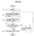
- the second embodiment differs from the first embodiment in that, not the white-shading correcting circuit 41, but the CPU of the body control unit 22 performs the creation of the white-shading data and the calculation of the white-shading correction.
- the gate signal XSHGATE is supplied from the controller 23 so as to read a predetermined constant range of the second read roller 12 (step S1). This realizes the reading means and the reading step.
- step S2 an average value of a first block 1, i.e., first L lines, of image data read from the second read roller 12 is obtained (step S2). Subsequently, the average value is stored in a predetermined area of a RAM (not shown in the figure) (step S3).
- step S3 When the step S2 and the step S3 are not performed to a last block m yet (N in step S4), the step S2 and the step S3 are repeated to a following block (step S6) until the step S2 and the step S3 are performed to the last block m (Y in the step S4).
- the step S2 realizes an averaging means and an averaging step.
- the read range of the second read roller is at least one round thereof, that in this case the length of each block is arranged smaller than the length of the reference-white read surface 13, and that the read range of the second read roller 12 is set as a range exceeding one round, for example, two rounds or three rounds, and the length of each block is so set that, when the read range exceeding one round is divided into the blocks, a fractional block is created in each round thereof.
- step S5 realizes a peak-value determining means and a peak-value determining step.
- the average value of image data is calculated with respect to lines at intervals of one or several lines, for example, every second line, or every third line, in each of the blocks 1 to m.
- step S2 of FIG.10 is performed as shown in FIG.11.
- step S11 it is judged whether or not the present line is an odd-numbered line, one by one from a first line in each block.
- step S12 image data of the present line is stored in a predetermined area of a RAM in the body control unit 22 (step S12).
- step S11 and the step S12 are not performed to a last (L-th) line in the present block yet (N in step S13)
- step S11 and the step S12 are repeated to a following line (step S14) until the step S11 and the step S12 are performed to the last line in the present block (Y in the step S13).
- step S15 an average value of the image data of the odd-numbered lines stored in the RAM is calculated (step S15).
- the third embodiment differs from the first and second embodiments in that the second read roller 12 does not have the shape as described with reference to FIG.3, but has such a shape that a cross-section thereof perpendicular to the central axis A is a substantially complete round, as shown in FIG.12, and that the reference-white read surface 13 is not formed.
- the creation of the white-shading data may be performed either by the white-shading data creating circuit 42 as in the first embodiment or by the CPU of the body control unit 22 as in the second embodiment.
- the read range of the second read roller is at least one round thereof, and that the read range of the second read roller 12 is set as a range exceeding one round, for example, two rounds or three rounds, and the length of each block is so set that, when the read range exceeding one round is divided into the blocks, a fractional block is created in each round thereof.
- the average value of image data is calculated with respect to lines at intervals of one or several lines, for example, every second line, or every third line, in each of the blocks 1 to m.
- the fourth embodiment differs from the first to third embodiments in that the image scanner 1 does not comprise the second image-reading unit 4, the subject-copy-setting unit 5, the subject-copy-delivering unit 6, the subject-copy-conveying path 7, the conveying rollers 8, the second contact glass 10, the first read roller 11, and the second read roller 12, as shown in FIG.13, in which only the first image-reading unit 3 with the first contact glass 9 reads the image of the subject copy D.
- a first carriage 51, a second carriage 52 and a lens unit 53 form a scanning optical system.
- the first carriage 51 comprises a light source used for exposing the subject copy D and a first reflective mirror.
- the second carriage 52 comprises a second reflective mirror and a third reflective mirror.
- the lens unit 53 is used for forming an image on the CCD 3a which is a photoelectric converting element.
- a reference-white plate (a reference-white member) 54 is provided as a reference white used for creating the white-shading data.
- the first image-reading unit 3 reads a predetermined constant range of the reference-white plate 54 by using the CCD 3a. This realizes a reading means and a reading step.
- the creation of the white-shading data may be performed either by the white-shading data creating circuit 42 as in the first embodiment or by the CPU of the body control unit 22 as in the second embodiment. In this case, a read range of the reference-white plate 54 is preferred to be as large as possible.
- the average value of image data is calculated with respect to lines at intervals of one or several lines, for example, every second line, or every third line, in each of the blocks 1 to m.
- the second read roller 12 or the reference-white plate 54 is read as a reference white, and then the read image data is divided into the m blocks, each block including the L lines.
- This process may be replaced with the following process.
- each of the blocks 1 to m includes L lines, and the starting line of each block is shifted from the starting line of a preceding block by one line.
- a simple average value of image data in the L lines is obtained (by a calculation based on the foregoing expression (1)), and then a peak value is obtained as white-shading data from among the simple average values obtained for the m blocks with respect to each pixel (by calculations based on the foregoing expressions (2) to (4)).
- the above-mentioned moving average values may be calculated by shifting the start of each block by a plurality of lines. However, it is preferred that the moving average values are-calculated by shifting the start of each block by one line, as described above, because this improves the precision of selecting image data of an unstained part of the second read roller 12 or the reference-white plate 54 as the white-shading data.
Landscapes
- Engineering & Computer Science (AREA)
- Multimedia (AREA)
- Signal Processing (AREA)
- Facsimile Image Signal Circuits (AREA)
- Facsimile Scanning Arrangements (AREA)
- Image Input (AREA)
- Optical Systems Of Projection Type Copiers (AREA)
Applications Claiming Priority (4)
| Application Number | Priority Date | Filing Date | Title |
|---|---|---|---|
| JP2000266106 | 2000-09-01 | ||
| JP2000266106 | 2000-09-01 | ||
| JP2001075636A JP4148655B2 (ja) | 2000-09-01 | 2001-03-16 | 画像読取装置、画像形成装置及び白基準データ作成方法 |
| JP2001075636 | 2001-03-16 |
Publications (3)
| Publication Number | Publication Date |
|---|---|
| EP1187458A2 true EP1187458A2 (de) | 2002-03-13 |
| EP1187458A3 EP1187458A3 (de) | 2004-08-11 |
| EP1187458B1 EP1187458B1 (de) | 2011-02-16 |
Family
ID=26599123
Family Applications (1)
| Application Number | Title | Priority Date | Filing Date |
|---|---|---|---|
| EP01307355A Expired - Lifetime EP1187458B1 (de) | 2000-09-01 | 2001-08-30 | Bildlesevorrichtung und -Verfahren mit Weisschattierungskorrektur |
Country Status (5)
| Country | Link |
|---|---|
| US (1) | US6891648B2 (de) |
| EP (1) | EP1187458B1 (de) |
| JP (1) | JP4148655B2 (de) |
| DE (1) | DE60144041D1 (de) |
| HK (1) | HK1043006B (de) |
Cited By (1)
| Publication number | Priority date | Publication date | Assignee | Title |
|---|---|---|---|---|
| EP2323364A3 (de) * | 2009-11-11 | 2011-07-13 | Ricoh Company, Ltd | Bildabtastvorrichtung und Bilderzeugungsvorrichtung |
Families Citing this family (55)
| Publication number | Priority date | Publication date | Assignee | Title |
|---|---|---|---|---|
| JP2003087531A (ja) * | 2001-09-12 | 2003-03-20 | Seiko Epson Corp | 画像読み取り装置及び画像読み取り方法 |
| US7286717B2 (en) * | 2001-10-31 | 2007-10-23 | Ricoh Company, Ltd. | Image data processing device processing a plurality of series of data items simultaneously in parallel |
| JP2003230010A (ja) | 2001-11-30 | 2003-08-15 | Ricoh Co Ltd | 画像処理装置及び画像処理方法 |
| JP2003348342A (ja) * | 2002-02-28 | 2003-12-05 | Ricoh Co Ltd | 画像処理装置及び画像形成装置 |
| US7327497B2 (en) * | 2002-05-14 | 2008-02-05 | Canon Kabushiki Kaisha | Image reading apparatus, control method therefor, and program |
| KR100464545B1 (ko) * | 2003-04-15 | 2005-01-03 | 삼성전자주식회사 | 화상 스캐닝 장치 및 그의 쉐이딩 보정 방법 |
| JP2004336453A (ja) * | 2003-05-08 | 2004-11-25 | Ricoh Co Ltd | 複写機、画像処理システム、プログラム及び記憶媒体 |
| JP2004336487A (ja) * | 2003-05-08 | 2004-11-25 | Ricoh Co Ltd | ファクシミリ装置、プログラム及び記憶媒体 |
| JP2004341760A (ja) * | 2003-05-15 | 2004-12-02 | Ricoh Co Ltd | 画像形成装置、プログラム及び記憶媒体 |
| JP2004357190A (ja) * | 2003-05-30 | 2004-12-16 | Ricoh Co Ltd | 画像読取装置 |
| US8471852B1 (en) | 2003-05-30 | 2013-06-25 | Nvidia Corporation | Method and system for tessellation of subdivision surfaces |
| JP4310143B2 (ja) * | 2003-07-25 | 2009-08-05 | 株式会社リコー | 画像処理装置 |
| TWM262936U (en) * | 2004-04-30 | 2005-04-21 | Avision Inc | Multiple-background device for a scanner and a calibration device utilizing the same principle |
| JP4580718B2 (ja) * | 2004-09-03 | 2010-11-17 | 株式会社リコー | 画像読み取り装置およびシェーディング補正方法 |
| US7889251B1 (en) * | 2005-06-08 | 2011-02-15 | National Semiconductor Corporation | Method and device for white level calibration |
| US7525693B2 (en) * | 2005-08-15 | 2009-04-28 | Kabushiki Kaisha Toshiba | Image reading apparatus and image reading method |
| US8571346B2 (en) * | 2005-10-26 | 2013-10-29 | Nvidia Corporation | Methods and devices for defective pixel detection |
| US7750956B2 (en) * | 2005-11-09 | 2010-07-06 | Nvidia Corporation | Using a graphics processing unit to correct video and audio data |
| US8588542B1 (en) | 2005-12-13 | 2013-11-19 | Nvidia Corporation | Configurable and compact pixel processing apparatus |
| US8737832B1 (en) * | 2006-02-10 | 2014-05-27 | Nvidia Corporation | Flicker band automated detection system and method |
| US8594441B1 (en) | 2006-09-12 | 2013-11-26 | Nvidia Corporation | Compressing image-based data using luminance |
| US8723969B2 (en) * | 2007-03-20 | 2014-05-13 | Nvidia Corporation | Compensating for undesirable camera shakes during video capture |
| US8724895B2 (en) * | 2007-07-23 | 2014-05-13 | Nvidia Corporation | Techniques for reducing color artifacts in digital images |
| JP4968930B2 (ja) * | 2007-08-03 | 2012-07-04 | キヤノン株式会社 | 画像処理装置、画像補正方法、画像処理方法及びプログラム |
| US8570634B2 (en) * | 2007-10-11 | 2013-10-29 | Nvidia Corporation | Image processing of an incoming light field using a spatial light modulator |
| US9177368B2 (en) * | 2007-12-17 | 2015-11-03 | Nvidia Corporation | Image distortion correction |
| US8780128B2 (en) * | 2007-12-17 | 2014-07-15 | Nvidia Corporation | Contiguously packed data |
| JP2009177310A (ja) * | 2008-01-22 | 2009-08-06 | Kyocera Mita Corp | 画像読取装置及び画像形成装置 |
| US8698908B2 (en) * | 2008-02-11 | 2014-04-15 | Nvidia Corporation | Efficient method for reducing noise and blur in a composite still image from a rolling shutter camera |
| US9379156B2 (en) * | 2008-04-10 | 2016-06-28 | Nvidia Corporation | Per-channel image intensity correction |
| JP2009272891A (ja) * | 2008-05-07 | 2009-11-19 | Ricoh Co Ltd | 画像読取装置、画像形成装置、画像読取方法及び画像形成方法 |
| US8311360B2 (en) * | 2008-11-13 | 2012-11-13 | Seiko Epson Corporation | Shadow remover |
| US8373718B2 (en) * | 2008-12-10 | 2013-02-12 | Nvidia Corporation | Method and system for color enhancement with color volume adjustment and variable shift along luminance axis |
| US8749662B2 (en) * | 2009-04-16 | 2014-06-10 | Nvidia Corporation | System and method for lens shading image correction |
| US8698918B2 (en) * | 2009-10-27 | 2014-04-15 | Nvidia Corporation | Automatic white balancing for photography |
| JP5736682B2 (ja) * | 2010-07-16 | 2015-06-17 | 株式会社リコー | 画像読取装置、画像形成装置および画像データ補正方法 |
| JP5652063B2 (ja) * | 2010-09-02 | 2015-01-14 | 株式会社リコー | 画像読取装置、画像形成装置及びシェーディング補正方法 |
| JP2012089922A (ja) | 2010-10-15 | 2012-05-10 | Canon Inc | 画像読取装置 |
| JP2012192628A (ja) * | 2011-03-16 | 2012-10-11 | Seiko Epson Corp | 記録装置、記録システム、記録装置の制御方法、及び、プログラム |
| JP2013132042A (ja) | 2011-11-25 | 2013-07-04 | Ricoh Co Ltd | 画像検査装置、画像形成装置、画像検査方法及びプログラム |
| US9798698B2 (en) | 2012-08-13 | 2017-10-24 | Nvidia Corporation | System and method for multi-color dilu preconditioner |
| US9508318B2 (en) | 2012-09-13 | 2016-11-29 | Nvidia Corporation | Dynamic color profile management for electronic devices |
| US9307213B2 (en) | 2012-11-05 | 2016-04-05 | Nvidia Corporation | Robust selection and weighting for gray patch automatic white balancing |
| JP6040714B2 (ja) | 2012-11-06 | 2016-12-07 | 株式会社リコー | 自動原稿搬送装置、自動原稿搬送装置を備えた画像読取装置および画像形成装置 |
| US9418400B2 (en) | 2013-06-18 | 2016-08-16 | Nvidia Corporation | Method and system for rendering simulated depth-of-field visual effect |
| US9826208B2 (en) | 2013-06-26 | 2017-11-21 | Nvidia Corporation | Method and system for generating weights for use in white balancing an image |
| US9756222B2 (en) | 2013-06-26 | 2017-09-05 | Nvidia Corporation | Method and system for performing white balancing operations on captured images |
| JP6241094B2 (ja) * | 2013-06-28 | 2017-12-06 | 株式会社リコー | 画像読取装置、画像形成装置及び画像読取り方法 |
| KR101920816B1 (ko) | 2013-07-08 | 2018-11-21 | 한화테크윈 주식회사 | 쉐이딩 보정이 가능한 화이트 발란스 방법, 그리고 이에 적용되는 장치 |
| JP6331805B2 (ja) * | 2014-07-16 | 2018-05-30 | 富士ゼロックス株式会社 | 画像読取装置 |
| JP2017079374A (ja) * | 2015-10-19 | 2017-04-27 | 株式会社リコー | 画像読取装置、画像形成装置、およびシェーディングデータ処理方法 |
| US10091393B2 (en) * | 2017-01-19 | 2018-10-02 | Kabushiki Kaisha Toshiba | Document conveying device, document reading apparatus, and document conveying method |
| JP7196644B2 (ja) | 2019-01-30 | 2022-12-27 | 株式会社リコー | 傾き検出装置、読取装置、画像処理装置および傾き検出方法 |
| JP7131415B2 (ja) | 2019-01-31 | 2022-09-06 | 株式会社リコー | 傾き検出装置、読取装置、画像処理装置および傾き検出方法 |
| JP7424076B2 (ja) | 2020-01-29 | 2024-01-30 | 株式会社リコー | 画像処理装置、画像処理システム、撮像装置、画像処理方法およびプログラム |
Citations (1)
| Publication number | Priority date | Publication date | Assignee | Title |
|---|---|---|---|---|
| JPH1170062A (ja) | 1997-08-29 | 1999-03-16 | Sanyo Electric Co Ltd | 床用吸込具 |
Family Cites Families (13)
| Publication number | Priority date | Publication date | Assignee | Title |
|---|---|---|---|---|
| JPH0834543B2 (ja) | 1986-06-30 | 1996-03-29 | 株式会社リコー | スキャナ |
| JP2566611B2 (ja) * | 1988-04-06 | 1996-12-25 | 大日本スクリーン製造 株式会社 | 平均最大値を利用したシェーディング補正用基準データの生成方法 |
| JPH01233874A (ja) * | 1988-05-09 | 1989-09-19 | Ricoh Co Ltd | 画像読取装置 |
| US4987485A (en) * | 1988-12-22 | 1991-01-22 | Minolta Camera Kabushiki Kaisha | Image reading apparatus with improved output correction of image signal |
| JPH0322751A (ja) * | 1989-06-20 | 1991-01-31 | Toshiba Corp | 読取り装置 |
| US5371613A (en) * | 1991-02-22 | 1994-12-06 | Canon Kabushiki Kaisha | Image reading apparatus |
| JP2960611B2 (ja) | 1992-07-13 | 1999-10-12 | 三田工業株式会社 | シェーディング補正方法およびシェーディング補正装置 |
| US5644409A (en) | 1994-01-13 | 1997-07-01 | Mita Industrial Co., Ltd. | Shading correcting method and shading correcting apparatus for use in image forming apparatuses |
| US6246484B1 (en) * | 1995-11-22 | 2001-06-12 | Canon Kabushiki Kaisha | Image reading apparatus and information processing apparatus having image reading function |
| JP3308790B2 (ja) * | 1996-01-17 | 2002-07-29 | キヤノン株式会社 | プリント方法およびプリント装置 |
| KR100199476B1 (ko) * | 1996-12-07 | 1999-06-15 | 윤종용 | 원고 크기 감지 장치 및 방법 |
| JP4536170B2 (ja) * | 1996-12-27 | 2010-09-01 | シャープ株式会社 | 撮像装置 |
| JPH1175062A (ja) * | 1997-06-30 | 1999-03-16 | Ricoh Co Ltd | 画像読取装置 |
-
2001
- 2001-03-16 JP JP2001075636A patent/JP4148655B2/ja not_active Expired - Fee Related
- 2001-08-29 US US09/940,589 patent/US6891648B2/en not_active Expired - Lifetime
- 2001-08-30 EP EP01307355A patent/EP1187458B1/de not_active Expired - Lifetime
- 2001-08-30 DE DE60144041T patent/DE60144041D1/de not_active Expired - Lifetime
-
2002
- 2002-04-10 HK HK02102669.4A patent/HK1043006B/zh not_active IP Right Cessation
Patent Citations (1)
| Publication number | Priority date | Publication date | Assignee | Title |
|---|---|---|---|---|
| JPH1170062A (ja) | 1997-08-29 | 1999-03-16 | Sanyo Electric Co Ltd | 床用吸込具 |
Cited By (2)
| Publication number | Priority date | Publication date | Assignee | Title |
|---|---|---|---|---|
| EP2323364A3 (de) * | 2009-11-11 | 2011-07-13 | Ricoh Company, Ltd | Bildabtastvorrichtung und Bilderzeugungsvorrichtung |
| US8514452B2 (en) | 2009-11-11 | 2013-08-20 | Ricoh Company, Ltd. | Image scanning apparatus and image forming apparatus |
Also Published As
| Publication number | Publication date |
|---|---|
| HK1043006A1 (en) | 2002-08-30 |
| HK1043006B (zh) | 2011-08-26 |
| DE60144041D1 (de) | 2011-03-31 |
| EP1187458A3 (de) | 2004-08-11 |
| US20020054374A1 (en) | 2002-05-09 |
| EP1187458B1 (de) | 2011-02-16 |
| JP2002152510A (ja) | 2002-05-24 |
| JP4148655B2 (ja) | 2008-09-10 |
| US6891648B2 (en) | 2005-05-10 |
Similar Documents
| Publication | Publication Date | Title |
|---|---|---|
| US6891648B2 (en) | Image-reading device performing a white-shading correction by obtaining a peak value of average values of image data and read from a reference-white member in blocks as white-shading data | |
| US9241089B2 (en) | Image forming apparatus and method for scaling image data by a correction pixel | |
| JP2010148061A (ja) | 画像読取装置、等倍度調整方法 | |
| JP5531690B2 (ja) | 画像読取装置及び画像形成装置 | |
| EP1533747B1 (de) | Druckvorrichtung mit in der Sub-Abtastrichtung versetzten LED-Köpfen | |
| JP5544795B2 (ja) | 画像読取装置、画像形成装置及び制御プログラム | |
| JP4580718B2 (ja) | 画像読み取り装置およびシェーディング補正方法 | |
| KR100572293B1 (ko) | 화상 형성 장치 | |
| KR100418044B1 (ko) | 화상 형성 장치 | |
| JP2002185720A (ja) | 画像読み取り装置及び画像読み取り方法 | |
| JP5206588B2 (ja) | 画像処理装置、画像形成装置、画像処理方法および画像処理プログラム | |
| JP2009016915A (ja) | 原稿読取装置およびそれを備える画像形成装置、ならびに画像処理方法 | |
| JP2004112297A (ja) | 画像読み取り装置および画像形成装置 | |
| JP4494680B2 (ja) | 白シェーディングデータ作成装置、画像読取装置および画像形成装置 | |
| JP4001323B2 (ja) | 画像形成装置 | |
| JP3466879B2 (ja) | 画像読取装置 | |
| JPH08265521A (ja) | 画像読取装置と画像形成装置およびその制御方法 | |
| JP4114778B2 (ja) | 画像形成装置 | |
| JP2006060698A (ja) | 画像読取装置 | |
| JPH07203194A (ja) | 画像形成装置 | |
| JP2006060693A (ja) | 画像読取装置 | |
| JP2003125177A (ja) | 画像読取装置及び画像形成装置 | |
| JP2004356666A (ja) | 原稿読取装置、画像形成装置及び画像形成方法 | |
| JP2005210492A (ja) | 原稿読取装置、その補正方法及び画像形成装置 | |
| JP2005051295A (ja) | 原稿読取装置および画像形成装置 |
Legal Events
| Date | Code | Title | Description |
|---|---|---|---|
| PUAI | Public reference made under article 153(3) epc to a published international application that has entered the european phase |
Free format text: ORIGINAL CODE: 0009012 |
|
| AK | Designated contracting states |
Kind code of ref document: A2 Designated state(s): AT BE CH CY DE DK ES FI FR GB GR IE IT LI LU MC NL PT SE TR |
|
| AX | Request for extension of the european patent |
Free format text: AL;LT;LV;MK;RO;SI |
|
| RAP1 | Party data changed (applicant data changed or rights of an application transferred) |
Owner name: RICOH COMPANY LTD. |
|
| RAP1 | Party data changed (applicant data changed or rights of an application transferred) |
Owner name: RICOH COMPANY, LTD. |
|
| PUAL | Search report despatched |
Free format text: ORIGINAL CODE: 0009013 |
|
| AK | Designated contracting states |
Kind code of ref document: A3 Designated state(s): AT BE CH CY DE DK ES FI FR GB GR IE IT LI LU MC NL PT SE TR |
|
| AX | Request for extension of the european patent |
Extension state: AL LT LV MK RO SI |
|
| 17P | Request for examination filed |
Effective date: 20040917 |
|
| AKX | Designation fees paid |
Designated state(s): DE FR GB |
|
| RBV | Designated contracting states (corrected) |
Designated state(s): DE FR GB |
|
| 17Q | First examination report despatched |
Effective date: 20090120 |
|
| GRAP | Despatch of communication of intention to grant a patent |
Free format text: ORIGINAL CODE: EPIDOSNIGR1 |
|
| RTI1 | Title (correction) |
Free format text: IMAGE-READING DEVICE AND METHOD FOR PERFORMING A WHITE-SHADING CORRECTION BY OBTAINING A PEAK VALUE OF AVERAGE VALUES OF IMAGES DATA READ FROM A REFERENCE-WHITE MEMBER IN BLOCKS |
|
| RTI1 | Title (correction) |
Free format text: IMAGE-READING DEVICE AND METHOD FOR PERFORMING A WHITE-SHADING CORRECTION |
|
| RIN1 | Information on inventor provided before grant (corrected) |
Inventor name: KAWAMOTO, HIROYUKI Inventor name: NOMIZU, YASUYUKI Inventor name: NARA, WATARU Inventor name: INOUE, YOSHIKAZU Inventor name: HATTORI, HITOSHI Inventor name: KUBO, HIROSHI Inventor name: SANO, MOTOYA Inventor name: FUKANO, HIROSHI |
|
| GRAS | Grant fee paid |
Free format text: ORIGINAL CODE: EPIDOSNIGR3 |
|
| GRAA | (expected) grant |
Free format text: ORIGINAL CODE: 0009210 |
|
| AK | Designated contracting states |
Kind code of ref document: B1 Designated state(s): DE FR GB |
|
| REG | Reference to a national code |
Ref country code: GB Ref legal event code: FG4D |
|
| REF | Corresponds to: |
Ref document number: 60144041 Country of ref document: DE Date of ref document: 20110331 Kind code of ref document: P |
|
| REG | Reference to a national code |
Ref country code: DE Ref legal event code: R096 Ref document number: 60144041 Country of ref document: DE Effective date: 20110331 |
|
| REG | Reference to a national code |
Ref country code: HK Ref legal event code: GR Ref document number: 1043006 Country of ref document: HK |
|
| PLBE | No opposition filed within time limit |
Free format text: ORIGINAL CODE: 0009261 |
|
| STAA | Information on the status of an ep patent application or granted ep patent |
Free format text: STATUS: NO OPPOSITION FILED WITHIN TIME LIMIT |
|
| 26N | No opposition filed |
Effective date: 20111117 |
|
| REG | Reference to a national code |
Ref country code: DE Ref legal event code: R097 Ref document number: 60144041 Country of ref document: DE Effective date: 20111117 |
|
| REG | Reference to a national code |
Ref country code: FR Ref legal event code: PLFP Year of fee payment: 16 |
|
| REG | Reference to a national code |
Ref country code: FR Ref legal event code: PLFP Year of fee payment: 17 |
|
| PGFP | Annual fee paid to national office [announced via postgrant information from national office to epo] |
Ref country code: GB Payment date: 20170822 Year of fee payment: 17 Ref country code: DE Payment date: 20170822 Year of fee payment: 17 Ref country code: FR Payment date: 20170822 Year of fee payment: 17 |
|
| REG | Reference to a national code |
Ref country code: DE Ref legal event code: R119 Ref document number: 60144041 Country of ref document: DE |
|
| GBPC | Gb: european patent ceased through non-payment of renewal fee |
Effective date: 20180830 |
|
| PG25 | Lapsed in a contracting state [announced via postgrant information from national office to epo] |
Ref country code: DE Free format text: LAPSE BECAUSE OF NON-PAYMENT OF DUE FEES Effective date: 20190301 |
|
| PG25 | Lapsed in a contracting state [announced via postgrant information from national office to epo] |
Ref country code: FR Free format text: LAPSE BECAUSE OF NON-PAYMENT OF DUE FEES Effective date: 20180831 |
|
| PG25 | Lapsed in a contracting state [announced via postgrant information from national office to epo] |
Ref country code: GB Free format text: LAPSE BECAUSE OF NON-PAYMENT OF DUE FEES Effective date: 20180830 |