EP1180556B1 - Verfahren zur Herstellung eines Doppelpolgewebes - Google Patents
Verfahren zur Herstellung eines Doppelpolgewebes Download PDFInfo
- Publication number
- EP1180556B1 EP1180556B1 EP00117599A EP00117599A EP1180556B1 EP 1180556 B1 EP1180556 B1 EP 1180556B1 EP 00117599 A EP00117599 A EP 00117599A EP 00117599 A EP00117599 A EP 00117599A EP 1180556 B1 EP1180556 B1 EP 1180556B1
- Authority
- EP
- European Patent Office
- Prior art keywords
- weft
- binding
- threads
- binding warp
- group
- Prior art date
- Legal status (The legal status is an assumption and is not a legal conclusion. Google has not performed a legal analysis and makes no representation as to the accuracy of the status listed.)
- Expired - Lifetime
Links
Images


Classifications
-
- D—TEXTILES; PAPER
- D03—WEAVING
- D03D—WOVEN FABRICS; METHODS OF WEAVING; LOOMS
- D03D27/00—Woven pile fabrics
- D03D27/02—Woven pile fabrics wherein the pile is formed by warp or weft
- D03D27/10—Fabrics woven face-to-face, e.g. double velvet
Definitions
- the invention relates to a method for producing a Doppelpolgewebes on a double pole weaving machine with at least two weft insertion planes, using weft yarns, filler warp yarns and binder warp yarns for the education of the basic goods of lower and upper goods as well as of choirs of pile threads per warp course for the formation of the patterned Pol harsh between both basic commodities, their each not musterernde Pole threads in the basic goods of the upper and / or lower fabric largely are stretched involved and their respective mustering pile threads in exchange between weft threads of the upper fabric and the lower fabric clamped become; the weft threads being in at least two different weft insertion planes, in at least two-part rapport, at least as Back shot or as a shot in both registered basic goods become;
- Each basic item groups against each other in the warp direction offset arranged binder warp threads are assigned, wherein the binding warp threads a group within a weave repeat all wefts embrace externally with respect
- the binding chains are regularly arranged in groups of two binding warp threads. Each group is assigned to a warp course. Each warp course has each such a group of binding warp threads, at least one Golfkettfaden and a choir of pile threads.
- a group of binding warp threads is characterized in that it retains all back shots and all inner shots in its area of effect on the stretched-in filler chain and on the stretched-in dead poles within its weave repeat. It is customary to let the individual binding warp threads of a group within a repeat follow a specific weave pattern.
- the binding warp threads Due to the fact that only a single warp beam is usually available for the binding warp threads on a double-pole weaving machine, the binding warp threads have regularly been woven according to a uniform weave pattern, so that the length of bonding and thus the tension of all the warp threads of a group within a repeat could be kept constant , The experts regularly orientate it to the fact that a repeat size of four weft insertion cycles is not exceeded to ensure the uniform thread tension of running from a single warp beam binding warps.
- the exit direction of the pole leg regularly deviates up to 10 ° and more from the vertical position to the base product out.
- Such an inclined position of the pole legs regularly leads to certain, required treading properties can be ensured only by increasing the polar density and / or by increasing the pole height. Both measures to ensure the desired treading require a considerable amount of pile material.
- the cost of the carpet thus produced are correspondingly high.
- Another disadvantage of this asymmetric bond is that the recovery capacity of the pole cover is given at partially high stress - for example, through the feet of furniture - in insufficient extent.
- intensive brushing operations and the like can not be ruled out. As a rule, however, such pressure points leave lasting, visible deformations in the pole surface. Due to the inclined position of the pole legs, such woven carpets can not be strung together in the object area use. The different angles of reflection of the incident light, which arise as a function of the respective weaving direction, give the viewer the impression that there are color errors.
- the tread elasticity is limited.
- the recoverability of the pole cover after Load is limited and the suitability of the carpets for the contract area is not given.
- they have an intermediate shot Tied pole handle a determined in practical experiments pull-out, which is only about 25% of those Polhenkel that over one Backshot are tied off. The durability of the carpet is low.
- the pattern resolution is limited because one and the same pile thread always in two Polhenkel must train successive pole rows.
- This Poleinitati leads to blurred pattern contours.
- the on The pole shank bonded to the intermediate shank differs depending on the load From the side and irregularly crowded between different colored pole handle.
- the object of the present invention is to find a method for fixing the basic goods by means of binding warp threads, which guarantees on the one hand a largely vertical and stable integration of the pole legs in the base goods, which makes it possible to produce a carpet fabric with high pile density and ensures that the amount of material in the field of basic goods can be significantly reduced. It is also desirable that the measures found - with reduced Polmaterial intercept - equal or better impact properties can be ensured in a carpet produced in this way.
- the smaller lateral deflection of the binding warp threads in conjunction with a possible then symmetrical loading of the weft threads, means that they are also fixed immovably in the base fabric in the area of the inner shots.
- the pole legs held or guided on these weft threads are hardly deflected. They occur regularly with the appropriate orientation of the reed perpendicular to the basic product. It becomes possible to realize the usually required treading properties even with a lower pile height and even with possibly lower pile density.
- the consumption of binding warp threads - depending on the binding finally chosen - is reduced significantly. The use of an additional warp beam on the loom is avoided.
- the modification of the method according to claim 2 makes it possible to increase the length of the holding sections, without having to provide additional measures for the setting of individual shots.
- the measure according to claim 3 enables a further, significant reduction in the consumption of binding warp threads with reliable securing integration of all weft threads and in securing a uniform bond length of all binding warp threads. It has been found that the tension of the binding warp threads can be maintained even over longer sections even if one of the binding warp threads follows more than four turns of a section with a different type of binding.
- the bias and the elasticity of the binding warp threads and the individual load by the warp stop guards are sufficient to always secure the minimum tension of the binding warp threads.
- the weft yarns of large thickness used in carpet weaving machines in the usual way do not necessarily require a setting in each warp course for securing their position. It is possible to use only a single binding warp in each warp course and distribute the binding warp threads of a group - according to the current state of knowledge - up to four, adjacent warp courses. The material saving is very clear. The pole density in the weft direction and warp direction can thus be increased additionally.
- the measure according to claim 4 ensures a further reduction of Need for binding warp threads.
- the use of balancing sections allows, in particular in the selection of symmetrical bonding pattern for the Binding chain on the one hand uniform binding lengths of the binding warp threads and On the other hand, a non-binding binding of the pole thighs leading Interior shots.
- the binding variant according to claim 5 allows in addition to a high shot and Polêt in the warp direction, also an optimal support of the pole leg in the weft direction.
- the shaft drive can also be realized here with a conventional eccentric machine. A sufficient stability of the basic product can be achieved even if one arranges only one binding warp in each warp course.
- the method according to claim 6 enables an additional saving of the binding warp thread.
- Claim 7 shows a possibility in which one can realize with the inventive method large clamping lengths of the pole legs.
- Claim 8 describes a procedure in which a somewhat higher consumption of binding warp threads is taken in purchase in the interest of a higher stability of the basic product. The upright poles are guaranteed here as well.
- the claim 9 describes a nearly equivalent solution variant to claim. 5
- the variant according to claim 10 allows vertical Polschenkel in securing a very high stability of the basic product and a high pile density in the warp direction. A restriction on the density in the weft direction is prevented by the distribution of the binding warp threads on four warp courses.
- Claim 11 describes a method with which - similar properties are achieved, as described in relation to claim 10. Independent claim 12 leads to the same effects with regard to the saving of binding warp threads as the method according to claim 1. However, for the upright binding of the pole legs, the clamping of the woven part of the binding warp threads is not or only to a limited extent available here.
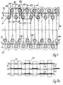
- the double carpet shown in Figure 1 consists of an upper and a lower base fabric, the top fabric OW and the lower fabric UW, and from, between the upper and lower basic fabric regularly changing patterning pile threads PM, which after weaving midway between upper OW and Unterware UW be separated.
- Each of the basic goods OW, UW contains warp yarns FK extending in the warp direction and non-patterning pile yarns aligned parallel thereto, which are referred to below as Totpole PT or Totpolstrang.
- These two thread groups FK, PT are held on the outside by back shots SR and on the inside by inside shots SI.
- the position of the back SR and inner shots SI is fixed by binding warp threads B (in FIG. 1: B1, B2).
- the binding warp B are arranged in groups.
- the size of the group normally varies between two (e.g., B1, B2) and four (e.g., B13 through B16) binding warps B.
- the number of binding warps B of a group depends on how many threads are needed at least Within a binding repeat R, all back shots SR and inside shots SI are tied once to the basic fabric. (Neighboring groups may also complement each other with respect to one or more binding sites.)
- a binding repeat of the binding warp threads B we usually find at least one holding section Y and at least one compensating section Z.
- the first holding section Y1 of the binding warp B1 of the group B1, B2 shown in FIG. 1 begins after the inside shot SI shown on the left above.
- this binding warp thread B1 is guided to the following inside shot SI and from there in the same plane to the next inside shot SI. If all binding warp threads B1, B2 of the group with the same binding length bind, the binding repeat of a group would already be terminated here. In the present case, however, the second binder warp B2 binds in another way. He changes from one, the first-mentioned pair of weft yarns opposite weft yarn to the next, the three weft entries is entered later.
- binding warp B2 brings the necessary longitudinal tension in the ground fabric and ensures that the back shots SR, the pole handle wear and the inner shots SI, the pole handle lead, pull so closely together that a tilt of the pole handle is avoided with certainty.
- both binding warp threads B1, B2 change their binding type twice within a repeat R - if necessary in a special change section W.
- the holding portion Y1, Y2 In both types of bonding, the holding portion Y1, Y2 and also extends the respective compensation section Z1, Z3 over three weft insertion cycles. Of the Overall repeat is due to the change sections W z. B. 20 or 28 Weft insertion cycles. After every three or five shots change regularly two binding warps B1, B2 from the back plane to the inside or vice versa.
- the size of the repeat R and the individual binding sections X1, X2 should be chosen so that a temporary loosening of individual Bind warp threads B1, B2 of a group can be avoided with certainty.
- the tension of the binding warp B should be before entering the shedding zone be monitored and a voltage value of 2 to 4 N not below.
- the binding warps B1, B2 of the group can in the present case to two be distributed adjacent Kettadose K1, K2 (Fig. 2). They hold despite This distribution the relatively bulky back shots SR on the filling chain FK and inner shots SI sufficiently safe at the Totpolstrfiten PT in the respective basic product OW or UW.
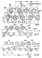
- FIGS. 2 to 8 binding forms are shown on upper goods OW, in which the basic goods have only backseam SR and inner shots SI.
- FIGS. 9 to 15 show basic goods, that is, top goods OW, which also have intermediate shots SZ (SZ1, SZ2, SZ3).
- FIG. 2 shows a binding as also described with reference to FIG has been. Only the changing sections W are positioned here somewhat differently and designed. The changing sections W are in Fig. 2 in addition to the Holding portions Y1, Y2 and the balancing sections Z1, Z2 provided.
- the binding variant of Fig. 3 shows a regular, paired setting the back SR and inside shots SI. It fulfills the inventive Objective with very simple means.
- the first involved Backshot SR retains its predefined position until the second back shot of this pair is struck.
- the one in front of the couple Binding of the back shots of the last inward shot SI brought up Holding section Y3 is clamped in the already finished tissue so that in This thread section hardly any elastic component will be effective can move the last registered back shot SR sideways could.
- the pole legs are not distracted and stand almost vertically in the basic product.
- the type of binding according to FIG. 4 shows larger sections X3, X4 with different types of binding of the binding warp threads B5, B6, B7, B8.
- Two binding warp threads B5, B6 regularly bind in pairs via back shots SR or inside shots SI.
- Their holding sections Y4 and their compensating sections Z4 extend over five weft insertion cycles each.
- the two binding warp threads B7, B8 bind in each case only via one shot, one back shot SR or one inside shot SI.
- Fig. 5 shows a form of bonding in which the individual binding warp threads B9, B10, B11, B12 set almost symetrically and regularly according to a single type of binding. Distraction of the pole legs in any direction is reliably avoided and the individual binding warp threads B9, B10, B11, B12 of a group are preferably arranged in pairs in adjacent warp courses K1, K2. It is also possible to arrange these binding warp threads B9, B10, B11, B12 individually in four adjacent warp courses.
- the holding sections Y5 comprise five weft entries, while the compensating sections Z5 are completed after every three tours.
- FIG. 6 is substantially comparable to FIG. Of the The difference is that the binding warp threads B13, B14, B15, B16 instead tie over single shots over weft pairs.
- this version is a very high fabric density with absolutely vertical orientation of Polschenkel reached. With a repeat size of 16, there are nine tours on the holding section Y6 and seven tours on the compensation section Z6. It is possible, when using appropriate weft threads the Need to significantly reduce binding warp when the individual binder warp threads a group spread over several warp courses.
- the binding of Figure 7 differs from Figure 6 in that the number that of a binding warp B17, B18, B19, B20 in the area of the back shots SR and in the area of inner shots Si is further increased.
- the Bonding with other binding warps B17, B18, B19, B20 become a group the back shots SR or inside shots SI each in plain weave fixed.
- the holding portion Y7 and also the compensation portion Z7 extends each about seven shots.
- FIGS. 9 to 11 show the regular incorporation of the weft threads by binding warp threads B25, B26, B27, wherein the binding warp threads fix the weft threads SR, Si in mutual exchange almost symmetrically almost uniformly in a manner consistent with the repeat R9, R10, R11.
- the binding warp yarns B25, B26, B27, B28 of each of these basic goods may be arranged in one to four warp courses with respect to a group.
- a binding repeat R12 of a binding warp B29, B30 consists of holding sections Y12 and compensating sections Z12 with different types of weave in the manner of plain weave between inner SI and intermediate shot SZ3 or between back SR and intermediate shot SZ3. All back shots SR and all inside shots Si are symmetrically loaded by the binding warp threads B29, B30.
- the binding length of the binding warp threads B29, B30 of this group is compensated by the example of FIG. 2 by two alternating sections W.
- the binding of Figure 13 is substantially similar to the binding of Figure 7. However, the changing sections W are shortened.
- the holding sections Y13 extend over five weft insertion cycles; the balancing sections Z13 also.
- the additional intermediate shots SZ1 which press the filling chain FK against the back shots SR, ensure a slight curvature of the filling chain FK, which additionally hinders the sliding of the back shots SR in the warp direction.
- individual back shots SR are individually loaded in the warp direction, they retain their original position in conjunction with the adjacent shots. They thus allow an exact alignment of the pole legs perpendicular to the base product.
- Figs. 14 and 15 include further modifications to Figs. 7 and 8.
- the Intermediate shots SZ2, SZ3 serve here for the additional fixation of the Rükkenschüsse SR, without the binding warp threads B34, B35, B36 or B37, B38, B39 regularly cover the entire cross-section of the basic product OW.
- the summation of internal stresses in the binding chains B1, B2 is avoided by the loop friction in connection with the friction by the clamping action within the finished fabric.
- With the distribution of the binder warps B1 and B2 in adjacent warp courses not only the density in the weft direction but also the density in the warp direction can be increased. At the densest points in the tissue, crossing points of the binding warp threads B1, B2 are avoided.
- the back shots are SR and inner shots, respectively SI within the holding sections Y17 (and also in the balancing sections Y7 Fig. 7) in each case in their plane by plain weave together held.
- All back shots SR and also all inside shots SI are by at least one diagonal binding warp thread section fixed to the filling chain FK or kept at the Totpolen PT.
- the basic commodity is on this Way very stable.
- the longitudinal forces (in the direction of the chain) in this system In addition, through the diagonal thread section within the holding section Y17 applied. Again, the clamping forces affect this thread section in the finished tissue positively.
- the back and Inner shots SR, Si remain in the finished fabric in the position in which they are at the stop (stop direction A) are positioned.
- FIG. 18 shows a binding variant according to the invention, which despite the Asymmetry of the bond pattern a vertical involvement of the pole legs allows.
- the binding warp B40 becomes after its binding at the inside shot SI4 within holding section Y18 over eight weft insertion cycles in the area of the Totpole PT and the FK filling chain. In this It is stretched in the finished fabric and simultaneously clamped on all sides. The applied by him clamping force acts in the direction of attack A. all positioned in his sphere of action back shots alike. Although the inner shots SI in this bond seemingly straight in opposite Direction burdened, one put in practice no Shift in that direction.
- the cause is very likely in that the clamping forces on the long holding section Y18 within of the finished fabric are so large that a shift in the Interior shots not taking place in a repeated shotgun.
- the Pole handles are also perpendicular to this asymmetric bond regularly from the basic commodity.
Landscapes
- Engineering & Computer Science (AREA)
- Textile Engineering (AREA)
- Woven Fabrics (AREA)
Description
Eine Gruppe von Bindekettfäden ist dadurch gekennzeichnet, dass sie innerhalb ihres Bindungsrapportes alle Rückenschüsse und alle Innenschüsse in ihrem Wirkungsbereich an der gestreckt eingebundenen Füllkette und an den gestreckt eingebundenen Totpolen hält.
Es ist dazu üblich, die einzelnen Bindekettfäden einer Gruppe innerhalb eines Rapportes einem bestimmten Bindungsmuster folgen zu lassen.
Die Fachleute orientieren dabei regelmäßig darauf, dass zur Sicherung der einheitlichen Fadenspannung der von einem einzigen Kettbaum ablaufenden Bindekettfäden eine Rapportgröße von vier Schußeintragszyklen nicht überschritten wird.
In der Praxis wurde an Doppelteppichwebmaschinen für die Herstellung der Grundgewebe regelmäßig eine sog. zweitourige Ripps-Bindung verwendet (vergl. Hans Osswald, "Die Teppichindustrie" 1965, Melliand Textilberichte, Heidelberg, Seiten 111 -114 und Seiten 119 bis 121). Bei dieser sog. Ripps-2/2-Bindung erstreckte sich in einer der beiden Grundwaren regelmäßig ein Bindekettfaden diagonal von einem Innenschuss zu einem drei Touren später eingetragenen Rückenschuss und von dort in der unmittelbar folgenden Tour wieder zurück zu einem Innenschuss.
Eine derartige Bindung garantiert bereits eine brauchbare Qualität der Einbindung der Polschenkel. Der Schußdichte sind jedoch relatv enge Grenzen gesetzt.
Die asymmetrisch eingebundene Bindekette führt dazu, dass die die Polhenkel tragenden und stützenden Schüsse in Kettrichtung entlang der Füllkette bzw. entlang der Totpole verschoben werden. Die Austrittsrichtung der Polhenkel weicht regelmäßig bis zu 10° und mehr von der senkrechten Lage zur Grundware hin ab.
Eine solche geneigte Lage der Polschenkel führt regelmäßig dazu, dass bestimmte, geforderte Tritteigenschaften nur durch die Erhöhung der Poldichte und/oder durch die Vergrößerung der Polhöhe gewährleistet werden können. Beide Maßnahmen zur Gewährleistung der gewünschten Tritteigenschaften erfordern einen erheblichen Aufwand an Polmaterial. Die Kosten für den so hergestellten Teppich sind entsprechend hoch.
Ein weiterer Nachteil dieser asymmetrischen Bindung besteht darin, dass die Erholungsfähigkeit der Poldecke bei partiell starker Belastung - zum Beispiel durch die Füße von Möbeln - in nur ungenügendem Maße gegeben ist.
Für die Beseitigung von Druckstellen sind intensive Bürstvorgäne und dergl. nicht auszuschließen. In der Regel hinterlassen solche Druckstellen aber bleibende, sichtbare Verformungen in der Poloberfläche.
Durch die geneigte Lage der Polschenkel lassen sich derart gewebte Teppiche nicht aneinandergereiht im Objektbereich verwenden. Die unterschiedlichen Reflexionswinkel des einfallenden Lichtes, die in Abhängigkeit von der jeweiligen Webrichtung entstehen, führen beim Betrachter zu dem Eindruck, dass Farbfehler vorliegen.
Bei einer bestimmten Anordnung der nacheinander oder gleichzeitig eingetragenen Schüsse im Bereich eines Bindungsrapportes, führte diese Maßnahme hinsichtlich der Ausrichtung der Polschenkel nur mit Einschränkungen zum Erfolg. (vergl. DE 574 920). Der Materialeinsatz erhöhte sich zudem deutlich.
Die Herstellung sehr dichter Polwaren war deshalb bisher aus den genannten Gründen regelmäßig der einschützigen Webtechnik vorbehalten, wo nicht jeder Polhenkel an einem Rückenschuss gebunden wird.
Es wird auch angestrebt, dass durch die gefundenen Maßnahmen - bei reduziertem Polmaterialeinsatz - gleiche oder bessere Tritteigenschaften bei einem so hergestellten Teppich gewährleistet werden können.
Auch die geringere seitliche Auslenkung der Bindekettfäden führt in Verbindung mit einer dann möglichen, symmetrischen Belastung der Schussfäden dazu, dass dieselben auch im Bereich der Innenschüsse unverschieblich in der Grundware fixiert werden. Die an diesen Schussfäden gehaltenen bzw. geführten Polschenkel werden kaum abgelenkt. Sie treten bei entsprechender Ausrichtung des Webblattes regelmäßig senkrecht aus der Grundware hervor. Es wird möglich, auch bei geringerer Polhöhe und sogar bei ggfs. geringerer Poldichte die üblicherweise geforderten Tritteigenschaften zu realisieren. Gleichzeitig reduziert sich der Verbrauch an Bindekettfäden - in Abhängigkeit von der schließlich gewählten Bindung sehr deutlich. Die Verwendung eines zusätzlichen Kettbaumes an der Webmaschine wird vermieden.
Die Modifizierung des Verfahrens nach Anspruch 2 ermöglicht es, die Länge der Halteabschnitte zu vergrößern, ohne dass man für die Abbindung einzelner Schüsse zusätzlichen Maßnahmen vorsehen muss.
Die Maßnahme nach Anspruch 3 ermöglicht eine weitere, deutliche Reduzierung des Verbrauchs an Bindekettfäden bei zuverlässiger Sicherung Einbindung aller Schussfäden und bei der Sicherung einer einheitlichen Einbindelänge aller Bindekettfäden. Es hat sich gezeigt, das die Spannung der Bindekettfäden auch dann noch über längere Abschnitte aufrecht erhalten werden kann, wenn einer der Bindekettfäden über mehr als vier Touren einem Abschnitt mit unterschiedlicher Bindungsart folgt. Die Vorspannung und die Elastizität der Bindekettfäden sowie die Einzelbelastung durch die Kettfadenwächter reichen aus, um die Mindestspannung der Bindekettfäden stets zu sichern.
Die an Teppichwebmaschinen in üblicher Weise verwendeten Schußfäden großer Dicke benötigen für die Sicherung ihrer Lage nicht zwingend eine Abbindung in jedem Kettkurs. Es ist möglich, in jedem Kettkurs nur einen einzigen Bindekettfaden einzusetzen und die Bindekettfäden einer Gruppe - nach dem jetzigen Erkenntnisstand - auf bis zu vier, einander benachbarte Kettkurse zu verteilen. Die Materialeinsparung ist sehr deutlich. Die Poldichte in Schussrichtung und Kettrichtung kann so zusätzlich erhöht werden.
Eine ausreichende Stabilität der Grundware erreicht man auch dann, wenn man in jedem Kettkurs nur einen Bindekettfaden anordnet.
Das Verfahren nach dem Anspruch 6 ermöglicht eine zusätzliche Einsparung an Bindkettfaden.
Anspruch 7 zeigt eine Möglichkeit, bei der man auch mit dem erfindungsgemäßen Verfahren große Einspannlängen der Polschenkel realisieren kann. Anspruch 8 beschreibt eine Verfahrensweise, bei der im Interesse einer höheren Stabilität der Grundware ein etwas höherer Verbrauch an Bindekettfäden inkauf genommen wird. Die aufrecht stehenden Pole werden auch hier gewährleistet.
Der Anspruch 9 beschreibt eine nahezu gleichwertige Lösungsvariante zu Anspruch 5.
Die Variante nach Anspruch 10 ermöglicht senkrecht stehende Polschenkel bei Sicherung einer sehr hohen Stabilität der Grundware und einer hohen Poldichte in Kettrichtung. Einer Beschränkung hinsichtlich der Dichte in Schussrichtung beugt man durch die Verteilung der Bindekettfäden auf vier Kettkurse vor.
Der Anspruch 11 beschreibt ein Verfahren, mit dem - ähnliche Eigenschaften erzielt werden, wie sie in Bezug auf Anspruch 10 beschrieben wurden.
Der selbstständige Anspruch 12 führt hinsichtlich der Einsparung an Bindekettfäden zu gleichen Effekten wie das Verfahren nach Anspruch 1. Für das aufrechte Einbinden der Polschenkel steht hier jedoch das Klemmen des eingewebten Teiles der Bindekettfäden nicht oder nur begrenzt zur Verfügung.
- Fig. 1.
- einen Schnitt durch ein Doppelteppichgewebe entlang der Kettrichtung,
- Fig. 1a
- eine Draufsicht auf das Doppelteppichgewebe gemäß Fig. 1,
- Fig. 2.
- ein schematisches Bindungsbild einer der Grundwaren einer Oberware, mit unregelmäßigem Bindungsmuster der Bindkettfäden,
- Fig. 3.
- eine Darstellung analog Fig. 2 mit regelmäßigem Bindungsrapport,
- Fig. 4.
- ein schematisches Bindungsbild mit in großen Abschnitten unregelmäßig bindenden Bindekettfäden in zwei einander benachbarten Kettkursen,
- Fig. 5.
- eine Darstellung analog Fig. 2 mit regelmäßig symmetrisch bindenden Bindekettfäden, die paarweise in zwei benachbarten Kettkursen angeordnet sind,
- Fig. 6.
- eine Darstellung analog Fig. 5 mit paarweise gebundenen Rükken- und Innenschüssen,
- Fig. 7.
- die Darstellung eines Bindungsmusters mit wechselnder Leinwandbindung über je drei Innenschüsse und je drei Rückenschüsse,
- Fig. 8.
- eine Darstellung analog Fig. 7 mit verlängerter Leinwand bindung im Bereich der Rücken- und Innenschüsse,
- Fig. 9.
- eine Darstellung eines Obergewebes mit zusätzlichem Zwischenschuss und regelmäßiger Führung der Bindeketten und einer Verteilung der Bindeketten auf zwei Kettkurse,
- Fig. 10.
- eine Darstellung entsprechend Fig. 9 mit einer modifizierten Anordnung der Zwischenschüsse,
- Fig. 11.
- eine Darstellung analog zu Fig. 9 mit einer dritten Variante der Anordnung der Zwischenschüsse, wobei die Gruppe der Bindekettfäden aus vier Bindekettfäden besteht und dieselben zwei Kettkursen zugeordnet sind,
- Fig. 12.
- eine Darstellung einer Oberware mit der Schussanordnung nach Fig. 11, wobei die Bindekettfäden abschnittsweise in Leinwandbindung die Rücken- und Zwischenschüsse umschlingen und im folgendem Abschnitt die Zwischen- und die Innenschüsse gleichermaßen bindet,
- Fig. 13.
- zeigt eine Darstellung analog Fig. 7, wobei ein zusätzlicher Zwischenschuss vorgesehen ist,
- Fig. 14 und 15
- Modifikationen der Bindung nach Fig.13,
- Fig. 16
- ein Wirkungsschema der paarigen Schussbindung bei Rückenschüssen an einer Oberware analog zu Fig. 1 und 2,
- Fig. 17
- ein Wirkungsschema bei der Anwendung von Leinwandbindung an den Rückenschüssen an einer Oberware und
- Fig. 18
- ein Wirkungsschema bei asymmetrisch gestreckter Einbindung der Bindekettfäden unter Nutzung ihrer Klemmwirkung in dem fertigen Gewebe einer Oberware.
Jede der Grundwaren OW, UW enthält in Kettrichtung verlaufende Füllkettfäden FK und parallel dazu ausgerichtete, nicht musternde Polfäden, die im folgenden als Totpole PT oder Totpolstrang bezeichnet werden.
Diese beiden Fadenguppen FK, PT werden an der Außenseite durch Rückenschüsse SR und an der Innenseite durch Innenschüsse SI gehalten. Die Lage der Rücken- SR und Inennschüsse SI wird durch Bindekettfäden B, (in Fig. 1: B1, B2) fixiert. Die Bindekettfäden B sind gruppenweise angeordnet. Die Größe der Gruppe schwankt normalerweise zwischen zwei (z. B. B1, B2) und vier (z. B. B13 bis B16) Bindekettfäden B. Die Anzahl der Bindekettfäden B einer Gruppe richtet sich danach, wie viele Fäden mindestens benötigt werden, um innerhalb eines Bindungsrapportes R alle Rückenschüsse SR und Innenschüsse SI an der Grundware je einmal zu binden. (Einander benachbarte Gruppen können sich auch gegenseitig hinsichtlich einer oder mehrerer Bindungsstellen ergänzen.)
In einen Bindungsrapport der Bindekettfäden B finden wir in der Regel mindestens einen Halteabschnitt Y und mindestens einen Ausgleichsabschnitt Z.
Der erste Halteabschnitt Y1 des Bindekettfades B1 der in Fig. 1 gezeigten Gruppe B1, B2 beginnt nach dem links oben gezeigten Innenschuss SI. Er schließt den oberen, linken Rückenschuss SR1 und dann den zweiten Rükkenschuss SR2 ein. Im folgenden ersten Ausgleichsabschnitt Z1 wird dieser Bindekettfaden B1 zum folgenden Innenschuss SI und von dort in der gleichen Ebene bis zum nächsten Innenschuss SI geführt. Binden alle Bindekettfäden B1, B2 der Gruppe mit der gleichen Einbindungslänge, wäre der Bindungsrapport einer Gruppe hier bereits beendet.
Im vorliegenden Falle bindet der zweite Bindekettfaden B2 jedoch in anderer Weise. Er wechselt jeweils von einem, dem erstgenannten Paar Schussfäden gegenüber liegenden Schussfaden zum nächsten, der drei Schusseinträge später eingetragen wird. Dieser Bindekettfaden B2 bringt die nötige Längsspannung in das Grundgewebe und sorgt dafür, dass die Rückenschüsse SR, die Polhenkel tragen und die Innenschüsse SI, die Polhenkel führen, so eng aneinander ziehen, dass eine Schräglage der Polhenkel mit Sicherheit vermieden wird.
Damit die Einbindelänge beider Bindekettfäden B1, B2 innerhalb eines Rapportes gewährleistet bleibt, wechseln beide Bindekettfäden B1, B2 zweimal innerhalb einbes Rapportes R - ggfs. in einem besonderen Wechselabschnitt W gegenseitig ihre Bindungsart.
Die Fig. 9 bis 15 zeigen dagegen Grundwaren, d. h. Oberwaren OW, die auch Zwischenschüsse SZ (SZ1, SZ2, SZ3) aufweisen.
Deren Halteabschnitte Y4 und deren Ausgleichsabschnitte Z4 erstecken sich über je fünf Schusseintragszyklen. Die beiden Bindekettfäden B7, B8 binden jeweils nur über je einen Schuss, einen Rückenschuss SR oder einen Innenschuss SI.
Der Halteabschnitt Y4' erstreckt sich über fünf Schusseinträge, während dar Ausgleichsabschnitt Z4' sieben Schusseinträge umfasst. Es ist zweckmäßig diese Bindungsarten nach bestimmten Abschnitten - wie in Fig 2 erwähnt - gegenseitig zu wechseln. Möchte man derartige Wechsel W vermeiden, dann müssen die beiden unterschiedlich bindenden Paare von Bindekettfäden B5, B6 bzw. B7, B8 von zwei verschiedenen Kettbäumen abgezogen werden.
Die Halteabschnitte Y5 umfassen fünf Schusseinträge, während die Ausgleichabschnitte Z5 nach je drei Touren abgeschlossen sind.
In den Fig. 9 bis 11 ist die regelmäßige Einbindung der Schussfäden durch Bindekettfäden B25, B26, B27 gezeigt, wobei die Bindekettfäden nach einheitlicher Bindungsart mit dem Rapport R9, R10, R11 nahezu symmetrisch die Schussfäden SR, Si im gegenseitigen Wechsel einzeln fixieren.
Die Bindekettfäden B25, B26, B27, B28 jeder dieser Grundwaren können, bezogen auf eine Gruppe in ein bis vier Kettkursen angeordnet sein.
Die Bindung nach Fig.13 ist im wesentlichen vergleichbar mit der Bindung nach Fig.7. Die Wechselabschnitte W sind jedoch verkürzt.
Die Halteabschnitte Y13 erstrecken sich über fünf Schusseintragszyklen; die Ausgleichsabschnitte Z13 ebenfalls.
Die zusätzlichen Zwischenschüsse SZ1, die die Füllkette FK gegen die Rükkenschüsse SR drücken, sorgen für eine leichte Wölbung der Füllkette FK, die das Gleiten der Rückenschüsse SR in Kettrichtung zusätzlich behindert. Obwohl einzelne Rückenschüsse SR in Kettrichtung einzeln belastet sind, behalten sie ihre ursprüngliche Lage im Verbund mit den benachbarten Schüssen. Sie ermöglichen so ein exaktes Ausrichten der Polschenkel senkrecht zur Grundware.
Die Ursache dafür ist im Detail variabel. Die dabei wirkenden Prinzipien darzustellen, ist Gegenstand der Fig. 16 bis 18.
In der Bindungsform nach Fig. 16 wird die symmetrische Belastung eines Schussfadenpaares durch die Bindekette B1 genutzt. Die notwendigen Kräfte für das Aneinanderhalten des Schussfadenpaares SR1 und SR2 in Kettrichtung liefert die Bindekette B2 mit ihren diagonal gerichteten Halte- Y2 und Ausgleichsabschnitten Z2. Das Summieren innerer Spannungen in den Bindeketten B1, B2 wird durch die Umschlingungsreibung in Verbindung mit der Reibung durch die Klemmwirkung innerhalb des fertigen Gewebes vermieden. Mit der Verteilung der Bindekettfäden B1 und B2 in einander benachbarten Kettkursen kann man nicht nur die Dichte in Schussrichtung sondern auch die Dichte in Kettrichtung erhöhen. An den dichtesten Stellen im Gewebe werden Kreuzungsstellen der Bindekettfäden B1, B2 vermieden.
Die nahezu senkrechte Ausrichtung der Polfadenschenkel ist auch mit dieser Variante realisierbar. Die Ergebnisse beim Erreichen einer hohen Poldichte sind ähnlich zu bewerten, wenn eine bestimmte Rapportlänge gewährleistet ist. Die Wirkungen hinsichtlich der Einsparung an Material für die Bindekette insgesamt sind auch bei dieser Variante voll wirksam.
- OW
- Oberware
- UW
- Unterware
- K, K1, K2
- Kettkurs
- S
- Schussfäden, allgemein
- SR
- Rückenschuss
- Sl
- Innenschuss
- SZ
- Zwischenschuss, allgemein
- SZ1
- Zwischenschuss, über Innenschuss
- SZ2
- Zwischenschuss, unter Rückenschuss
- SZ3
- Zwischenschuss, zw. zwei Paaren von Innen- und Rückenschuss
- FK
- Füllkette
- P
- Polfäden, allgemein
- PM
- Polfäden, musternd
- PT
- Polfäden, nicht musternd bzw Totpole
- B
- Bindekettfäden, allgemein
- B1, B2
- Bindekettfäden, Gruppe
- B3, B4
- Bindekettfäden, Gruppe
- B5, B6, B7, B8
- Bindekettfäden, Gruppe
- B9, B10, B11, B12
- Bindekettfäden, Gruppe
- B13, B14, B15, B16
- Bindekettfäden, Gruppe
- B17, B18, B19, B20
- Bindekettfäden, Gruppe
- B21, B22, B23, B24
- Bindekettfäden, Gruppe
- B25, B26, B27, (B28)
- Bindekettfäden, Gruppe
- B29, B30
- Bindekettfäden, Gruppe
- B31, B32, B33,
- Bindekettfäden, Gruppe
- B34, B35, B36
- Bindekettfäden, Gruppe
- B37, B38, B39
- Bindekettfäden, Gruppe
- B40, B41
- Bindekettfäden, Gruppe
- R
- Bindungrapport, allgemein
- R+Ziffer der Fig.
- Bindungsrapport, spezifisch
- X1, X2
- Bindungsabschnitt
- W
- Wechselabschnitt
- Y+Ziffer der Fig.
- Halteabschnitt
- Z+Ziffer der Fig.
- Ausgleichsabschnitt
- A
- Anschlagrichtung
Claims (12)
- Verfahren zur Herstellung eines Doppelteppichgewebes auf einer Doppelpolwebmaschine mit mindestens zwei Schusseintragsebenen, unter Verwendungwobei die Schussfäden (SR, SI), in beiden Grundwaren (OW, UW), mindestens als Rückenschuss (SR) und als Innenschuss (SI) eingetragen werden;von Schussfäden (SR, SI), Füllkettfäden (FK) und Bindekettfäden (B) für die Ausbildung der Grundwaren in Form der Unterware (UW) und der Oberware (OW), sowievon Choren von Polfäden (P) pro Kettkurs (K) für die Ausbildung der gemusterten Polschicht zwischen beiden Grundwaren,deren jeweils nicht musternde Polfäden (PT) in den Grundwaren der Ober- und/oder Unterware weitgehend gestreckt eingebunden sind undderen jeweils musternde Polfäden (PM) im Wechsel zwischen Schussfäden (S) der Oberware und Schussfäden der Unterware aufgespannt werden;
wobei in jeder Grundware (OW, UW) Gruppen von Bindekettfäden (B) nach einem vorgegebenen Rapport (R) Webfächer ausbildend zugeführt werden,
wobei die Bindekettfäden (B) einer Gruppe innerhalb eines Bindungsrapportes (R) alle Schussfäden (SR, SI), bezogen auf eine Grundware (OW, UW), von außen bzw. von innen umgreifen,
wobei jeder Bindekettfaden (B) einer Gruppe in einem Bereich, beginnend nach seiner jeweils letzten Bindung an einem Innenschuss (SI) und endend mit der darauf folgenden, letzten Bindung an einem Rückenschuss (SR) unter Ausbildung eines Halteabschnittes (Y) und anschließend in einem Ausgleichsabschnitt (Z) geführt wird und
wobei die Rapporte (R) der Bindekettfäden (B) so gestaltet sind, dass die Einbindungslänge der Bindekettfäden (B) einer Gruppe innerhalb jedes Rapportes (R) untereinander ausgeglichen werden,
dadurch gekennzeichnet, dass jeder musternde Polfaden (PM) in jeder der beiden Grundwaren (OW, UW) ausschließlich über einen Rückenschuss (SR) aufgespannt wird,
dass der Bindungsrapport (R) einer Gruppe von Bindekettfäden (B) größer ist als sechs Schusseintragszyklen,
dass die Summe der Schusseintragszyklen aller Halteabschnitte (Y) einer Gruppe von Bindekettfäden (B) größer ist als sechs Schusseintragszyklen und
dass im Durchschnitt mindestens nach jedem dritten Schusseintragszyklus ein Bindekettfaden (B) der Gruppe zwischen einem Rückenschuss (SR) und einem Innenschuss (SI) oder umgekehrt wechselt. - Verfahren nach Anspruch 1, dadurch gekennzeichnet, dass die Gruppe aus drei oder mehreren Bindekettfäden (B) besteht.
- Verfahren nach Anspruch 1 oder 2, dadurch gekennzeichnet, dass sich die Bindekettfäden (B) einer Gruppe auf mindestens zwei einander benachbarte Kettkurse (K1, K2) verteilen.
- Verfahren nach Anspruch 1, dadurch gekennzeichnet, dass mindestens einer der Bindekettfäden (B) einer Gruppe innerhalb des Halteabschnittes (Y2, Y3, Y6, Y7, Y8, Y12, Y13, Y14, Y15, Y17) mit zwei oder mehreren, einander nahe benachbarten Rückenschüssen (SR) bindet, bevor er in einem Ausgleichsabschnitt (Z) wieder mit Innenschüssen (SI) bindet.
- Verfahren nach Anspruch 1, dadurch gekennzeichnet, dass die Gruppe aus vier regelmäßig bindenden Bindekettfäden (z. B. B13, B14, B15, B16) besteht,
dass jeder Bindekettfaden (B)in einem Halteabschnitt (Y6) nach der Bindung über den letzten Innenschuss (SI) über vier Touren zwischen der Ebene der Rückenschüsse (SR) und der Ebene der Innenschüsse (SI) geführt wird, bevor er ein Paar einander benachbarter Rückenschüsse (SR) gleichsinnig übergreift, undin dem folgenden Ausgleichsabschnitt (Z6), nach der Bindung über vier Touren zwischen der Ebene der Innenschüsse (SI) und der Ebene der Rückenschüsse (SR), innen gleichsinnig über zwei einander nahe benachbarte Innnensch üsse (SI) geführt wird. - Verfahren nach Anspruch 1, dadurch gekennzeichnet, dass die Gruppe aus vier unregelmäßig bindenden Bindekettfäden (B29, B30; B31, B32, B33; B34, B35, B36; B 37, B38, B39) besteht,
dass jeder Bindekettfaden (B)in einem Halteabschnitt (Y) über mehrere einander benachbarte Rückenschüsse (SR) in Leinwandbindung bindet undin einem Ausgleichsabschnitt (Z) über mehrere einander benachbarte Innenschüsse (SI) in Leinwandbindung bindet. - Verfahren nach Anspruch 5, dadurch gekennzeichnet, dass zwischen der Ebene der Rückenschüsse (SR) und der Ebene der Innenschüsse (SI) in einer zusätzlichen Ebene Zwischenschüsse (SZ1, SZ2, SZ3) eingefügt sind und
dass wahlweise jeder Bindekettfaden (B) in den Halteabschnitten (Y12, Y14, Y15) sowie in den Ausgleichsabschnitten (Z12, Z14, Z15) während der Leinwandbindung auch an einem oder mehreren Zwischenschüssen bindet. - Verfahren nach Anspruch 1, dadurch gekennzeichnet, dass ein Bindekettfaden (B1) in einem ersten Halteabschnitt (Y1) über ein Paar einander benachbarter Rückenschüsse (SR), im folgenden ersten Ausgleichsabschnitt (Z1) über ein Paar einander benachbarter Innenschüsse (SI) bindet,
dass eben dieser Bindekettfaden (B1) in einen zweiten Halteabschnitt (Y2) über einen einzelnen Rückenschuss (SR) und anschließend in einem zweiten Ausgleichsabschnitt (Z2) über einen einzelnen Innenschuss (SI) bindet und
dass zwischen den gegenseitig wechselnden Bindungsarten zwei Wechselabschnitte (W) vorgesehen sind. - Verfahren nach Anspruch 1, dadurch gekennzeichnet, dass jeder Bindekettfaden (B) in einem regelmäßigen Wechsel, nach mindestens jeder dritten Tour wechselnd, über einen Rückenschuss (SR) bzw. über einen Innenschuss (SI) symmetrisch bindet.
- Verfahren nach Anspruch 1, dadurch gekennzeichnet, dass eine Gruppe aus vier Bindekettfäden (B40) besteht,
dass jeder Bindekettfaden (B40) in einem übereinstimmenden Rapport (R) über mindestens acht Schusseintragszyklen in dem Halteabschnitt (Y18) über mindestens vier Schusseintragszyklen zwischen den Rücken- (SR) und den Innenschüssen geführt (SI) und schließlich über mindestens einen Rückenschuss (SR6) bindet,
dass dieser Bindekettfaden (B40) in dem folgenden Ausgleichsabschnitt (Z18) in die Ebene der Innenschüsse wechselt und
dass die Bindekettfäden (B40) auf mindestens zwei einander benachbarte Kettkurse (K1, K2) paarweise verteilt sind. - Verfahren nach Anspruch 1, dadurch gekennzeichnet, dass jede Gruppe aus zwei Bindekettfäden (B3, B4) besteht,
dass jeder Bindekettfaden (B3, B4)im Bereich des Halteabschnittes (Y3) nach zwei neutralen Schusseinträgen zwischen Innen- und Rückenschüssen (SI, SR) zunächst außen über ein Paar einander benachbarter Rückenschüsse (SR) bindet und im Bereich des Ausgleichsabschnittes (Z3) nach einem unmittelbaren Wechsel in die Ebene der Innenschüsse (SI) innen über ein Paar einander benachbarter Innenschüsse (SI) bindet. - Verfahren zur Herstellung eines Doppelpolgewebes auf einer Doppelpolwebmaschine mit mindestens zwei Schusseintragsebenen, unter Verwendungwobei die Schussfäden (SR, SI) in mindestens zwei verschiedenen Schusseintragsebenen, in einem mindestens zweitourigem Rapport, mindestens als Rückenschuss (SR) oder als Innenschuss (SI) in beide Grundwaren (OW, UW) eingetragen werden;von Schussfäden (SR, SI), Füllkettfäden (FK) und Bindekettfäden (B) für die Ausbildung der Grundwaren von Unterware (UW) und der Oberware (OW) sowievon Choren von Polfäden (P) pro Kettkurs (K) für die Ausbildung der gemusterten Polschicht zwischen beiden Grundwaren,deren jeweils nicht musternde Polfäden (PT) in den Grundwaren der Ober- und/oder Schussfäden der Unterware weitgehend gestreckt eingebunden sind undderen jeweils musternde Polfäden (PM) im Wechsel zwischen Schussfäden (SR) der Oberware und der Unterware aufgespannt werden;
wobei jeder Grundware (OW, UW) Gruppen von in Kettrichtung gegeneinander versetzt angeordneten Bindekettfäden (B) zugeordnet sind,
wobei die Bindekettfäden (B) einer Gruppe innerhalb eines Bindungsrapportes (R) alle Schussfäden (SR, SI), bezogen auf eine Grundware (OW, UW), von außen umgreifen,
wobei jeder Bindekettfaden (B) einer Gruppe in einem Berich, beginnend nach seiner jeweils ersten Bindung an einem Rückenschuss (SR) und endend mit der darauf folgenden Bindung an dem ersten Innenschuss (SI) über einen Bindeabschnitt geführt ist und
wobei die Einbindungslänge der Bindekettfäden (B) einer Gruppe innerhalb des Bindungsrapportes (R) untereinander ausgeglichen ist,
dadurch gekennzeichnet, dass jeder musternde Polfaden (PM) in jeder der beiden Grundwaren (OW, UW) ausschließlich über einen Rückenschuss (SR) aufgespannt wird,
dass der Bindungsrapport (R) einer Gruppe von Bindekettfäden (B) größer ist als sechs Schusseintragszyklen,
dass die Summe der Schusseintragszyklen aller Bindeabschnitte einer Gruppe von Bindekettfäden (B) größer ist als sechs Schusseintragszyklen und
dass im Durchschnitt mindestens nach jedem dritten Schusseintragszylus mindestens ein Bindekettfaden (B) der Gruppe zwischen einem Rükkenschuss (SR) und einem Innenschuss (Sl) oder umgekehrt wechselt.
Priority Applications (3)
| Application Number | Priority Date | Filing Date | Title |
|---|---|---|---|
| EP00117599A EP1180556B1 (de) | 2000-08-16 | 2000-08-16 | Verfahren zur Herstellung eines Doppelpolgewebes |
| DE50011569T DE50011569D1 (de) | 2000-08-16 | 2000-08-16 | Verfahren zur Herstellung eines Doppelpolgewebes |
| US09/903,067 US6502605B2 (en) | 2000-08-16 | 2001-07-11 | Process for the production of a face-to-face carpet fabric |
Applications Claiming Priority (1)
| Application Number | Priority Date | Filing Date | Title |
|---|---|---|---|
| EP00117599A EP1180556B1 (de) | 2000-08-16 | 2000-08-16 | Verfahren zur Herstellung eines Doppelpolgewebes |
Publications (2)
| Publication Number | Publication Date |
|---|---|
| EP1180556A1 EP1180556A1 (de) | 2002-02-20 |
| EP1180556B1 true EP1180556B1 (de) | 2005-11-09 |
Family
ID=8169534
Family Applications (1)
| Application Number | Title | Priority Date | Filing Date |
|---|---|---|---|
| EP00117599A Expired - Lifetime EP1180556B1 (de) | 2000-08-16 | 2000-08-16 | Verfahren zur Herstellung eines Doppelpolgewebes |
Country Status (3)
| Country | Link |
|---|---|
| US (1) | US6502605B2 (de) |
| EP (1) | EP1180556B1 (de) |
| DE (1) | DE50011569D1 (de) |
Families Citing this family (9)
| Publication number | Priority date | Publication date | Assignee | Title |
|---|---|---|---|---|
| BE1015103A3 (nl) * | 2002-09-11 | 2004-10-05 | Wiele Michel Van De Nv | Werkwijze voor het weven van een poolweefsel. |
| EP1489210A1 (de) * | 2003-06-21 | 2004-12-22 | SCHÖNHERR Textilmaschinenbau GmbH | Verfahren zur Herstellung eines Doppelpolgewebes auf einer Doppelpolwebmaschine |
| EP1489211B1 (de) * | 2003-06-21 | 2006-12-20 | SCHÖNHERR Textilmaschinenbau GmbH | Verfahren zur Herstellung eines Doppelpolgewebes auf einer Doppelpolwebmaschine |
| US7520303B2 (en) * | 2005-06-24 | 2009-04-21 | N.V. Michel Van De Wiele | Method for weaving a fabric, fabric woven by means of such a method and weaving machine for weaving such a fabric |
| BE1016883A3 (nl) * | 2005-12-06 | 2007-09-04 | Wiele Michel Van De Nv | Werkwijze voor het vervaardigen van poolweefsels met hoge dichtheid. |
| FR2929623B1 (fr) * | 2008-04-03 | 2010-06-04 | Schonherr Textilmaschb | Procede de tissage pour realiser un tapis et tapis obtenu par un tel procede |
| EP2251467B1 (de) * | 2009-05-13 | 2013-08-07 | SCHÖNHERR Textilmaschinenbau GmbH | Verfahren zum gleichzeitigen Weben von zwei Gewebe, Gewebe das mit einem solchen Verfahren gewebt wird und Webmaschine bei der dieses Verfahren anwendbar ist. |
| WO2013041938A2 (en) * | 2011-09-22 | 2013-03-28 | Nv Michel Van De Wiele | Method for weaving a pile fabric |
| EP3702500B1 (de) * | 2019-02-26 | 2022-04-06 | STÄUBLI BAYREUTH GmbH | Verfahren zum weben von florgeweben und nach diesem verfahren gewebtes florgewebe |
Family Cites Families (8)
| Publication number | Priority date | Publication date | Assignee | Title |
|---|---|---|---|---|
| BE675494A (de) * | ||||
| DE574920C (de) | 1928-11-24 | 1935-05-17 | Karl Petzoldt | Jacquardmaschine |
| FR1401236A (fr) * | 1964-03-04 | 1965-06-04 | Librex Anstalt | Nouveau tapis tissé en double pièce et mode de tissage de ce tapis |
| US3612110A (en) * | 1968-10-22 | 1971-10-12 | Gerald Charles Wildi | Woven tapes |
| BE1004348A3 (nl) * | 1990-06-05 | 1992-11-03 | Wiele Michel Van De Nv | Werkwijze voor het vervaardigen van een dubbelstuktapijtweefsel, in een 2-schotbinding alsmede aldus verkregen weefsels. |
| EP0628649B1 (de) * | 1993-06-11 | 1998-01-07 | N.V. Michel Van de Wiele | Verfahren zum Herstellen von Doppelplüschgeweben |
| BE1012004A3 (nl) * | 1997-12-01 | 2000-04-04 | Wiele Michel Van De Nv | Werkwijze voor het vervaardigen van een poolweefsel met grove poolkettingdraden. |
| BE1012005A3 (nl) * | 1997-12-09 | 2000-04-04 | Wiele Michel Van De Nv | Werkwijze voor het weven van een poolweefsel met hoge pooldichtheid. |
-
2000
- 2000-08-16 EP EP00117599A patent/EP1180556B1/de not_active Expired - Lifetime
- 2000-08-16 DE DE50011569T patent/DE50011569D1/de not_active Expired - Lifetime
-
2001
- 2001-07-11 US US09/903,067 patent/US6502605B2/en not_active Expired - Lifetime
Also Published As
| Publication number | Publication date |
|---|---|
| US6502605B2 (en) | 2003-01-07 |
| EP1180556A1 (de) | 2002-02-20 |
| US20020036021A1 (en) | 2002-03-28 |
| DE50011569D1 (de) | 2005-12-15 |
Similar Documents
| Publication | Publication Date | Title |
|---|---|---|
| DE69733621T2 (de) | Papiermacher Verbundgewebe mit gepaarten Verbindungsschussfäden | |
| DE60318713T2 (de) | Formiersieb in form eines verbundgewebes mit dreifachem kettfaden | |
| DE1901379A1 (de) | Dreiachsiges Gewebe | |
| EP1180556B1 (de) | Verfahren zur Herstellung eines Doppelpolgewebes | |
| DE2631895A1 (de) | Schmales, schlauchfoermiges gewebe mit polsterwirkung | |
| DE60124813T2 (de) | Verfahren zum Herstellen von Doppelstück Plüschgewebe und nach diesem Verfahren hergestelltes Gewebe | |
| DE3930315C2 (de) | Gewebeband mit offenen Enden zur Verwendung in der Pressenpartie einer Papiermaschine | |
| DE2603855A1 (de) | Gewebebahn zur herstellung von versteifungseinlagen fuer kleidungsstuecke | |
| DE102005060301A1 (de) | Papiermaschinenbespannung | |
| EP1489210A1 (de) | Verfahren zur Herstellung eines Doppelpolgewebes auf einer Doppelpolwebmaschine | |
| DE2850474A1 (de) | Verbundgewebebahn und verfahren zu deren herstellung | |
| DE69913295T2 (de) | Verfahren zum Herstellen von Gewebe mit Rippenstruktur und nach diesem Verfahren hergestellte Gewebe | |
| EP0943711B1 (de) | Frottiergewebe mit Reliefeffekt und Verfahren zu dessen Herstellung | |
| DE60103091T2 (de) | Elastisches Gewebe für Kompressionsbandage, insbesondere Venöse | |
| EP1217114B1 (de) | Verfahren zur Herstellung eines Doppelpolgewebes | |
| DE4221376C2 (de) | Verfahren zur Herstellung von in der Florebene trennbarem Doppelflorgewebe | |
| DE19609492C2 (de) | Gewebe | |
| DE4325447C1 (de) | Verfahren zur Herstellung eines Doppelteppichgewebes | |
| DE4304227A1 (de) | Verfahren zur Herstellung eines Doppelteppichgewebes | |
| EP1489211B1 (de) | Verfahren zur Herstellung eines Doppelpolgewebes auf einer Doppelpolwebmaschine | |
| DE19504300B4 (de) | Gewebe, sowie Verfahren zu dessen Herstellung | |
| EP0063224B1 (de) | Verfahren zum Herstellen zweiseitiger textiler Flächengebilde und danach hergestelltes Flächengebilde | |
| DE4416396C1 (de) | Verfahren zur Herstellung eines Doppelteppichgewebes in Zweischußbindung auf einer Doppelfachwebmaschine | |
| EP0012991A1 (de) | Synthetisches Chemiefaser-Chenillegewebe | |
| DE4127164C2 (de) | Gewebter Spezialgurt für Wellpappenmaschinen |
Legal Events
| Date | Code | Title | Description |
|---|---|---|---|
| PUAI | Public reference made under article 153(3) epc to a published international application that has entered the european phase |
Free format text: ORIGINAL CODE: 0009012 |
|
| AK | Designated contracting states |
Kind code of ref document: A1 Designated state(s): AT BE CH CY DE DK ES FI FR GB GR IE IT LI LU MC NL PT SE Kind code of ref document: A1 Designated state(s): BE DE FR GB IT |
|
| AX | Request for extension of the european patent |
Free format text: AL;LT;LV;MK;RO;SI |
|
| 17P | Request for examination filed |
Effective date: 20020613 |
|
| AKX | Designation fees paid |
Free format text: BE DE FR GB IT |
|
| 17Q | First examination report despatched |
Effective date: 20040420 |
|
| GRAP | Despatch of communication of intention to grant a patent |
Free format text: ORIGINAL CODE: EPIDOSNIGR1 |
|
| GRAS | Grant fee paid |
Free format text: ORIGINAL CODE: EPIDOSNIGR3 |
|
| GRAA | (expected) grant |
Free format text: ORIGINAL CODE: 0009210 |
|
| AK | Designated contracting states |
Kind code of ref document: B1 Designated state(s): BE DE FR GB IT |
|
| PG25 | Lapsed in a contracting state [announced via postgrant information from national office to epo] |
Ref country code: IT Free format text: LAPSE BECAUSE OF FAILURE TO SUBMIT A TRANSLATION OF THE DESCRIPTION OR TO PAY THE FEE WITHIN THE PRESCRIBED TIME-LIMIT;WARNING: LAPSES OF ITALIAN PATENTS WITH EFFECTIVE DATE BEFORE 2007 MAY HAVE OCCURRED AT ANY TIME BEFORE 2007. THE CORRECT EFFECTIVE DATE MAY BE DIFFERENT FROM THE ONE RECORDED. Effective date: 20051109 Ref country code: GB Free format text: LAPSE BECAUSE OF FAILURE TO SUBMIT A TRANSLATION OF THE DESCRIPTION OR TO PAY THE FEE WITHIN THE PRESCRIBED TIME-LIMIT Effective date: 20051109 |
|
| REG | Reference to a national code |
Ref country code: GB Ref legal event code: FG4D Free format text: NOT ENGLISH |
|
| REF | Corresponds to: |
Ref document number: 50011569 Country of ref document: DE Date of ref document: 20051215 Kind code of ref document: P |
|
| GBV | Gb: ep patent (uk) treated as always having been void in accordance with gb section 77(7)/1977 [no translation filed] |
Effective date: 20051109 |
|
| PLBE | No opposition filed within time limit |
Free format text: ORIGINAL CODE: 0009261 |
|
| STAA | Information on the status of an ep patent application or granted ep patent |
Free format text: STATUS: NO OPPOSITION FILED WITHIN TIME LIMIT |
|
| 26N | No opposition filed |
Effective date: 20060810 |
|
| EN | Fr: translation not filed | ||
| PG25 | Lapsed in a contracting state [announced via postgrant information from national office to epo] |
Ref country code: FR Free format text: LAPSE BECAUSE OF FAILURE TO SUBMIT A TRANSLATION OF THE DESCRIPTION OR TO PAY THE FEE WITHIN THE PRESCRIBED TIME-LIMIT Effective date: 20061229 |
|
| PG25 | Lapsed in a contracting state [announced via postgrant information from national office to epo] |
Ref country code: FR Free format text: LAPSE BECAUSE OF FAILURE TO SUBMIT A TRANSLATION OF THE DESCRIPTION OR TO PAY THE FEE WITHIN THE PRESCRIBED TIME-LIMIT Effective date: 20051109 |
|
| PGFP | Annual fee paid to national office [announced via postgrant information from national office to epo] |
Ref country code: DE Payment date: 20180829 Year of fee payment: 19 |
|
| PGFP | Annual fee paid to national office [announced via postgrant information from national office to epo] |
Ref country code: BE Payment date: 20180827 Year of fee payment: 19 |
|
| REG | Reference to a national code |
Ref country code: DE Ref legal event code: R119 Ref document number: 50011569 Country of ref document: DE |
|
| REG | Reference to a national code |
Ref country code: BE Ref legal event code: MM Effective date: 20190831 |
|
| PG25 | Lapsed in a contracting state [announced via postgrant information from national office to epo] |
Ref country code: DE Free format text: LAPSE BECAUSE OF NON-PAYMENT OF DUE FEES Effective date: 20200303 |
|
| PG25 | Lapsed in a contracting state [announced via postgrant information from national office to epo] |
Ref country code: BE Free format text: LAPSE BECAUSE OF NON-PAYMENT OF DUE FEES Effective date: 20190831 |