EP1170714A1 - Kommunikationsanordnung einer mobilen einheit - Google Patents
Kommunikationsanordnung einer mobilen einheit Download PDFInfo
- Publication number
- EP1170714A1 EP1170714A1 EP00909719A EP00909719A EP1170714A1 EP 1170714 A1 EP1170714 A1 EP 1170714A1 EP 00909719 A EP00909719 A EP 00909719A EP 00909719 A EP00909719 A EP 00909719A EP 1170714 A1 EP1170714 A1 EP 1170714A1
- Authority
- EP
- European Patent Office
- Prior art keywords
- mobile unit
- terminal
- data
- mobile
- vehicle
- Prior art date
- Legal status (The legal status is an assumption and is not a legal conclusion. Google has not performed a legal analysis and makes no representation as to the accuracy of the status listed.)
- Granted
Links
Images


Classifications
-
- G—PHYSICS
- G08—SIGNALLING
- G08C—TRANSMISSION SYSTEMS FOR MEASURED VALUES, CONTROL OR SIMILAR SIGNALS
- G08C17/00—Arrangements for transmitting signals characterised by the use of a wireless electrical link
- G08C17/02—Arrangements for transmitting signals characterised by the use of a wireless electrical link using a radio link
-
- G—PHYSICS
- G08—SIGNALLING
- G08G—TRAFFIC CONTROL SYSTEMS
- G08G1/00—Traffic control systems for road vehicles
- G08G1/20—Monitoring the location of vehicles belonging to a group, e.g. fleet of vehicles, countable or determined number of vehicles
-
- G—PHYSICS
- G08—SIGNALLING
- G08C—TRANSMISSION SYSTEMS FOR MEASURED VALUES, CONTROL OR SIMILAR SIGNALS
- G08C2201/00—Transmission systems of control signals via wireless link
- G08C2201/90—Additional features
- G08C2201/91—Remote control based on location and proximity
-
- H—ELECTRICITY
- H04—ELECTRIC COMMUNICATION TECHNIQUE
- H04B—TRANSMISSION
- H04B7/00—Radio transmission systems, i.e. using radiation field
- H04B7/24—Radio transmission systems, i.e. using radiation field for communication between two or more posts
- H04B7/26—Radio transmission systems, i.e. using radiation field for communication between two or more posts at least one of which is mobile
Definitions
- the present invention relates to a communication device of a mobile unit for carrying out communications between a mobile unit, such as construction machine, and a terminal device.
- data such as travel location, service meter, amount of fuel, and engine speed, is required information from the standpoint of managing a vehicle.
- the invention disclosed in the above-mentioned publication is one that makes a connection between a management section and construction machine for unfettered two-way communications via communication means, and a data request is sent from the management section, data is extracted by the construction machine, and sent back to the management section. In this manner, the data of the construction machine side is collected at the requesting management section. Consequently, construction machine data can be obtained by a terminal of the management section side.
- the period of time during which a construction machine engine is not running (in other words, the period of time during which the power is OFF) is long.
- Fig. 21 shows the inside of the body of a construction machine.
- a battery 63 (rated voltage 24V), which is the power source, were, hypothetically, to be connected electrically to a communication terminal 56 at all times even while the engine is OFF, the battery 63 would not be charged by the alternator because the engine would not be running. Thus, the discharge of the battery 63 would proceed rapidly.
- the electrical connection between the battery 63 and communication terminal 56 were, hypothetically, to be OFF at all times while the engine is OFF, communications with the terminal would be impossible. For this reason, if there is a request for mobile unit information from the terminal side when the engine is OFF, it is impossible to respond to this.
- Japanese Patent Application Laid-open No. 10-68336 there is disclosed an invention, in which, when a signal requesting data relative to construction machine is received from a remote terminal, a construction machine internal controller is started up in response to signal reception, resulting in a state wherein download is possible, and start-stop is performed subsequent to the passage of a fixed period of time after a request signal is received.
- construction machine data cannot be sent to a remote terminal from the construction machine side in a state, wherein the remote terminal is not sending a request signal. That is, it is not possible to cope with a case in which construction machine transmits data on its own.
- a first invention is a communication device, wherein the mobile unit side sometimes transmits data on its own, and has as an object the enabling of communications while an engine is OFF, and, in addition, the suppressing of wasted power consumption.
- a third invention has as an object making it possible to know about an abnormal state occurring in a mobile unit, which cannot be constantly managed and monitored by the terminal side, and to accurately comprehend an operating state, and a resting state of a mobile unit.
- construction machines are very expensive, they are often rendered to be rented.
- the rental of construction machines utilizes a system called group rental.
- This is a system, whereby, due to the fact that there are various kinds of construction machines (small-sized hydraulic excavator, medium-sized hydraulic excavator, large-sized hydraulic excavator, and so forth), these many kinds of construction machines are shared by a plurality of business offices. For this reason, when a certain business office has a request from a client for a specific type of rental machine, and a business office does not have the pertinent type of construction machine, the business office can get another business office to loan it this specific type of construction machine, thereby not missing out on a business opportunity.
- each business office must reliably manage the storage and dispatch of its construction machine.
- An eleventh invention was devised with this fact in view, and has as an object making possible the real-time recording of the storage and dispatch history of a mobile unit, such as construction machine, and enabling storage and dispatch management to be performed reliably without mistakes.
- the delivery of construction machine to a rental customer, or the recovery of construction machine from a rental customer is carried out by loading the construction machine on a trailer. Because of the high cost of transportation by trailer, it is necessary to heighten the efficiency of trailer transport, and to keep transporting costs low. Further, it is necessary to increase rental opportunities and to raise business profits by speeding up delivery to a rental customer and recovery from a rental customer by heightening the efficiency of trailer transport.
- a thirteenth invention and a fourteenth invention were devised with this fact in view, and have as an object enhancing the transport efficiency of a mobile unit, such as construction machine.
- a first invention is a communication device of a mobile unit for communicating between a mobile unit and a terminal device, characterized in that the communication device, which enables communications with said terminal device when an electrical connection to a power source is ON, is provided in the mobile unit, and, in addition, means for intermittently turning ON and OFF an electrical connection between said power source and said communication device, when an engine of said mobile unit is OFF, is provided in the mobile unit
- communications are carried out between a mobile unit 31 and a terminal device 11.
- a communication device 56 provided in the mobile unit 31 becomes able to communicate with the terminal device 11 when an electrical connection with a power source 63 is ON.
- the period of time during which the engine is not running (in other words, the period of time during which the power is OFF) is long.
- the power source 63 is not recharged in accordance with engine operation, discharge progresses rapidly.
- the electrical connection with the communication device 56 is turned OFF while the power 63 is being OFF state, communications with the terminal device 11 is not possible, and it is not possible to respond to content sent from the terminal device side.
- a second invention is according to the first invention, and is characterized in that the above-mentioned ON/OFF means turns ON the electrical connection between the above-mentioned power source and the above-mentioned communication device at a predetermined period.
- a third invention is a communication device of a mobile unit for communicating between a mobile unit and a terminal device, characterized in that detecting means for detecting internal parameters of the mobile unit is provided in said mobile unit, and when a detection output of said detecting means becomes a specified value, data related to the mobile unit is sent to said terminal device from said mobile unit
- communications are carried out between a mobile unit 31 and a terminal device 11 as shown in Fig. 1, and when instructions requesting mobile unit 31 data are sent to the mobile unit 31 from the terminal device 11, mobile unit 31 data is sent to the terminal device 11 from the mobile unit 31.
- a mobile unit internal parameter for example, the engine start-up state
- detecting means for example, a sensor for detecting an alternator voltage value
- mobile unit information such as the location of construction machine or some other mobile unit 31, is to be acquired.
- the location of the mobile unit 31 is acquired by the terminal device 11 side when the engine is started up.
- the mobile unit 31 is moved illegally, since location data is acquired by the terminal device 11 side at that time, it is possible to deal appropriately with an abnormal situation.
- location data is not requested from the terminal device 11 side, a location history of each time the engine is started is acquired by the terminal device 11 side, making it possible to accurately comprehend the operating states and resting states of the mobile unit 31.
- a fourth invention is according to the third invention, and is characterized in that the above-mentioned detecting means is detecting means for detecting the fact that the engine of the above-mentioned mobile unit was started up, and when the above-mentioned engine is started up, mobile unit-related data is sent to the above-mentioned terminal device from the above-mentioned mobile unit.
- the above-mentioned detecting means is detecting means for detecting the fact that the engine of the above-mentioned mobile unit was started up, and when the above-mentioned engine is started up, mobile unit-related data is sent to the above-mentioned terminal device from the above-mentioned mobile unit.
- a fifth invention is according to the third invention, and is characterized in that the above-mentioned detecting means is detecting means for totaling the engine operating hours of the above-mentioned mobile unit, and when the total value of the above-mentioned engine operating hours either reaches a specified value, or increases by a specified amount, mobile unit-related data is sent to the above-mentioned terminal device from the above-mentioned mobile unit.
- the above-mentioned detecting means is detecting means for totaling the engine operating hours of the above-mentioned mobile unit, and when the total value of the above-mentioned engine operating hours either reaches a specified value, or increases by a specified amount, mobile unit-related data is sent to the above-mentioned terminal device from the above-mentioned mobile unit.
- a sixth invention is according to the third invention, and is characterized in that the above-mentioned detecting means is detecting means for detecting the location of the above-mentioned mobile unit, and when the location of the above-mentioned mobile unit changes, mobile unit-related data is sent to the above-mentioned terminal device from the above-mentioned mobile unit
- a seventh invention is according to the third invention, and is characterized in that the above-mentioned detecting means is detecting means for detecting the relative location of the above-mentioned mobile unit for a set range, and when the relative location of the above-mentioned mobile unit for a set range constitutes a specified relative location, mobile unit-related data is sent to the above-mentioned terminal device from the above-mentioned mobile unit.
- the above-mentioned detecting means is detecting means for detecting the relative location of the above-mentioned mobile unit for a set range, and when the relative location of the above-mentioned mobile unit for a set range constitutes a specified relative location, mobile unit-related data is sent to the above-mentioned terminal device from the above-mentioned mobile unit.
- an eighth invention is according to the third invention, and is characterized in that the above-mentioned detecting means is detecting means for detecting a drop in voltage of a power source mounted to the above-mentioned mobile unit, and when the voltage of the above-mentioned power source drops below a specified value, mobile unit-related data is sent to the above-mentioned terminal device from the above-mentioned mobile unit.
- the above-mentioned detecting means is detecting means for detecting a drop in voltage of a power source mounted to the above-mentioned mobile unit, and when the voltage of the above-mentioned power source drops below a specified value, mobile unit-related data is sent to the above-mentioned terminal device from the above-mentioned mobile unit.
- a ninth invention is according to the third invention, and is characterized in that mobile unit-related data is sent to the above-mentioned terminal device from the above-mentioned mobile unit only when the content of mobile unit-related data to be sent this time differs from the mobile unit-related data sent the previous time.
- a tenth invention is according to the third invention, and is characterized in that, by sending change data to the above-mentioned mobile unit from the above-mentioned terminal device, this change data is received by the above-mentioned mobile unit, and the above-mentioned mobile unit changes either a mobile unit internal parameter, or a specified value of the above-mentioned parameter in accordance with the received change data.
- an eleventh invention is a communication device of a mobile unit for communicating between a mobile unit and a terminal device, characterized in that:
- a plurality of areas 130, 131, 132, which the mobile unit 31 enters and exits, are established as shown in Fig. 35.
- location detecting means a GPS (global positioning system) sensor 57 for detecting the location of mobile unit 31, is provided in mobile unit 35.
- the storage and dispatch history of construction machine and other such mobile units 31 can be recorded in real-time, making it possible to perform storage and dispatch management reliably without errors.
- a twelfth invention is according to the eleventh invention, and is characterized in that when the above-mentioned mobile unit exits from any of the areas of the above-mentioned plurality of areas, location data is sent to the above-mentioned terminal device from the above-mentioned mobile unit each time the above-mentioned mobile unit moves a predetermined distance, and, based on the above-mentioned sent location data, data on the movement history of the above-mentioned mobile unit is managed by the above-mentioned terminal device.
- a thirteenth invention is a communication device of a mobile unit for communicating between a terminal device and a plurality of operational mobile units for operating at one or more operating areas, characterized in that:
- a transportation mobile unit 35 for transporting a plurality of operational mobile units 31, 32 is provided as shown in Fig. 37 (a). Either one or more storage and dispatch areas for storing a plurality of operational mobile units 31, 32 are established. Either one or more operating areas 133, 134, where a plurality of operational mobile units 31, 32 are operated, are established. Location detecting means (GPS sensor 57) for detecting the locations ofthe plurality of operational mobile units 31, 32 are provided on the plurality of operational mobile units 31, 32, respectively.
- GPS sensor 57 GPS sensor 57
- data as to whether or not the operational mobile units 31, 32 are located at either one or more operating areas 133, 134 is sent to the terminal device 11 from these operational mobile units 31, 32.
- data (“vehicle 32 is located at operating area 134") as to whether or not the plurality of operational mobile units 31, 32 is located at either one or more operating areas 133, 134 is acquired by the terminal device 11.
- the terminal device 11 can issue instructions to a transportation mobile unit 35 to transport operational mobile unit 32 from operating area 134 to storage and dispatch area 130, and to transport operational mobile unit 31 from storage and dispatch area 130 to operating area 133.
- the terminal device 11 can issue transport instructions to the transportation mobile unit 35 to the effect "Transport vehicle 31 at branch office 130 to work site 133, and on the return trip, transport vehicle 32 at work site 134 and return it to branch office 130.”
- a fourteenth invention is a communication device of a mobile unit for communicating between a terminal device and a plurality of operational mobile units for operating within one or more operating areas, characterized in that:
- this embodiment supposes a system for managing vehicles peripheral to mobile work machine, such as mobile work machine (machines that travel to perform work, including hydraulic excavators, bulldozers, wheel loaders and other such construction machine), mobile work machine transport vehicles (trailers and the like for transporting mobile work machine), service vehicles (vehicles that travel for performing maintenance, inspections and other such services), special fueling and lubricating vehicles, and parts supply vehicles.
- mobile work machine machine that travel to perform work, including hydraulic excavators, bulldozers, wheel loaders and other such construction machine
- mobile work machine transport vehicles tilters and the like for transporting mobile work machine
- service vehicles vehicles that travel for performing maintenance, inspections and other such services
- special fueling and lubricating vehicles such as a system for managing vehicles peripheral to mobile work machine, such as mobile work machine (machines that travel to perform work, including hydraulic excavators, bulldozers, wheel loaders and other such construction machine), mobile work machine transport vehicles (trailers and the like for transporting mobile work machine), service vehicles (
- Fig. 1 shows the overall constitution of the embodiment.
- a plurality of mobile units 31, 32, 33, 34, 35 and a plurality of terminals 11, 12, 21, 22 are connected via communication means 1 (Internet 2, network control station 7, leased lines 3, satellite earth station 8, feeder lines 4, communication satellite 9, radio communication channel 5) to enable mutual transmitting and receiving.
- communication means 1 Internet 2, network control station 7, leased lines 3, satellite earth station 8, feeder lines 4, communication satellite 9, radio communication channel 5) to enable mutual transmitting and receiving.
- a communication network which enables communications from anywhere on Earth, is used to cope with such problems. Furthermore, because a plurality of mobile units 31-35 are often found in groups, the plurality of mobile units 31-35 can also be connected via a prescribed communication means to enable them to communicate freely with one another.
- a plurality of mobile units 31-35 comprise mobile work machine, that is, construction machine 31, 32, 33, such as a bulldozer, hydraulic excavator, and crane, a service vehicle 34 for providing services like maintenance and inspections to this mobile work machine 31-33, and a mobile work machine transport vehicle, that is, a trailer 35 for transporting this mobile work machine 31-33.
- mobile work machine that is, construction machine 31, 32, 33, such as a bulldozer, hydraulic excavator, and crane
- a service vehicle 34 for providing services like maintenance and inspections to this mobile work machine 31-33
- a mobile work machine transport vehicle that is, a trailer 35 for transporting this mobile work machine 31-33.
- Terminals 11, 12, and so forth are terminal devices (workstations) connected to the Internet 2. More specifically, computers, such as personal computers, are connected to the Internet via public telephone lines in a freely communicating condition. Furthermore, the Internet is a global communication network connecting a plurality of LANs (local area networks) via gateways and bridges in a freely communicating condition.
- the Internet 2 provides services, such as WWW (World Wide Web: an information retrieval system on the Internet) and e-mail (electronic mail: (letters) sent and received via the Internet).
- Terminals 11, 12, and so forth are installed in the offices of managers, who monitor and manage a plurality of mobile units 31-35, onboard a service vehicle 34, onboard a mobile work machine transport vehicle 35, in the offices of the users of the mobile work machine 31-33, and either in the mobile work machine 31-33 sales offices or business offices.
- Terminal 21 is a server terminal provided corresponding to terminals 11, 12, and so forth, and is connected to the Internet 2.
- Server terminal 21 comprises a database, that is, storage means. Therefore, server terminal 21, in response to requests from terminals 11, 12, provides content stored in a database to these terminals 11, 12.
- Terminal 22 is a server terminal provided corresponding to terminals other than terminals 11, 12.
- the server terminals 21, 22 function as mail servers for providing e-mail services, and, in addition, function as HTTP (hypertext transfer protocol) servers for providing WWW services.
- a mail server performs processing such that data sent from a request-origination terminal is sent to the address specified in an e-mail address.
- a HTTP server displays a homepage as a file described in HTML (hypertext markup language) on the display device of a request-origination terminal in response to a request from the request-origination terminal.
- a homepage (an Internet information screen) is displayed using a WWW browser as data display software.
- a network control station 7 is connected in a freely communicating condition to the Internet 2.
- the network control station 7 and a satellite earth station 8 are interconnected in a freely communicating condition by a wire leased line 3. Over this leased line 3, data is transmitted at a speed of 64kbps.
- the satellite earth station 8 and a communication satellite 9 are interconnected in a freely communicating condition by a wireless feeder line 4. Over this feeder line 4, data is transmitted at a speed of 56kbps.
- the communication satellite 9 and the plurality of mobile units 31-35 are interconnected in a freely communicating condition by wireless communication channels 5.
- the reason for using satellite communications as wireless communications here is because construction machine and other such mobile units often operate in mountainous areas, forested regions, and remote places, and it is required to ensure communications with a mobile unit even in these mountainous and other areas, which are incapable of being covered by ground wave communications. Further, if satellite communications are used, it becomes possible to manage and track construction machine even when it is taken overseas.
- E-mail is sent and received on the Internet 2 in accordance with a communication protocol called TCP/IP (transfer control protocol/Internet protocol).
- TCP/IP transfer control protocol/Internet protocol
- GPS global positioning system
- GPS satellites 41, 42 form a GPS. That is, radio waves sent from GPS satellites 41, 42 are received by a receiver mounted to a mobile unit 31-35, and based on the time difference of the sending time at the GPS satellites 41, 42 and the receiving time at the receiver, the pseudo-distance from the GPS satellites 41, 42 to the receiver is determined, and by making corrections thereto, the actual distance is computed, and the two-dimensional location of a receiver (a mobile unit 31-35) on the Earth is measured from this actual distance.
- Computer input devices are provided on the terminals 11, 12 and the server terminals 21, 22, and, in addition, display devices, which constitute liquid crystals, CRT and the like, are provided.
- display devices which constitute liquid crystals, CRT and the like.
- Fig. 2 is a block diagram showing the constitutions of mobile units 31-35. In Fig. 2, mobile work machine 31 is shown to represent them.
- the inside of the vehicle body 50 of mobile work machine 31 is comprised of a satellite communication antenna 58 for sending and receiving data related to e-mail to and from communication satellite 9; a communication terminal 56 for processing the sending and receiving of e-mail to and from the communication satellite 9; a GPS antenna 59 for receiving radio waves sent from the GPS satellites 41, 42; a GPS sensor 57 for detecting the present location of mobile work machine 31 based on radio waves received from GPS satellites 41, 42; a camera 60, which is mounted in the upper portion of the cabin of the vehicle body 50, and which images the outside of the vehicle body 50; a camera drive mechanism 61 for driving the camera 60 and adjusting the imaging direction, zoom and so forth; a car navigation system 55; a communication controller 54, which is connected such that signals are transferred between the communication terminal 56, GPS sensor 57, camera 60, and car navigation system 55; and an electronic control controller 53 and various other such controllers provided in each portion ofthe inside of vehicle body 50.
- a satellite communication antenna 58 for sending and receiving data related to
- a car navigation system is a system for displaying the current location of the vehicle detected via a GPS sensor on a map of a display screen.
- the car navigation system 55 is provided in the service vehicle 34 and the mobile work machine transport vehicle 35.
- the car navigation system 55 functions as terminals 13, 14 on a par with terminal 11 and terminal 12.
- the location of the vehicle itself is displayed and, in addition, the mobile work machine location, which constitutes the place where work is to be performed, is displayed, and an efficient travel route to the work site is set.
- Communication controller 54 is connected in daisy-chain fashion to electronic control controller 53 and the various other controllers via a signal wire 52 so as to enable serial communications, constituting an in-vehicle network 51.
- a frame signal of a predetermined protocol is transferred over signal wire 52.
- a drive signal is outputted to an actuator (hydraulic pump, governor, control valve, and the like) connected to the respective controllers 53, 54 and the like, and these actuators are driven and controlled in accordance with data described in the frame signal, and, in addition, detection data detected by a sensor connected to the respective controllers 53, 54 and the like, or data indicating information inside the machine is acquired and described in a frame signal.
- Location data detected by the GPS sensor 57 is captured to the communication controller 54, and, in addition, image data imaged by the camera 60 is captured. Further, the communication controller 54 generates a drive command for a camera drive mechanism 61, and operates the camera drive mechanism 61 and adjusts the imaging direction and zoom of the camera 60 by outputting this drive command to the camera drive mechanism 61.
- Location data of a mobile unit 31 detected by this GPS sensor 57 and image data of the outside of the vehicle body 50 acquired by the camera 60 is comprised in the above-mentioned "mobile unit information.”
- the communication terminal 56 performs processing for interpreting the content of e-mail received by satellite the communication antenna 58 from the terminals 11, 12, and thereafter, for preparing the content of a reply e-mail corresponding to the content of this request, and returning this e-mail.
- the mobile unit information detected by the sensor group 62 of the electronic control controller 53, and the mobile unit information detected by the GPS sensor 57 and imaged by the camera 60, are sent to the communication terminal 56 from the communication controller 54, and incorporated into a reply e-mail according to the content of the request of the e-mail that had been sent.
- display data corresponding to the content of the work instructions of the e-mail that had been sent is sent to the car navigation system 55 from the communication controller 54, and displayed on a display screen.
- e-mail addresses specific to the terminals 11, 12 are assigned to these terminals 11, 12, respectively. Further, e-mail addresses, which specify the mobile units 31-35, are assigned to these mobile units 31-35, respectively.
- server terminal 21 the content of e-mail sent to these mobile units 31-35 from the terminals 11, 12 corresponding to the respective e-mail addresses of mobile units 31-35 is stored in the respective mailboxes.
- the server terminal (mail server) 21 searches the respective mailboxes of each of the mobile units 31-35, and sends data to the effect that it requests that the corresponding mobile units 31-35 come and pick up the e-mail inside their mailboxes.
- the mobile units 31-35 which receive this data, send data to the server terminal 21 to the effect that they will receive the e-mail inside the corresponding mailbox. As a result of this, e-mail is sent to the respective mobile units 31-35 from the server terminal 21.
- the server terminal (mail server) 21 searches the respective mailboxes of each of the terminals 11, 12, and sends data to the effect that it requests that corresponding terminals 11, 12 come and pick up the e-mail inside their mailboxes.
- the terminals 11, 12, which receive this data, send data to the server terminal 21 to the effect that they will receive the e-mail inside the corresponding mailbox. As a result of this, e-mail is sent to the respective terminals 11, 12 from the server terminal 21.
- a communication status information extraction program which acquires information on the transmission status of e-mail sent to the respective mobile units 31-35 from the respective terminals 11, 12, and the reply status of e-mails sent back to the respective terminals 11, 12 from the respective mobile units 31-35, is stored in the server terminal 21.
- communication status information data which indicates current communication status information, is generated.
- a mobile unit information extraction program which searches the respective mailboxes of each terminal 11, 12, and extracts mobile unit information from the content of e-mails sent back to the respective terminals 11, 12, is stored in the server terminal 21.
- total mobile unit information MD which indicates the latest information for all the mobile units, is generated.
- This total mobile unit information MD is data on content corresponding to the latest mobile unit information of each of the mobile units 31-35.
- a homepage for managing and monitoring the mobile units 31-35 is prepared on the server terminal 21, and stored in the database as prescribed link structure data. Respective homepage display screens are shown in Fig. 27 through Fig. 32. Furthermore, in this specification, a homepage is defined as a generic term for a series of linked pages that follow a first page.
- a homepage update processing program which updates data of a display screen corresponding to the homepage in accordance with the above-mentioned communication status information data and total mobile unit information MD, is stored in server terminal 21.
- mobile unit information of the display screen corresponding to the homepage is updated in accordance with the latest total mobile unit information MD stored in the server terminal 21, and, in addition, communication status information of the display page corresponding to the homepage is updated in accordance with the current communication status information stored in the server terminal 21.
- time sequence data such as the fuel quantity time sequence data shown in Fig. 29
- the latest data is added, and, in addition, the oldest data is deleted.
- terminal 11 is a terminal installed on the side, for example, of the manager of the mobile units 31-35.
- homepage data is read out from the server terminal 21 via the WWW browser, and displayed in a display screen of the display device of terminal 11.
- Fig. 27 shows a map display screen of the homepage displayed on the display device of terminal 11. This map data is stored in the computer of terminal 11. As shown in Fig. 27, icons (pictographs), which specify the respective mobile units 31-35, are respectively superimposed and displayed on a map. Since the mobile units 31-35 are displayed as icons, the types of mobile units 31-35 (bulldozer, hydraulic excavator, wheel loader, trailer, service vehicle) can be easily distinguished on the screen. The location of an icon on the map corresponds to the latest mobile unit location detected by the GPS sensor 57 inside each of the mobile units 31-35 and stored in the database of the server terminal 21.
- Fig. 31 is a display screen, which displays a table of information of all the mobile units 31-35.
- Fig. 28 shows a screen for displaying the latest data of individual types of machine.
- mobile unit information such as the current location, service meter values, fuel quantity, engine speed, engine cooling water temperature, battery voltage, hydraulic pump outlet pressure, oil quantity, abnormalities (error codes), and camera images of a specified mobile unit (for example, mobile work machine 31).
- a specified mobile unit for example, mobile work machine 31
- the excavation status of the mound 116 is imaged by the camera 60.
- an image of this mound 116 is displayed on the display screen of terminal 11.
- a click input operation is performed on a button for specified mobile unit information, for example, a fuel quantity "graph,” for which time sequence data is to be displayed on the display screen shown in Fig. 28, the display moves to the display screen shown in Fig. 29, and a graph showing time-sequenced changes in fuel quantity is displayed on the display screen.
- the display moves to the display screen shown in Fig. 30, and the daily operating time (engine operating time) of mobile work machine 31 is displayed as a band graph.
- the manager can easily comprehend the rate of operation (productivity) of the specified mobile work machine 31 from the operation map displayed in this Fig. 30.
- the display screen switches to the request execution display screen shown in Fig. 32.
- a click operation is performed on the item to be requested.
- the mobile unit information to be requested (for example, “vehicle location,” “fuel quantity) is selected from among all the mobile unit information of mobile work machine 31, and requested information identification data D3 for the content of "vehicle location” and “fuel quantity” are generated.
- mobile unit information basic to managing the rate of operation such as vehicle location and service meter
- mobile unit information required for maintenance and inspections such as fuel quantity, and battery voltage
- the camera drive mechanism 61 can be operated and adjustments made by input operations at terminal 11.
- the volume of data communications increases as the amount of data of the mobile unit information being requested becomes larger, increasing communication status costs. Accordingly, to inform a terminal 11 requester of communication status charges and make him aware of the economical efficiency, the amount of data to be sent and received is displayed at the stage when a mobile unit information item is selected. More specifically, in addition to "current number of bytes,” numerical values for "number of bytes transmitted,” “number of bytes received” and “number of bytes billed this month" are displayed. Furthermore, the communication status charges themselves can be displayed in place of the volume of communication status data.
- a click operation is performed on the terminal of the display destination, where mobile unit information is to be displayed.
- a display destination terminal for example, terminal 12
- display destination identification data D4 for the content of "terminal 12" is generated. It is supposed that terminal 12 is a terminal provided at the operator side of mobile work machine transport vehicle (trailer) 35.
- Fig. 33 shows a sequence diagram of processing procedures for communication status control. Hereinbelow, an explanation will be given by referring to this figure.
- requester identification data D1 indicating the request-origination terminal (terminal 11)
- request destination identification data D2 indicating the mobile unit to which a request is being sent
- requested information identification data D3 indicating the content of the information being requested (vehicle location, fuel quantity)
- display destination identification data D4 indicating the terminal on which the requested information is to be displayed (terminal 12) are sent to the server terminal 21 from terminal 11 as e-mail using a data structure conforming to a communication status protocol on the Internet 2.
- requester identification data D1 corresponds to the e-mail address of request-origination terminal 11.
- display destination identification data D4 (“terminal 12") corresponds to the e-mail address of display destination terminal 12.
- request destination identification data D2 (“mobile work machine 31") corresponds to the e-mail address of the mobile work machine 31.
- the server terminal 21 receives the sent e-mail, reads in the request destination identification data D2, and stores the content of the e-mail in the mailbox of the mobile work machine 31, which corresponds to this request destination identification data D2 ("mobile work machine 31").
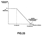
- the server terminal (mail server) 21 transmits data to mobile work machine 31 to the effect that it requests that mobile work machine 31 come to pick up the e-mail inside its mailbox. That is, a response-requested signal is sent via radio communication status channel 5 to mobile work machine 31 from the communication status satellite 9. The transmission of this response-requested signal to mobile work machine 31 from the communication status satellite 9 side is carried out continuously since often times it is not clear whether or not communication is possible, such as when mobile work machine 31 is in an environment, where communication status conditions are not good. In response thereto, confirmation of the existence of a response-requested signal is performed intermittently from the mobile work machine 31 side to the communication status satellite 9.
- Confirmation of the existence of a response-requested signal is performed by sensing a radio wave indicating that a response-requested signal has been sent from the communication status satellite 9. Therefore, a request can be reliably communicated from the communication status satellite 9 side to mobile work machine 31.
- the confirmation of the existence of this response-requested signal is performed either at the time at which a specific event occurs, or subsequent to the passage of a predetermined amount of time following the occurrence of a specific event
- the starting up of the engine of mobile work machine 31 can be detected, and this detection signal can serve as the trigger for confirming the existence of a response-requested signal.
- confirmation of the existence of a response-requested signal can be performed only when the engine is initially started up each day.
- this detection signal can serve as the trigger for confirming the existence of a response-requested signal.
- confirmation of the existence of a response-requested signal can be performed when a predetermined amount of time has passed following the carrying out of the last transmission by mobile work machine 31, and the next transmission can be performed.
- either the above-mentioned specific event or predetermined time can be arbitrarily altered. It may be constituted such that these items are changed by an input operation to an input device of terminal 11.
- mobile work machine 31 sends to the server terminal 21 via the communication status satellite 9 data to the effect that it will take delivery of the e-mail inside its mailbox. As a result thereof, e-mail is sent to mobile work machine 31 from the server terminal 21.
- the e-mail is sent to network control station 7 via the Internet 2, and the e-mail data undergoes protocol conversion. Then, the protocol-converted e-mail if sent out over a leased line 3. And then the e-mail is sent to mobile work machine 31 via the satellite earth station 8, feeder line 4, communication status satellite 9, and radio communication status channel 5, and is received by the satellite communication status antenna 58 of mobile work machine 31.
- the communication terminal 56 of mobile work machine 31 reads in the requested information identification data D3 ("vehicle location,” “fuel quantity”) from the e-mail received via the satellite communication status antenna 58, and instructs the communication status controller 54 to acquire mobile unit information corresponding to this requested information identification data D3, in other words, vehicle location data and fuel quantity data, from inside this mobile work machine 31.
- D3 vehicle location
- fuel quantity fuel quantity
- the communication status controller 54 sends vehicle location data, which is currently being detected by the GPS sensor 57, to the communication terminal 56. Further, data to the effect that "fuel quantity” should be acquired by the electronic control controller 53 is described in a frame signal and sent out over the signal wire 52.
- the electronic control controller 53 reads in the description content of the frame signal, collects detection data on the current fuel quantity from the sensor group 62 of this electronic control controller 53, and describes same in a frame signal. Then, this frame signal is sent to the communication status controller 54 via the signal wire 52.
- the communication status controller 54 reads out the fuel quantity data described in the frame signal, and sends same to the communication terminal 56. As a result of this, the communication terminal 56 incorporates the vehicle location data and fuel quantity data into a reply e-mail as mobile unit information D3'.
- Reply originator identification data D2 (mobile work machine 31) indicating the mobile unit from which the reply originated, reply destination identification data D4 (terminal 12) indicating the terminal to which the reply is sent, and mobile unit information D3' (vehicle location data and fuel quantity data) indicating the mobile unit information is sent from the communication terminal 56 via the satellite communication status antenna 58 to the communication status satellite 9 as a reply e-mail using a data structure that conforms to a prescribed communication status protocol. Furthermore, D1 and D3 are sent simultaneously. D1 can be used as a distribution key for each communication status charge billing destination. Further, D3 is used in identifying the content of D3'.
- reply originator identification data D2 (“mobile work machine 31") corresponds to the e-mail address of mobile work machine 31.
- reply destination identification data D4 (“terminal 12") corresponds to the e-mail address of the display destination terminal 12.
- the reply e-mail is received by the communication status satellite 9, and then sent to the network control station 7 via the feeder line 4, satellite earth station 8 and leased line 3.
- the data of the reply e-mail undergoes protocol conversion at this network control station 7, and the protocol-converted reply e-mail is sent out over the Internet 2.
- the server terminal 21 receives the sent e-mail, reads in the reply destination identification data D4, and stores the content of the e-mail in the mailbox of the terminal 12, which corresponds to this reply destination identification data D4 ("terminal 12").
- mobile unit information D3' (“vehicle location data,” and “fuel quantity data”) is extracted from the content of the e-mail stored in the terminal 12 mailbox, and, in addition, reply originator identification data D2 ("mobile work machine 31") is extracted, and the latest vehicle location data and fuel quantity data are stored correspondent to the address of mobile work machine 31. In this manner, the contents of the total mobile unit information are updated.
- the server terminal (mail server) 21 sends to terminal 12 data to the effect that it requests that terminal 12 come pick up the e-mail in its mailbox.
- terminal 12 sends to the server terminal 21 data to the effect that it will take delivery of the e-mail in its mailbox.
- the e-mail is sent from the server terminal 21 to terminal 12.
- the data to be sent can be limited by the security layer of D4.
- reply originator data D2 mobile work machine 31
- mobile unit information D3' vehicle location data and fuel quantity data
- the operator of transport vehicle 35 can perceive from the display screen of terminal 12 the specific type of mobile work machine 31 about which transportation instructions have been issued by the management side, and, in addition, can also perceive the current location and current fuel quantity, which are required for transporting this mobile work machine 31.
- the operator of the side of terminal 12 it is possible to obtain from the terminal 12 display screen only that information required for work without having to perform an information request input operation.
- an operator, who wants to obtain information can obtain information required for work even under conditions in which it is not possible to perform an input operation via terminal 12.
- the work of transporting mobile work machine 31 can be carried out extremely efficiently.
- the embodiment described hereinabove is constituted such that information needed for transportation is displayed on operator-side terminal 12 of the transport vehicle 35 by a request input operation performed at the management-side terminal 11, but there is also the possibility of an embodiment, such that information required for services, like maintenance and inspections, is displayed on the terminal 12 of the side of a serviceman, who is driving a service vehicle 34, by a request input operation performed at the management-side terminal 11.
- an email which treats the current location data, service meter and abnormal data of mobile work machine 31 as mobile unit information, is sent from the management-side terminal 11 to the terminal 12 of the serviceman side via the mobile work machine 31.
- reply originator data D2 mobile work machine 31
- mobile unit information D3' vehicle location data and abnormal data (error code)
- the content of the e-mail that is, the current location and current abnormal occurrence item (error code) of mobile work machine 31, are displayed on the display screen of the terminal 12.
- the serviceman driving the service vehicle 34 can perceive from the display screen of the terminal 12 the specific type of mobile work machine 31 about which service instructions have been issued by the management side, and, in addition, can also perceive the current vehicle location and current abnormal occurrence item (error code), which are required for servicing this mobile work machine 31.
- the serviceman of the side of terminal 12 it is possible to obtain from the terminal 12 display screen only that information required for work without having to perform an information request input operation, In other words, a serviceman, who wants to obtain information, can obtain information required for work even under conditions in which it is not possible to perform an input operation via terminal 12.
- the work of providing maintenance and inspection of the mobile work machine 31 can be carried out extremely efficiently.
- the terminal of the management side is server terminal 21.
- an email which treats the current oil quantity data of mobile work machine 31 as mobile unit information, is sent from serviceman-side terminal 12 to server terminal 21 via mobile work machine 31.
- reply originator data D2 mobile work machine 31
- mobile unit information D3' oil quantity data
- the manager can perceive from the display screen of server terminal 21 the specific type of mobile work machine 31 for which an oil supply service has been completed, and, in addition, can also perceive the current oil quantity, which is required for managing this mobile work machine 31.
- the manager of the side of server terminal 21 it is possible to obtain from the server terminal 21 display screen only that information required for management without having to perform an information request input operation.
- a manager who wants to obtain information, can obtain information required for managing a mobile unit even under conditions in which it is not possible to perform an input operation via the server terminal 21 side.
- the work of centrally managing mobile work machine 31-35 can be carried out extremely efficiently.
- the terminal of the request originator and the terminal of the display destination are different, but the terminal of the request originator and the terminal of the display destination can be the same.
- an email which treats the current fuel quantity and the current oil quantity data of mobile work machine 31 as mobile unit information, is sent from terminal 11 to terminal 11 via mobile work machine 31.
- reply originator data D2 mobile work machine 31
- mobile unit information D3' fuel quantity data, and oil quantity data
- the mobile work machine operator can perceive from the terminal 11 display screen the current fuel quantity and oil quantity required for a start-up inspection of the specified type of mobile work machine 31, which he is about to get into.
- the operator of the side of terminal 11 it is possible to obtain beforehand from the display screen of terminal 11 only that information necessary for a start-up inspection without having to actually go to mobile work machine 31.
- a start-up inspection of mobile work machine 31 can be performed easily and efficiently, and any inadequacies discovered via the start-up inspection can be dealt with in advance.
- the serviceman of service vehicle 34 can perceive from the display screen of terminal 11 the mobile unit information (current location, abnormal occurrences, service meter) required to service the specific type of mobile work machine 31, which he intends to service.
- the serviceman of the side of terminal 11 it is possible to obtain beforehand from the terminal 11 display screen only that information necessary for providing services without having to actually go to mobile work machine 31.
- the servicing of mobile work machine 31 can be performed easily and efficiently, and any inadequacies can be dealt with in advance.
- the serviceman can recognize an abnormal state before actually proceeding to mobile work machine 31, and can efficiently arrange for parts, call on support personnel for help and research repair methods.
- the mobile unit information extraction program is executed by the server terminal 21, and mobile unit information D3' ("vehicle location data,” “fuel quantity data”) is extracted from the content of the e-mail stored in the mailbox of the display terminal 12, and, in addition, reply originator identification data D2 ("mobile work machine 31") is extracted, and the latest vehicle location data and fuel quantity data are stored correspondent to the email address of the mobile work machine 31.
- the content of total mobile unit information MD is updated.
- the above-mentioned homepage updating program is executed on the server terminal 21, and mobile unit information of a display screen corresponding to the homepage is updated in accordance with the latest total mobile unit information MD stored in the server terminal 21.
- time sequence data such as the fuel quantity time sequence data shown in Fig. 29
- the latest data is added, and, in addition, the oldest data is deleted.
- the icon of a mobile work machine 31 on the map shown in Fig. 27 is displayed by being switched to a location on the map corresponding to the latest (current) vehicle location data.
- the display switches to the display screen shown in Fig. 28, the numerical values for "location data" and the numerical values for "fuel quantity” on the screen are displayed by being switched to the latest (current) numerical values for vehicle location data and numerical values for fuel quantity data, respectively. Further, when the display switches to the display screens shown either in Fig. 29 or Fig. 30, either a graph of changes in fuel quantity over time or an operation map are displayed by being converted to the latest one.
- the latest total mobile unit information MD related to a plurality of mobile units 31-35 updated in accordance with request input operations from a plurality of terminals 11, 12 and so forth, on the display screen of an arbitrary terminal 11.
- the latest mobile unit information for a plurality of mobile work machine 31-35 can be acquired via an arbitrary terminal, enabling the management and monitoring of all mobile units. That is, it becomes possible to centrally manage via an arbitrary terminal the latest mobile unit information related to a plurality of mobile work machine 31-35, requested by a plurality of requesters.
- databases are provided in each of server terminals 21, 22, and total mobile unit information MD is stored separately. Accordingly, by transmitting the stored data (total mobile unit information MD) of the database of the server terminal of the one side to the database of the other server terminal, it is possible to make shared use of total mobile unit information via the other server terminal database as well, and the stored content (total mobile unit information MD) of the databases of the respective server terminals can be made the same content. More specifically, this is achieved by a method, wherein e-mail (describing mobile unit information) sent back to the server terminal of the one side is automatically transmitted to the other server.
- e-mail describing mobile unit information
- a terminal 13 equivalent to terminal 11 and terminal 12 is mounted in the service vehicle 34, and the functions of the car navigation system 55 are incorporated into this terminal 13 and operated.
- E-mail which treats terminal 13 mounted in the service vehicle 34 as the display destination terminal (display destination identification data D4), and mobile work machine 31 as the request destination mobile unit (request destination identification data D2), and to which the respective data of a message stating "Failure E occurred, rush to site,” is added, is sent from the management-side terminal 11 via the same operation as was explained in Fig. 33.
- the message data stating "Failure E occurred, rush to site” is added to the e-mail by performing an input operation via a terminal 11 input device.
- the icon of a mobile work machine 31, which is the unit to be serviced is displayed in the latest (current) location on the map, and, in addition, the icon of the service vehicle 34 itself is displayed in the current location on the map. Furthermore, the current location of the vehicle 34 itself is detected by the GPS sensor 57, which is mounted in the vehicle 34 itself, and displayed on screen 13a.
- the message (“Instruction message: Failure E occurred, rush to site") sent in the e-mail is displayed.
- the serviceman riding in the service vehicle 34 can perceive from display screen 13a the fact that his next unit to be serviced (destination) is mobile work machine 31, and a message related to the current location and the job details thereof Further, an automatic route generation program is stored in terminal 13.
- this automatic route generation program when the current location of the service vehicle 34 and the destination (current location of mobile work machine 31) are provided, processing for automatically generating the shortest travel route on the map is performed. Therefore, when this automatic route generation program is executed, the shortest travel route 102 from the current location of the service vehicle 34 to the current location of mobile work machine 31, which is the destination, is displayed on display screen 13a of terminal 13.
- a click operation is performed on button 110 indicating "OK” on display screen 13a. Further, when the service vehicle 34 arrives at the destination, and work is started, a click operation is performed on button 113 indicating "Arrival” on display screen 13a. Further, when service work on mobile work machine 31 has been completed, a click operation is performed on button 112 indicating "Finished” on display screen 13a. Further, when work according to the content of the work instructions cannot be undertaken for some reason, a click operation is performed on button 111 indicating "Suspended” on display screen 13a. The content of input operations resulting from these click operations on terminal 13 is sent to the management-side terminal 11 from terminal 13 via e-mail. By receiving this e-mail at terminal 11, it is possible to comprehend the state of work progress of service vehicle 34. Furthermore, in addition to touch operations, such as click operations, key operations, and touch-panel operations, input operations can also make use of voice input operations.
- the constitution is such that e-mail, which makes terminal 13 of the service vehicle 34 the display destination terminal, is sent from the management-side terminal 11, and the content shown in Fig. 3 is displayed on terminal 13, but it is possible for the content of Fig. 3 to be displayed on terminal 13 by procedures like those hereinbelow. That is,
- the mobile unit location and the content of work instructions data indicating the job details sent from the management-side terminal 11 are arbitrary.
- the details of a job a full day's worth of job details can be specified.
- the management-side terminal 11 requesting the server terminal 21 for an operation map (Fig. 30) for service vehicle 34, it is possible to comprehend the daily rate of operation of service vehicle 34. Accordingly, by collating this daily rate of operation against a day's worth of job details directed to service vehicle 34 from the management side, it is possible to automatically and accurately prepare a daily work report.
- location of a unit to be serviced location of mobile work machine 31
- location of another service vehicle 34' can be sent as well.
- traveling to and communicating with this service vehicle 34' is made easier, and service work can be performed even more efficiently. That is, it becomes possible to borrow tools, replacement parts, and the like from the other serviceman, and it also becomes possible to request assistance. Further, if it is an experienced serviceman, it is also possible to seek his advice.
- data on the location of a single mobile work machine 31 is sent to terminal 13 of the service vehicle 34 from the management-side terminal 11, but an embodiment, which is constituted so as to send the locations of a plurality of mobile work machine 31A, 31B, 31C, 31D, and which causes a service patrol of a plurality of mobile work machine 31A-31D to be carried out efficiently, is also possible.
- the icons of the respective mobile work machine 31A-31D are displayed in their current locations on a map as shown in Fig. 5, and, in addition, the service meter increment values of the respective mobile work machine 31A-31D are displayed.
- the service meter increment values of the respective mobile work machine 31A-31D are displayed.
- an automatic patrol route generation program is stored in terminal 13.
- this automatic patrol route generation program when the current location of the service vehicle 34 itself, and a plurality of candidate sites for patrol (mobile work machine 31A-31D) are provided, processing for selecting only those patrol candidate sites having service meter increment values larger than the setting value, and for automatically generating the most efficient patrol travel route for passing through these selected patrol candidate sites is performed. Accordingly, when this automatic route generation program is executed, a patrol travel route 108, which is indicated by solid lines going from the current location of the service vehicle 34 itself to the mobile work machine 31B, 31D, which have large service meter increment values ("678H,” "500H”), and returning once again to the vehicle 34 itself, is displayed on display screen 13a of terminal 13.
- the patrol travel route 108 indicated by solid lines in Fig. 5, need not be generated automatically, but rather, can be set according to the judgment of a serviceman.
- work instructions data is sent from the management-side terminal 11 to terminal 13 mounted in the service vehicle 34, but an embodiment, which causes transport loading work to be performed efficiently by sending work instructions data from the management-side terminal 11 to terminal 14 mounted in the mobile work machine transport vehicle 35, is also possible.
- e-mail comprising the respective data of the current location of mobile work machine 31, which is at the loading site, the location of the off-loading site 106, where the loaded vehicle will be off-loaded, and a message stating "Return When Finished" is sent to terminal 14 of the mobile work machine transport vehicle 35.
- the icon of mobile work machine 31 is displayed in its current location on a map, and, in addition, the icon of off-loading site 106 is displayed in a corresponding location on the map as shown in Fig. 4. Furthermore, the current location of the transport vehicle 35 itself is detected by the GPS sensor 57 mounted in the transport vehicle 35, and displayed on screen 14a.
- the message (“Instruction message: Return when finished") sent via e-mail is displayed in the message portion 107 of the display screen of terminal 14.
- the operator riding in the transport vehicle 35 can perceive from display screen 14a the fact that the mobile work machine 31 is the next unit to be loaded, the current location thereof, the site, where this vehicle is to be off-loaded, and specific job details.
- an automatic transport route generation program is stored in terminal 14.
- processing for automatically generating the shortest transport travel route which selects only roads wide enough to enable the vehicle 35 to pass through as the route from the current location of the vehicle 35, through the loading site 31 to the off-loading site 106.
- the shortest transport travel route 104 which avoids narrow roads that are not wide enough for the vehicle 35 to pass through, and which goes from the vehicle 35 itself to mobile work machine 31 and on to off-loading site 106, is displayed on display screen 14a of terminal 14.
- a click operation is performed on button 110 indicating "OK" on display screen 14a.
- a click operation is performed on button 114 indicating "Loading" on display screen 14a.
- a click operation is performed on button 115 indicating "Off-loading” on display screen 14a.
- a click operation is performed on button 112 indicating "Finished" on display screen 14a.
- data is sent and received by utilizing an Internet 2 e-mail service.
- the server terminal 21 as the mail server, regularly checks whether or not e-mail is inside a mailbox.
- a constant delay occurs from the time e-mail is sent from a terminal (for example, terminal 11) until it is actually received by a mobile unit (for example, mobile work machine 31) of the e-mail address destination.
- the sending and receiving of data is performed via satellite radio communications by the communication status satellite 9.
- satellite radio communications when the communication status environment between the sending and receiving equipment is not good, such as when the maximum angle of elevation of the satellite is small, and an unobstructed view of a mobile unit is not achievable, a communication status channel 5 cannot be secured, thus requiring that processing, which attempts to establish communications, be carried out many times.
- a communication status environment-caused delay occurs from the time data is sent from the satellite 9 until it is actually received by a mobile unit (for example, mobile work machine 31).
- a time difference of, for example, several minutes occurs from the time e-mail is sent by a request-origination terminal until it is received by a request-destination mobile unit
- a time difference of, for example, several minutes occurs from the time e-mail is sent by a request-origination terminal until it is received by a request-destination mobile unit
- requests for mobile unit information are sent out from a plurality of terminals to a single mobile unit Consequently, it is not possible to make a judgment using a single terminal alone as to how recent the mobile unit information currently available is (when the request for mobile unit information was made).
- icons (a picture of a hydraulic excavator, a picture of a service vehicle, and a picture of a trailer, etc.) as mobile unit identifiers corresponding to a plurality of mobile units 31-35, respectively, are displayed on a terminal 11. And then, when e-mail requesting mobile unit information is sent from a request-origination terminal 11 to a request-destination mobile work machine 31, the display mode of the icon of this mobile work machine 31 changes to the modes shown in Fig. 16 (a) according to the communication status.
- Fig. 15 shows the procedures of processing for transitioning a display in accordance with communication status procedures. This processing is performed by the server terminal 21, and the results of this processing are displayed on a display screen of the terminal 11.
- Step 201 the icon of a mobile work machine 31 is displayed in the "blue" color corresponding to "No Request" (Step 201).
- Step 203 when e-mail requesting mobile unit information is sent from the request-origination terminal 11 to the request-destination mobile work machine 31, and this e-mail is stored in the mailbox of the mobile work machine 31 (YES decision in Step 202), the icon of the mobile work machine 31 transitions to the "yellow” color display corresponding to "Request in Progress" (Step 203).
- Step 207 when e-mail returned from the request-destination mobile work machine 31 is stored in a mailbox (YES decision in Step 204), the icon of the mobile work machine 31 transitions to the "green" color display corresponding to "Reply” (Step 207).
- Step 208 When one day has elapsed from the transition to the "Reply” state (YES decision in Step 208), the icon of the mobile work machine 31 returns to the "blue” color display corresponding to "No Request” (Step 201).
- the returned mobile unit information is sent to and displayed on a display-destination terminal (for example, terminal 12), it may be constituted such that the process moves from Step 207 to Step 201 to return to the "blue" color display corresponding to "No Request"
- Step 206 when e-mail, which should have been returned from the request-destination mobile work machine 31 is not stored in a mailbox (NO decision in Step 204, YES decision in Step 205), a determination is made that it will be difficult to ensure a radio communication status channel 5, and the icon of the mobile work machine 31 transitions to the "red" color display corresponding to "No Reply" (Step 206).
- the display mode changes in accordance with the communication status, and the "degree of communication status delay" can be perceived on the display screen of terminal 11. Also, making requests that duplicate those of other terminals is eliminated. Thus, reduced work efficiency and increased communication status costs brought on by unknown communication status can be avoided.
- Step 301 when e-mail requesting mobile unit information is sent from terminals 11, 12, and so forth to the request-destination mobile work machine 31, and this e-mail is stored in the mailbox of mobile work machine 31 (Yes decision in Step 301), a timer is reset (Step 305), and the icon of the mobile work machine 31 transitions to the "blue" color display corresponding to "No Request #0" (Step 306).
- Step 306 when the elapsed time following the resetting of the timer is less than one day (NO decision in Step 302), the icon of the mobile work machine 31 retains the "blue" color display corresponding to "No Request #0" (Step 306).
- Step 307 when the elapsed time following the resetting of the timer is longer than one day but less than three days (YES decision in Step 302, NO decision in Step 303), the icon of the mobile work machine 31 transitions to the "yellow" color display corresponding to "No Request #1" (Step 307).
- Step 308 when the elapsed time following the resetting of the timer is longer than three days but less than one week (YES decision in Step 303, NO decision in Step 304), the icon of the mobile work machine 31 transitions to the "pink" color display corresponding to "No Request #2" (Step 308).
- the icon of the mobile work machine 31 retains the "red” color display corresponding to "No Request #3" (Step 309).
- Step 301 When e-mail requesting mobile unit information is sent from terminals 11, 12, and so forth to request-destination mobile work machine 31 while the timer is clocking time, and this e-mail is stored in the mailbox of mobile work machine 31 (Yes decision in Step 301), the timer is reset (Step 305), and the icon of a mobile work machine 31 transitions to the "blue" color display corresponding to "No Request #0" (Step 306).
- the elapsed time from a final request to mobile work machine 31 is displayed on terminal 11, but this elapsed time is similarly displayed for other mobile units 32-35 as well. Further, the elapsed time from a final request to the respective mobile work machine 31, 32, 33, 34, 35 is also displayed on other terminals, such as terminal 12 and so forth.
- the state of elapsed time from the last request to the respective mobile units 31-35 can be perceived on the display screen of a terminal, and management-related information, such as how recent the mobile unit information currently available for mobile units 31-35 is, can be learned.
- Incoming Message comprises both a case in which e-mail indicating mobile unit information from a mobile unit is returned, and, as will be explained below, a case in which e-mail indicating mobile unit information from a mobile unit is automatically transmitted without a request from the terminal side.
- Step 405 when a reply from the mobile work machine 31 or e-mail automatically transmitted by the mobile work machine 31 is stored in the mailbox of the server terminal 21 (YES decision in Step 401), a timer is reset (Step 405), and the icon of the mobile work machine 31 transitions to the "blue" color display corresponding to "No Incoming Message #0" (Step 406).
- Step 406 the icon of the mobile work machine 31 retains the "blue" color display corresponding to "No Incoming Message #0" (Step 406).
- Step 407 when more than one day but less than three days has elapsed from the time the timer was reset (YES decision in Step 402, NO decision in Step 403), the icon of the mobile work machine 31 transitions to the "yellow" color display corresponding to "No Incoming Message #1" (Step 407).
- Step 403 when more than three days but less than one week has elapsed from the time the timer was reset (YES decision in Step 403, NO decision in Step 404), the icon of the mobile work machine 31 transitions to the "pink" color display corresponding to "No Incoming Message #2" (Step 408).
- Step 404 when more than one week has elapsed from the time the timer was reset (YES decision in Step 404), the icon of the mobile work machine 31 transitions to the "red” color display corresponding to "No Incoming Message #3" (Step 409).
- Step 401 When a reply from the mobile work machine 31 or e-mail automatically transmitted by the mobile work machine 31 is stored in the mailbox of the server terminal 21 while the timer is clocking time (YES decision in Step 401), the timer is reset (Step 405), and the icon of the mobile work machine 31 transitions to the "blue" color display corresponding to "No Incoming Message #0" (Step 406).
- the elapsed time from a final incoming message from mobile work machine 31 is displayed, but this elapsed time is similarly displayed for other mobile units 32-35 as well. Further, the elapsed time from the last incoming message from the respective mobile work machine 31, 32, 33, 34, 35 is also displayed on other terminals, such as terminal 12 and so forth.
- the state of elapsed time from a last incoming message from the respective mobile units 31-35 can be perceived on the display screen of a terminal, and management-related information, such as how recent the mobile unit information currently available for mobile units 31-35 is, can be learned. Further, when a mobile unit (for example, mobile unit 31) is automatically transmitting at regular periods, from the content of the display of elapsed time from the last incoming message from mobile unit 31, it is possible to discern at the terminal side whether or not a communication status malfunction of some sort occurred when mobile unit 31 made an automatic transmission.
- a mobile unit for example, mobile unit 31
- Step 501 when e-mail requesting mobile unit information is sent to request-destination mobile work machine 31 from request-origination terminal 11, and e-mail returning from request-destination mobile work machine 31 as a reply thereto is stored in a mailbox (YES decision is Step 501), the icon of the mobile work machine 31 transitions to the "blue" color corresponding to "No Request” (Step 506).
- Step 501 the process moves to the next Step 502.
- Step 502 a determination is made as to whether or not e-mail requesting mobile unit information was sent from request-origination terminal 11 to request-destination mobile work machine 31 and stored in the mailbox of mobile work machine 31, in other words, whether or not there was a request (Step 502).
- Step 502 When there was a request (YES decision in Step 502), a timer is reset, and when the elapsed time following the timer being reset is less than one minute (NO decision in Step 503), the icon of the mobile work machine 31 transitions to the "green" color display corresponding to "No Reply #0" (Step 507).
- Step 508 when the elapsed time following the timer being reset is more than one minute but less than three minutes (YES decision in Step 503, NO decision in Step 504), the icon of the mobile work machine 31 transitions to the "yellow" color display corresponding to "No Reply #1" (Step 508).
- Step 505 when the elapsed time following the timer being reset is more than three minutes but less than ten minutes (YES decision in Step 504, NO decision in Step 505), the icon of the mobile work machine 31 transitions to the "pink" color display corresponding to "No Reply #2" (Step 509).
- Step 505 when the elapsed time following the timer being reset is more than ten minutes (YES decision in Step 505), the icon of the mobile work machine 31 transitions to the "red” color display corresponding to "No Reply #3" (Step 510).
- Step 501 When e-mail returned from request-destination mobile work machine 31 is stored in a mailbox while the timer is clocking time (YES decision in Step 501), the icon of the mobile work machine 31 transitions to the "blue" color corresponding to "No Request” (Step 506).
- the elapsed time following the sending of a request to a mobile unit until a reply is received is displayed, it can readily be determined from a display screen on a terminal whether or not communications are being performed normally.
- the color of the entire icon of this mobile work machine 31 is changed and displayed as shown in Fig. 16(a), but the icon colors can be changed to color combinations, color arrangements, or shaded patterns. Further, a component other than color can be changed.
- the shape of the icon of this mobile work machine 31 can be changed and displayed as shown in Fig. 16 (b). For example, if it is an icon of a hydraulic excavator, the position or the rounded portion of the work machinery can be changed.
- the size of the icon of this mobile work machine 31 can be changed and displayed as shown in Fig. 16 (c).
- the size of the hydraulic excavator icon intermittently changes from large to medium and from medium to large.
- the movement of the icon of this mobile work machine 31 can be changed and displayed as shown in Fig. 16 (d).
- Fig. 16 (d) For example, in the case of "No Request” shown in Fig. 16 (c), the hydraulic excavator icon is still, in the case of "Request in Progress," the hydraulic excavator icon is rotating, in the case of "Reply,” the hydraulic excavator icon moves linearly, and in the case of "No Reply,” the hydraulic excavator icon jumps.
- the icon of this mobile work machine 31 can be changed and displayed as a flashing pattern. For example, changing the flash cycle is being considered.
- this embodiment can be constituted such that characters or other such identification symbols identifying a mobile work machine 31 change. For example, changing the color or flashing the characters indicating the vehicle number or nickname of a mobile work machine 31 is being considered.
- the icons of a plurality of mobile work machine 31, 32, 33, 36, 37, 38 are displayed correspondent to mobile unit information ("vehicle number,” “location,” “service meter”) in a display screen of a terminal 11 as shown in Fig. 17 (a).
- the icons of the respective mobile work machine 31, 32, 33, 36, 37, 38 can be displayed on a screen in a preset order.
- the icons of the respective mobile work machine 31, 32, 33, 36, 37, 38 can also be rearranged in accordance with the communication status, displaying the icons of mobile work machine 31, 32 corresponding to "Request in Progress" in the top positions, and displaying the icons of mobile work machine 33, 36, 37 corresponding to "No Request" in the bottom positions.
- the content of a terminal display changes in accordance with changes in communication status, it is possible to prevent decreases in work efficiency resulting from unknown communication status, and it is also possible to prevent increases in communication status costs. Further, it is possible to obtain management information (whether or not maintenance and inspections have been performed recently), such as how recent the mobile unit information of the respective mobile unit is, from a display screen.
- This embodiment wherein the content of a terminal display changes in accordance with changes in communication status, is not limited to the communication device shown in Fig. 1, and can be applied to an arbitrary communication device. If a communication device comprises at a minimum two communication status stations, and performs communications between two communication status stations, then this embodiment is applicable.
- the time period during which the engine is not running (that is, the time period during which it is operating with the power OFF) is long.
- a communication terminal 56 is constantly electrically connected to a battery 63 (rated voltage 24V) even while the engine is OFF, since the engine is not running, the battery 63 is not charged by an alternator. Thus, battery 63 discharge will occur rapidly.
- the electrical connection between the battery 63 and the communication terminal 56 is constantly OFF while the engine is OFF, communications with a plurality of terminals 11, 12 and so forth, will become impossible.
- the engine is OFF, it is not possible to reply to this request.
- the embodiment described hereinbelow is constituted so as to make it possible to communicate with a plurality of terminals 11, 12 and so forth while an engine is OFF, to enable a reply to be given to a request from a terminal 11, 12 and so forth, and, in addition, to enable wasteful power consumption to be held in check even for construction machine and other such mobile units 31-35 for which engine non-running time is long.
- Fig. 21 shows the constitution of this embodiment
- a communication terminal 56 is provided onboard a mobile work machine 31. And the power terminal ofthis communication terminal 56 is electrically connected to a battery 63.
- a main power circuit is disposed inside the communication terminal 56, and power is consumed by the power of the battery 63 being supplied to this main power circuit.
- the level of an engine key switch signal S1 inputted to a sleep control terminal of the communication terminal 56 is monitored by software, and when it is an ON signal, and the main power circuit of the communication terminal 56 is OFF, processing for forcibly driving the main power circuit is performed. Further, it may be constituted such that the main power circuit is driven by hardware.
- the power terminal of the communication status controller 54 is electrically connected to the battery 63 via the engine key switch 64.
- the engine key switch 64 being turned OFF, the electrical connection between the communication status controller 54 and the battery 63 is cut off, and, in addition, the operation of the engine of the mobile work machine 31 is stopped.
- an ON signal (logical "1" level signal) of an engine key switch signal S1 is outputted to the sleep control terminal of the communication terminal 56 from the communication status controller 54.
- Fig. 7 (a) shows an operating signal S1 of the engine key switch 64
- Fig. 7 (b) shows the communication status between the communication terminal 56 and the communication status satellite 9. Communications in progress is indicated by the logical "1" level.
- Fig. 7 (c) shows the activation status of the communication terminal 56.
- the logical "1" level corresponds to the activation state (power-saving operation OFF)
- the logical "0" level corresponds to the activation OFF (sleep) state (power-saving operation ON).
- signals indicating mobile unit information such as current location, service meter values, remaining fuel, battery voltage, and vehicle error codes, are sent to the communication status satellite 9 from the communication terminal 56 as needed.
- Fig. 8 (b) is a timing chart showing the ON, OFF of a power-saving operation corresponding to Fig. 7 (c), and Fig. 8 (c) shows the transmission state of a call request signal to the communication terminal 56 from the communication status satellite 9.
- the logical "1" level indicates a transmission in progress.
- a time ⁇ when the communication terminal 56 is inevitably active in other words, a time when it is possible to send to and receive from the communication status satellite 9, exists within a fixed time (activation period) T (Refer to the slashes in Fig. 8 (c).).
- the expected value of communication reply time is T/2 (the average is T/2). Further, power consumption can be held down to ⁇ /T.
- the activation period T is determined in accordance with the criticality of the communications, and the safety factor relative to the duration of the signal sent out from the communication status satellite 9.
- the active time ⁇ it is necessary to ensure a time period longer than that required for sending and receiving procedures.
- the shorter the active time ⁇ the greater the power-saving effect
- the sleep function is forcibly terminated when the engine is operated, and the communication terminal 56 is constantly active during engine operation, mobile unit information, such as a sudden vehicle abnormality that occurs during engine operation, can be transmitted, and safety can be ensured. Further, if communications are in progress, because the communication terminal 56 remains active as-is until the end of communications even when engine operation is stopped, communications can be performed with certainty.
- the above-mentioned duty ratio D can be changed to conform to the terminal voltage of the battery 63.
- the voltage of the battery 63 is inputted to a battery voltage input circuit, and duty ratio D changes in accordance with the characteristics shown in Fig. 8 (a).
- a power-saving operation control function at engine key switch 64 ON can be provided in equipment other than the communication terminal 56, for example, in the communication status controller 54, and the ON, OFF of the electrical connection between the communication terminal 56 and the battery 63 can by intermittently controlled by this communication status controller 54.
- the power terminal of the communication terminal 56 is electrically connected to the battery 63 via a power switch 65.
- the electrical connection between the communication terminal 56 and the battery 63 is cut off in accordance with the power switch being turned OFF.
- the power terminal of the communication status controller 54 is electrically connected to the battery 63. Further, the operating signal S1 of engine key switch 64 is inputted into the communication controller 54. Further, a signal S3 indicating the communication status is inputted from the communication terminal 56 to the communication controller 54. When the communication terminal 56 is in the process of communicating with the communication satellite 9, the communication status signal S3 becomes a logical "1" level.
- the communication controller 54 executes the same processing as was explained using Fig. 7.
- Fig. 7 (a) shows the operating signal S1 of the engine key switch 64, which is inputted to the communication controller 54
- Fig. 7 (b) shows the communication status signal S3, which is inputted from the communication terminal 56 to the communication controller 54
- Fig. 7 (c) shows the power switch drive signal S2, which is outputted from the communication controller 54 to the power switch 65.
- duty ratio D can similarly be changed in conformance to the battery 63 terminal voltage or engine operation time.
- the above-mentioned duty ratio D can be changed in accordance with the location information of a mobile work machine 31.
- Fig. 23 shows an embodiment for changing the duty ratio D for mobile work machine 31 in accordance with a relative travel distance in relation to a set range.
- Fig. 23 (a) shows a situation in which the activation period T is shortened and the duty ratio D is increased in conformance to mobile work machine 31 departing from a set range 117 on a map.
- a predetermined range 117 within which mobile work machine 31 is normally expected to be, is set on a map of a display screen of a terminal 11.
- this set range 117 is a management area for which a manager on the terminal 11 side is responsible, or an administratively approved work area.
- the location of the mobile work machine 31 is detected by the GPS sensor 57 as shown in Fig. 2.
- the GPS measurement devices GPS antenna 59, GPS sensor 57, communication controller 54
- these GPS measurement devices can be electrically connected directly to the battery 63 and operated at all times.
- the above-described sleep function can be turned ON, a power-saving operation can be turned ON and OFF, and the GPS measurement devices can be operated and measure a location only when a power-savings operation is ON (when the communication terminal 56 is active).
- the location detected by the GPS sensor 57 for the mobile work machine 31, and the boundary location of the set range 117 are compared, and processing for changing the activation period T is executed in accordance with the results of this comparison.
- Fig. 23 (d) shows a situation in which the activation period T is changed in accordance with a relative location (passage of time) in relation to the set range 117 of the mobile work machine 31.
- the activation period T constitutes the maximum period T1.
- the activation period T becomes a period T2, which is shorter than the maximum period T1 (Refer to Fig. 23 (d)).
- the activation period T can be made consecutively shorter.
- the response to a request from a terminal 11 becomes faster. Furthermore, as will be explained hereinbelow, when the mobile work machine 31 is transmitting automatically, the transmission interval of mobile unit information, such as location information, becomes shorter.
- a more detailed travel locus (a travel locus, the time interval between each displayed travel location of which is short) is displayed on a display screen of the terminal 11, which is the display-destination terminal.
- an abnormal situation such as mobile work machine 31 traveling outside of an authorized area.
- the ON, OFF duty ratio D of the activation of the communication terminal 56 increases in accordance with the mobile work machine 31 moving away from the normal set range 117, it is possible to hold down power consumption in line with communications, while at the same time accurately monitoring the abnormal situation.
- Fig. 23 (b) shows a situation in which the activation period T becomes shorter and the duty ratio D becomes larger in conformance to mobile work machine 31 entering a set range 118 on a map.
- a predetermined range 118 within which mobile work machine 31 would not normally be brought, is set on a map of a display screen of a terminal 11.
- This set range 118 is an abnormal area, for example, an area in which it is against the law to work, such as a foreign harbor, a hazardous work area, a nature conservation area, or the like.
- Fig. 23 (d) shows a situation in which the activation period T is changed in accordance with a relative location (passage of time) in relation to the set range 118 of the mobile work machine 31.
- the activation period T constitutes the maximum period T1.
- the activation period T becomes a period T2, which is shorter than the maximum period T1 (Refer to Fig. 23 (d)).
- the activation period T can be made consecutively shorter.
- a more detailed travel locus (a travel locus, the time interval between each displayed travel location of which is short) is displayed on a display screen of the terminal 11, which is the display-destination terminal.
- an abnormal situation such as a mobile work machine 31 entering a hazardous area.
- the ON, OFF duty ratio D of the activation of the communication terminal 56 increases in accordance with the penetration of the mobile work machine 31 into the abnormal set range 118, it is possible to hold down power consumption in line with communications, while at the same time accurately monitoring the abnormal situation.
- this embodiment is not limited to monitoring the abnormal situations hypothesized by Fig. 23 (a), (b), but rather can also be used to monitor the route to the location where mobile work machine 31 is discarded and disposed of.
- the embodiment shown in Figs, 23 (a) and 23 (b) is constituted such that the activation period T is univocally determined from only the distance L to a boundary line of a set range 117, 118, but the activation period T can also be determined by also taking factors other than distance L into consideration, such as orientation, surrounding geographical information, type of mobile unit, and mobile unit utilization period.
- duty ratio D can also be changed in accordance with the extent of the change of location of mobile work machine 31 as shown in Fig. 24.
- the location of the mobile work machine 31 is detected by the GPS sensor 57 as shown in Fig. 2.
- the GPS measurement devices GPS antenna 59, GPS sensor 57, communication controller 54
- these GPS measurement devices can be electrically connected directly to the battery 63 and operated at all times.
- the above-described sleep function can be turned ON, a power-saving operation can be turned ON and OFF, and the GPS measurement devices can be operated and measure a location only when a power-savings operation is ON (when the communication terminal 56 is active).
- Fig. 24 (b) shows a situation in which the activation period T changes in accordance to whether or not a mobile work machine 31 has moved outside of circles 119, 120 and so forth.
- a circle 119 of a radius S(km), which has location A at the center is set on a map.
- the initial activation period T is set at the maximum period T1.
- the communication terminal 56 is started up after the period T1. It is supposed that the location detected by the GPS sensor 57 at that time was location B of the inside of circle 119. In this case, the activation period T is left at the maximum period T1 as-is.
- the communication terminal 56 is activated, and it is supposed that the location detected by the GPS sensor 57 at that time was location C of the outside of circle 119.
- a circle 120 of a radius S(km), which has location C at the center is set on the map, and, in addition, the activation period T is changed to a period T2, which is shorter than the maximum period T1.
- the communication terminal 56 is activated. It is supposed that the location detected by the GPS sensor 57 at that time was location D of the inside of circle 120. In this case, the activation period T is left at the period T2 as-is. After another period T2, the communication terminal 56 is activated, and it is supposed that the location detected by the GPS sensor 57 at that time was location E of the outside of circle 120. In this case, a circle 121 of a radius S(km), which has location E at the center, is set on the map, and, in addition, the activation period T is changed to a period T3, which is shorter than the period T2.
- the communication terminal 56 is activated, and it is supposed that the location detected by the GPS sensor 57 at that time was location F of outside of circle 121.
- a circle 122 of a radius S(km), which has location F at the center, is set on the map, and, in addition, the activation period T is changed to a period T4, which is shorter than the period T3.
- the communication terminal 56 is activated. It is supposed that the location detected by the GPS sensor 57 at that time was location G of the inside of circle 122. In this case, the activation period T is returned from the period T4 to the period T3, which is longer (Refer to Fig. 24 (b)).
- an embodiment which treats areas 119, 120 and so forth shown in Fig. 23 (a) as a shape other than a circle or square is also possible.
- an elliptic or rectangular area which is elongated in either of the two directions of latitude or longitude, can also be used.
- the area may take an elliptic or rectangular shape extending in the direction in which the mobile work machine 31 travels. In this case, a determination as to whether or not the mobile work machine 31 has gone outside an area can be made more rapidly and more accurately.
- the size of the areas 119, 120 and so forth, more specifically, the value of the radius S(km) if the areas are circles, can be changed in accordance with the amount of movement.
- the activation period T becomes shorter, and a more detailed travel locus (a travel locus, the time interval between each displayed travel location of which is short) is displayed on a display screen of the terminal 11, which is the display-destination terminal, equivalently in accordance with the travel velocity of mobile work machine 31 increasing.
- a travel locus the time interval between each displayed travel location of which is short
- Figs. 24 (a) and 24 (b) The embodiment shown in Figs. 24 (a) and 24 (b) is constituted such that the activation period T is changed in accordance with whether or not the mobile work machine 31 has gone beyond areas 119, 120 and so forth, which are set up sequentially, but as shown in the graph of Fig. 25, the travel velocity V of the mobile work machine 31 can be computed for each activation period T, and the activation period T can be changed in accordance with the size of the computed velocity V thereof.
- V (location detected at this activation - location detected at last activation) /current activation period T
- the relationship between the travel velocity V and the activation period T is shown in the graph of Fig. 25.
- the activation period T becomes shorter.
- the activation period T becomes 0 (duty ratio D is 1), that is, the communication terminal 56 is in a continuously active state.
- the activation period T is determined by finding the activation period T corresponding to the travel velocity V determined by the above operational expression from the graph shown in Fig. 25.
- the activation period T becomes shorter, and a more detailed travel locus (a travel locus, the time interval between each displayed travel location of which is short) is displayed on a display screen of the terminal 11, which is the display-destination terminal. For this reason, it is possible to accurately comprehend on the terminal 11 side a condition, in which work has been completed at one work site, and the mobile work machine 31 is moving to the next work site.
- the activation of the communication terminal 56 is performed intermittently at predetermined periods T, but the activation of the communication terminal 56 can also be performed intermittently each time it becomes a specified time.
- an embodiment which activates the communication terminal 56 when it is a specified time at which communications between the communication satellite 9 and mobile work machine 31 can be carried out satisfactorily, is also possible.
- This specified time corresponds to the location (altitude) of the communication satellite 9.
- Fig. 13 (a) shows the physical relationship of the communication satellite 9 and the mobile work machine 31.
- the flight position data of the communication satellite 9 changes daily. Thus, if an attempt is made to store flight position data for all dates in mobile work machine 31 memory, this will give rise to insufficient memory capacity and memory occupation problems.
- a predetermined quantity of flight position data 124 is sent via a radio communication channel 5 to the mobile work machine 31 from the communication satellite 9 as shown in Fig. 13 (a).
- a clock is provided on the inside of the communication terminal 56 of the mobile work machine 31. Consequently, by collating the received flight position data 124 against the time clocked by the clock, a determination is made as to whether or not to activate the communication terminal 56.
- Fig. 13 (b) shows the flight position data of the communication satellite 9 for a certain date.
- FIG. 13 (b) "AOS” indicates the time and azimuth angle at which the communication satellite 9 appears on the horizon, "MEL” indicates the time and azimuth angle when the communication satellite is at the maximum angle of elevation, and "LOS” indicates the time and azimuth angle at which the communication satellite 9 disappears over the horizon.
- the path of the communication satellite 9, which corresponds to an enclosed portion, is shown in Fig. 13 (c).
- processing which activates the communication terminal 56 at a time when a maximum angle of elevation of greater than a predetermined threshold value (for example, 45 degrees) is obtained from the flight position data 124 shown in Fig. 13 (b), in other words, at the times 4:33, 16:28 at which maximum angles of elevation 66°, 54° are obtained, is executed. That is, when it becomes the specified times 4:33, 16:28, the main power circuit of the communication terminal 56 is driven, and a signal designating mobile unit . information is sent to the communication satellite 9 via a radio communication channel 5.
- a predetermined threshold value for example, 45 degrees
- flight position data 124 for example, new data is sent from the communication satellite 9 to the mobile work machine 31 via the radio communication channel 5 every day at the above specified times.
- the content of the flight position data 124 stored in the memory of the mobile work machine 31 is updated.
- the communication terminal 56 is activated whenever it becomes a specified time at which communications between the communication satellite 9 and the mobile work machine 31 can be performed satisfactorily, power savings can be achieved, and, in addition, communications between the communication satellite 9 and the mobile work machine 31 can be carried out with certainty. Further, since the flight position data 124 is received from the outside via communications, insufficient memory capacity and memory occupation problems are not incurred.
- activation of the communication terminal 56 is performed intermittently at predetermined periods T, but, for example, an embodiment, in which this activation period T is arbitrarily changed from the management-side terminal 11, is also possible.
- e-mail describing change-data to the effect that the activation period T is to be changed is sent from terminal 11 to mobile work machine 31 having this mobile work machine 31 as the e-mail address.
- the change-data described in the e-mail is read out in the communication terminal 56 of the transmission-destination mobile work machine 31, and the activation period T is changed in accordance with the content of this change-data.
- the activation period T is shortened to diligently perform status monitoring at short intervals, and when the mobile work machine 31 is rented to a certain user (when there is no need for monitoring), or when it is resting for a long time (when it is clear that operation has stopped), the activation period T is lengthened to increase the monitor interval, and to reduce wasteful power consumption and communication channel charges. Furthermore, it is also possible to simultaneously change to the same activation period T for a plurality of mobile units, which are working and traveling as a group.
- the embodiment for intermittently turning ON this communication channel power source is not limited to the communication device shown in Fig. 1, and can be applied to an arbitrary communication device. This embodiment is applicable so long as a communication device comprises at the least two communication channel stations, and communications are performed between two communication stations.
- the embodiment described hereinbelow is constituted such that, if a parameter on the inside of a mobile unit is a specified value, specified mobile unit information is automatically transmitted, and this specified mobile unit information is displayed on a terminal even under conditions in which there is no request from the terminal side.
- an abnormal condition for example, a malfunction
- a mobile unit which cannot be constantly managed and monitored by the terminal side
- an internal parameter of mobile work machine 31 for example, the start state of the engine, is detected by a predetermined sensor from among a group of sensors 62 (for example, the sensor for detecting an alternator voltage value) as shown in Fig. 2.
- This sensor detection signal is inputted to the communication terminal 56 via the communication controller 54 by being described in a frame signal and sent out over the signal wire 52 by the electronic control controller 53.
- a well-known technology other than this method can also be utilized.
- Fig. 26 (a) shows a signal designating the start state of an engine, which is inputted into the communication terminal 56 of the mobile work machine 31.
- Fig. 26 (a) shows the engine start state of each time t of the day (from 6:00AM until the 6:00AM the next day), a logical "1" level corresponds to a state in which the engine is running (started), and a logical "0" level corresponds to a state in which engine operation is stopped.
- An automatic transmission from the mobile work machine 31, for example, can be performed at the timing of each engine start as shown in Fig. 26 (b).
- server terminal 21 is a management-side terminal
- the sequential locations of each time the engine is started by the mobile work machine 31 are displayed on a display screen of the management-side terminal 21. Accordingly, it is possible for a manager to grasp the history of locations of each time the engine is started by a mobile work machine 31 on the display screen without having to carry out a request input operation on his own, it is possible to perceive an abnormal situation, which occurs to the mobile work machine 31, which is incapable of being managed and monitored at all times, and it is possible to accurately comprehend an operating state and a resting state of the mobile work machine 31.
- e-mail can also be sent from the mobile work machine 31 having another terminal 11, terminal 12, and so forth as the e-mail address.
- an automatic transmission from the mobile work machine 31 can also be performed at the timing of the initial engine start of the day as shown in Fig. 26 (c).
- a start signal indicating that the engine is started is inputted into the communication terminal 56.
- a clock is provided on the inside of the communication terminal 56, and a determination is made as to whether or not this start signal is the signal initially inputted during the day (from 6:00 until 6:00 the next day). Only when the inputted start signal is determined to be the initially inputted start signal is this start signal treated as a trigger, and, as indicated by arrow f, the current location of the mobile work machine 31 is incorporated into e-mail, and sent to the communication satellite 9 as e-mail. Accordingly, a history of locations of the mobile work machine 31 is similarly displayed on a management-side terminal. According to this embodiment, since the automatic transmission interval is at the least one day, communication charges can be held down compared to the case of Fig. 26 (b).
- this embodiment is constituted such that an automatic transmission is performed only when the engine is initially started for the day, but the period can be set arbitrarily, and, for example, can also be set such that automatic transmission is performed only when the engine is initially started for the week.
- this embodiment may be constituted such that an automatic transmission from the mobile work machine 31 is performed at engine starting time at a specified time period during the day (for example, for the time period 18:00 to 6:00) as shown in Fig. 26 (d).
- a signal indicating the engine is started is inputted to the communication terminal 56
- this signal serves as a trigger
- the current location of the mobile work machine 31 is incorporated into e-mail, and is sent to the communication satellite 9 as e-mail.
- a history of locations at a specified time period of the mobile work machine 31 is similarly displayed on a management-side terminal.
- the specified time period (night-time) of 18:00 to 6:00 is a time period during which construction machine and other such mobile work machine are normally not operated. It is also a time period during which long-term movement is not carried out.
- this embodiment may also be constituted such that an automatic transmission from the mobile work machine 31 is performed at the timing at which the engine stops due to an abnormality as shown in Fig. 26 (e).
- an abnormality which has occurred in the mobile work machine 31, for example, an abnormality such as "high engine speed,” “high engine exhaust temperature,” “high cooling water temperature,” “low battery voltage,” or “low fuel quantity” is detected by a predetermined sensor among a group of sensors 62.
- This sensor detection signal is inputted to the communication terminal 56 via the communication controller 54 by being described as an error code (for example, "Abnormal item: low fuel quantity") in a frame signal and sent out over the signal wire 52 by the electronic control controller 53.
- an error code for example, "Abnormal item: low fuel quantity
- a stop signal indicating that the engine is stopped is inputted into the communication terminal 56.
- the above-mentioned error code is inputted into the communication terminal 56.
- this stop signal serves as a trigger, and, as indicated by arrow g, the current location of the mobile work machine 31 is incorporated into e-mail, and is sent to the communication satellite 9 as e-mail.
- the location of the mobile work machine 31 is similarly displayed on a management-side terminal. According to this embodiment, since the location of a mobile work machine 31 is displayed on the terminal side only when an abnormality is detected and the engine is stopped, the location of the mobile work machine 31 at the time the abnormality occurred can be accurately grasped. Accordingly, the abnormality can be dealt with quickly, and the damage to the mobile work machine 31 can be held to the minimum.
- an automatic transmission is not simply carried out when an abnormality occurs, but rather, this embodiment can also be constituted such that specific abnormality items (serious abnormality items) are set in advance among the abnormality items (error codes), and an automatic transmission is performed only when these serious abnormalities occur.
- this embodiment can also be constituted such that an automatic transmission from the mobile work machine 31 is performed at the timing of engine start resulting from the annulment of an abnormality as shown in Fig. 26 (f).
- a start signal indicating that the engine has started is inputted to the communication terminal 56.
- the above-mentioned error code is inputted into the communication terminal 56.
- the error code is not longer inputted into the communication terminal 56.
- a determination is made as to whether or not the engine started when the error code ceased to be inputted into the communication terminal 56.
- this start signal serves as a trigger, and, as indicated by arrow h, the current location of the mobile work machine 31 is incorporated into e-mail, and sent to the communication satellite 9 as e-mail. Accordingly, the location of the mobile work machine 31 is similarly displayed on a management-side terminal. According to this embodiment, since the location of the mobile work machine 31 is displayed on the terminal side only when an abnormality is annulled and the engine is started, it is possible to accurately grasp the location of the mobile work machine 31 when an abnormality was properly dealt with.
- this embodiment can also be constituted such that specified mobile unit information, for example, the operation map (record showing engine operation from a certain hour and minute to a certain hour and minute) up until 23:00 of this day, is automatically transmitted from mobile work machine 31 at a specified time (for example, at 23:00).
- specified mobile unit information for example, the operation map (record showing engine operation from a certain hour and minute to a certain hour and minute) up until 23:00 of this day, is automatically transmitted from mobile work machine 31 at a specified time (for example, at 23:00).
- a specified time for example, at 23:00
- this embodiment can also be constituted such that specified mobile unit information is automatically transmitted from mobile work machine 31 at a specified time every few days (for example, at 23:00 every third day).
- this embodiment can also be constituted such that specified mobile unit information is automatically transmitted from mobile work machine 31 at a specified time each specified day of the week (for example, at 23:00 every Saturday).
- specified mobile unit information of mobile work machine 31 can be acquired regularly from a display screen of the terminal side.
- the cumulative value of the operating time of mobile work machine 31 constitutes a specified operating-time cumulative value
- specified mobile unit information for example, "service meter,” “vehicle warning 1 (error code 1),” “vehicle warning 2 (error code 2),” “battery voltage,” “engine water temperature,” “engine speed,” “pump pressure” or “oil quantity”
- service meter can be automatically transmitted.
- specified mobile unit information is sent when the cumulative operating time constitutes a specified operating-time cumulative value, preliminary information for carrying out regular inspections authorized by law can be acquired via a display screen of the terminal side. Further, since this specified operating-time cumulative value is automatically transmitted in accordance with the progress of operating time (load), wasteful communications can be avoided during rest periods, and communication costs can be held in check.
- each time the cumulative value of the operating time of the mobile work machine 31 increases by a specified amount for example, each time the incremental value of the service meter increases by 100 hours from the last automatic transmission (or each time 500 hours elapses), specified mobile unit information (for example, “service meter,” “vehicle warning 1 (error code 1),” “vehicle warning 2 (error code 2),” “battery voltage,” “engine water temperature,” “engine speed,” “pump pressure” or “oil quantity" can be automatically transmitted.
- setting the incremental value of the service meter can be done by matching it up with the patrol time of a service vehicle 34.
- the above-mentioned automatic transmission may be performed when the location of mobile work machine 31 changes.
- the location of mobile work machine 31 is detected by the GPS sensor 57 as shown in Fig. 2.
- the detection results of the GPS sensor 57 are inputted into the communication controller 54.
- post-change location information is sent to the communication terminal 56 as transmission data.
- e-mail in which the location information is described, is automatically transmitted from the communication terminal 56 via the satellite communication antenna 58.
- the movement history of the mobile work machine 31 can be acquired via a display screen of the terminal side.
- this embodiment can also be constituted such that an automatic transmission is performed when mobile work machine 31 departs from a specified set range 129 as shown in Fig. 10.
- the location of the mobile work machine 31 is detected by the GPS sensor 57 as shown in Fig. 2.
- the detection results of the GPS sensor 57 are inputted into the communication controller 54.
- Work site location information is stored in the communication controller 54.
- This set range 129 of the work site is a circle of radius S(km). Accordingly, the detected location of the mobile work machine 31 is compared against the boundary location of the set range 129, and a determinations is made as to whether or not the mobile work machine 31 has departed from the set range 129.
- the location information of the mobile work machine 31 at that time is sent to the communication terminal 56 as transmission data. Then, e-mail, in which the location information is described, is automatically transmitted from the communication terminal 56 via the satellite communication antenna 58.
- the set range 129 is not limited to the fixed range of a work site, but can also be a range having at its center a location, where the mobile work machine 31 was in the past. In other words, a set range can be updated in line with the passage of time.
- a set range 129 is not limited to a circle, but rather can be an arbitrary shape, such as an elliptic, a square or a rectangle, or an elliptic or rectangle, which has the direction of travel of the mobile work machine 31 as the longitudinal direction.
- the set range 129 shown in Fig. 10 can also be a range equivalent to the normal range 117 shown in Fig. 23 (a).
- this embodiment can also be constituted such that an automatic transmission is carried out when the quantity of change of the mobile work machine 31 movement location exceeds a set value as shown in Fig. 10.
- the location of the mobile work machine 31 is detected by the GPS sensor 57 as shown in Fig. 2.
- the detection results of the GPS sensor 57 are inputted into the communication controller 54 at a fixed sampling cycle.
- the travel velocity V of a mobile work machine 31 is computed based on the difference value between the location detected last time and the location detected this time, and the sampling time. Accordingly, the travel velocity V of the mobile work machine 31 is compared against the set value V2 (Fig. 25), and a determination is made as to whether or not the travel velocity V of the mobile work machine 31 has exceeded the set value V2.
- the travel velocity V of the mobile work machine 31 exceeds the set value V2
- the location information of the mobile work machine 31 at that time is sent to the communication terminal 56 as transmission data. Then, e-mail, in which the location information is described, is automatically transmitted from the communication terminal 56 via the satellite communication antenna 58.
- this embodiment can also be constituted such that an automatic transmission is performed, when a service vehicle 34 enters a specified set range 125, 126 as shown in Fig. 9.
- the location of a service vehicle 34 is detected by the GPS sensor 57 as shown in Fig. 2.
- the detection results of the GPS sensor 57 are inputted into the communication controller 54.
- Location information of a destination 126, where the mobile work machine 31 targeted for service is located, and an access prohibited area 125 is stored in the communication controller 54.
- the set range 126 of this destination is a circle of a predetermined radius having the location of the mobile work machine 31 at its center.
- the access-prohibited area 125 for example, is a road under restriction due to heavy rains, or an area in which the foundation is not solid.
- the detected location of the service vehicle 34 is compared against the boundary location of a set range 125, 126, and a determination is made as to whether or not the service vehicle 34 has entered either set range 125 or 126.
- the location information of the service vehicle 34 at that time is sent to the communication terminal 56 as transmission data.
- e-mail in which the location information is described is automatically transmitted from the communication terminal 56 via the satellite communication antenna 58.
- the shape of the set range 126 of the destination is not limited to a circle, and can be an arbitrary shape, such as an elliptic, square or rectangle.
- set ranges 125, 126 shown in Fig. 9 can be ranges equivalent to the abnormal range 118 shown in Fig. 23 (b).
- this embodiment can be constituted such that an automatic transmission is performed when the amount of data to be sent either accords with a set value or exceeds a set value as shown in Fig. 11.
- the communication charge paid per usage is a fixed monthly amount up to a predetermined quantity of data Do as shown in Fig. 11(a).
- the quantity of data D exceeds a set value Do, it is necessary to pay additional charges in proportion to the quantity of excess data.
- specified mobile unit information which is transmitted automatically from mobile work machine 31 is collected and stored in the communication controller 54.
- the stored data quantity D is compared against the set value (80% of Do) in the communication controller 54. Then, as shown in Fig. 11 (b), when the stored data quantity D coincides with the set value (80% of Do), stored mobile unit information is sent to the communication terminal 56 as transmission data. And then e-mail, in which the mobile unit information is described, is automatically transmitted from the communication terminal 56 via the satellite communication antenna 58.
- the maximum quantity of mobile unit information within a fixed payment amount can be displayed on a display screen of the terminal side.
- this embodiment can also be constituted such that an automatic transmission is performed when the fuel quantity either coincides with a set value or is less than the set value as shown in Fig. 12 (a).
- Fuel quantity is detected by a group of sensors 62 inside mobile work machine 31, and sequentially sent to the communication controller 54.
- the detected fuel quantity is compared against a set value. Then, as shown in Fig. 12 (a), when the detected fuel quantity coincides with the set value, mobile unit information ("location,” "fuel quantity”) is sent to the communication terminal 56 as transmission data. And then, e-mail, in which the mobile unit information is described, is automatically transmitted from the communication terminal 56 via the satellite communication antenna 58.
- this embodiment can also be constituted such that an automatic transmission is performed when the voltage of the battery 63 either coincides with a set value or is less than the set value as shown in Fig. 12 (b).
- Battery 63 voltage values are detected by a group of sensors 62 inside mobile work machine 31, and sequentially sent to the communication controller 54.
- the detected battery voltage is compared against a set value. Then, as shown in Fig. 12 (b), when the detected battery voltage coincides with the set value, mobile unit information ("location,” "battery voltage”) is sent to the communication terminal 56 as transmission data. And then, e-mail, in which the mobile unit information is described, is automatically transmitted from the communication terminal 56 via the satellite communication antenna 58.
- an embodiment in which an automatic transmission is not performed when the content of the mobile unit information automatically transmitted the last time is the same as the content of the mobile unit information to be automatically transmitted this time, is also possible.
- an abnormality which occurs in mobile work machine 31, for example, an abnormality such as "high engine speed,” “high engine exhaust temperature,” “high cooling water temperature,” “low battery voltage” or “low fuel quantity,” is detected by a prescribed sensor from among a group of sensors 62.
- the detection signals of this sensor are sequentially inputted to the communication controller 54 by being described as an error code (for example, "Abnormal item: low fuel quantity") in a frame signal and sent out over the signal wire 52 by the electronic control controller 53.
- the error code automatically transmitted last time is compared against the currently inputted error code. Then, only when the content of the error code automatically transmitted last time differs from the currently inputted error code is the currently inputted error code sent to the communication terminal 56 as transmission data. And then, e-mail, in which the mobile unit information is described, is automatically transmitted from the communication terminal 56 via the satellite communication antenna 58.
- a parameter inside a mobile unit constitutes a specified value
- specified mobile unit information is automatically transmitted, but an embodiment, which arbitrarily changes the content of a "parameter” (stored data, such as the quantity of data D, and sensor detected data, such as battery voltage), a "specified value” or “specified mobile unit information” in this case from, for example, a management-side terminal (server terminal 21, terminal 11), is also possible.
- e-mail describing change-data to the effect that the above-mentioned parameter is to be changed is sent from a terminal to the mobile work machine 31 having this mobile work machine 31 as the e-mail address. And then, the change-data described in the e-mail is read out in the communication terminal 56 of the transmission-destination mobile work machine 31, and the parameter is changed in accordance with the content of this change-data.
- the service meter of the mobile work machine 31 goes beyond a predetermined value (when the mobile work machine 31 becomes obsolete), the interval between monitoring is shortened, and when the mobile work machine 31 is rented to a certain user (when there is no need for monitoring), or when it is resting for a long time (when it is clear that operation has stopped), the content of "parameter,” “specified value,” “specified mobile unit information” are changed such that the interval between monitoring is lengthened, and wasteful power consumption and communication charges are reduced. Furthermore, it is also possible to simultaneously change to the same content for a plurality of mobile units, which are working and traveling as a group. For example, with regard to "specified mobile unit information," the content can be reduced to only essential monitoring items.
- the mobile unit information to be sent out via an automatic transmission is the location of a mobile unit
- the longitude and latitude on a map can also be sent as the location information, or a relative location in relation to specified criteria can also be sent as the location information.
- the quantity of change in the voltage of a battery 63 can be automatically transmitted instead of automatically transmitting a voltage value of the battery 63 as mobile unit information.
- operational load information quantity of work, and quantity of fuel consumed can also be automatically transmitted as mobile unit information.
- a specified parameter when a specified parameter reaches a specified value, it is possible to comprehend specified mobile unit information on a display screen of the terminal side without having to perform a request input operation on one's own at the terminal side. Accordingly, it is possible to recognize an abnormal condition (for example, a malfunction), which occurs in a mobile unit, which cannot be constantly managed and monitored, and it is possible to accurately comprehend the operating states and resting states of the mobile unit
- This automatic transmission embodiment is not limited to the communication device shown in Fig. 1, and can be applied to an arbitrary communication device. If a communication device comprises at a minimum two communication stations, and performs communications between two communication stations, then this embodiment is applicable.
- the information displayed on the terminals 11, 12 is voluminous. Accordingly, an embodiment, which presets only the essential information from among a huge volume of information, and which collects and displays only this essential information on specified display screens, will be explained. In accordance therewith, rapid decisions and actions regarding abnormal situations become possible on the management side.
- terminal 11 is the terminal of the management side, which manages this mobile work machine 31. Further, it is supposed that the server for terminal 11 is server terminal 21.
- a start-lock circuit is incorporated inside the body 50 of mobile work machine 31.
- This start-lock circuit is constituted from a relay and the like, and is interposed between a key switch 64 (Fig. 21) and a fuel injection apparatus.
- start-lock circuit relay When a start-lock set command is outputted from the communication controller 54, the start-lock circuit relay is biased and a start-lock set state results. That is, even if the key switch 64 is turned ON, fuel is not injected, and the engine cannot be started.
- start-lock release command when a start-lock release command is outputted from the communication controller 54, the start-lock circuit relay is unbiased and a start-lock release state results. That is, by turning the key switch 64 ON, fuel is injected and the engine is started.
- the homepage display screen called an “Information Screen” shown in Fig. 34 is prepared by the server terminal 21.
- This "Information Screen” is set on the front page of the homepage. Only the following essential information is collected and displayed on this "Information Screen.”
- homepage data is read out from the server terminal 21 via the WWW browser, and displayed on a display screen of the display device of terminal 11.
- Fig. 34 shows the first page of the homepage, that is, the screen at start-up, which is displayed on the display device of terminal 11.
- Fig. 34 content stating “Vehicle engine started outside regular hours” is displayed together with content specifying "Time of Occurrence,” and the "Manufacturer,” “Type of Machine,” “Model Number,” “Machine Number” and “ID” of vehicle 31. From this display screen, a manager can learn that vehicle 31 "had an engine start after regular hours,” and can quickly and accurately take action to deal with an abnormal situation, such as mischief.
- a manager can put vehicle 31 in a start-lock set state via a remote operation. This is executed by changing the display screen of terminal 11 to the "Engine Restart Prohibited Setting Screen,” and clicking on the button “Prohibit Engine Restart.” In accordance therewith, e-mail to the effect that vehicle 31 is to be placed into a start-lock set state is sent from terminal 11 to vehicle 31.
- a start-lock set state is to be established is received by the communication terminal 56 via the satellite communication antenna 58, this data is read into the communication controller 54.
- a start-lock set command is outputted from the communication controller 54 to the start-lock circuit.
- the start-lock circuit relay is biased, and a start-lock set state results. That is, even if the key switch 64 is turned ON, fuel is not injected, and the vehicle 31 engine does not restart.
- a determination as to whether or not start-lock has been set is made by the vehicle 31 side.
- information stating "Vehicle 31 start-lock has been set remotely” is automatically transmitted to the server terminal 21 via e-mail. Since this mobile unit information is the specified information of the above-mentioned d), a determination is made by the server terminal 21 that it should be displayed on the "Information Screen,” and the display content of the "Information Screen” is updated.
- server terminal 21 The fact that e-mail to the effect that a start-lock set state was established for vehicle 31 has been sent is stored in server terminal 21. Accordingly, if information stating "start-lock has been set remotely" is not sent back via e-mail from vehicle 31 once a predetermined period of time has elapsed following this e-mail having been sent to vehicle 31, then a determination is made at server terminal 21 that "start-lock has not been set for vehicle 31 despite the fact that a start-lock set command was issued.” In other words, a determination is made that "request to vehicle 31 has not been fulfilled.” The cause of this can be considered as one of two factors, either the operational failure of the vehicle 31 start-lock circuit on the vehicle 31 side, or a poor state of communications between vehicle 31 and server terminal 21. Since this mobile unit information or communication status information is the specified information of the above-mentioned f), a determination is made by the server terminal 21 that it should be displayed on the "Information Screen,” and the display content of the "Information Screen" is updated.
- a manager can put vehicle 31 in a start-lock release state via a remote operation. This is executed by changing the display screen of terminal 11 to the "Engine Restart Release Screen,” and clicking on the. button “Release Engine Restart.” In accordance therewith, e-mail to the effect that vehicle 31 is to be placed into a start-lock release state is sent from terminal 11 to vehicle 31.
- start-lock release state On the vehicle 31 side, when data to the effect that a start-lock release state is to be established is received by the communication terminal 56 via the satellite communication antenna 58, this data is read into the communication controller 54. In accordance therewith, a start-lock release command is outputted from the communication controller 54 to the start-lock circuit.
- the start-lock circuit relay is unbiased, and a start-lock release state results. That is, by turning the key switch 64 ON, fuel is injected, and the vehicle 31 engine is able to restart.
- a determination as to whether or not start-lock has been released is made by the vehicle 31 side.
- information stating "Vehicle 31 start-lock has been released remotely" is automatically transmitted to the server terminal 21 via e-mail. Since this mobile unit information is the specified information of the above-mentioned d), a determination is made by the server terminal 21 that it should be displayed on the "Information Screen,” and the display content of the "Information Screen” is updated.
- server terminal 21 The fact that e-mail to the effect that a start-lock release state was established for vehicle 31 has been sent is stored in server terminal 21. Accordingly, if information stating "start-lock has been released remotely" is not sent back via e-mail from vehicle 31 once a predetermined period of time has elapsed following this e-mail having been sent to vehicle 31, then a determination is made at server terminal 21 that "start-lock has not been released for vehicle 31 despite the fact that a start-lock release command was issued.” In other words, a determination is made that "request to vehicle 31 has not been fulfilled.” The cause of this can be considered as one of two factors, either the operational failure of the vehicle 31 start-lock circuit on the vehicle 31 side, or a poor state of communications between vehicle 31 and server terminal 21. Since this mobile unit information or communication status information is the specified information of the above-mentioned f), a determination is made by the server terminal 21 that it should be displayed on the "Information Screen,” and the display content of the "Information Screen" is updated.
- a message to that effect can be automatically transmitted from vehicle 31. That is, information stating "Vehicle was started despite the fact that start-lock had been set remotely" can be displayed in the "Information Screen" of Fig. 34.
- an automatic transmission from vehicle 31 is performed at 23:00 each day.
- the content of a daily operation map is updated, and at 23:00 each day an updated operation map is automatically transmitted from vehicle 31.
- a state in which a transmission from vehicle 31 has not been made for a predetermined time period, for example, for 36 hours or longer in a row, signifies that an abnormality has occurred in the communication status.
- This "36 hours” is a time period, which adds to a one-day period (24 hours) the subsequent-day's normal operating time (12 hours: 8:00AM to 8:00PM).
- the time at which the last e-mail was sent from vehicle 31 to server terminal 21 is stored in server terminal 21. Accordingly, if a continuous non-transmission state continues for a predetermined time period (36 hours) after the last e-mail was sent from vehicle 31, then a determination is made at server terminal 21 that "There has been no communication with vehicle 31 for more than 36 hours.” In other words, it is determined that communications between vehicle 31 and server terminal 21 have been cut off. The cause of this can be considered as one of two factors, either a malfunction of or damage to the vehicle 31 communication device on the vehicle 31 side, or a poor state of communications between vehicle 31 and server terminal 21. Since this mobile unit information or communication status information is the specified information of the above-mentioned e), a determination is made by the server terminal 21 that it should be displayed on the "Information Screen,” and the display content of the "Information Screen" is updated.
- the fact that communications have been cutoff with vehicle 31 is determined on the basis that even though a predetermined time has elapsed since the last automatic transmission there has been no subsequent automatic transmission.
- a determination that communications with vehicle 31 have been cutoff can also be made based on the fact that there has been no reply from vehicle 31 even though a predetermined time has passed since the last time there was an input operation from a terminal 11, 12 and so forth requesting vehicle 31 for information:
- the voltage of the battery 63 in vehicle 31 is detected by a group of sensors 62, and inputted into the communication controller 54.
- a determination is made by the communication controller 54 as to whether or not the voltage of the battery 63 has dropped below a predetermined level (for example, 23V) for a continuous period (for example, more than one minute).
- a drop in the voltage of the battery 63 signifies not only that it will become difficult to start vehicle 31, but also that onboard communication functions will go down, and is a serious abnormal situation. Since power is consumed by the start-lock circuit relay when the start-lock circuit of vehicle 31 is operated, the voltage of the battery 63 is apt of drop.
- This specified set range 129 is set as the management area for vehicle 31 (for example, "Tokyo"), or the range within which vehicle 31 is able to travel (for example, "throughout Japan").
- a determination can be made that an abnormal situation has occurred.
- an automatic transmission is performed when vehicle 31 departs from a specified set range 129, and information stating "Vehicle outside its range” is displayed on the "Information Screen,” but an automatic transmission can also be performed when vehicle 31 enters into a specified set range 129, and information stating "Vehicle inside set range” can also be displayed on the "Information Screen.”
- the specified set range 129 in this case is set for an area into which vehicle 31 does not normally enter.
- the "Information Screen” of Fig. 34 is displayed on terminal 11, and can be similarly displayed on a display screen of other terminals such as terminal 12 as well.
- the "Information Screen” of Fig. 34 can also be displayed on terminal 12, making it possible to check important information generated up until the previous day.
- an embodiment which permits the display of the "Information Screen” of Fig. 34 only on a display screen of management terminal 11, which manages vehicle 31, and does not display the "Information Screen” on display screens of other terminals, such as terminal 12, is also possible.
- This can be achieved, for example, by making the display of the "Information Screen” of Fig. 34 conditional on an operation that inputs a specified ID number and specified password (number corresponding to terminal 11).
- the specified information to be displayed on the "Information Screen" of Fig. 34 is not limited to the information shown in a) through f).
- information regarding the fact that the vehicle 31 rental period for a client is coming to an end can also be displayed on the "Information Screen.” It is possible for vehicle 31 to detect that a rental period is coming to an end by a service meter value, or that the end of a rental period is approaching by a clock provided inside the communication terminal 56.
- vehicle 31 travels more than a predetermined distance
- an automatic transmission can be made from vehicle 31, and information stating "Traveled more than predetermined distance" can be displayed on the "Information Screen.”
- This predetermined distance for example, is set at a distance, which it is felt vehicle 31 will not normally travel.
- an error code when an error code is inputted to the communication terminal 56 of vehicle 31, an automatic transmission can be made from vehicle 31, and information stating that an error has occurred can be displayed on the "Information Screen," Furthermore, an embodiment, which limits the content of error codes to be displayed on the "Information Screen” to specified abnormal items (serious abnormal items) only, is also possible.
- the display items for the "Information Screen" of Fig. 34 can be made to differ for respective vehicles 31, 32 and so forth. For example, it is possible to display only display item a) for vehicle 31, and only display item b) for vehicle 32 on the "Information Screen.”
- the "Information Screen” is displayed on a terminal 11 that is affixed in one location, but an embodiment, which displays the content of the "Information Screen” on a portable terminal, is also possible.
- the content of the "Information Screen” can be displayed on a portable cellular telephone equipped with a WWW browser.
- the packet-switched communication network ofthe portable cellular telephone is connected to the Internet 2 via a gateway. Then, the conversion of the packet-switched communication network protocol and the Internet 2 TCP/IP protocol is performed by the gateway, and the content of a homepage on the Internet 2 is displayed on a display screen of the portable cellular telephone. Every time the "Information Screen" is updated anew at the server terminal 21, a voice message to the effect "New information received" is generated at the portable cellular telephone. In accordance therewith, the newly updated "Information Screen” content is displayed on a display screen of the portable cellular telephone.
- an embodiment which sets the display items of the "Information Screen” to be displayed on the portable cellular telephone to only specified display items from among a) through f), is also possible. For example, it is possible to display only b) information, stating "Vehicle 31 engine was started outside regular hours," on a display screen of the portable cellular telephone. In accordance therewith, even when a manager is at a location away from terminal 11, he can acquire emergency information regarding vehicle 31 in real-time from a display screen of a portable cellular telephone.
- construction machine is very expensive, it is most often provided on a rental basis.
- the rental of construction machine is done under a system call group rental.
- This is a system, whereby, due to the fact that there are various kinds of construction machine (small-sized hydraulic excavator, medium-sized hydraulic excavator, large-sized hydraulic excavator, and so forth), these many kinds of construction machine are shared by a plurality of business offices. For this reason, when a certain business office has a request from a client for a specific type of rental, and the business office does not have the pertinent type of construction machine, the business office can get another business office to loan it this specific type of construction machine, thereby not missing out on a business opportunity.
- Fig. 35 shows an example of a constitution of the embodiment Fig. 35 shows, for example, respective business offices 130, 131, 132 located in an area 135 called "Tokyo.”
- Business office 130 is in "West Tokyo”
- business office 131 is in "North Tokyo”
- business office 132 is in "South Tokyo.”
- Client work areas are given as 133, 134.
- Vehicles 31, 32 are managed by business offices 130 through 132.
- business office 131 is the headquarters, and business offices 130, 132 are branch offices.
- the headquarters 131 manages vehicles 31, 32 in a centralized manner.
- a terminal 11 is provided at the headquarters 131. Furthermore, the same terminal as terminal 11 can also be provided at the branch offices 130, 132.
- the location of the respective business offices 130, 131, 132 are represented using an X-Y coordinate system as P (Px, Py), Q (Qx, Qy) and R (Rx, Ry). Further, the locations of the respective work areas 133, 134 are represented by an X-Y coordinate system as Z (Zx, Zy) and W (Wx, Wy). Furthermore, the locations can also be represented by longitude and latitude on a globe so as to correspond to a GPS map.
- Storage and dispatch areas are established at each of the respective business offices 130, 131, 132 centered on the above-mentioned points P, Q, R.
- a storage area 130a is established centered on point P.
- a dispatch area 130b is established centered on point P.
- the dispatch area 130b is larger than the storage area 130a.
- Hysteresis ⁇ X is provided between the boundary line of dispatch area 130b and the boundary line of storage area 130a.
- a storage area 131a and a dispatch area 131b are established at the headquarters 131 centered on point Q, and a storage area 132a and a dispatch area 132b are established at the branch office 132 centered on point R.
- the size of the storage and dispatch area is determined by taking into consideration GPS measurement system errors and the size of a business office. For example, a storage and dispatch area is determined to be a size having a length and breadth of several hundred meters each.
- work areas 133, 134 are established centered on the above-mentioned points Z, W.
- Location information of the storage and dispatch areas of the respective business offices 130, 131, 132, and location information of the work areas of the work sites 133, 134 are stored in the communication controller 54 of vehicle 31. Similarly, the same information is also stored in the communication controller 54 of vehicle 32.
- this communication request procedure can be performed on a screen of terminal 11,
- a communication request input operation is performed from a display screen of terminal 11.
- a communication connection between server terminal 21 and the communication terminals 56 of the vehicles 31, 32 is confirmed.
- location information of the respective business offices 130, 131, 132, and location information of the work sites 133, 134 are sent from server terminal 21 to the vehicles 31, 32.
- the location information of the storage and dispatch areas of the respective business offices 130, 131, 132, and location information of the work areas of the work sites 133, 134 are stored in the communication controllers 54 of the vehicles 31, 32.
- the location of vehicle 31 is detected by the GAS sensor 57 via the GPS antenna 59.
- the detection results of the GPS sensor 57 are inputted into the communication controller 54.
- the communication controller 54 the detected location of vehicle 31 and the locations of the storage and dispatch areas of the respective business offices 130, 131, 132 are compared, and a determination is made as to whether or not vehicle 31 has been stored in or dispatched from a storage and dispatch area.
- vehicle 31 is stored at branch office 130.
- a determination as to whether or not vehicle 31 is stored at branch office 130 is made according to whether or not vehicle 31 enters from the outside to the inside of storage area 130a of branch office 130, and stays on the inside of the storage area 130a for a predetermined time (for example, two or three minutes), Furthermore, making storage conditional on vehicle 31 staying in storage area 130a for more than a predetermined time takes into consideration cases in which a vehicle simply passes through branch office 130.
- a predetermined time for example, two or three minutes
- an identification code specifying vehicle 31 (“Vehicle 31"), an identification code specifying branch office 130 ("West Tokyo Office”), and an identification code indicating "Storage” (these codes are referred to as “storage data”) are sent from the communication controller 54 to the communication terminal 56 as transmission data. Then, e-mail in which the above-mentioned storage data is described, is automatically transmitted to server terminal 21 from the communication terminal 56 via satellite communication antenna 58.
- server terminal 21 is provided at the location of the manufacturer that manufactured the vehicles 31, 32.
- server terminal 21 when an automatic transmission is performed from the vehicle 31 side, and the storage data automatically transmitted thereby is received by the server terminal 21, server terminal 21 describes this storage data in the "Storage and Dispatch Screen" of the homepage, and updates the display content of the "Storage and Dispatch Screen.”
- the homepage data is read out from selver terminal 21 via the WWW browser, and displayed on a display screen of the display device of terminal 11.
- Fig. 36 shows the homepage screen, which is displayed on the display device of terminal 11.
- Fig. 36 is a "Storage and Dispatch Screen" showing the storage and dispatch history of vehicle 31.
- a predetermined time for example two or three minutes.
- information stating that vehicle 31 has been dispatched from the "West Tokyo” branch office 130 (this is called "Dispatch Data”) is automatically transmitted to server terminal 21 via e-mail.
- Fig. 36 content stating that vehicle 31 has been "Dispatched from West Tokyo Office” is displayed in real-time on the "Storage and Dispatch Screen" of the display device of terminal 11 together with the "Time of Dispatch.”
- hysteresis ⁇ X is provided between the boundary line of the dispatch area 130b and the boundary line of the storage area 130a.
- hysteresis ⁇ X is provided between the boundary line of the dispatch area 130b and the boundary line of the storage area 130a.
- the latest storage and dispatch history for vehicle 31 is displayed in real-time as shown in Fig. 36.
- a similar "Storage and Dispatch Screen" can also be produced for a vehicle 32 other than vehicle 31, and the latest storage and dispatch history for vehicle 31 can be displayed in real-time.
- transport information stating that vehicle 31 has been transported to work site 133 is automatically transmitted to server terminal 21 via e-mail.
- content stating that vehicle 31 has been "Transported to Work Site 133" is displayed on the display device of terminal 11 in real-time together with the "Time of Transport.”
- transport information stating that vehicle 31 has been transported from work site 133 is automatically transmitted to server terminal 21 via e-mail.
- content stating that vehicle 31 has been "Transported from Work Site 133" is displayed on the display device of terminal 11 in real-time together with the "Time of Transport.”
- the movement history of vehicle 31 following its dispatch from the respective business offices 130-132 can also be displayed on terminal 11. This can be achieved by vehicle 31 automatically transmitting location information every time it travels 10 kilometers, for example. In accordance therewith, the movement history and current location of vehicle 31 can be checked at terminal 11.
- an embodiment which permits the display of the "Storage and Dispatch Screen" of Fig. 36 only on a display screen of management terminal 11, which manages the vehicles 31, 32, and does not display the "Storage and Dispatch Screen” on display screens of terminals other than terminal 11, is also possible.
- This can be achieved, for example, by making the display of the "Storage and Dispatch Screen" of Fig. 36 conditional on an operation that inputs a specified ID number and specified password (number corresponding to terminal 11).
- the trailer 35 moves to branch office 130, loads vehicle 31 and departs from branch office 130.
- dispatch data stating that vehicle 31 has been dispatched from branch office 130 is automatically transmitted from vehicle 31, and the content of the "Storage and Dispatch Screen" of Fig. 36 is updated.
- the trailer 35, carrying vehicle 31, takes route 136 and enters work site 133.
- transport data stating the vehicle 31 has entered work site 133 is automatically transmitted from vehicle 31, and the transport history is updated.
- the trailer 35 in an empty state, takes route 137 and enters work site 134.
- Vehicle 32 is loaded onto the trailer 35 and transported from work site 134.
- transport data stating that vehicle 32 has been transported from work site 134 is automatically transmitted from vehicle 32, and the transport history is updated.
- the trailer 35 can transport vehicle 31 and transport and recover vehicle 32 in one deployment
- the time that trailer 35 constitutes an empty state can be reduced, enhancing transport efficiency.
- Fig. 37 (b) shows another example of transport work.
- the trailer 35 takes route 139, and moves to work site 133, loads vehicle 31 and departs from work site 133. At this time, transport data stating that vehicle 31 has been transported from work site 133 is automatically transmitted from vehicle 31, and the transport history is updated.
- the trailer 35, carrying vehicle 31, takes route 140 and enters work site 134. At this time, transport data stating the vehicle 31 has entered work site 134 is automatically transmitted from vehicle 31, and the transport history is updated.
- Vehicle 32 is loaded onto the trailer 35 and is transported from work site 134. At this time, transport data stating that vehicle 32 has been transported from work site 134 is automatically transmitted from vehicle 32, and the transport history is updated.
- the trailer 35 carrying vehicle 32, takes route 141 and enter branch office 132.
- storage data stating that vehicle 32 has been stored at branch office 132 is automatically transmitted from vehicle 32, and the storage and dispatch history related to vehicle 32 is updated.
- the trailer 35 can transfer vehicle 31 and transport and recover vehicle 32 in one deployment.
- the time that trailer 35 constitutes an empty state can be reduced, enhancing transport efficiency.
- vehicle 31 was placed in a start-lock set state, (hereinafter start-lock) via a remote operation, and vehicle 31 was placed in a start-lock release state (hereinafter start-unlock) by a remote operation.
- start-lock set state
- start-unlock start-lock release state
- a remote operation there is a fixed time period during which construction machine 31 is not normally operated (Outside regular hours: 17:00 to 8:00). If it is supposed that the engine of construction machine 31 was started and operated during this time period, this could be thought of as the occurrence of mischief or some other abnormality.
- the task of carrying out start-lock and start-unlock for vehicle 31 via a remote operation from terminal 11 at the same time period every day is troublesome.
- Fig. 38 is a flowchart showing the processing procedure of the embodiment.
- Step 702 a prompt for specifying "Lock Ending Time Te" is displayed.
- the content of "Lock Ending Time Te,” for example, "8:00AM” is inputted.
- the lock ending time Te for vehicle 31 is set at "8:00AM” (Step 702).
- Step 704 On the vehicle 31 side, when the data Ts, Te is received by the communication terminal 56 via the satellite communication antenna 58, this data is stored in memory inside the communication terminal 56 (Step 704).
- a calendar and timer are provided inside the communication terminal 56 of vehicle 31.
- the current time Tn is acquired from the internal calendar and timer (Step 705).
- the current time Tn is compared against the lock starting time Ts and lock ending time Te (Steps 706, 707).
- Steps 706, 707 If the current time Tn is past the lock starting time Ts (17:00PM), but before the expiration of the lock ending time Te (8.00AM) (YES decision in Steps 706, 707), a start-lock set command is outputted to the start-lock circuit from the communication terminal 56 via the communication controller 54. Thus, the start-lock circuit relay is biased, and a start-lock state is set. That is, even if the key switch 64 is turned ON, fuel is not injected, and the engine of the vehicle 31 is not restarted (Step 708).
- Step 706 If the current time Tn is either a time prior to the lock starting time Ts (17:00PM), or a time subsequent to the lock ending time Te (8:00AM) (NO decision in Step 706, NO decision in Step 707), a start-lock release command is outputted to the start-lock circuit from the communication terminal 56 via the communication controller 54.
- the start-lock circuit relay is unbiased, and a start-unlock state is set. That is, when the key switch 64 is turned ON, fuel is injected, and the engine of the vehicle 31 can be restarted (Step 709).
- vehicle 31 when a daily specified time period (17:00 to 8:00) is reached, vehicle 31 is automatically set to a start-lock state, and when this specified time period expires, vehicle 31 is automatically set to a start-unlock state.
- start-lock is performed for vehicle 31 every day, but start-lock can be performed only on specified days of the week
- the specified days of the week on which start-lock is to be performed are set in Steps 701, 702.
- construction machine 31 Since construction machine 31 is not operated during specified periods (for example, at the end of the year and the beginning of the year), the construction machine 31 must be set to the start-lock state in advance to prevent mischief during these periods. Further, for construction machine 31 provided on a rental basis, it is necessary to set the construction machine 31 to the start-lock state upon termination of a rental period in order to prevent it being used in breach of contract following the termination of this rental period.
- Fig. 39 is a flowchart showing the processing procedure of an embodiment for setting start-lock upon expiration of a rental period.
- a client (user) makes a request for a utilization period (for example, from 8:00AM on March 3 to 8:00PM on March 15) to terminal 11, which manages vehicle 31 (Step 801).
- vehicle 31 is delivered to the user (Step 802).
- the request and delivery procedures of Steps 801, 802 can be performed via Internet 2 communications.
- Step 805 setting data for utilization starting date/time Ds and utilization ending date/time De are sent to the vehicle 31 side from terminal 11 via e-mail (Step 805).
- Step 806 On the vehicle 31 side, when the data Ds, De is received by the communication terminal 56 via the satellite communication antenna 58, this data is stored in memory inside the communication terminal 56 (Step 806).
- a calendar and timer are provided inside the communication terminal 56 of vehicle 31.
- the current date/time Dn is acquired from the internal calendar and timer (Step 807).
- the current date/time Dn is compared against the utilization starting date/time Ds and utilization ending date/time De (Steps 808, 809).
- Step 810 If the current date/time Dn is past the utilization starting date/time Ds (8:00AM on March 3), but before the expiration of the utilization ending date/time De (8:00PM on March 15) (YES decisions in Steps 808, 809), a start-lock release command is outputted to the start-lock circuit from the communication terminal 56 via the communication controller 54.
- the start-lock circuit relay is unbiased, and a start-unlock state is set That is, when the key switch 64 is turned ON, fuel is injected, and the engine of the vehicle 31 can be restarted (Step 810).
- Step 808 If the current date/time Dn is either a time prior to the utilization starting date/time Ds (8:00AM on March 3), or a time subsequent to the utilization ending date/time De (8:00PM on March 15) (NO decision in Step 808, NO decision in Step 809), a start-lock set command is outputted to the start-lock circuit from the communication terminal 56 via the communication controller 54.
- the start-lock circuit relay is biased, and a start-lock state is set. That is, even if the key switch 64 is furned ON, fuel is not injected, and the engine of the vehicle 31 is not restarted (Step 811).
- a rental period (Ds to De) ends, utilization in breach of the contract is prohibited. Further, vehicle 31, the engine of which cannot be started, can be recovered at an arbitrary time following the end of the rental period (Ds to De) (Step 812).
- Step 810 can be changed to "Start-Lock”
- Step 811 can be changed to "Start-Unlock.”
- a start-lock state is set for the end-of-year to start-of-year period (Ds to De) (Step 810)
- a start-unlock state is set for times other than the end-of-year to start-of-year period (Ds to De) (Step 811).
- data is sent from terminal 11 to one vehicle 31, and this vehicle 31 is automatically set to start-lock.
- data can be simultaneously sent from terminal 11 to a plurality of vehicles (for example vehicles 31, 32), and this plurality of vehicles can be automatically set to start-lock.
- Fig. 39 By combining the embodiment of Fig. 39 with the embodiment of Fig. 37, it is possible to prevent utilization in breach of contract following the termination of a rental period, and, in addition, it is possible to carry out recovery efficiently following the termination of a rental period. That is, if the case of Fig. 37 (a) is taken as an example, upon termination of the rental period for vehicle 32, the client leaves this vehicle 32 at the work site 134. Since a start-lock state is set at the end ofthe rental period (Ds to De), the client is not able to utilize vehicle 32 in breach of contract even if vehicle 32 is left at the work site 134.
- a trailer 35 can transport vehicle 31 to work site 133, and at the same time pick-up and recover vehicle 32, which was left at work site 134.
- the job of recovering vehicle 32 following the termination of the rental period can be performed efficiently.
- vehicle 31 is construction machine, for the most part.
- construction machine by making it impossible to restart the engine, the operation of the revolving superstructure and working machinery is disabled. Accordingly, by setting construction machine in the start-lock state, it is possible to avoid the danger resulting from the inadvertent operation of the working machinery and revolving superstructure.
- this embodiment in addition to being used to prevent unauthorized utilization following the expiration of a rental period, this embodiment can also be applied to safety measures designed to prevent erroneous operation.
- a daily work report is useful information not only for a construction company, which is the user of construction machine, but also for a rental company that rents out construction machine, a used machine dealer that sells used construction machine, and a manufacturer that manufactures construction machine. That is, by comprehending the daily work report history, it is possible for a rental company to distinguish between a client that makes harsh use of construction machine and a client that does not, and to put this information to good use in the management of its clients. Further, by comprehending the daily work report history, it is possible for a used machine dealer, which sells used construction machine, to calculate the past utilization time and rate of operation of construction machine, and to put this information to good use in setting the price of a used vehicle. Further, by comprehending the daily work report history, it is possible for a manufacturer, which manufactures construction machine, to calculate the durability of construction machine, and to put this information to good use in the design of next-generation models.
- the server terminal 21 is a terminal provided to a manufacturer, and a homepage display screen called a "Daily Work Report Screen," which is shown in Fig. 40, is prepared on this terminal.
- an operation map, date, and the operating time up until 23:00 of that day are automatically transmitted by vehicle 31.
- an operation map is a chart, which indicates the time periods during which an engine is operated by collating on the hour the output of a service meter provided in vehicle 31 (the presence or absence of engine operation) and the output of a calendar and timer provided in vehicle 31.
- the time periods rendered in black are equivalent to the time periods during which the engine of vehicle 31 was operated.
- operating time refers to the daily cumulative service meter value (the number of hours a day the engine was operated).
- homepage data is read out from the server terminal 21 via the WWW browser, and the "Daily Work Report Screen" is displayed on a display screen of the display device of terminal 11.
- the "Date,” “Operation Map” and “Operating Time” of vehicle 31 operation is updated by the latest data and displayed.
- the "Client” (ABC Construction Co.), which is using vehicle 31, the "Work Site” (IROHA Saiseki Site), the “Operator” for each day, and the maintenance and other "Remarks" are collectively displayed on the “Daily Work Report Screen.”
- the procedures for inputting "Client,” “Work Site,” “Operator” and “Remarks” can be carried out via communications over the Intemet 2.
- the latest daily work report is displayed in real-time on a display screen of terminal 11, and can be readily obtained from the display screen of terminal 11.
- a daily work report is accurately prepared without putting a burden on an operator.
- a construction company is able to accurately carry out labor management and work process management.
- terminal 11 when terminal 11 is provided at a rental company, it is possible to comprehend the daily work report history from a display screen of terminal 11, making it possible to distinguish between a client that makes harsh use of construction machine and a client that does not. In accordance therewith, it is possible to put this information to good use in the management of clients. For example, warnings can be issued to a client that makes harsh use of machine, and a decision can be made to disapprove a rental application. Further, by comprehending the daily work report history, it is possible to discover a client, who is hardly operating vehicle 31 at all, and to advise that client to return the construction machine. Further, by comprehending the daily work report history, the time period for performing maintenance on vehicle 31 can be estimated.
- terminal 11 when terminal 11 is provided at a used machine dealer, which sells used construction machine, the daily work report history can be grasped from a display screen of terminal 11, and the past utilization time and rate of operation of a piece of construction machine can be calculated. In accordance therewith, it is possible to accurately set a price on a used vehicle.
- terminal 11 when terminal 11 is provided at a manufacturer, which manufactures construction machine, the daily work report history can be grasped from a display screen of terminal 11, and the durability of construction machine can be calculated. In accordance therewith, it is possible to put this information to good use in designing a next-generation model.
- a service meter history can be displayed as a graph on a display screen of terminal 11.
- the horizontal axis of the graph of Fig. 41 represents the date/time, and the vertical axis is the cumulative value of engine operating time measured by the service meter. From the graph of Fig. 41, it is possible to estimate regular inspection times and other maintenance periods.
- an embodiment which permits the display of Fig. 40 and Fig. 41 only on a display screen of terminal 11, which manages vehicle 31, and does not display Fig. 40 and Fig. 41 on a display screen of a terminal other than terminal 11, is also possible.
- This can be achieved, for example, by making the display of Fig. 40 and Fig. 41 conditional on an operation for inputting a specified ID number and a specified password (a number corresponding to terminal 11).
- an operation map is generated with the passage of each day, a daily work report is prepared, and a daily work report screen is updated.
- the operation map unit is not limited to one day, and can be an arbitrary period.
- an operation map can be generated in one-month units, a "Monthly Work Report” can be prepared, and a "Monthly Work Report Screen” can be updated.
- an embodiment, which prepares a work report for each period that a machine is rented to a client is also possible.
- an operation map can be generated in rental period units, a "Work Report” can be prepared, and a "Work Report Screen" can be updated.
- the billing amount can be automatically calculated in accordance with the length of time an engine is operated.
- server terminal 21 performs processing for updating the "Daily Work Report Screen" of the homepage based on the latest billing amount.
- a billing amount is simply calculated in accordance with a cumulative value of operating time.
- a billing amount can be set according to the extent of demand for construction machine. More specifically, since demand for construction machine increases during a period when construction work is prevalent, the billing amount can be set higher, and conversely, during the off-season period, the billing amount can be set lower. Further, the billing amount can be set higher during the afternoon hours, and can be set lower during the nighttime hours. Accordingly, a billing amount can be determined not only by a cumulative value of operating time, but the operating period, operating hours, and operating time can also be taken into consideration.
- communication means 1 comprising the Internet 2 are supposed, but communication means 1 of the present invention are not limited thereto, and can also be constituted by communication means, which do not comprise the Internet 2. In other words, if communications are performed the same as explained in the embodiment, it is possible to substitute another communication means. Further, in this embodiment, communication means 1, which combine radio communications and wire communications, are supposed, but, of course, radio communications alone can be used, or wire communications alone can be used.
- a presentation format which displays mobile unit information on a terminal as image data
- mobile unit information can also be presented by being outputted to a terminal by voice, and can also be printed out on a terminal as printed data.
- the presentation format of mobile unit information on a terminal is arbitrary.
Applications Claiming Priority (5)
| Application Number | Priority Date | Filing Date | Title |
|---|---|---|---|
| JP7274299 | 1999-03-17 | ||
| JP7273499 | 1999-03-17 | ||
| JP7274299 | 1999-03-17 | ||
| JP7273499 | 1999-03-17 | ||
| PCT/JP2000/001657 WO2000055827A1 (fr) | 1999-03-17 | 2000-03-17 | Dispositif de communication d'unite mobile |
Publications (3)
| Publication Number | Publication Date |
|---|---|
| EP1170714A1 true EP1170714A1 (de) | 2002-01-09 |
| EP1170714A4 EP1170714A4 (de) | 2002-07-10 |
| EP1170714B1 EP1170714B1 (de) | 2009-11-04 |
Family
ID=26413871
Family Applications (1)
| Application Number | Title | Priority Date | Filing Date |
|---|---|---|---|
| EP00909719A Expired - Lifetime EP1170714B1 (de) | 1999-03-17 | 2000-03-17 | Kommunikationsanordnung einer mobilen einheit |
Country Status (7)
| Country | Link |
|---|---|
| US (1) | US7283810B1 (de) |
| EP (1) | EP1170714B1 (de) |
| JP (1) | JP3788910B2 (de) |
| AT (1) | ATE447752T1 (de) |
| AU (1) | AU774006B2 (de) |
| DE (1) | DE60043259D1 (de) |
| WO (1) | WO2000055827A1 (de) |
Cited By (10)
| Publication number | Priority date | Publication date | Assignee | Title |
|---|---|---|---|---|
| WO2001073695A1 (fr) | 2000-03-31 | 2001-10-04 | Hitachi Construction Machinery Co., Ltd. | Systeme de calcul du loyer d'un engin de chantier |
| WO2001090491A1 (fr) | 2000-05-26 | 2001-11-29 | Hitachi Construction Machinery Co., Ltd. | Systeme de communication pour engins de chantier |
| EP1441077A1 (de) * | 2003-01-24 | 2004-07-28 | Komatsu Ltd. | Mobilkörperkommunikatoinsgerät |
| EP1447481A1 (de) * | 2003-01-23 | 2004-08-18 | Komatsu Ltd. | Mobilkörperkommunikationsgerät |
| EP1466795A1 (de) * | 2002-01-15 | 2004-10-13 | Hitachi Construction Machinery Co., Ltd. | System und verfahren zur verwaltung von baumaschinen |
| EP1643040A2 (de) * | 2003-01-24 | 2006-04-05 | Komatsu Ltd. | Mobilkörperverwaltungseinrichtung |
| US7110728B2 (en) | 2003-01-23 | 2006-09-19 | Komatsu Ltd. | Mobile body communication device |
| EP1982880A1 (de) * | 2006-02-06 | 2008-10-22 | Komatsu Ltd. | Vorrichtung zur überwachung bewegter objekte und system zur überwachung bewegter objekte |
| CN103802764A (zh) * | 2014-03-07 | 2014-05-21 | 江苏中寰卫星导航通信有限公司 | 基于北斗的工程机械车辆控制系统及控制方法 |
| EP3663137A4 (de) * | 2017-12-15 | 2021-05-05 | Hitachi Construction Machinery Co., Ltd. | Baumaschine |
Families Citing this family (61)
| Publication number | Priority date | Publication date | Assignee | Title |
|---|---|---|---|---|
| DE10019000B4 (de) * | 2000-04-17 | 2004-11-18 | Siemens Ag | Verfahren zum Erfassen von Nutzungsgebühren |
| JP3729048B2 (ja) | 2000-09-20 | 2005-12-21 | コベルコ建機株式会社 | 建設機械の稼働状態表示装置 |
| JP4728504B2 (ja) * | 2001-05-08 | 2011-07-20 | 株式会社小松製作所 | サービス提供システムおよびサービス提供方法 |
| JP3685090B2 (ja) * | 2001-05-31 | 2005-08-17 | コベルコ建機株式会社 | 建設機械の稼働台数出力方法及びその装置並びに稼働台数管理システム |
| JP4901027B2 (ja) * | 2001-07-12 | 2012-03-21 | 日立建機株式会社 | 建設機械の位置確認方法および位置表示システム並びに建設機械 |
| JP4741114B2 (ja) * | 2001-07-23 | 2011-08-03 | 株式会社小松製作所 | 機械のメンテナンスシステム、メンテナンス方法、およびこの方法をコンピュータに実行させるためのプログラム |
| JP4694059B2 (ja) * | 2001-07-24 | 2011-06-01 | 株式会社小松製作所 | 移動体の通信装置 |
| JP4846131B2 (ja) * | 2001-07-24 | 2011-12-28 | 株式会社小松製作所 | 移動体の管理装置 |
| JP4712237B2 (ja) * | 2001-07-26 | 2011-06-29 | 株式会社小松製作所 | 移動体の始動ロック装置 |
| JP4540265B2 (ja) * | 2001-07-26 | 2010-09-08 | 株式会社小松製作所 | 建設機械の制御装置および建設機械の管理装置 |
| JP2004221908A (ja) * | 2003-01-14 | 2004-08-05 | Sanyo Electric Co Ltd | 表示制御方法とこの方法を利用可能な撮影画像出力システム、表示制御装置、液晶プロジェクタ、およびデジタルカメラ |
| JP2004220433A (ja) * | 2003-01-16 | 2004-08-05 | Komatsu Ltd | 移動機械の管理システム |
| JP4258225B2 (ja) * | 2003-02-14 | 2009-04-30 | トヨタ自動車株式会社 | 車両の位置検出装置及び方法 |
| DE602004012263T2 (de) * | 2003-06-25 | 2009-03-12 | Nxp B.V. | Datenträger mit änderungsmitteln zum ändern der belastungszeitspanne |
| WO2005043481A1 (ja) * | 2003-10-31 | 2005-05-12 | Komatsu Ltd. | 作業機械の管理システム |
| US20050234788A1 (en) * | 2004-04-19 | 2005-10-20 | Hudson John G | Method and system for billing for internet services for ad-hoc network nodes |
| US8023936B2 (en) * | 2004-04-19 | 2011-09-20 | The Boeing Company | Method and system for monitoring ad-hoc network nodes |
| US7894982B2 (en) * | 2005-08-01 | 2011-02-22 | General Motors Llc | Method and system for linked vehicle navigation |
| US7761232B2 (en) * | 2005-12-06 | 2010-07-20 | Cypress Semiconductor Corporation | Wireless locating and monitoring system |
| US7747369B2 (en) * | 2005-12-15 | 2010-06-29 | Caterpillar Trimble Control Technologies, Llc | System and method for sharing terrain data among multiple machines |
| US20070271348A1 (en) * | 2006-05-18 | 2007-11-22 | Sung Yang | System and method of fault-tolerant and privacy-safe location tracking via email |
| US7664530B2 (en) * | 2006-06-09 | 2010-02-16 | AT&I Intellectual Property I, L.P | Method and system for automated planning using geographical data |
| US20080143593A1 (en) * | 2006-12-14 | 2008-06-19 | General Electric | System and method for providing asset management and tracking capabilities |
| JP2007310896A (ja) * | 2007-06-01 | 2007-11-29 | Omron Corp | 通信方法及び通信システム |
| US7877448B2 (en) * | 2007-07-19 | 2011-01-25 | International Business Machines Corporation | Granularly selecting a subset of recipients who can reply to a sender's e-mail |
| JP5140364B2 (ja) * | 2007-09-28 | 2013-02-06 | 京セラ株式会社 | 携帯端末、表示切替方法、表示切替プログラム |
| US8092251B2 (en) * | 2007-12-29 | 2012-01-10 | Apple Inc. | Active electronic media device packaging |
| JP4353442B2 (ja) * | 2008-03-31 | 2009-10-28 | 本田技研工業株式会社 | 車両位置送信システム、車両、車両位置送信プログラム |
| KR101021699B1 (ko) * | 2008-11-07 | 2011-03-15 | 진기호 | 자동차용 발전기 교환 경고장치 |
| KR20100073209A (ko) * | 2008-12-23 | 2010-07-01 | 두산인프라코어 주식회사 | 건설장비에 장착된 통신 단말기를 이용한 건설장비 정보 관리 시스템 및 방법 |
| JP5362816B2 (ja) * | 2009-04-08 | 2013-12-11 | 株式会社小松製作所 | 建設機械および建設機械在庫情報管理システム |
| US8744723B2 (en) * | 2009-05-22 | 2014-06-03 | GM Global Technology Operations LLC | Method of informing dealer service operation and customer of vehicle misfueling in non-flex fuel vehicles |
| CN102314741B (zh) * | 2010-07-01 | 2015-08-26 | 卡特彼勒公司 | 一种用于作业机械的防盗方法以及该作业机械 |
| US9880014B2 (en) * | 2010-11-24 | 2018-01-30 | Telenav, Inc. | Navigation system with session transfer mechanism and method of operation thereof |
| US8694152B2 (en) | 2010-12-15 | 2014-04-08 | Symbotic, LLC | Maintenance access zones for storage and retrieval systems |
| JP5389858B2 (ja) * | 2011-05-12 | 2014-01-15 | 株式会社小松製作所 | 建設機械の管理装置 |
| JP5873388B2 (ja) * | 2012-05-10 | 2016-03-01 | 日立建機株式会社 | 産業車両の管理システム |
| US9366216B2 (en) * | 2012-09-14 | 2016-06-14 | Ford Global Technologies, Llc | User interface for automatic start-stop system and method of controlling the same |
| US9052209B2 (en) * | 2012-09-24 | 2015-06-09 | Caterpillar Inc. | Location services in mining vehicle operations |
| WO2014050525A1 (ja) | 2012-09-26 | 2014-04-03 | 株式会社クボタ | 対地作業車両、対地作業車両管理システム、対地作業情報表示方法 |
| US9088613B2 (en) * | 2012-11-13 | 2015-07-21 | Gogo Llc | Ground system for vehicle data distribution |
| US10667120B2 (en) | 2013-02-15 | 2020-05-26 | Nec Corporation | Mobile communication system, service platform, network parameter control method, and non-transitory computer readable medium |
| JP6436076B2 (ja) * | 2013-02-15 | 2018-12-12 | 日本電気株式会社 | 通信システム、通信装置、ネットワークパラメータ制御方法及びプログラム |
| KR102188622B1 (ko) * | 2013-03-15 | 2020-12-08 | 심보틱 엘엘씨 | 통합 보안 직원 액세스 구역 및 원격 로버 조업 중지를 구비한 자율화된 저장 및 인출 시스템 |
| TWI642028B (zh) | 2013-03-15 | 2018-11-21 | 辛波提克有限責任公司 | 具有整合式受保護的人員接觸區及遠端漫遊機關機之運送系統及自動化儲存和取放系統 |
| US9393920B2 (en) * | 2013-05-20 | 2016-07-19 | General Motors Llc | Telematics-based system for protecting against vehicle battery drain |
| US9020688B2 (en) * | 2013-09-24 | 2015-04-28 | Caterpillar Inc. | Customized message protocol in mining vehicle operations |
| CN104797463B (zh) * | 2013-11-19 | 2017-03-15 | 株式会社小松制作所 | 作业车辆的显示装置及其显示方法 |
| CN105992619A (zh) * | 2014-09-30 | 2016-10-05 | 株式会社小松制作所 | 工作机械的管理系统、工作机械的管理方法以及工作机械 |
| JP6397320B2 (ja) * | 2014-12-01 | 2018-09-26 | ヤンマー株式会社 | 車両盗難を防止する車両 |
| CN104916130A (zh) * | 2015-05-08 | 2015-09-16 | 重庆智韬信息技术中心 | 车辆数据共享及其就近警报处置的方法 |
| DE112016004426T5 (de) * | 2015-09-29 | 2018-07-05 | Kubota Corporation | Verwaltungssystem für Arbeitsmaschine |
| JP6736155B2 (ja) * | 2016-06-21 | 2020-08-05 | 株式会社ユーテック | 緊急油圧供給システム及びこれを用いた油圧駆動装置の遠隔制御方法 |
| US10018171B1 (en) | 2017-05-17 | 2018-07-10 | Deere & Company | Work vehicle start system and method with virtual walk-around for authorizing remote start |
| US10132259B1 (en) | 2017-05-17 | 2018-11-20 | Deere & Company | Work vehicle start system and method with engine cycling |
| US10144390B1 (en) | 2017-05-17 | 2018-12-04 | Deere & Company | Work vehicle start system and method with optical verification for authorizing remote start |
| CN107742243B (zh) * | 2017-10-18 | 2021-02-02 | 深圳市沃特沃德股份有限公司 | 共享单车标记方法及装置 |
| WO2020080501A1 (ja) * | 2018-10-17 | 2020-04-23 | 住友重機械工業株式会社 | ショベルの表示装置 |
| US11710555B2 (en) * | 2019-12-24 | 2023-07-25 | Fresenius Medical Care Holdings, Inc. | Medical system with docking station and mobile machine |
| US20230135993A1 (en) * | 2020-03-06 | 2023-05-04 | Sony Group Corporation | Information processing apparatus, information processing method, and information processing program |
| US11722393B2 (en) | 2020-12-15 | 2023-08-08 | Caterpillar Inc. | Systems and methods for managing on-site communications for latency-dependent applications |
Citations (5)
| Publication number | Priority date | Publication date | Assignee | Title |
|---|---|---|---|---|
| US4107689A (en) * | 1976-06-07 | 1978-08-15 | Rca Corporation | System for automatic vehicle location |
| US5068656A (en) * | 1990-12-21 | 1991-11-26 | Rockwell International Corporation | System and method for monitoring and reporting out-of-route mileage for long haul trucks |
| US5400018A (en) * | 1992-12-22 | 1995-03-21 | Caterpillar Inc. | Method of relaying information relating to the status of a vehicle |
| US5742915A (en) * | 1995-12-13 | 1998-04-21 | Caterpillar Inc. | Position referenced data for monitoring and controlling |
| JPH10290193A (ja) * | 1997-04-11 | 1998-10-27 | Nissan Motor Co Ltd | 車両情報通信装置 |
Family Cites Families (32)
| Publication number | Priority date | Publication date | Assignee | Title |
|---|---|---|---|---|
| US4132941A (en) * | 1977-03-16 | 1979-01-02 | Koehring Company | Syncro-matic circuit used with material spreaders |
| JPS6294443A (ja) | 1985-10-22 | 1987-04-30 | Nissan Motor Co Ltd | 車両診断システム |
| US4818998A (en) | 1986-03-31 | 1989-04-04 | Lo-Jack Corporation | Method of and system and apparatus for locating and/or tracking stolen or missing vehicles and the like |
| US5025253A (en) * | 1988-10-14 | 1991-06-18 | Secura Corporation | System and method for remotely monitoring the connect/disconnect status of a multiple part vehicle |
| JPH04152499A (ja) | 1990-10-16 | 1992-05-26 | Fujitsu Ten Ltd | データ通信装置 |
| JPH04215324A (ja) * | 1990-12-14 | 1992-08-06 | Matsushita Electric Works Ltd | 移動無線機の間欠受信方式 |
| US5155689A (en) * | 1991-01-17 | 1992-10-13 | By-Word Technologies, Inc. | Vehicle locating and communicating method and apparatus |
| US5442553A (en) * | 1992-11-16 | 1995-08-15 | Motorola | Wireless motor vehicle diagnostic and software upgrade system |
| JP3011256B2 (ja) | 1993-05-25 | 2000-02-21 | 日立建機株式会社 | 移動作業機械の管理システム |
| JP3168491B2 (ja) | 1993-06-15 | 2001-05-21 | アイシン精機株式会社 | 移動局位置モニタリングシステム |
| JPH07123042A (ja) | 1993-10-22 | 1995-05-12 | Nissan Diesel Motor Co Ltd | 車両用通信装置 |
| GB2290631B (en) * | 1994-06-24 | 1998-11-11 | Fuji Heavy Ind Ltd | Diagnosis system for motor vehicle and the method thereof |
| US5515043A (en) * | 1994-08-17 | 1996-05-07 | Berard; Alfredo J. | Cellular/GPS system for vehicle tracking |
| JPH08136639A (ja) * | 1994-11-08 | 1996-05-31 | Japan Radio Co Ltd | 盗難車追跡方法 |
| US5913170A (en) * | 1994-11-16 | 1999-06-15 | Highwaymaster Communications, Inc. | Locating system and method using a mobile communications network |
| JPH08147597A (ja) | 1994-11-22 | 1996-06-07 | Tadayoshi Iguchi | Gps受信装置とmca無線機との接続により、地図画 面を表示している基地局のディスプレイ上に複数台の自 動車の運行軌跡を表示しながら現在地点を表示させる車 輌運行管理システム |
| US5588005A (en) | 1995-06-07 | 1996-12-24 | General Electric Company | Protocol and mechanism for primary and mutter mode communication for asset tracking |
| JP3463439B2 (ja) | 1995-11-16 | 2003-11-05 | 株式会社エクォス・リサーチ | 車両用通信装置 |
| JPH09282596A (ja) | 1996-04-12 | 1997-10-31 | Fujitsu General Ltd | 運行エリア地区分割表示方式 |
| JPH1063997A (ja) | 1996-08-23 | 1998-03-06 | Mitsubishi Denki Eng Kk | 移動体管理装置 |
| US5726450A (en) * | 1996-10-26 | 1998-03-10 | Envirotest Systems Corp. | Unmanned integrated optical remote emissions sensor (RES) for motor vehicles |
| JPH10171508A (ja) | 1996-12-12 | 1998-06-26 | Misawa Homes Co Ltd | 資材運搬管理装置及び資材運搬方法 |
| US6331972B1 (en) * | 1997-02-03 | 2001-12-18 | Motorola, Inc. | Personal data storage and transaction device system and method |
| JPH117599A (ja) | 1997-06-17 | 1999-01-12 | Hitachi Ltd | 内蔵型自動車無線システム |
| JPH1117599A (ja) | 1997-06-27 | 1999-01-22 | Fujitsu Ltd | バースト波調整装置 |
| JP4010380B2 (ja) * | 1997-08-08 | 2007-11-21 | アイシン・エィ・ダブリュ株式会社 | 車両制御装置及びプログラムを記録した記録媒体 |
| US6204772B1 (en) * | 1999-12-16 | 2001-03-20 | Caterpillar Inc. | Method and apparatus for monitoring the position of a machine |
| JP3836725B2 (ja) * | 2000-03-31 | 2006-10-25 | 日立建機株式会社 | 建設機械の管理システムおよび建設機械 |
| JP3729048B2 (ja) * | 2000-09-20 | 2005-12-21 | コベルコ建機株式会社 | 建設機械の稼働状態表示装置 |
| JP2002167810A (ja) * | 2000-09-25 | 2002-06-11 | Kobelco Contstruction Machinery Ltd | 建設機械の稼働情報読取方法、読取装置及び稼働情報管理システム並びにそれに用いる建設機械 |
| US6998957B2 (en) * | 2001-04-05 | 2006-02-14 | Hitachi Construction Machinery Co., Ltd. | Security system of construction machinery |
| US8014974B2 (en) * | 2001-12-19 | 2011-09-06 | Caterpillar Inc. | System and method for analyzing and reporting machine operating parameters |
-
2000
- 2000-03-17 DE DE60043259T patent/DE60043259D1/de not_active Expired - Lifetime
- 2000-03-17 AT AT00909719T patent/ATE447752T1/de not_active IP Right Cessation
- 2000-03-17 US US09/936,484 patent/US7283810B1/en not_active Expired - Fee Related
- 2000-03-17 WO PCT/JP2000/001657 patent/WO2000055827A1/ja active IP Right Grant
- 2000-03-17 EP EP00909719A patent/EP1170714B1/de not_active Expired - Lifetime
- 2000-03-17 AU AU31945/00A patent/AU774006B2/en not_active Ceased
- 2000-03-17 JP JP2000605983A patent/JP3788910B2/ja not_active Expired - Fee Related
Patent Citations (5)
| Publication number | Priority date | Publication date | Assignee | Title |
|---|---|---|---|---|
| US4107689A (en) * | 1976-06-07 | 1978-08-15 | Rca Corporation | System for automatic vehicle location |
| US5068656A (en) * | 1990-12-21 | 1991-11-26 | Rockwell International Corporation | System and method for monitoring and reporting out-of-route mileage for long haul trucks |
| US5400018A (en) * | 1992-12-22 | 1995-03-21 | Caterpillar Inc. | Method of relaying information relating to the status of a vehicle |
| US5742915A (en) * | 1995-12-13 | 1998-04-21 | Caterpillar Inc. | Position referenced data for monitoring and controlling |
| JPH10290193A (ja) * | 1997-04-11 | 1998-10-27 | Nissan Motor Co Ltd | 車両情報通信装置 |
Non-Patent Citations (2)
| Title |
|---|
| PATENT ABSTRACTS OF JAPAN vol. 1999, no. 01, 29 January 1999 (1999-01-29) & JP 10 290193 A (NISSAN MOTOR CO LTD), 27 October 1998 (1998-10-27) * |
| See also references of WO0055827A1 * |
Cited By (21)
| Publication number | Priority date | Publication date | Assignee | Title |
|---|---|---|---|---|
| EP1278165A4 (de) * | 2000-03-31 | 2005-11-30 | Hitachi Construction Machinery | Verfahren zum bestimmen der miete einer baumaschine |
| EP1278165A1 (de) * | 2000-03-31 | 2003-01-22 | Hitachi Construction Machinery Co., Ltd. | Verfahren zum bestimmen der miete einer baumaschine |
| WO2001073695A1 (fr) | 2000-03-31 | 2001-10-04 | Hitachi Construction Machinery Co., Ltd. | Systeme de calcul du loyer d'un engin de chantier |
| WO2001090491A1 (fr) | 2000-05-26 | 2001-11-29 | Hitachi Construction Machinery Co., Ltd. | Systeme de communication pour engins de chantier |
| EP1284326A1 (de) * | 2000-05-26 | 2003-02-19 | Hitachi Construction Machinery Co., Ltd. | Kommunikationssystem für arbeitsmaschinen |
| EP1284326A4 (de) * | 2000-05-26 | 2009-09-02 | Hitachi Construction Machinery | Kommunikationssystem für arbeitsmaschinen |
| EP1466795A1 (de) * | 2002-01-15 | 2004-10-13 | Hitachi Construction Machinery Co., Ltd. | System und verfahren zur verwaltung von baumaschinen |
| CN1296237C (zh) * | 2002-01-15 | 2007-01-24 | 日立建机株式会社 | 建筑机械管理系统和方法 |
| EP1466795A4 (de) * | 2002-01-15 | 2005-08-10 | Hitachi Construction Machinery | System und verfahren zur verwaltung von baumaschinen |
| EP1447481A1 (de) * | 2003-01-23 | 2004-08-18 | Komatsu Ltd. | Mobilkörperkommunikationsgerät |
| US7110728B2 (en) | 2003-01-23 | 2006-09-19 | Komatsu Ltd. | Mobile body communication device |
| EP1643040A2 (de) * | 2003-01-24 | 2006-04-05 | Komatsu Ltd. | Mobilkörperverwaltungseinrichtung |
| EP1643040A3 (de) * | 2003-01-24 | 2006-04-19 | Komatsu Ltd. | Mobilkörperverwaltungseinrichtung |
| US6856879B2 (en) | 2003-01-24 | 2005-02-15 | Komatsu Ltd. | Work machine management device |
| EP1441077A1 (de) * | 2003-01-24 | 2004-07-28 | Komatsu Ltd. | Mobilkörperkommunikatoinsgerät |
| EP1982880A1 (de) * | 2006-02-06 | 2008-10-22 | Komatsu Ltd. | Vorrichtung zur überwachung bewegter objekte und system zur überwachung bewegter objekte |
| EP1982880A4 (de) * | 2006-02-06 | 2013-02-27 | Komatsu Mfg Co Ltd | Vorrichtung zur überwachung bewegter objekte und system zur überwachung bewegter objekte |
| EP2891584A1 (de) * | 2006-02-06 | 2015-07-08 | Komatsu Ltd. | Vorrichtung zur Überwachung bewegter Objekte und System zur Überwachung bewegter Objekte |
| CN103802764A (zh) * | 2014-03-07 | 2014-05-21 | 江苏中寰卫星导航通信有限公司 | 基于北斗的工程机械车辆控制系统及控制方法 |
| CN103802764B (zh) * | 2014-03-07 | 2016-04-27 | 江苏中寰卫星导航通信有限公司 | 基于北斗的工程机械车辆控制系统及控制方法 |
| EP3663137A4 (de) * | 2017-12-15 | 2021-05-05 | Hitachi Construction Machinery Co., Ltd. | Baumaschine |
Also Published As
| Publication number | Publication date |
|---|---|
| WO2000055827A1 (fr) | 2000-09-21 |
| AU3194500A (en) | 2000-10-04 |
| US7283810B1 (en) | 2007-10-16 |
| AU774006B2 (en) | 2004-06-10 |
| ATE447752T1 (de) | 2009-11-15 |
| DE60043259D1 (de) | 2009-12-17 |
| JP3788910B2 (ja) | 2006-06-21 |
| EP1170714A4 (de) | 2002-07-10 |
| EP1170714B1 (de) | 2009-11-04 |
Similar Documents
| Publication | Publication Date | Title |
|---|---|---|
| EP1170714B1 (de) | Kommunikationsanordnung einer mobilen einheit | |
| JP3839669B2 (ja) | 移動体の情報提示装置 | |
| EP1441077B1 (de) | Mobilkörperkommunikationsgerät | |
| US7110728B2 (en) | Mobile body communication device | |
| JP4350717B2 (ja) | 移動体の通信装置 | |
| JP5389858B2 (ja) | 建設機械の管理装置 | |
| JP4349477B2 (ja) | 移動体の作業報告に基づく管理装置 | |
| JP4114940B2 (ja) | 建設機械の通信装置 | |
| JP4532789B2 (ja) | 作業機械の管理装置 | |
| JP4846131B2 (ja) | 移動体の管理装置 | |
| JP4198176B2 (ja) | 建設機械の通信装置 | |
| JP4198177B2 (ja) | 建設機械の通信装置 | |
| JP4593029B2 (ja) | 移動体の通信装置 | |
| JP4150059B2 (ja) | 建設機械の通信装置 | |
| JP4193957B2 (ja) | 建設機械の始動ロック機構 | |
| JP2003044104A (ja) | 移動体の通信装置 | |
| JP5406327B2 (ja) | 移動体の課金装置 | |
| JP5140890B2 (ja) | 移動体の課金装置 | |
| JP2003034232A (ja) | 移動体の始動ロック装置 | |
| JP4150058B2 (ja) | 建設機械の通信装置 | |
| JP4694059B2 (ja) | 移動体の通信装置 | |
| EP1447481A1 (de) | Mobilkörperkommunikationsgerät | |
| EP1643040A2 (de) | Mobilkörperverwaltungseinrichtung | |
| AU2003252940B2 (en) | Device for presenting information to mobile | |
| JP2007262883A (ja) | 建設機械の通信装置 |
Legal Events
| Date | Code | Title | Description |
|---|---|---|---|
| PUAI | Public reference made under article 153(3) epc to a published international application that has entered the european phase |
Free format text: ORIGINAL CODE: 0009012 |
|
| 17P | Request for examination filed |
Effective date: 20011017 |
|
| AK | Designated contracting states |
Kind code of ref document: A1 Designated state(s): AT BE CH CY DE DK ES FI FR GB GR IE IT LI LU MC NL PT SE |
|
| A4 | Supplementary search report drawn up and despatched |
Effective date: 20020524 |
|
| AK | Designated contracting states |
Kind code of ref document: A4 Designated state(s): AT BE CH CY DE DK ES FI FR GB GR IE IT LI LU MC NL PT SE |
|
| RIC1 | Information provided on ipc code assigned before grant |
Free format text: 7G 08G 1/13 A, 7H 04Q 9/00 B, 7H 04B 7/26 B, 7G 08G 1/127 B |
|
| 17Q | First examination report despatched |
Effective date: 20070104 |
|
| RIC1 | Information provided on ipc code assigned before grant |
Ipc: G08C 17/02 20060101AFI20090325BHEP |
|
| GRAP | Despatch of communication of intention to grant a patent |
Free format text: ORIGINAL CODE: EPIDOSNIGR1 |
|
| GRAS | Grant fee paid |
Free format text: ORIGINAL CODE: EPIDOSNIGR3 |
|
| GRAA | (expected) grant |
Free format text: ORIGINAL CODE: 0009210 |
|
| AK | Designated contracting states |
Kind code of ref document: B1 Designated state(s): AT BE CH CY DE DK ES FI FR GB GR IE IT LI LU MC NL PT SE |
|
| REG | Reference to a national code |
Ref country code: GB Ref legal event code: FG4D |
|
| REG | Reference to a national code |
Ref country code: CH Ref legal event code: EP |
|
| REG | Reference to a national code |
Ref country code: IE Ref legal event code: FG4D |
|
| REF | Corresponds to: |
Ref document number: 60043259 Country of ref document: DE Date of ref document: 20091217 Kind code of ref document: P |
|
| REG | Reference to a national code |
Ref country code: SE Ref legal event code: TRGR |
|
| NLV1 | Nl: lapsed or annulled due to failure to fulfill the requirements of art. 29p and 29m of the patents act | ||
| PG25 | Lapsed in a contracting state [announced via postgrant information from national office to epo] |
Ref country code: FI Free format text: LAPSE BECAUSE OF FAILURE TO SUBMIT A TRANSLATION OF THE DESCRIPTION OR TO PAY THE FEE WITHIN THE PRESCRIBED TIME-LIMIT Effective date: 20091104 Ref country code: ES Free format text: LAPSE BECAUSE OF FAILURE TO SUBMIT A TRANSLATION OF THE DESCRIPTION OR TO PAY THE FEE WITHIN THE PRESCRIBED TIME-LIMIT Effective date: 20100215 Ref country code: PT Free format text: LAPSE BECAUSE OF FAILURE TO SUBMIT A TRANSLATION OF THE DESCRIPTION OR TO PAY THE FEE WITHIN THE PRESCRIBED TIME-LIMIT Effective date: 20100304 |
|
| PG25 | Lapsed in a contracting state [announced via postgrant information from national office to epo] |
Ref country code: CY Free format text: LAPSE BECAUSE OF FAILURE TO SUBMIT A TRANSLATION OF THE DESCRIPTION OR TO PAY THE FEE WITHIN THE PRESCRIBED TIME-LIMIT Effective date: 20091104 |
|
| PG25 | Lapsed in a contracting state [announced via postgrant information from national office to epo] |
Ref country code: BE Free format text: LAPSE BECAUSE OF FAILURE TO SUBMIT A TRANSLATION OF THE DESCRIPTION OR TO PAY THE FEE WITHIN THE PRESCRIBED TIME-LIMIT Effective date: 20091104 Ref country code: AT Free format text: LAPSE BECAUSE OF FAILURE TO SUBMIT A TRANSLATION OF THE DESCRIPTION OR TO PAY THE FEE WITHIN THE PRESCRIBED TIME-LIMIT Effective date: 20091104 |
|
| PG25 | Lapsed in a contracting state [announced via postgrant information from national office to epo] |
Ref country code: DK Free format text: LAPSE BECAUSE OF FAILURE TO SUBMIT A TRANSLATION OF THE DESCRIPTION OR TO PAY THE FEE WITHIN THE PRESCRIBED TIME-LIMIT Effective date: 20091104 |
|
| PLBE | No opposition filed within time limit |
Free format text: ORIGINAL CODE: 0009261 |
|
| STAA | Information on the status of an ep patent application or granted ep patent |
Free format text: STATUS: NO OPPOSITION FILED WITHIN TIME LIMIT |
|
| 26N | No opposition filed |
Effective date: 20100805 |
|
| PG25 | Lapsed in a contracting state [announced via postgrant information from national office to epo] |
Ref country code: MC Free format text: LAPSE BECAUSE OF NON-PAYMENT OF DUE FEES Effective date: 20100331 Ref country code: GR Free format text: LAPSE BECAUSE OF FAILURE TO SUBMIT A TRANSLATION OF THE DESCRIPTION OR TO PAY THE FEE WITHIN THE PRESCRIBED TIME-LIMIT Effective date: 20100205 |
|
| REG | Reference to a national code |
Ref country code: CH Ref legal event code: PL |
|
| REG | Reference to a national code |
Ref country code: FR Ref legal event code: ST Effective date: 20101130 |
|
| PG25 | Lapsed in a contracting state [announced via postgrant information from national office to epo] |
Ref country code: IE Free format text: LAPSE BECAUSE OF NON-PAYMENT OF DUE FEES Effective date: 20100317 Ref country code: FR Free format text: LAPSE BECAUSE OF NON-PAYMENT OF DUE FEES Effective date: 20100331 |
|
| PG25 | Lapsed in a contracting state [announced via postgrant information from national office to epo] |
Ref country code: LI Free format text: LAPSE BECAUSE OF NON-PAYMENT OF DUE FEES Effective date: 20100331 Ref country code: CH Free format text: LAPSE BECAUSE OF NON-PAYMENT OF DUE FEES Effective date: 20100331 |
|
| PG25 | Lapsed in a contracting state [announced via postgrant information from national office to epo] |
Ref country code: IT Free format text: LAPSE BECAUSE OF FAILURE TO SUBMIT A TRANSLATION OF THE DESCRIPTION OR TO PAY THE FEE WITHIN THE PRESCRIBED TIME-LIMIT Effective date: 20091104 |
|
| PGFP | Annual fee paid to national office [announced via postgrant information from national office to epo] |
Ref country code: GB Payment date: 20120314 Year of fee payment: 13 Ref country code: SE Payment date: 20120313 Year of fee payment: 13 |
|
| PG25 | Lapsed in a contracting state [announced via postgrant information from national office to epo] |
Ref country code: LU Free format text: LAPSE BECAUSE OF NON-PAYMENT OF DUE FEES Effective date: 20100317 Ref country code: NL Free format text: LAPSE BECAUSE OF FAILURE TO SUBMIT A TRANSLATION OF THE DESCRIPTION OR TO PAY THE FEE WITHIN THE PRESCRIBED TIME-LIMIT Effective date: 20091104 |
|
| REG | Reference to a national code |
Ref country code: SE Ref legal event code: EUG |
|
| PG25 | Lapsed in a contracting state [announced via postgrant information from national office to epo] |
Ref country code: SE Free format text: LAPSE BECAUSE OF NON-PAYMENT OF DUE FEES Effective date: 20130318 |
|
| GBPC | Gb: european patent ceased through non-payment of renewal fee |
Effective date: 20130317 |
|
| PG25 | Lapsed in a contracting state [announced via postgrant information from national office to epo] |
Ref country code: GB Free format text: LAPSE BECAUSE OF NON-PAYMENT OF DUE FEES Effective date: 20130317 |
|
| PGFP | Annual fee paid to national office [announced via postgrant information from national office to epo] |
Ref country code: DE Payment date: 20160308 Year of fee payment: 17 |
|
| REG | Reference to a national code |
Ref country code: DE Ref legal event code: R231 Ref document number: 60043259 Country of ref document: DE |
|
| PG25 | Lapsed in a contracting state [announced via postgrant information from national office to epo] |
Ref country code: DE Free format text: LAPSE BECAUSE OF THE APPLICANT RENOUNCES Effective date: 20170120 |