EP1089021A2 - Vorrichtung zur Befestigung eines Anlasser-Zahnkranzes am Schwungrad eines Verbrennungmotors - Google Patents
Vorrichtung zur Befestigung eines Anlasser-Zahnkranzes am Schwungrad eines Verbrennungmotors Download PDFInfo
- Publication number
- EP1089021A2 EP1089021A2 EP00402629A EP00402629A EP1089021A2 EP 1089021 A2 EP1089021 A2 EP 1089021A2 EP 00402629 A EP00402629 A EP 00402629A EP 00402629 A EP00402629 A EP 00402629A EP 1089021 A2 EP1089021 A2 EP 1089021A2
- Authority
- EP
- European Patent Office
- Prior art keywords
- crown
- support
- radial
- complementary
- peripheral surface
- Prior art date
- Legal status (The legal status is an assumption and is not a legal conclusion. Google has not performed a legal analysis and makes no representation as to the accuracy of the status listed.)
- Granted
Links
Images


Classifications
-
- F—MECHANICAL ENGINEERING; LIGHTING; HEATING; WEAPONS; BLASTING
- F16—ENGINEERING ELEMENTS AND UNITS; GENERAL MEASURES FOR PRODUCING AND MAINTAINING EFFECTIVE FUNCTIONING OF MACHINES OR INSTALLATIONS; THERMAL INSULATION IN GENERAL
- F16H—GEARING
- F16H55/00—Elements with teeth or friction surfaces for conveying motion; Worms, pulleys or sheaves for gearing mechanisms
- F16H55/02—Toothed members; Worms
- F16H55/14—Construction providing resilience or vibration-damping
-
- F—MECHANICAL ENGINEERING; LIGHTING; HEATING; WEAPONS; BLASTING
- F16—ENGINEERING ELEMENTS AND UNITS; GENERAL MEASURES FOR PRODUCING AND MAINTAINING EFFECTIVE FUNCTIONING OF MACHINES OR INSTALLATIONS; THERMAL INSULATION IN GENERAL
- F16D—COUPLINGS FOR TRANSMITTING ROTATION; CLUTCHES; BRAKES
- F16D1/00—Couplings for rigidly connecting two coaxial shafts or other movable machine elements
- F16D1/06—Couplings for rigidly connecting two coaxial shafts or other movable machine elements for attachment of a member on a shaft or on a shaft-end
- F16D1/064—Couplings for rigidly connecting two coaxial shafts or other movable machine elements for attachment of a member on a shaft or on a shaft-end non-disconnectable
- F16D1/068—Couplings for rigidly connecting two coaxial shafts or other movable machine elements for attachment of a member on a shaft or on a shaft-end non-disconnectable involving gluing, welding or the like
-
- F—MECHANICAL ENGINEERING; LIGHTING; HEATING; WEAPONS; BLASTING
- F02—COMBUSTION ENGINES; HOT-GAS OR COMBUSTION-PRODUCT ENGINE PLANTS
- F02N—STARTING OF COMBUSTION ENGINES; STARTING AIDS FOR SUCH ENGINES, NOT OTHERWISE PROVIDED FOR
- F02N15/00—Other power-operated starting apparatus; Component parts, details, or accessories, not provided for in, or of interest apart from groups F02N5/00 - F02N13/00
- F02N15/02—Gearing between starting-engines and started engines; Engagement or disengagement thereof
- F02N15/04—Gearing between starting-engines and started engines; Engagement or disengagement thereof the gearing including disengaging toothed gears
-
- F—MECHANICAL ENGINEERING; LIGHTING; HEATING; WEAPONS; BLASTING
- F16—ENGINEERING ELEMENTS AND UNITS; GENERAL MEASURES FOR PRODUCING AND MAINTAINING EFFECTIVE FUNCTIONING OF MACHINES OR INSTALLATIONS; THERMAL INSULATION IN GENERAL
- F16D—COUPLINGS FOR TRANSMITTING ROTATION; CLUTCHES; BRAKES
- F16D1/00—Couplings for rigidly connecting two coaxial shafts or other movable machine elements
- F16D1/06—Couplings for rigidly connecting two coaxial shafts or other movable machine elements for attachment of a member on a shaft or on a shaft-end
- F16D1/08—Couplings for rigidly connecting two coaxial shafts or other movable machine elements for attachment of a member on a shaft or on a shaft-end with clamping hub; with hub and longitudinal key
- F16D1/0852—Couplings for rigidly connecting two coaxial shafts or other movable machine elements for attachment of a member on a shaft or on a shaft-end with clamping hub; with hub and longitudinal key with radial clamping between the mating surfaces of the hub and shaft
- F16D1/0858—Couplings for rigidly connecting two coaxial shafts or other movable machine elements for attachment of a member on a shaft or on a shaft-end with clamping hub; with hub and longitudinal key with radial clamping between the mating surfaces of the hub and shaft due to the elasticity of the hub (including shrink fits)
-
- F—MECHANICAL ENGINEERING; LIGHTING; HEATING; WEAPONS; BLASTING
- F16—ENGINEERING ELEMENTS AND UNITS; GENERAL MEASURES FOR PRODUCING AND MAINTAINING EFFECTIVE FUNCTIONING OF MACHINES OR INSTALLATIONS; THERMAL INSULATION IN GENERAL
- F16D—COUPLINGS FOR TRANSMITTING ROTATION; CLUTCHES; BRAKES
- F16D3/00—Yielding couplings, i.e. with means permitting movement between the connected parts during the drive
- F16D3/02—Yielding couplings, i.e. with means permitting movement between the connected parts during the drive adapted to specific functions
-
- G—PHYSICS
- G01—MEASURING; TESTING
- G01N—INVESTIGATING OR ANALYSING MATERIALS BY DETERMINING THEIR CHEMICAL OR PHYSICAL PROPERTIES
- G01N27/00—Investigating or analysing materials by the use of electric, electrochemical, or magnetic means
- G01N27/26—Investigating or analysing materials by the use of electric, electrochemical, or magnetic means by investigating electrochemical variables; by using electrolysis or electrophoresis
- G01N27/403—Cells and electrode assemblies
- G01N27/406—Cells and probes with solid electrolytes
- G01N27/4062—Electrical connectors associated therewith
-
- G—PHYSICS
- G01—MEASURING; TESTING
- G01N—INVESTIGATING OR ANALYSING MATERIALS BY DETERMINING THEIR CHEMICAL OR PHYSICAL PROPERTIES
- G01N27/00—Investigating or analysing materials by the use of electric, electrochemical, or magnetic means
- G01N27/26—Investigating or analysing materials by the use of electric, electrochemical, or magnetic means by investigating electrochemical variables; by using electrolysis or electrophoresis
- G01N27/403—Cells and electrode assemblies
- G01N27/406—Cells and probes with solid electrolytes
- G01N27/407—Cells and probes with solid electrolytes for investigating or analysing gases
- G01N27/4071—Cells and probes with solid electrolytes for investigating or analysing gases using sensor elements of laminated structure
-
- F—MECHANICAL ENGINEERING; LIGHTING; HEATING; WEAPONS; BLASTING
- F16—ENGINEERING ELEMENTS AND UNITS; GENERAL MEASURES FOR PRODUCING AND MAINTAINING EFFECTIVE FUNCTIONING OF MACHINES OR INSTALLATIONS; THERMAL INSULATION IN GENERAL
- F16H—GEARING
- F16H55/00—Elements with teeth or friction surfaces for conveying motion; Worms, pulleys or sheaves for gearing mechanisms
- F16H55/02—Toothed members; Worms
- F16H55/17—Toothed wheels
-
- Y—GENERAL TAGGING OF NEW TECHNOLOGICAL DEVELOPMENTS; GENERAL TAGGING OF CROSS-SECTIONAL TECHNOLOGIES SPANNING OVER SEVERAL SECTIONS OF THE IPC; TECHNICAL SUBJECTS COVERED BY FORMER USPC CROSS-REFERENCE ART COLLECTIONS [XRACs] AND DIGESTS
- Y10—TECHNICAL SUBJECTS COVERED BY FORMER USPC
- Y10T—TECHNICAL SUBJECTS COVERED BY FORMER US CLASSIFICATION
- Y10T74/00—Machine element or mechanism
- Y10T74/19—Gearing
- Y10T74/19851—Gear and rotary bodies
- Y10T74/19865—Gear and rotary bodies with flywheel
-
- Y—GENERAL TAGGING OF NEW TECHNOLOGICAL DEVELOPMENTS; GENERAL TAGGING OF CROSS-SECTIONAL TECHNOLOGIES SPANNING OVER SEVERAL SECTIONS OF THE IPC; TECHNICAL SUBJECTS COVERED BY FORMER USPC CROSS-REFERENCE ART COLLECTIONS [XRACs] AND DIGESTS
- Y10—TECHNICAL SUBJECTS COVERED BY FORMER USPC
- Y10T—TECHNICAL SUBJECTS COVERED BY FORMER US CLASSIFICATION
- Y10T74/00—Machine element or mechanism
- Y10T74/19—Gearing
- Y10T74/1987—Rotary bodies
- Y10T74/19893—Sectional
- Y10T74/19907—Sound deadening
-
- Y—GENERAL TAGGING OF NEW TECHNOLOGICAL DEVELOPMENTS; GENERAL TAGGING OF CROSS-SECTIONAL TECHNOLOGIES SPANNING OVER SEVERAL SECTIONS OF THE IPC; TECHNICAL SUBJECTS COVERED BY FORMER USPC CROSS-REFERENCE ART COLLECTIONS [XRACs] AND DIGESTS
- Y10—TECHNICAL SUBJECTS COVERED BY FORMER USPC
- Y10T—TECHNICAL SUBJECTS COVERED BY FORMER US CLASSIFICATION
- Y10T74/00—Machine element or mechanism
- Y10T74/19—Gearing
- Y10T74/1987—Rotary bodies
- Y10T74/19893—Sectional
- Y10T74/19921—Separate rim
-
- Y—GENERAL TAGGING OF NEW TECHNOLOGICAL DEVELOPMENTS; GENERAL TAGGING OF CROSS-SECTIONAL TECHNOLOGIES SPANNING OVER SEVERAL SECTIONS OF THE IPC; TECHNICAL SUBJECTS COVERED BY FORMER USPC CROSS-REFERENCE ART COLLECTIONS [XRACs] AND DIGESTS
- Y10—TECHNICAL SUBJECTS COVERED BY FORMER USPC
- Y10T—TECHNICAL SUBJECTS COVERED BY FORMER US CLASSIFICATION
- Y10T74/00—Machine element or mechanism
- Y10T74/19—Gearing
- Y10T74/19949—Teeth
- Y10T74/19963—Spur
- Y10T74/19967—Yieldable
Definitions
- the present invention relates to a system for connection of a starter ring gear on a support linked to the output shaft of a heat engine, the support comprising a peripheral surface substantially cylindrical adapted to receive the crown, and the crown having a peripheral surface substantially cylindrical interior complementary to the substantially cylindrical peripheral surface of the support and being adapted to cooperate with a rotor of a starter said heat engine.
- the toothed crown of boot is fixed on its support by shrinking, screwing or welding, without leaving any degree of freedom to the crown, following a classic rule in matters of gears.
- the starter ring support is in general the flywheel, or an element making part of an assembly acting as a flywheel, of the engine, and runs with it.
- a crown thus fixed on its support has satisfactory reliability. Indeed, it is capable of supporting and ensuring a number of starts of the order of 20,000 to 60,000, which is in general sufficient taking into account the service life and average conditions of use of a vehicle.
- the fight against pollution atmospheric generated by the operation of heat engines may impose, short or medium term, the so-called “Stop and Go” practice, which consists of stop the vehicle engine when the vehicle is stopped, either due to a traffic light at red, either due to a traffic jam in the circulation.
- “Stop and Go” practice which consists of stop the vehicle engine when the vehicle is stopped, either due to a traffic light at red, either due to a traffic jam in the circulation.
- a starter ring should, in such a case, bear at least 200,000, otherwise 250,000 or 300,000 start-ups, and maybe a lot more.
- Such a linking system in which the entire crown can pivot around its axis compared to the steering wheel, does not improve the lifetime of the aforementioned conventional systems and does not not have the required reliability.
- the object of the present invention is to remedy to the disadvantages of conventional linkage systems known and to propose a linkage system of the type supra whose crown is capable of supporting a number of starts corresponding to the new digits indicated above, while significantly reducing, if possible, the current noise level.
- This damping effect allows a dramatic increase in the life of the starting crown and that of the pinion, this duration of life which can correspond to at least approximately 200,000 starting cycles.
- a flywheel 1 for an internal combustion engine comprising a starter ring gear 2 fixed on a part peripheral, shown schematically in 3, of the steering wheel 1.
- the steering wheel 1 is mounted on a shaft 4 of axis 5 of the output of a heat engine (no represented).
- the teeth 6 of the starter rotor 7 (not shown) are suitable for engaging with the teeth 8 of crown 2 during an operation of starting to rotate the crown 2 and the flywheel 1 to start a heat engine (not represented).
- connection system 9 according to the invention of a starter ring gear 2 on the peripheral part 3 of a support linked to the shaft output 5 of a heat engine, in the simple case the most common where starter ring 2 is fixed directly to the peripheral part 3 of the steering wheel of inertia 1.
- connection system 9 can be mounted and implemented so identical on any support linked to the tree of output 4 of a heat engine.
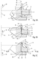
- the crown 2 has a part annular 15 extending axially beyond the teeth 8 in the axial direction 16 away from the radial surface complementary 14 and directed towards the rotor 7, and the crown 2 is fixed to the handwheel 1 at the axial end 17 of this annular part 15.
- the axial end 17 has a flange interior 18, projecting radially inward towards axis 5, the inner flange 18 being limited internally by an inner peripheral surface cylindrical 23 adapted to be in contact with the surface device 10 of the steering wheel 1 and to be fixed on this one.
- This embodiment is preferably fixed to the flywheel 1 by shrinking, as shown in Figure 2B.
- the annular part 15 is fixed by the peripheral surface 23 from its axial end 17 to the peripheral surface 10 of the steering wheel 1 by a cord of weld shown schematically in 19 in the figure.
- the rest of the surface substantially complementary cylindrical 13 is shaped so as to be spaced radially from the cylindrical surface 10 of the handwheel 1 to give the required radial flexibility to the crown 2.
- the region 14a of the complementary radial surface 14 of crown 2 adapted to be in contact with the surface radial 11 of the flywheel 1 extends radially over a low height from the circular edge 20 constituting in the figures the corresponding corner, that is to say the lower right corner, from the axial section of the crowned.
- region 11a of the radial surface 11 of the flywheel 1 adapted to be in contact with the region 14a of the crown extends radially at a low height from the surface peripheral 10 so as to be in sliding contact with the region 14a of the complementary radial surface 14 of the crown 2 of small radial dimension.
- the radial surface 11 is extended by a very flared conical surface 21 with the same axis 5 which facilitates the installation of crown 2 on the steering wheel 1.
- a thin coating attached to the radial surface 11 of the steering wheel 1, of a material facilitating contact sliding between the radial surface 11 and the surface complementary radial 14, for example of an elastomer or a plastomer.
- the inner peripheral surface complementary to crown 2 has a dimension axial preferably corresponding substantially to that teeth 8.
- the crown 2 is fixed on the flywheel 1 in region 23 of the peripheral surface complementary 13 furthest from the radial surface complementary 14, for example by welding or by hooping.
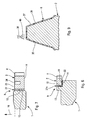
- the crown 2 also has a groove annular 24 starting from the surface 25 limiting axially the crown 2 in the axial direction 16 towards the rotor 7, opposite the complementary radial surface 14, and extending axially towards said radial surface complementary 14 on part of the axial dimension crown 2.
- Region 23 shown in Figure 3A has a sufficient axial dimension to allow attachment by hooping of the crown 2 on the surface 10 of the steering wheel 1.
- the crown 2 is fixed to the steering wheel 1 by a weld bead 19 to the axial end of the region 23 opposite the surface complementary radial 14.
- the contact region 11a of the radial surface 11 of the flywheel 1 is arranged radially outside the peripheral surface 10, and extends over a small radial height. It has a coating 22 in elastomer or plastomer of small thickness allowing sliding contact with region 14a of the surface complementary radial 14 of the crown 2.
- the steering wheel 1 does not not extend radially outward beyond the region 11a, which leaves the crown free deformation during a starting operation.
- the steering wheel has a metal element intermediate ring 26 on which the crown 2, in any conventional manner, by for example by screwing, shrinking or welding.
- the intermediate annular element 26 comprises the complementary inner peripheral surface 13 and the complementary radial surface 14. This annular element intermediate 26 is fixed on the steering wheel 1 to its axial end away from the radial surface complementary 14 as if the intermediate element 26 was an integral part of crown 2. It is fixed in any known manner at the wheel 1.
- the element intermediate 26 has an axial length greater than that of the crown 2. It is fixed to the steering wheel 1 by a weld bead 19 formed at its axial end 17 distant from the complementary radial surface 14.
- the flywheel 1 comprises an annular ring 27 in a deformable material, for example an elastomer or plastomer, extending axially along the surface complementary device 13 of the crown 2.
- the ring 27 is bonded or adhered in a known manner any side on the peripheral surface 10 of the steering wheel 1 and on the other side on the peripheral surface 13 of crown 2.
- This annular ring 27 necessarily has a some thickness sufficient to communicate to the crown 2 freedom of deformation compared to steering wheel 1 to obtain the effects sought by the present invention.
- a coating 22 of elastomer or plastomer is fixed, for example, on the radial surface 11 to allow sliding contact with the surface complementary radial 14 of the crown 2.
- the annular ring 27a has in radial section a section L and has a bonded radial wall 32 on one side on the radial surface 11 of the support 1 and of the other side on the complementary radial surface 14 of crown 2.
- the ring 27a can thus be produced easily by pressure injection of the elastomer into the L-shaped space between support 1 and the crown 2.
- the peripheral part 3 of the steering wheel 1 comprises only the cylindrical surface 10, without any wall radial.
- the crown 2 In the absence of the conventional wall 11, the crown 2 must be fixed on the support by means adapted to collect all of said axial force.
- annular ring 27 made of viscoelastic material is adhered on one side to the peripheral surface 10 of the steering wheel 1, on the other side on the peripheral surface 13 crown 2.
- the crown 2 comprises the annular groove 24 described above.
- the annular ring 27 could also be in metal in the case of the embodiment described below with reference to Figure 8.
- the crown 2 is fixed to the handwheel 1 of preferably only according to peripheral sectors, shown schematically at 28 in Figure 1, regularly distributed around the axis 5 of the steering wheel 1, leaving the diametrically opposite sectors 29 corresponding to compression zones of a heat engine equipped with flywheel considered, and / or sectors 30 diametrically opposite corresponding to the expansion zones of said motor, sectors 29 and 30 being easily identified by relative to the top dead center which is conventionally spotted on any steering wheel. This is especially understood in the case of fixing by welding (see figure 1) or by shrinking (see Figure 6).
- each sector 29, 30 of compression or trigger being located between two sectors 28 of adjacent fixing.
- the peripheral surface of the steering wheel 1 has a recess 31 at the right of each of the two sectors 29 corresponding to the two compression zones and / or each of the two sectors 30 corresponding to the two zones of relaxation.
- the recesses 31 are made in a way any known, and are for example flats made during molding or by milling, or grooves of any peripheral shape.
- the crown 2 which is not blocked on the steering wheel at the recesses 31 has a additional radial flexibility which decreases stresses and wear usually suffered by the crown in sectors 29 and 30 corresponding to compression and relaxation zones.
- connection systems a crown 2 on a steering wheel 1.
- Some of these modes connecting means also fixing means as far away from the radial surface as possible complementary 14 to the crown giving to the crown 2 compared to the flywheel 1 radial flexibility facilitated by sliding contact over a height generally weak radial between the radial surface complementary 14 to crown 2 and the radial surface 11 of steering wheel 1.
- the linking system provides a link of the crown on the steering wheel or its support which relates to at least partially the outer peripheral surface 10 of the steering wheel 1 and the inner peripheral surface 13 crown 2.
- the Applicant continued its research and his efforts to improve this resistance target of the crown while reducing the level of noise generated by a starting operation.
- This coating 37 can obviously also cover the surface 38 between two adjacent teeth 8 (see Figure 1) or be limited to faces 35 and 36.
- Such a coating is known in itself. he can be for example made by means of a varnish of SDA ® type slip marketed by the company SURFACES ® TECHNIQUES bringing parts to the surface treated with solid lubricants, such as disulfide molybdenum, in a thermosetting matrix based of epoxy, phenolic, silicone, etc. resins, only or mixed.
- solid lubricants such as disulfide molybdenum
- Such a coating can alternatively be by example the result of a known surface treatment under the trade name SULF BT ® of the same company TECHNIQUES SURFACES TS ®, produced by electrolysis anodic in a bath of molten salts based on alkali thiocyanates. This treatment performs on surfaces treated a micro-layer, having a thickness from about 7 to 8 microns, completely iron sulfide embedded in the base metal.
- Such a self-lubricating coating can obviously be associated with lubrication by a suitable oil or grease applied by any known means of lubrication schematically at 39 in FIG. 9, for example a nozzle of spraying oil droplets 40.
Landscapes
- Engineering & Computer Science (AREA)
- General Engineering & Computer Science (AREA)
- Chemical & Material Sciences (AREA)
- Mechanical Engineering (AREA)
- Life Sciences & Earth Sciences (AREA)
- Health & Medical Sciences (AREA)
- Physics & Mathematics (AREA)
- Immunology (AREA)
- Chemical Kinetics & Catalysis (AREA)
- Electrochemistry (AREA)
- Pathology (AREA)
- Analytical Chemistry (AREA)
- Biochemistry (AREA)
- General Health & Medical Sciences (AREA)
- General Physics & Mathematics (AREA)
- Molecular Biology (AREA)
- Combustion & Propulsion (AREA)
- Gears, Cams (AREA)
- Connection Of Motors, Electrical Generators, Mechanical Devices, And The Like (AREA)
- Shafts, Cranks, Connecting Bars, And Related Bearings (AREA)
- Lubricants (AREA)
- Primary Cells (AREA)
- Ignition Installations For Internal Combustion Engines (AREA)
Applications Claiming Priority (4)
| Application Number | Priority Date | Filing Date | Title |
|---|---|---|---|
| FR9912240A FR2799253A1 (fr) | 1999-09-30 | 1999-09-30 | Systeme de liaison d'une couronne dentee de demarreur sur un support lie a l'arbre de sortie d'un moteur thermique |
| FR9916175 | 1999-12-21 | ||
| FR9912240 | 1999-12-21 | ||
| FR9916175A FR2799254B1 (fr) | 1999-09-30 | 1999-12-21 | Systeme de liaison d'une couronne dentee de demarreur sur un support lie a l'arbre de sortie d'un moteur thermique |
Publications (3)
| Publication Number | Publication Date |
|---|---|
| EP1089021A2 true EP1089021A2 (de) | 2001-04-04 |
| EP1089021A3 EP1089021A3 (de) | 2001-06-20 |
| EP1089021B1 EP1089021B1 (de) | 2004-03-17 |
Family
ID=26235124
Family Applications (1)
| Application Number | Title | Priority Date | Filing Date |
|---|---|---|---|
| EP00402629A Expired - Lifetime EP1089021B1 (de) | 1999-09-30 | 2000-09-21 | Schwungrad eines Verbrennungmotors mit Anlasser-Zahnkranzes |
Country Status (10)
| Country | Link |
|---|---|
| US (2) | US6782773B1 (de) |
| EP (1) | EP1089021B1 (de) |
| JP (1) | JP3672017B2 (de) |
| KR (1) | KR20010067265A (de) |
| AT (1) | ATE262123T1 (de) |
| BR (1) | BR0004526A (de) |
| CA (1) | CA2321158A1 (de) |
| DE (2) | DE20010377U1 (de) |
| ES (1) | ES2214234T3 (de) |
| FR (1) | FR2799254B1 (de) |
Cited By (1)
| Publication number | Priority date | Publication date | Assignee | Title |
|---|---|---|---|---|
| CN108000077A (zh) * | 2017-12-08 | 2018-05-08 | 东莞市领亚自动化科技有限公司 | 一种行星减速器齿圈的制造方法及使用该齿圈的行星减速器 |
Families Citing this family (24)
| Publication number | Priority date | Publication date | Assignee | Title |
|---|---|---|---|---|
| FR2833057B1 (fr) * | 2001-12-04 | 2004-07-02 | Defontaine Sa | Volant de demarrage anti-bruit |
| JP3799549B2 (ja) * | 2002-07-25 | 2006-07-19 | 愛知機械工業株式会社 | 変速装置用ギヤの製造方法 |
| DE102006006955B3 (de) * | 2006-02-14 | 2007-08-30 | Benteler Automobiltechnik Gmbh | Kraftfahrzeug-Strukturbauteil |
| JP4179349B2 (ja) | 2006-06-23 | 2008-11-12 | トヨタ自動車株式会社 | リングギヤ、内燃機関始動回転力伝達機構及びリングギヤ製造方法 |
| US7658124B2 (en) * | 2006-07-27 | 2010-02-09 | Caterpillar Inc. | Compliant gear assembly and work machine using same |
| US8225689B2 (en) * | 2006-07-27 | 2012-07-24 | Caterpillar Inc. | Compliant gear assembly, engine and gear train operating method |
| DE102008042444A1 (de) * | 2008-09-29 | 2010-04-01 | Robert Bosch Gmbh | Startergetriebe mit Gleitlackbeschichtung |
| JP2010236608A (ja) * | 2009-03-31 | 2010-10-21 | Toyota Central R&D Labs Inc | ドライブプレート |
| DE102009027856A1 (de) * | 2009-07-21 | 2011-01-27 | Robert Bosch Gmbh | Startergetriebe mit Trockenschmierung |
| DE102009046988A1 (de) | 2009-11-23 | 2011-05-26 | Robert Bosch Gmbh | Geräuschoptimierte Startvorrichtung |
| JP5363422B2 (ja) * | 2010-06-01 | 2013-12-11 | トヨタ自動車株式会社 | 車両用スタータリングギヤ |
| WO2011158330A1 (ja) * | 2010-06-15 | 2011-12-22 | トヨタ自動車株式会社 | リングギアとデフケースの溶接構造 |
| DE102011001881A1 (de) * | 2011-04-07 | 2012-10-11 | Mühlhoff Umformtechnik GmbH | Verfahren zur Herstellung eines Schwungrads |
| DE102011076656A1 (de) * | 2011-05-30 | 2012-12-06 | Zf Friedrichshafen Ag | Baugruppe eines Getriebes |
| ES2442451B2 (es) * | 2012-07-10 | 2014-05-23 | Universitat Politècnica De Catalunya | Procedimiento y dispositivo para prevenir el desgaste excesivo en engranajes |
| US9982748B2 (en) * | 2012-12-12 | 2018-05-29 | Magna International | Flexplates and method for capacitor discharge welding of flexplates |
| DE102014111581A1 (de) | 2014-08-13 | 2016-02-18 | Mühlhoff Umformtechnik GmbH | Verfahren zur Herstellung eines Schwungrads |
| DE202014011620U1 (de) | 2014-08-13 | 2023-11-30 | Mühlhoff Umformtechnik Gesellschaft mit beschränkter Haftung | Schwungrad |
| CN106122440A (zh) * | 2016-08-15 | 2016-11-16 | 常州市武进金城齿轮有限公司 | 加固齿轮 |
| KR101765644B1 (ko) | 2016-10-24 | 2017-08-07 | 현대자동차 주식회사 | 하이브리드 변속기용 엔진 클러치의 모터 연결구조 |
| DE102017109726A1 (de) * | 2017-05-05 | 2018-11-08 | Mühlhoff Umformtechnik GmbH | Verfahren zur Herstellung eines Schwungrads |
| US20190219147A1 (en) * | 2018-01-17 | 2019-07-18 | ILJIN USA Corporation | Gear for a torque transmission device and method for making the gear |
| DE102019130428A1 (de) * | 2019-11-12 | 2021-05-12 | Seg Automotive Germany Gmbh | Starter für eine Brennkraftmaschine |
| DE102022129150A1 (de) | 2022-11-04 | 2024-05-08 | Bayerische Motoren Werke Aktiengesellschaft | Aufgeklebtes Zahnrad |
Citations (10)
| Publication number | Priority date | Publication date | Assignee | Title |
|---|---|---|---|---|
| FR788061A (fr) * | 1934-05-03 | 1935-10-03 | Bosch Robert | Roue dentée à denture rapportée, notamment pour volants de moteurs à combustion interne |
| US2060565A (en) * | 1933-09-15 | 1936-11-10 | Gen Motors Corp | Flywheel |
| US3854418A (en) * | 1972-03-03 | 1974-12-17 | Bertin & Cie | Improvements in rack-and-pinion systems |
| US4109545A (en) * | 1977-01-26 | 1978-08-29 | Enakichi Hayasaka | Noiseless spur gears |
| DE3132503A1 (de) * | 1981-08-18 | 1983-03-10 | Johann 8201 Bad Feilnbach Schmuck | "brennkraftmaschine" |
| JPS62137443A (ja) * | 1985-12-06 | 1987-06-20 | Yamaha Motor Co Ltd | ダンパ付き歯車 |
| JPH0415352A (ja) * | 1990-05-09 | 1992-01-20 | Mazda Motor Corp | エンジンのスタータリングギア固定構造 |
| JPH0463965A (ja) * | 1990-06-29 | 1992-02-28 | Kubota Corp | エンジンの始動用リングギア固定支持装置 |
| JPH07119600A (ja) * | 1993-10-15 | 1995-05-09 | Nippondenso Co Ltd | 遊星歯車減速機構付スタ−タ |
| US5911788A (en) * | 1998-02-20 | 1999-06-15 | Sundstrand Corporation | Compliant gear |
Family Cites Families (14)
| Publication number | Priority date | Publication date | Assignee | Title |
|---|---|---|---|---|
| US2704465A (en) * | 1955-03-22 | Self-lubricating toothed or lobed wheel | ||
| US2885870A (en) * | 1957-04-18 | 1959-05-12 | Jaklitsch Franz | Torque transmitting device |
| US3200659A (en) * | 1963-04-24 | 1965-08-17 | John Dolza | Rotary motion transmitting mechanism for internal combustion engines and the like |
| US3262435A (en) * | 1964-05-25 | 1966-07-26 | John R Cribbs | Automatic variable valve timing device for internal combustion engines |
| US3377875A (en) * | 1966-05-09 | 1968-04-16 | Gen Motors Corp | Chain drive power transmitting mechanism |
| US4151873A (en) * | 1978-01-25 | 1979-05-01 | The United States Of America As Represented By The United States Department Of Energy | Regenerator for gas turbine engine |
| DE3345541A1 (de) * | 1983-12-16 | 1985-07-18 | Sachs Systemtechnik Gmbh, 8720 Schweinfurt | Geteiltes schwungrad |
| JPH01120481A (ja) | 1987-11-05 | 1989-05-12 | Toshiba Corp | 固体潤滑歯車装置 |
| JP2532365Y2 (ja) * | 1988-04-18 | 1997-04-16 | トヨタ自動車株式会社 | 回転軸用ダンパ |
| JPH0434259A (ja) * | 1990-05-30 | 1992-02-05 | Hitachi Ltd | 真空用歯車 |
| US5251725A (en) * | 1992-07-07 | 1993-10-12 | Castrol Limited | Lubrication of power drive comprising large diameter gear |
| US5307705A (en) * | 1993-02-09 | 1994-05-03 | Fenelon Paul J | Stress dissipation gear and method of making same |
| JPH09126302A (ja) * | 1995-10-31 | 1997-05-13 | Kioritz Corp | 歯 車 |
| JPH09133199A (ja) | 1995-11-09 | 1997-05-20 | Mitsubishi Heavy Ind Ltd | 自給油型歯車 |
-
1999
- 1999-12-21 FR FR9916175A patent/FR2799254B1/fr not_active Expired - Fee Related
-
2000
- 2000-06-09 DE DE20010377U patent/DE20010377U1/de not_active Expired - Lifetime
- 2000-09-21 EP EP00402629A patent/EP1089021B1/de not_active Expired - Lifetime
- 2000-09-21 DE DE60008991T patent/DE60008991T2/de not_active Expired - Lifetime
- 2000-09-21 ES ES00402629T patent/ES2214234T3/es not_active Expired - Lifetime
- 2000-09-21 AT AT00402629T patent/ATE262123T1/de not_active IP Right Cessation
- 2000-09-27 CA CA002321158A patent/CA2321158A1/fr not_active Abandoned
- 2000-09-28 US US09/671,624 patent/US6782773B1/en not_active Expired - Fee Related
- 2000-09-28 BR BR0004526-8A patent/BR0004526A/pt not_active Application Discontinuation
- 2000-09-29 KR KR1020000057417A patent/KR20010067265A/ko active IP Right Grant
- 2000-09-29 JP JP2000298147A patent/JP3672017B2/ja not_active Expired - Fee Related
-
2004
- 2004-03-19 US US10/804,755 patent/US20040237707A1/en not_active Abandoned
Patent Citations (10)
| Publication number | Priority date | Publication date | Assignee | Title |
|---|---|---|---|---|
| US2060565A (en) * | 1933-09-15 | 1936-11-10 | Gen Motors Corp | Flywheel |
| FR788061A (fr) * | 1934-05-03 | 1935-10-03 | Bosch Robert | Roue dentée à denture rapportée, notamment pour volants de moteurs à combustion interne |
| US3854418A (en) * | 1972-03-03 | 1974-12-17 | Bertin & Cie | Improvements in rack-and-pinion systems |
| US4109545A (en) * | 1977-01-26 | 1978-08-29 | Enakichi Hayasaka | Noiseless spur gears |
| DE3132503A1 (de) * | 1981-08-18 | 1983-03-10 | Johann 8201 Bad Feilnbach Schmuck | "brennkraftmaschine" |
| JPS62137443A (ja) * | 1985-12-06 | 1987-06-20 | Yamaha Motor Co Ltd | ダンパ付き歯車 |
| JPH0415352A (ja) * | 1990-05-09 | 1992-01-20 | Mazda Motor Corp | エンジンのスタータリングギア固定構造 |
| JPH0463965A (ja) * | 1990-06-29 | 1992-02-28 | Kubota Corp | エンジンの始動用リングギア固定支持装置 |
| JPH07119600A (ja) * | 1993-10-15 | 1995-05-09 | Nippondenso Co Ltd | 遊星歯車減速機構付スタ−タ |
| US5911788A (en) * | 1998-02-20 | 1999-06-15 | Sundstrand Corporation | Compliant gear |
Non-Patent Citations (4)
| Title |
|---|
| PATENT ABSTRACTS OF JAPAN vol. 011, no. 360 (M-645), 25 novembre 1987 (1987-11-25) & JP 62 137443 A (YAMAHA MOTOR CO LTD), 20 juin 1987 (1987-06-20) * |
| PATENT ABSTRACTS OF JAPAN vol. 016, no. 169 (M-1239), 23 avril 1992 (1992-04-23) -& JP 04 015352 A (MAZDA MOTOR CORP), 20 janvier 1992 (1992-01-20) * |
| PATENT ABSTRACTS OF JAPAN vol. 016, no. 262 (M-1265), 15 juin 1992 (1992-06-15) -& JP 04 063965 A (KUBOTA CORP), 28 février 1992 (1992-02-28) * |
| PATENT ABSTRACTS OF JAPAN vol. 1995, no. 08, 29 septembre 1995 (1995-09-29) -& JP 07 119600 A (NIPPONDENSO CO LTD), 9 mai 1995 (1995-05-09) * |
Cited By (1)
| Publication number | Priority date | Publication date | Assignee | Title |
|---|---|---|---|---|
| CN108000077A (zh) * | 2017-12-08 | 2018-05-08 | 东莞市领亚自动化科技有限公司 | 一种行星减速器齿圈的制造方法及使用该齿圈的行星减速器 |
Also Published As
| Publication number | Publication date |
|---|---|
| DE20010377U1 (de) | 2000-09-14 |
| KR20010067265A (ko) | 2001-07-12 |
| JP3672017B2 (ja) | 2005-07-13 |
| US6782773B1 (en) | 2004-08-31 |
| DE60008991D1 (de) | 2004-04-22 |
| EP1089021A3 (de) | 2001-06-20 |
| BR0004526A (pt) | 2001-04-17 |
| FR2799254B1 (fr) | 2003-05-30 |
| EP1089021B1 (de) | 2004-03-17 |
| ATE262123T1 (de) | 2004-04-15 |
| CA2321158A1 (fr) | 2001-03-30 |
| ES2214234T3 (es) | 2004-09-16 |
| US20040237707A1 (en) | 2004-12-02 |
| FR2799254A1 (fr) | 2001-04-06 |
| DE60008991T2 (de) | 2005-01-05 |
| JP2001153009A (ja) | 2001-06-05 |
Similar Documents
| Publication | Publication Date | Title |
|---|---|---|
| EP1089021B1 (de) | Schwungrad eines Verbrennungmotors mit Anlasser-Zahnkranzes | |
| EP1058786B1 (de) | Anlasser für kraftfahrzeug mit untersetzungsgetriebe mit torsionsdämpfungformenden mitteln | |
| FR2632698A1 (fr) | Dispositif pour amortir des vibrations | |
| FR2722552A1 (fr) | Dispositif de transmission de couple de rotation qui fonctonne en cooperation avec un embrayage a friction | |
| FR2485130A1 (fr) | Dispositif d'embrayage a volant d'inertie | |
| FR2763106A1 (fr) | Dispositif de transmission de couple | |
| FR2690211A1 (fr) | Dispositif de transmission de couple. | |
| EP0715695B1 (de) | Dämpfungsschwingrad, insbesondere für kraftfahrzeuge | |
| FR2722260A1 (fr) | Dispositif d'amortissement d'oscillations en torsion | |
| FR2734618A1 (fr) | Fixation d'un volant moteur au vilebrequin d'un moteur | |
| FR2785343A1 (fr) | Debrayeur central a commande hydraulique realise comme un cylindre recepteur pour un embrayage commande de separation d'un vehicule | |
| EP3947958B1 (de) | Hydraulische maschine mit einem verbesserten gleitlager | |
| FR2747168A1 (fr) | Amortisseur de torsion comportant une amenee de lubrifiant pour un satellite | |
| EP1645773A1 (de) | Hydraulisches schwingungsdämpfendes Lager für ein Kraftfahrzeug und Herstellungsverfahren einer solchen Vorrichtung | |
| FR2687749A1 (fr) | Dispositif amortisseur de torsion, notamment double volant amortisseur et disque de friction d'embrayage, pour vehicules automobiles. | |
| FR2706963A1 (de) | ||
| EP0685045A1 (de) | Torsionsdämfper, insbesondere für kraftfahrzeuge mit ringförmigem abgedichtetem gehäuse | |
| FR2782766A1 (fr) | Amortisseur pour un embrayage de coupure d'un embrayage hydrodynamique | |
| FR2660038A1 (fr) | Double volant amortisseur, notamment pour vehicule automobile. | |
| FR2716512A1 (fr) | Dispositif à volant, comportant un joint à labyrinthe, dans une transmission de véhicule automobile . | |
| EP4008929B1 (de) | Planetenbaugruppe, planetensatz mit einer solchen baugruppe und getriebe | |
| EP0921307B1 (de) | Anlasser für Kraftfahrzeug mit Untersetzungsgetriebe und Stossbegrenzervorrichtung | |
| EP1369620A2 (de) | Anordnung einer Trägheitsmasse auf einer Rotationsachse sowie Getriebe mit einer derartigen Anordnung | |
| FR2761746A1 (fr) | Amortisseur de vibrations de torsions a palier lisse | |
| WO2002021021A1 (fr) | Appareil d'accouplement hydrocinetique, notamment pour vehicule automobile |
Legal Events
| Date | Code | Title | Description |
|---|---|---|---|
| PUAI | Public reference made under article 153(3) epc to a published international application that has entered the european phase |
Free format text: ORIGINAL CODE: 0009012 |
|
| AK | Designated contracting states |
Kind code of ref document: A2 Designated state(s): AT BE CH CY DE DK ES FI FR GB GR IE IT LI LU MC NL PT SE |
|
| AX | Request for extension of the european patent |
Free format text: AL;LT;LV;MK;RO;SI |
|
| PUAL | Search report despatched |
Free format text: ORIGINAL CODE: 0009013 |
|
| AK | Designated contracting states |
Kind code of ref document: A3 Designated state(s): AT BE CH CY DE DK ES FI FR GB GR IE IT LI LU MC NL PT SE |
|
| AX | Request for extension of the european patent |
Free format text: AL;LT;LV;MK;RO;SI |
|
| 17P | Request for examination filed |
Effective date: 20011128 |
|
| AKX | Designation fees paid |
Free format text: AT BE CH CY DE DK ES FI FR GB GR IE IT LI LU MC NL PT SE |
|
| 17Q | First examination report despatched |
Effective date: 20021211 |
|
| RTI1 | Title (correction) |
Free format text: FLYWHEEL OF AN INTERNAL COMBUSTION ENGINE WITH A STARTING GEAR RING |
|
| GRAP | Despatch of communication of intention to grant a patent |
Free format text: ORIGINAL CODE: EPIDOSNIGR1 |
|
| RTI1 | Title (correction) |
Free format text: FLYWHEEL OF AN INTERNAL COMBUSTION ENGINE WITH A STARTING GEAR RING |
|
| GRAS | Grant fee paid |
Free format text: ORIGINAL CODE: EPIDOSNIGR3 |
|
| GRAA | (expected) grant |
Free format text: ORIGINAL CODE: 0009210 |
|
| AK | Designated contracting states |
Kind code of ref document: B1 Designated state(s): AT BE CH CY DE DK ES FI FR GB GR IE IT LI LU MC NL PT SE |
|
| PG25 | Lapsed in a contracting state [announced via postgrant information from national office to epo] |
Ref country code: FI Free format text: LAPSE BECAUSE OF FAILURE TO SUBMIT A TRANSLATION OF THE DESCRIPTION OR TO PAY THE FEE WITHIN THE PRESCRIBED TIME-LIMIT Effective date: 20040317 Ref country code: CY Free format text: LAPSE BECAUSE OF FAILURE TO SUBMIT A TRANSLATION OF THE DESCRIPTION OR TO PAY THE FEE WITHIN THE PRESCRIBED TIME-LIMIT Effective date: 20040317 Ref country code: IE Free format text: LAPSE BECAUSE OF FAILURE TO SUBMIT A TRANSLATION OF THE DESCRIPTION OR TO PAY THE FEE WITHIN THE PRESCRIBED TIME-LIMIT Effective date: 20040317 Ref country code: NL Free format text: LAPSE BECAUSE OF FAILURE TO SUBMIT A TRANSLATION OF THE DESCRIPTION OR TO PAY THE FEE WITHIN THE PRESCRIBED TIME-LIMIT Effective date: 20040317 Ref country code: AT Free format text: LAPSE BECAUSE OF FAILURE TO SUBMIT A TRANSLATION OF THE DESCRIPTION OR TO PAY THE FEE WITHIN THE PRESCRIBED TIME-LIMIT Effective date: 20040317 |
|
| REG | Reference to a national code |
Ref country code: GB Ref legal event code: FG4D Free format text: NOT ENGLISH |
|
| REG | Reference to a national code |
Ref country code: CH Ref legal event code: EP |
|
| GBT | Gb: translation of ep patent filed (gb section 77(6)(a)/1977) |
Effective date: 20040317 |
|
| REG | Reference to a national code |
Ref country code: IE Ref legal event code: FG4D Free format text: FRENCH |
|
| REF | Corresponds to: |
Ref document number: 60008991 Country of ref document: DE Date of ref document: 20040422 Kind code of ref document: P |
|
| PG25 | Lapsed in a contracting state [announced via postgrant information from national office to epo] |
Ref country code: SE Free format text: LAPSE BECAUSE OF FAILURE TO SUBMIT A TRANSLATION OF THE DESCRIPTION OR TO PAY THE FEE WITHIN THE PRESCRIBED TIME-LIMIT Effective date: 20040617 Ref country code: GR Free format text: LAPSE BECAUSE OF FAILURE TO SUBMIT A TRANSLATION OF THE DESCRIPTION OR TO PAY THE FEE WITHIN THE PRESCRIBED TIME-LIMIT Effective date: 20040617 Ref country code: DK Free format text: LAPSE BECAUSE OF FAILURE TO SUBMIT A TRANSLATION OF THE DESCRIPTION OR TO PAY THE FEE WITHIN THE PRESCRIBED TIME-LIMIT Effective date: 20040617 |
|
| NLV1 | Nl: lapsed or annulled due to failure to fulfill the requirements of art. 29p and 29m of the patents act | ||
| REG | Reference to a national code |
Ref country code: ES Ref legal event code: FG2A Ref document number: 2214234 Country of ref document: ES Kind code of ref document: T3 |
|
| PG25 | Lapsed in a contracting state [announced via postgrant information from national office to epo] |
Ref country code: LU Free format text: LAPSE BECAUSE OF NON-PAYMENT OF DUE FEES Effective date: 20040921 |
|
| PG25 | Lapsed in a contracting state [announced via postgrant information from national office to epo] |
Ref country code: LI Free format text: LAPSE BECAUSE OF NON-PAYMENT OF DUE FEES Effective date: 20040930 Ref country code: MC Free format text: LAPSE BECAUSE OF NON-PAYMENT OF DUE FEES Effective date: 20040930 Ref country code: CH Free format text: LAPSE BECAUSE OF NON-PAYMENT OF DUE FEES Effective date: 20040930 |
|
| REG | Reference to a national code |
Ref country code: IE Ref legal event code: FD4D |
|
| PLBE | No opposition filed within time limit |
Free format text: ORIGINAL CODE: 0009261 |
|
| STAA | Information on the status of an ep patent application or granted ep patent |
Free format text: STATUS: NO OPPOSITION FILED WITHIN TIME LIMIT |
|
| 26N | No opposition filed |
Effective date: 20041220 |
|
| REG | Reference to a national code |
Ref country code: CH Ref legal event code: PL |
|
| PG25 | Lapsed in a contracting state [announced via postgrant information from national office to epo] |
Ref country code: PT Free format text: LAPSE BECAUSE OF NON-PAYMENT OF DUE FEES Effective date: 20040817 |
|
| PGFP | Annual fee paid to national office [announced via postgrant information from national office to epo] |
Ref country code: DE Payment date: 20100915 Year of fee payment: 11 |
|
| PGFP | Annual fee paid to national office [announced via postgrant information from national office to epo] |
Ref country code: GB Payment date: 20110921 Year of fee payment: 12 Ref country code: FR Payment date: 20111005 Year of fee payment: 12 |
|
| PGFP | Annual fee paid to national office [announced via postgrant information from national office to epo] |
Ref country code: IT Payment date: 20110913 Year of fee payment: 12 |
|
| PGFP | Annual fee paid to national office [announced via postgrant information from national office to epo] |
Ref country code: BE Payment date: 20110930 Year of fee payment: 12 Ref country code: ES Payment date: 20111017 Year of fee payment: 12 |
|
| BERE | Be: lapsed |
Owner name: S.A. *DEFONTAINE Effective date: 20120930 |
|
| GBPC | Gb: european patent ceased through non-payment of renewal fee |
Effective date: 20120921 |
|
| REG | Reference to a national code |
Ref country code: FR Ref legal event code: ST Effective date: 20130531 |
|
| REG | Reference to a national code |
Ref country code: DE Ref legal event code: R119 Ref document number: 60008991 Country of ref document: DE Effective date: 20130403 |
|
| PG25 | Lapsed in a contracting state [announced via postgrant information from national office to epo] |
Ref country code: GB Free format text: LAPSE BECAUSE OF NON-PAYMENT OF DUE FEES Effective date: 20120921 Ref country code: BE Free format text: LAPSE BECAUSE OF NON-PAYMENT OF DUE FEES Effective date: 20120930 Ref country code: DE Free format text: LAPSE BECAUSE OF NON-PAYMENT OF DUE FEES Effective date: 20130403 |
|
| PG25 | Lapsed in a contracting state [announced via postgrant information from national office to epo] |
Ref country code: IT Free format text: LAPSE BECAUSE OF NON-PAYMENT OF DUE FEES Effective date: 20120921 Ref country code: FR Free format text: LAPSE BECAUSE OF NON-PAYMENT OF DUE FEES Effective date: 20121001 |
|
| REG | Reference to a national code |
Ref country code: ES Ref legal event code: FD2A Effective date: 20131021 |
|
| PG25 | Lapsed in a contracting state [announced via postgrant information from national office to epo] |
Ref country code: ES Free format text: LAPSE BECAUSE OF NON-PAYMENT OF DUE FEES Effective date: 20120922 |