EP0921307B1 - Anlasser für Kraftfahrzeug mit Untersetzungsgetriebe und Stossbegrenzervorrichtung - Google Patents
Anlasser für Kraftfahrzeug mit Untersetzungsgetriebe und Stossbegrenzervorrichtung Download PDFInfo
- Publication number
- EP0921307B1 EP0921307B1 EP19980402013 EP98402013A EP0921307B1 EP 0921307 B1 EP0921307 B1 EP 0921307B1 EP 19980402013 EP19980402013 EP 19980402013 EP 98402013 A EP98402013 A EP 98402013A EP 0921307 B1 EP0921307 B1 EP 0921307B1
- Authority
- EP
- European Patent Office
- Prior art keywords
- ring
- starter
- toothed
- skirt
- starter according
- Prior art date
- Legal status (The legal status is an assumption and is not a legal conclusion. Google has not performed a legal analysis and makes no representation as to the accuracy of the status listed.)
- Expired - Lifetime
Links
Images

Classifications
-
- F—MECHANICAL ENGINEERING; LIGHTING; HEATING; WEAPONS; BLASTING
- F02—COMBUSTION ENGINES; HOT-GAS OR COMBUSTION-PRODUCT ENGINE PLANTS
- F02N—STARTING OF COMBUSTION ENGINES; STARTING AIDS FOR SUCH ENGINES, NOT OTHERWISE PROVIDED FOR
- F02N15/00—Other power-operated starting apparatus; Component parts, details, or accessories, not provided for in, or of interest apart from groups F02N5/00 - F02N13/00
- F02N15/02—Gearing between starting-engines and started engines; Engagement or disengagement thereof
- F02N15/04—Gearing between starting-engines and started engines; Engagement or disengagement thereof the gearing including disengaging toothed gears
- F02N15/043—Gearing between starting-engines and started engines; Engagement or disengagement thereof the gearing including disengaging toothed gears the gearing including a speed reducer
- F02N15/046—Gearing between starting-engines and started engines; Engagement or disengagement thereof the gearing including disengaging toothed gears the gearing including a speed reducer of the planetary type
Definitions
- the present invention relates to a starter for motor vehicle.
- the invention relates more particularly to a starter of the type comprising an electric motor of which the output shaft rotates a coaxial launcher with interposition of a gear reducer, in particular of the type with planetary gear.
- the friction device includes a annular friction disc which is rotatably linked to the crown and which is in axial abutment against the internal face of one of the flanges of the case against which the friction disc is stressed axially by a frustoconical elastic washer.
- This design therefore calls for at least two additional components, compared to a train epicyclic without torque limiting device, i.e. the friction washer and elastic frustoconical washer.
- the object of the invention is to propose a new design of a starter of the type mentioned previously which remedies the disadvantages which have just been mentioned.
- the invention provides a starter for motor vehicle of the type comprising a housing in which is arranged an electric motor whose output shaft drives in rotation a coaxial launcher with the interposition of a reducer having an internally toothed crown which is mounted in a housing cavity in which it is immobilized in rotation and which comprises an annular skirt cylindrical toothed internally closed at one of its axial ends by a radial wall pierced at its center for the passage of a gearbox output shaft, the crown toothed comprising an elastically deformable zone in twist which is arranged at one of the axial ends of the internally toothed skirt to intervene between the latter and an adjacent part of the crown comprising means for immobilizing the crown in rotation in its cavity, characterized in that the deformable zone elastically consists of a series of link arms elastically deformable, of substantially axial orientation, which connect the axial end of the toothed skirt to the part adjacent to the ring gear comprising the means immobilization in rotation.
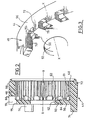
- Part 1 of a motor vehicle starter 10 of the type comprising a electric motor 12 whose rotor 14 is mounted rotating, around an axis X-X inside a rear part 16 of the starter housing which is completed by a front part 18 hood-shaped.
- the upper part (not shown in detail) of the starter 10 includes an electromagnetic contactor which, by means of a fork 20 in the form of a fork, acts known manner on a launcher 22 which is slidably mounted on a starter shaft 24 coaxial with the output shaft 26 of the engine electric 12.
- the output shaft 26 of the electric motor 12, linked at rotation to rotor 14, projects axially forwards beyond of the front face 28 of the stator 30 and it rotates a pinion 32 which is the sun pinion of a planetary gear train 34 which constitutes a gear reducer interposed between the shaft 26 and the starter shaft 24.
- the sun gear 32 cooperates with the pinions planetary gears 34 satellites 34 which are rotatably mounted around axes 38 which are carried by a radial plate 40 planet carrier which is linked in rotation to the output shaft 42 of the reducer 34 which is a hollow shaft inside which is received the rear splined end (not shown) of the shaft launcher 24 for the rotational drive of the latter by the output shaft 42.
- the planetary gear 34 also includes a crown 44 internally toothed inside which mesh the satellites 36 and which is immobilized in rotation relative to the starter housing 10.
- the toothed crown 44 produced in accordance with lessons of the invention, consists essentially of by a cylindrical annular skirt 46 which is open axially at its rear end 48 and whose front end is closed by a radial wall 50 which is pierced in its center of a hole 52 in which, the rotation shaft is mounted exit 42.
- the peripheral surface 56 of the skirt 46 is a cylindrical surface and the ring gear 44 is received in a complementary hollow cylindrical cavity 58 formed in the cover 18 of the starter housing 10 and which is open axially backwards to allow axial insertion, from right to left considering figure 1, from ring gear 44 in the cavity 58, the latter being axially delimited by a radial shoulder 60.
- the internal cylindrical surface of the skirt 46 is toothed and it has for this purpose a series of teeth 62 which extend over the entire axial length of the internal surface toothed 61, that is to say notably substantially to the bottom of the ring gear 44 formed by the internal radial face 64 of the wall 50.
- the front axial end portion of the skirt 46 comprises a series of recesses 70 distributed angularly from evenly around the X-X axis of the ring gear 44.
- the recesses 70 which pass radially through in part the thickness of the material constituting the skirt 46, define between them as many link arms 72 each of which extends axially to connect the skirt 46 to the radial wall of background 50.
- the set of arms 72 constitutes the zone 66 elastically deformable in torsion, i.e. their elastic deformation allows, by transverse bending arms 72, to generally rotate the skirt 46 by relative to the wall 50.
- the ring gear 44 is linked in rotation to the housing 10 by a series of lugs 74, here three in number, of which each extends axially forward from the face external radial 76 of the wall 50.
- each lug 74 is in the extension of the external cylindrical face 56 of the skirt 46 and each lug 74 is received in a housing complementary formed in the bottom shoulder 60 of the cavity 58.
- each recess 70 extends axially towards the rear in the bottom wall 50 to open into the front radial face 76 of the latter, the recess being delimited radially towards the interior by an interior edge 75.
- the toothed skirt 46 can rotate relative to the wall 50 and therefore relative to the housing.
- the starter 10 thus comprises elastic damping means in twist arranged at the gear reducer 34 which do not use any additional components compared to a starter fitted with a conventional planetary gear, only the gear design being changed in accordance with the teachings of the invention.
- the invention is not limited to the case of a reduction gear with planetary gear but also found to apply in other case, for example when the reduction gear 34 is a gear offset gears with a ring gear internally.
Landscapes
- Engineering & Computer Science (AREA)
- Chemical & Material Sciences (AREA)
- Combustion & Propulsion (AREA)
- Mechanical Engineering (AREA)
- General Engineering & Computer Science (AREA)
- Connection Of Motors, Electrical Generators, Mechanical Devices, And The Like (AREA)
- Retarders (AREA)
- Hybrid Electric Vehicles (AREA)
Claims (9)
- Kraftfahrzeuganlasser (10) mit einem Gehäuse (18), in dem ein Elektromotor (12) angeordnet ist, dessen Ausgangswelle (26) eine koaxiale Einspurvorrichtung (22) unter Einfügung eines Untersetzungsgetriebes (34) drehend antreibt, das ein innen gezahntes Hohlrad (44) umfasst, das in einer Austiefung (58) des Gehäuses gelagert ist, in der es gegen Verdrehung gesichert ist und die eine innen gezahnte zylindrische ringförmige Einfassung (46) umfasst, die an einem ihrer axialen Enden durch eine radiale Wand (50) mit einer Bohrung in ihrer Mitte für den Durchgang einer Ausgangswelle (42) des Untersetzungsgetriebes abgeschlossen ist, wobei das gezahnte Hohlrad (44) einen durch Torsion elastisch verformbaren Bereich (66) umfasst, der an einem der axialen Enden der innen gezahnten Einfassung (46) angeordnet ist, um zwischen dieser und einem benachbarten Teil des Hohlrads wirksam zu werden, der Mittel (74) für die Drehsicherung des Hohlrads (44) in seiner Austiefung (58) umfasst, dadurch gekennzeichnet, dass der elastisch verformbare Bereich aus einer Reihe von in etwa axial ausgerichteten elastisch verformbaren Verbindungsarmen (72) besteht, die das axiale Ende der gezahnten Einfassung (46) mit dem benachbarten Teil (50) des gezahnten Hohlrads (44) verbinden, der die Drehsicherungsmittel (74) umfasst.
- Anlasser nach Anspruch 1, dadurch gekennzeichnet, dass die Verbindungsarme (72) winklig gleichmäßig um die Achse (X-X) des Hohlrads verteilt sind.
- Anlasser nach Anspruch 2, dadurch gekennzeichnet, dass zwei benachbarte Verbindungsarme (72) durch eine Ausnehmung (70) getrennt sind, die wenigstens teilweise in der radialen Dicke eines axialen Endabschnitts der innen gezahnten Einfassung (46) ausgebildet ist.
- Anlasser nach Anspruch 3, dadurch gekennzeichnet, dass die besagte Ausnehmung radial durch den axialen Endabschnitt der innen gezahnten Einfassung hindurchgeht.
- Anlasser nach einem der vorangehenden Ansprüche, dadurch gekennzeichnet, dass der elastisch verformbare Bereich (66, 70, 72) am axialen Ende der innen gezahnten Einfassung angeordnet ist, die durch die radiale Wand (50) abgeschlossen ist.
- Anlasser nach Anspruch 5 in Kombination mit einem der Ansprüche 3 oder 4, dadurch gekennzeichnet, dass sich die besagte Ausnehmung (70) axial in der radialen Wand (50) erstreckt.
- Anlasser nach einem der vorangehenden Ansprüche, dadurch gekennzeichnet, dass die Mittel zur Drehsicherung des gezahnten Hohlrads in seiner Austiefung wenigstens eine am Hohlrad (44) angebrachte Nase (74) umfassen, die in eine formschlüssige Aufnahme (60) des Gehäuses eingesetzt ist.
- Anlasser nach Anspruch 7, dadurch gekennzeichnet, dass sich die Nase (74) axial von der Außenfläche (76) der radialen Zwischenwand (50) des Hohlrads (44) aus erstreckt.
- Anlasser nach einem der vorangehenden Ansprüche, dadurch gekennzeichnet, dass das Untersetzungsgetriebe (34) als Planetengetriebezug ausgeführt ist.
Applications Claiming Priority (2)
| Application Number | Priority Date | Filing Date | Title |
|---|---|---|---|
| FR9710310A FR2767157B1 (fr) | 1997-08-11 | 1997-08-11 | Demarreur de vehicule automobile a reducteur a engrenages comportant un dispositif limiteur d'a-coups |
| FR9710310 | 1997-08-11 |
Publications (2)
| Publication Number | Publication Date |
|---|---|
| EP0921307A1 EP0921307A1 (de) | 1999-06-09 |
| EP0921307B1 true EP0921307B1 (de) | 2003-02-05 |
Family
ID=9510263
Family Applications (1)
| Application Number | Title | Priority Date | Filing Date |
|---|---|---|---|
| EP19980402013 Expired - Lifetime EP0921307B1 (de) | 1997-08-11 | 1998-08-06 | Anlasser für Kraftfahrzeug mit Untersetzungsgetriebe und Stossbegrenzervorrichtung |
Country Status (4)
| Country | Link |
|---|---|
| EP (1) | EP0921307B1 (de) |
| DE (1) | DE69811191T2 (de) |
| ES (1) | ES2192753T3 (de) |
| FR (1) | FR2767157B1 (de) |
Cited By (1)
| Publication number | Priority date | Publication date | Assignee | Title |
|---|---|---|---|---|
| DE102014200727A1 (de) | 2014-01-16 | 2015-07-16 | Schaeffler Technologies AG & Co. KG | Anlasservorrichtung für ein Fahrzeug sowie Fahrzeug mit der Anlasservorrichtung |
Families Citing this family (7)
| Publication number | Priority date | Publication date | Assignee | Title |
|---|---|---|---|---|
| FR2796989B1 (fr) * | 1999-07-30 | 2001-09-14 | Valeo Equip Electr Moteur | Demarreur de vehicule automobile a arbre de sortie simplifie |
| US20030177852A1 (en) * | 2002-03-22 | 2003-09-25 | Young-Il Kim | Apparatus for absorbing impact of starter |
| DE10214278A1 (de) * | 2002-03-28 | 2003-10-16 | Bosch Gmbh Robert | Startvorrichtung |
| FR2863016B1 (fr) | 2003-11-28 | 2007-11-16 | Valeo Equip Electr Moteur | Demarreur de vehicule automobile equipe de moyens de centrage du reducteur et de culasse sur le boitier |
| FR2863017B1 (fr) | 2003-11-28 | 2007-12-21 | Valeo Equip Electr Moteur | Demarreur de vehicule automobile a reducteur comportant des moyens d'articulation du levier de commande |
| FR2910074B1 (fr) * | 2006-12-14 | 2009-01-23 | Valeo Equip Electr Moteur | Dispositif de demarrage pour moteur thermique, notamment de vehicule automobile |
| DE102010003431B4 (de) * | 2010-03-30 | 2019-05-16 | Seg Automotive Germany Gmbh | Startvorrichtung mit Hohlrad- und Zwischenlagerdämpfung |
Family Cites Families (6)
| Publication number | Priority date | Publication date | Assignee | Title |
|---|---|---|---|---|
| EP0127880B1 (de) * | 1983-05-31 | 1988-01-07 | Hitachi, Ltd. | Anlasser mit Untersetzungsgetriebe |
| JPS60111059A (ja) * | 1983-11-18 | 1985-06-17 | Hitachi Ltd | 内燃機関用スタ−タ |
| JPS61101668A (ja) * | 1984-10-24 | 1986-05-20 | Hitachi Ltd | 遊星歯車減速機付きスタ−タ |
| JPH0526309Y2 (de) * | 1986-02-24 | 1993-07-02 | ||
| JPH0571452A (ja) * | 1991-09-11 | 1993-03-23 | Hitachi Ltd | スタ−タ |
| JPH0678495A (ja) * | 1992-07-09 | 1994-03-18 | Nippondenso Co Ltd | 衝撃トルク吸収装置 |
-
1997
- 1997-08-11 FR FR9710310A patent/FR2767157B1/fr not_active Expired - Lifetime
-
1998
- 1998-08-06 ES ES98402013T patent/ES2192753T3/es not_active Expired - Lifetime
- 1998-08-06 DE DE1998611191 patent/DE69811191T2/de not_active Expired - Lifetime
- 1998-08-06 EP EP19980402013 patent/EP0921307B1/de not_active Expired - Lifetime
Cited By (2)
| Publication number | Priority date | Publication date | Assignee | Title |
|---|---|---|---|---|
| DE102014200727A1 (de) | 2014-01-16 | 2015-07-16 | Schaeffler Technologies AG & Co. KG | Anlasservorrichtung für ein Fahrzeug sowie Fahrzeug mit der Anlasservorrichtung |
| DE102014200727B4 (de) * | 2014-01-16 | 2016-11-17 | Schaeffler Technologies AG & Co. KG | Anlasservorrichtung für ein Fahrzeug sowie Fahrzeug mit der Anlasservorrichtung |
Also Published As
| Publication number | Publication date |
|---|---|
| FR2767157B1 (fr) | 1999-09-10 |
| ES2192753T3 (es) | 2003-10-16 |
| DE69811191T2 (de) | 2003-09-11 |
| DE69811191D1 (de) | 2003-03-13 |
| EP0921307A1 (de) | 1999-06-09 |
| FR2767157A1 (fr) | 1999-02-12 |
Similar Documents
| Publication | Publication Date | Title |
|---|---|---|
| EP1058786B1 (de) | Anlasser für kraftfahrzeug mit untersetzungsgetriebe mit torsionsdämpfungformenden mitteln | |
| FR2803345A1 (fr) | Demarreur equipe d'un dispositif amortisseur et limiteur de couple | |
| EP0924425A1 (de) | Anlasser für Kraftfahrzeug mit verbessertem Ritzel | |
| EP0921307B1 (de) | Anlasser für Kraftfahrzeug mit Untersetzungsgetriebe und Stossbegrenzervorrichtung | |
| FR2566868A1 (fr) | Reducteur epicycloidal a blocage centrifuge | |
| EP0854284B1 (de) | Anlasser für Motorfahrzeug mit epizyklischen Untersetzungsgetriebe und Momentbegrenzer | |
| WO1995017617A1 (fr) | Amortisseur de torsion, notamment pour vehicule automobile a logement annulaire etanche | |
| EP0715696B1 (de) | Dämpfungsschwungrad, gedacht zum einbau in einer antriebseinheit eines kraftfahrzeuges | |
| FR2546998A1 (fr) | Embrayage a cones, notamment pour une boite d'inversion de sens de rotation, pour bateaux a moteur | |
| FR2609132A1 (fr) | Volant amortisseur pour transmission, notamment pour vehicule automobile | |
| FR2660037A1 (fr) | Double volant amortisseur, notamment pour vehicule automobile. | |
| FR2618199A1 (fr) | Volant amortisseur de torsion. | |
| FR2754856A1 (fr) | Lanceur de demarreur de vehicule automobile a roue libre et a amortisseur de torsion et demarreur equipe d'un tel lanceur | |
| FR2613015A1 (fr) | Dispositif d'un rapport de vitesse supplementaire sur une boite de vitesses mecanique | |
| FR2498392A1 (fr) | Perfectionnements aux demarreurs electriques pour moteurs a combustion interne comportant un reducteur insere entre son moteur electrique et son lanceur | |
| EP1478844B1 (de) | Anlasserantrieb mit kupplung, insbesondere für kraftfahrzeuge, ausgerüstet mit einer torsionsdämpfungsvorrichtung | |
| FR2576985A1 (fr) | Palier a interposer radialement entre deux pieces rotative s, notamment aux embrayages pour vehicules automobiles et procede de montage d'un tel palier | |
| EP3044455A1 (de) | Anlassersteuerungsanordnung für einen elektrischen anlasser mit manövrierring mit starrer verbindung mit einem ritzel | |
| FR2830574A1 (fr) | Demarreur notamment pour moteur thermique de vehicule automobile du type a lanceur a accouplement | |
| FR2781027A1 (fr) | Dispositif d'amortissement de torsion dans la ligne de transmission d'un vehicule automobile | |
| FR2754855A1 (fr) | Demarreur electronique de vehicule automobile comportant des moyens de protection de l'induit du moteur electrique contre la survitesse | |
| FR2878908A1 (fr) | Dispositif de demarrage d'un moteur thermique | |
| EP0919742B1 (de) | Drehschwingungsdämpfer und Reibungseinheit für diesen Dämpfer | |
| FR2714440A1 (fr) | Dispositif amortisseur de torsion, notamment pour véhicule automobile. | |
| FR3033612A1 (fr) | Transmission compacte a double embrayage multidisque humide pour boite de vitesses d'un vehicule automobile |
Legal Events
| Date | Code | Title | Description |
|---|---|---|---|
| PUAI | Public reference made under article 153(3) epc to a published international application that has entered the european phase |
Free format text: ORIGINAL CODE: 0009012 |
|
| AK | Designated contracting states |
Kind code of ref document: A1 Designated state(s): DE ES GB IT |
|
| AX | Request for extension of the european patent |
Free format text: AL;LT;LV;MK;RO;SI |
|
| 17P | Request for examination filed |
Effective date: 19990818 |
|
| AKX | Designation fees paid |
Free format text: DE ES GB IT |
|
| GRAG | Despatch of communication of intention to grant |
Free format text: ORIGINAL CODE: EPIDOS AGRA |
|
| 17Q | First examination report despatched |
Effective date: 20020410 |
|
| GRAG | Despatch of communication of intention to grant |
Free format text: ORIGINAL CODE: EPIDOS AGRA |
|
| GRAH | Despatch of communication of intention to grant a patent |
Free format text: ORIGINAL CODE: EPIDOS IGRA |
|
| GRAH | Despatch of communication of intention to grant a patent |
Free format text: ORIGINAL CODE: EPIDOS IGRA |
|
| GRAA | (expected) grant |
Free format text: ORIGINAL CODE: 0009210 |
|
| AK | Designated contracting states |
Designated state(s): DE ES GB IT |
|
| REG | Reference to a national code |
Ref country code: GB Ref legal event code: FG4D Free format text: NOT ENGLISH |
|
| REF | Corresponds to: |
Ref document number: 69811191 Country of ref document: DE Date of ref document: 20030313 Kind code of ref document: P |
|
| GBT | Gb: translation of ep patent filed (gb section 77(6)(a)/1977) |
Effective date: 20030326 |
|
| PGFP | Annual fee paid to national office [announced via postgrant information from national office to epo] |
Ref country code: GB Payment date: 20030729 Year of fee payment: 6 |
|
| PGFP | Annual fee paid to national office [announced via postgrant information from national office to epo] |
Ref country code: ES Payment date: 20030806 Year of fee payment: 6 |
|
| REG | Reference to a national code |
Ref country code: ES Ref legal event code: FG2A Ref document number: 2192753 Country of ref document: ES Kind code of ref document: T3 |
|
| PLBE | No opposition filed within time limit |
Free format text: ORIGINAL CODE: 0009261 |
|
| STAA | Information on the status of an ep patent application or granted ep patent |
Free format text: STATUS: NO OPPOSITION FILED WITHIN TIME LIMIT |
|
| 26N | No opposition filed |
Effective date: 20031106 |
|
| PG25 | Lapsed in a contracting state [announced via postgrant information from national office to epo] |
Ref country code: GB Free format text: LAPSE BECAUSE OF NON-PAYMENT OF DUE FEES Effective date: 20040806 |
|
| PG25 | Lapsed in a contracting state [announced via postgrant information from national office to epo] |
Ref country code: ES Free format text: LAPSE BECAUSE OF NON-PAYMENT OF DUE FEES Effective date: 20040807 |
|
| GBPC | Gb: european patent ceased through non-payment of renewal fee |
Effective date: 20040806 |
|
| REG | Reference to a national code |
Ref country code: ES Ref legal event code: FD2A Effective date: 20040807 |
|
| PGFP | Annual fee paid to national office [announced via postgrant information from national office to epo] |
Ref country code: DE Payment date: 20150807 Year of fee payment: 18 |
|
| REG | Reference to a national code |
Ref country code: DE Ref legal event code: R119 Ref document number: 69811191 Country of ref document: DE |
|
| PG25 | Lapsed in a contracting state [announced via postgrant information from national office to epo] |
Ref country code: DE Free format text: LAPSE BECAUSE OF NON-PAYMENT OF DUE FEES Effective date: 20170301 |
|
| PGFP | Annual fee paid to national office [announced via postgrant information from national office to epo] |
Ref country code: IT Payment date: 20170809 Year of fee payment: 20 |