EP0921307B1 - Starter for automotive vehicle with gear reductor comprising an impact limiting device - Google Patents
Starter for automotive vehicle with gear reductor comprising an impact limiting device Download PDFInfo
- Publication number
- EP0921307B1 EP0921307B1 EP19980402013 EP98402013A EP0921307B1 EP 0921307 B1 EP0921307 B1 EP 0921307B1 EP 19980402013 EP19980402013 EP 19980402013 EP 98402013 A EP98402013 A EP 98402013A EP 0921307 B1 EP0921307 B1 EP 0921307B1
- Authority
- EP
- European Patent Office
- Prior art keywords
- ring
- starter
- toothed
- skirt
- starter according
- Prior art date
- Legal status (The legal status is an assumption and is not a legal conclusion. Google has not performed a legal analysis and makes no representation as to the accuracy of the status listed.)
- Expired - Lifetime
Links
Images

Classifications
-
- F—MECHANICAL ENGINEERING; LIGHTING; HEATING; WEAPONS; BLASTING
- F02—COMBUSTION ENGINES; HOT-GAS OR COMBUSTION-PRODUCT ENGINE PLANTS
- F02N—STARTING OF COMBUSTION ENGINES; STARTING AIDS FOR SUCH ENGINES, NOT OTHERWISE PROVIDED FOR
- F02N15/00—Other power-operated starting apparatus; Component parts, details, or accessories, not provided for in, or of interest apart from groups F02N5/00 - F02N13/00
- F02N15/02—Gearing between starting-engines and started engines; Engagement or disengagement thereof
- F02N15/04—Gearing between starting-engines and started engines; Engagement or disengagement thereof the gearing including disengaging toothed gears
- F02N15/043—Gearing between starting-engines and started engines; Engagement or disengagement thereof the gearing including disengaging toothed gears the gearing including a speed reducer
- F02N15/046—Gearing between starting-engines and started engines; Engagement or disengagement thereof the gearing including disengaging toothed gears the gearing including a speed reducer of the planetary type
Definitions
- the present invention relates to a starter for motor vehicle.
- the invention relates more particularly to a starter of the type comprising an electric motor of which the output shaft rotates a coaxial launcher with interposition of a gear reducer, in particular of the type with planetary gear.
- the friction device includes a annular friction disc which is rotatably linked to the crown and which is in axial abutment against the internal face of one of the flanges of the case against which the friction disc is stressed axially by a frustoconical elastic washer.
- This design therefore calls for at least two additional components, compared to a train epicyclic without torque limiting device, i.e. the friction washer and elastic frustoconical washer.
- the object of the invention is to propose a new design of a starter of the type mentioned previously which remedies the disadvantages which have just been mentioned.
- the invention provides a starter for motor vehicle of the type comprising a housing in which is arranged an electric motor whose output shaft drives in rotation a coaxial launcher with the interposition of a reducer having an internally toothed crown which is mounted in a housing cavity in which it is immobilized in rotation and which comprises an annular skirt cylindrical toothed internally closed at one of its axial ends by a radial wall pierced at its center for the passage of a gearbox output shaft, the crown toothed comprising an elastically deformable zone in twist which is arranged at one of the axial ends of the internally toothed skirt to intervene between the latter and an adjacent part of the crown comprising means for immobilizing the crown in rotation in its cavity, characterized in that the deformable zone elastically consists of a series of link arms elastically deformable, of substantially axial orientation, which connect the axial end of the toothed skirt to the part adjacent to the ring gear comprising the means immobilization in rotation.
- Part 1 of a motor vehicle starter 10 of the type comprising a electric motor 12 whose rotor 14 is mounted rotating, around an axis X-X inside a rear part 16 of the starter housing which is completed by a front part 18 hood-shaped.
- the upper part (not shown in detail) of the starter 10 includes an electromagnetic contactor which, by means of a fork 20 in the form of a fork, acts known manner on a launcher 22 which is slidably mounted on a starter shaft 24 coaxial with the output shaft 26 of the engine electric 12.
- the output shaft 26 of the electric motor 12, linked at rotation to rotor 14, projects axially forwards beyond of the front face 28 of the stator 30 and it rotates a pinion 32 which is the sun pinion of a planetary gear train 34 which constitutes a gear reducer interposed between the shaft 26 and the starter shaft 24.
- the sun gear 32 cooperates with the pinions planetary gears 34 satellites 34 which are rotatably mounted around axes 38 which are carried by a radial plate 40 planet carrier which is linked in rotation to the output shaft 42 of the reducer 34 which is a hollow shaft inside which is received the rear splined end (not shown) of the shaft launcher 24 for the rotational drive of the latter by the output shaft 42.
- the planetary gear 34 also includes a crown 44 internally toothed inside which mesh the satellites 36 and which is immobilized in rotation relative to the starter housing 10.
- the toothed crown 44 produced in accordance with lessons of the invention, consists essentially of by a cylindrical annular skirt 46 which is open axially at its rear end 48 and whose front end is closed by a radial wall 50 which is pierced in its center of a hole 52 in which, the rotation shaft is mounted exit 42.
- the peripheral surface 56 of the skirt 46 is a cylindrical surface and the ring gear 44 is received in a complementary hollow cylindrical cavity 58 formed in the cover 18 of the starter housing 10 and which is open axially backwards to allow axial insertion, from right to left considering figure 1, from ring gear 44 in the cavity 58, the latter being axially delimited by a radial shoulder 60.
- the internal cylindrical surface of the skirt 46 is toothed and it has for this purpose a series of teeth 62 which extend over the entire axial length of the internal surface toothed 61, that is to say notably substantially to the bottom of the ring gear 44 formed by the internal radial face 64 of the wall 50.
- the front axial end portion of the skirt 46 comprises a series of recesses 70 distributed angularly from evenly around the X-X axis of the ring gear 44.
- the recesses 70 which pass radially through in part the thickness of the material constituting the skirt 46, define between them as many link arms 72 each of which extends axially to connect the skirt 46 to the radial wall of background 50.
- the set of arms 72 constitutes the zone 66 elastically deformable in torsion, i.e. their elastic deformation allows, by transverse bending arms 72, to generally rotate the skirt 46 by relative to the wall 50.
- the ring gear 44 is linked in rotation to the housing 10 by a series of lugs 74, here three in number, of which each extends axially forward from the face external radial 76 of the wall 50.
- each lug 74 is in the extension of the external cylindrical face 56 of the skirt 46 and each lug 74 is received in a housing complementary formed in the bottom shoulder 60 of the cavity 58.
- each recess 70 extends axially towards the rear in the bottom wall 50 to open into the front radial face 76 of the latter, the recess being delimited radially towards the interior by an interior edge 75.
- the toothed skirt 46 can rotate relative to the wall 50 and therefore relative to the housing.
- the starter 10 thus comprises elastic damping means in twist arranged at the gear reducer 34 which do not use any additional components compared to a starter fitted with a conventional planetary gear, only the gear design being changed in accordance with the teachings of the invention.
- the invention is not limited to the case of a reduction gear with planetary gear but also found to apply in other case, for example when the reduction gear 34 is a gear offset gears with a ring gear internally.
Description
La présente invention concerne un démarreur de véhicule automobile.The present invention relates to a starter for motor vehicle.
L'invention concerne plus particulièrement un démarreur du type comportant un moteur électrique dont l'arbre de sortie entraíne en rotation un lanceur coaxial avec interposition d'un réducteur à engrenages, notamment du type à train épicycloïdal.The invention relates more particularly to a starter of the type comprising an electric motor of which the output shaft rotates a coaxial launcher with interposition of a gear reducer, in particular of the type with planetary gear.
Afin de limiter la valeur du couple maximal transmissible entre l'arbre de sortie du moteur électrique et l'arbre du lanceur, il est connu de prévoir un dispositif de limitation du couple.In order to limit the value of the maximum torque transmissible between the output shaft of the electric motor and the launcher shaft, it is known to provide a device for torque limitation.
A cet effet, il a déjà été proposé, par exemple dans le document JP-A-06.078.495, un démarreur dont le train épicycloïdal comporte un boítier cylindrique à l'intérieur duquel la couronne, dentée intérieurement, est montée à rotation et du type dans lequel la couronne est liée en rotation au boítier par l'intermédiaire d'un dispositif limiteur de couple à friction interposé axialement entre la couronne et un flasque latéral du boítier.To this end, it has already been proposed, for example in the document JP-A-06.078.495, a starter whose train epicyclic has a cylindrical housing inside which the crown, toothed internally, is rotatably mounted and of the type in which the crown is linked in rotation to the case by means of a friction torque limiting device axially interposed between the crown and a lateral flange of the housing.
Dans ce document, le dispositif à friction comporte un disque annulaire de friction qui est lié en rotation à la couronne et qui est en appui axial contre la face interne de l'un des flasques du boítier contre laquelle le disque de friction est sollicité axialement par une rondelle élastique tronconique.In this document, the friction device includes a annular friction disc which is rotatably linked to the crown and which is in axial abutment against the internal face of one of the flanges of the case against which the friction disc is stressed axially by a frustoconical elastic washer.
Cette conception fait donc appel à au moins deux composants supplémentaires, par rapport à un train épicycloïdal sans dispositif limiteur de couple, c'est-à-dire la rondelle de friction et la rondelle tronconique élastique.This design therefore calls for at least two additional components, compared to a train epicyclic without torque limiting device, i.e. the friction washer and elastic frustoconical washer.
Outre ce nombre de composants important, la conception proposée dans ce document complique la conception de la couronne du train épicycloïdal, augmente l'encombrement axial du train épicycloïdal et rend particulièrement complexes les opérations d'assemblage des différents composants.In addition to this large number of components, the design proposed in this document complicates the planetary gear crown design, increases the axial size of the planetary gear and makes particularly complex the assembly operations of different components.
Selon une autre conception, et toujours afin de réduire les fortes surcharges mécaniques transmises aux organes tournants du démarreur, qui résultent des brusques variations de vitesse(s) apparaissant durant la période de démarrage du fait des brusques ralentissements du moteur thermique qui peuvent survenir suite aux premières explosions trop en avance par rapport au passage au point mort haut des pistons, il a été aussi proposé d'associer à un réducteur à train épicycloïdal un ou plusieurs amortisseurs constitués de blocs de caoutchouc qui arrêtent en rotation la couronne externe dentée du train d'engrenages. Cette solution est toutefois encombrante, fait appel à des composants supplémentaires et occasionne un coût supplémentaire important tout en compliquant les opérations d'assemblage des composants du réducteur et/ou du démarreur.According to another conception, and always in order to reduce the strong mechanical overloads transmitted to starter rotating parts, which result from sudden variations in speed (s) occurring during the starting due to sudden engine slowdowns which may occur following the first explosions too far ahead of shifting to top dead center pistons, it has also been proposed to associate with a gear reducer epicyclic one or more shock absorbers made up of blocks of rubber which stop in rotation the external crown gear train. This solution is however bulky, requires additional components and causes a significant additional cost while complicating the assembly operations of the components of the reducer and / or starter.
L'invention a pour objet de proposer une nouvelle conception d'un démarreur du type mentionné précédemment qui remédie aux inconvénients qui viennent d'être évoqués.The object of the invention is to propose a new design of a starter of the type mentioned previously which remedies the disadvantages which have just been mentioned.
Dans ce but, l'invention propose un démarreur de véhicule automobile du type comportant un boítier dans lequel est agencé un moteur électrique dont l'arbre de sortie entraíne en rotation un lanceur coaxial avec interposition d'un réducteur comportant une couronne, dentée intérieurement qui est montée dans une cavité du boítier dans laquelle elle est immobilisée en rotation et qui comporte une jupe annulaire cylindrique dentée intérieurement fermée à l'une de ses extrémités axiales par une paroi radiale percée en son centre pour le passage d'un arbre de sortie du réducteur, la couronne dentée comportant une zone déformable élastiquement en torsion qui est agencée à l'une des extrémités axiales de la jupe dentée intérieurement pour intervenir entre cette dernière et une partie adjacente de la couronne comportant des moyens pour l'immobilisation en rotation de la couronne dans sa cavité, caractérisé en ce que la zone déformable élastiquement est constituée par une série de bras de liaison déformables élastiquement, d'orientation sensiblement axiale, qui relient l'extrémité axiale de la jupe dentée à la partie adjacente de la couronne dentée comportant les moyens d'immobilisation en rotation.To this end, the invention provides a starter for motor vehicle of the type comprising a housing in which is arranged an electric motor whose output shaft drives in rotation a coaxial launcher with the interposition of a reducer having an internally toothed crown which is mounted in a housing cavity in which it is immobilized in rotation and which comprises an annular skirt cylindrical toothed internally closed at one of its axial ends by a radial wall pierced at its center for the passage of a gearbox output shaft, the crown toothed comprising an elastically deformable zone in twist which is arranged at one of the axial ends of the internally toothed skirt to intervene between the latter and an adjacent part of the crown comprising means for immobilizing the crown in rotation in its cavity, characterized in that the deformable zone elastically consists of a series of link arms elastically deformable, of substantially axial orientation, which connect the axial end of the toothed skirt to the part adjacent to the ring gear comprising the means immobilization in rotation.
Selon d'autres caractéristiques de l'invention :
- les bras de liaison sont répartis angulairement de manière régulière autour de l'axe de la couronne ;
- deux bras de liaison adjacents sont séparés par un évidement formé au moins en partie dans l'épaisseur radiale d'une portion d'extrémité axiale de la jupe dentée intérieurement ;
- l'évidement traverse radialement la portion d'extrémité axiale de la jupe dentée intérieurement :
- la zone déformable élastiquement est agencée à l'extrémité axiale de la jupe dentée intérieurement qui est fermée par la paroi radiale ;
- l'évidement s'étend axialement dans la paroi radiale ;
- les moyens d'immobilisation en rotation de la couronne dentée dans sa cavité comporte au moins un ergot porté par la couronne qui est reçu dans un logement complémentaire du boítier ;
- l'ergot s'étend axialement à partir de la face externe de la cloison radiale de la couronne ;
- le réducteur est du type à train épicycloïdal.
- the link arms are distributed angularly in a regular manner around the axis of the crown;
- two adjacent link arms are separated by a recess formed at least in part in the radial thickness of an axial end portion of the internally toothed skirt;
- the recess crosses radially the axial end portion of the toothed skirt internally:
- the elastically deformable zone is arranged at the axial end of the internally toothed skirt which is closed by the radial wall;
- the recess extends axially in the radial wall;
- the means for immobilizing the toothed crown in rotation in its cavity comprises at least one lug carried by the crown which is received in a complementary housing of the housing;
- the lug extends axially from the external face of the radial partition of the crown;
- the reduction gear is of the planetary gear type.
D'autres caractéristiques et avantages de l'invention apparaítront à la lecture de la description détaillée qui suit pour la compréhension de laquelle on se reportera aux dessins annexés dans lesquels :
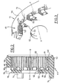
- La figure 1 est une vue en section axiale partielle du moteur électrique d'un démarreur associé à son train épicycloïdal comportant un dispositif limiteur de couple réalisé conformément aux enseignements de l'invention ;
- la figure 2 est une vue en section axiale et à plus grande échelle de la couronne dentée du réducteur à engrenages du démarreur de la figure 1 ; et
- la figure 3 est une vue en perspective de la couronne dentée de la figure 2.
- Figure 1 is a partial axial sectional view of the electric motor of a starter associated with its planetary gear comprising a torque limiting device produced in accordance with the teachings of the invention;
- Figure 2 is an axial section on a larger scale of the ring gear of the gear reducer of the starter of Figure 1; and
- FIG. 3 is a perspective view of the toothed ring of FIG. 2.
On a représenté sur la figure 1 une partie d'un
démarreur 10 de véhicule automobile du type comportant un
moteur électrique 12 dont le rotor 14 est monté tournant,
autour d'un axe X-X à l'intérieur d'une partie arrière 16 du
boítier du démarreur qui est complétée par une partie avant 18
en forme de capot.Part 1 of a
La partie supérieure (non illustrée en détails) du
démarreur 10 comporte un contacteur électromagnétique qui,
par l'intermédiaire d'un levier 20 en forme de fourche, agit de
manière connue sur un lanceur 22 qui est monté coulissant sur
un arbre de lanceur 24 coaxial à l'arbre de sortie 26 du moteur
électrique 12.The upper part (not shown in detail) of the
L'arbre de sortie 26 du moteur électrique 12, lié en
rotation au rotor 14, fait saillie axialement vers l'avant au delà
de la face avant 28 du stator 30 et il entraíne en rotation un
pignon 32 qui est le pignon solaire d'un train épicycloïdal 34
qui constitue un réducteur à engrenages interposé entre l'arbre
de sortie 26 et l'arbre de lanceur 24.The
Le pignon solaire 32 coopère avec les pignons
satellites 36 du train épicycloïdal 34 qui sont montés à rotation
autour d'axes 38 qui sont portés par un plateau radial 40
porte-satellites qui est lié en rotation à l'arbre de sortie 42 du
réducteur 34 qui est un arbre creux à l'intérieur duquel est
reçu l'extrémité cannelée arrière (non représentée) de l'arbre
de lanceur 24 pour l'entraínement en rotation de ce dernier par
l'arbre de sortie 42.The
Le train épicycloïdal 34 comporte aussi une couronne
44 dentée intérieurement à l'intérieur de laquelle engrènent les
satellites 36 et qui est immobilisée en rotation par rapport au
boítier du démarreur 10.The
La couronne dentée 44, réalisée conformément aux
enseignements de l'invention, est constituée pour l'essentiel
par une jupe annulaire cylindrique 46 qui est ouverte
axialement à son extrémité arrière 48 et dont l'extrémité avant
est fermée par une paroi radiale 50 qui est percée en son
centre d'un trou 52 dans lequel, est monté à rotation l'arbre de
sortie 42.The
La surface périphérique 56 de la jupe 46 est une
surface cylindrique et la couronne dentée 44 est reçue dans
une cavité cylindrique creuse complémentaire 58 formée dans
le capot 18 du boítier du démarreur 10 et qui est ouverte
axialement vers l'arrière pour permettre l'introduction axiale,
de la droite vers la gauche en considérant la figure 1, de la
couronne dentée 44 dans la cavité 58, cette dernière étant
délimitée axialement par un épaulement radial 60.The
La surface cylindrique interne de la jupe 46 est
dentée et elle comporte à cet effet une série de dents 62 qui
s'étendent sur toute la longueur axiale de la surface interne
dentée 61, c'est-à-dire notamment sensiblement jusqu'au fond
de la couronne dentée 44 constituée par la face radiale interne
64 de la paroi 50.The internal cylindrical surface of the
Conformément aux enseignements de l'invention, et
afin de constituer une zone 66 déformable élastiquement en
torsion, la portion d'extrémité axiale avant de la jupe 46
comporte une série d'évidements 70 répartis angulairement de
manière régulière autour de l'axe X-X de la couronne dentée
44.In accordance with the teachings of the invention, and
in order to constitute an elastically
Les évidements 70, qui traversent radialement de part
en part l'épaisseur du matériau constitutif de la jupe 46,
délimitent entre eux autant de bras de liaison 72 dont chacun
s'étend axialement pour relier la jupe 46 à la paroi radiale de
fond 50.The
L'ensemble des bras 72 constitue la zone 66
déformable élastiquement en torsion, c'est-à-dire que leur
déformation élastique permet, par fléchissement transversal
des bras 72, de faire globalement tourner la jupe 46 par
rapport à la paroi 50.The set of
La couronne dentée 44 est liée en rotation au boítier
10 par une série d'ergots 74, ici au nombre de trois, dont
chacun s'étend axialement vers l'avant à partir de la face
radiale externe 76 de la paroi 50.The
La face supérieure cylindrique 78 de chaque ergot 74
est dans le prolongement de la face cylindrique externe 56 de
la jupe 46 et chaque ergot 74 est reçu dans un logement
complémentaire formé dans l'épaulement de fond 60 de la
cavité 58.The cylindrical
Comme on peut le voir notamment sur la figure 2,
chaque évidement 70 s'étend axialement vers l'arrière dans la
paroi de fond 50 pour déboucher dans la face radiale avant 76
de cette dernière, l'évidement étant délimité radialement vers
l'intérieur par un bord intérieur 75.As we can see in particular in Figure 2,
each
Lorsque la couronne dentée 44 est en position dans
le capot 18 du boítier du démarreur comme cela est illustré à
la figure 1, elle est globalement immobilisée en rotation par les
ergots 74. When the
Toutefois, du fait de la présence de la zone
déformable 66, la jupe dentée 46 peut tourner par rapport à la
paroi 50 et donc par rapport au boítier.However, due to the presence of the area
deformable 66, the
Conformément à l'invention, le démarreur 10
comporte ainsi des moyens d'amortissement élastique en
torsion agencés au niveau du réducteur à engrenages 34 qui
ne font appel à aucun composant supplémentaire par rapport à
un démarreur équipé d'un train épicycloïdal classique, seule la
conception de la couronne dentée étant modifiée
conformément aux enseignements de l'invention.According to the invention, the
L'invention n'est pas limitée au cas d'un réducteur à
train épicycloïdal mais trouve aussi à s'appliquer dans d'autres
cas, par exemple lorsque le réducteur 34 est un train à
engrenages décalés comportant une couronne dentée
intérieurement.The invention is not limited to the case of a reduction gear with
planetary gear but also found to apply in other
case, for example when the
Claims (9)
- Motor vehicle starter (10) of the type comprising a casing (18) in which there is arranged an electric motor (12) whose output shaft (26) drives a coaxial starter head (22) with the interposing of a reduction gear (34) comprising an internally toothed ring (44), which is mounted in a cavity (58) in the casing in which it is immobilised in rotation and which comprises a cylindrical annular skirt (46) toothed internally and closed at one of its axial ends by a radial wall (50) pierced at its centre for the passage of an output shaft (42) of the reducing gear, the toothed ring (44) comprising a zone (66) which is elastically deformable under torsion and which is arranged at one of the axial ends of the internally toothed skirt (46) in order to act between the latter and an adjacent part of the ring comprising means (74) for the rotational immobilisation of the ring (44) in its cavity (58), characterised in that the elastically deformable zone consists of a series of elastically deformable connecting arms (72), substantially axial in orientation, which connect the axial end of the toothed skirt (46) to the adjacent part (50) of the toothed ring (44) comprising the means (74) of immobilising in rotation.
- Starter according to Claim 1, characterised in that the connecting arms (72) are angularly distributed in a regular manner around the axis (X-X) of the ring.
- Starter according to Claim 2, characterised in that two adjacent connecting arms (72) are separated by a recess (70) formed at least partly in the radial thickness of an axial end portion of the internally toothed skirt (46).
- Starter according to Claim 3, characterised in that the said recess passes radially through the axial end portion of the internally toothed skirt.
- Starter according to any one of the preceding claims, characterised in that the elastically deformable zone (66, 70, 72) is arranged at the axial end of the internally toothed skirt which is closed by the radial wall (50).
- Starter according to Claim 5 taken in combination with one of Claims 3 or 4, characterised in that the said recess (70) extends axially in the radial wall (50).
- Starter according to any one of the preceding claims, characterised in that the means for rotational immobilisation of the toothed ring in its cavity comprise at least one toe (74) carried by the ring (44) which is received in a complementary housing (60) in the casing.
- Starter according to Claim 7, characterised in that the toe (74) extends axially from the external face (76) of the radial partition (50) of the ring (44).
- Starter according to any one of the preceding claims, characterised in that the reducing gear (34) is of the epicyclic train type.
Applications Claiming Priority (2)
| Application Number | Priority Date | Filing Date | Title |
|---|---|---|---|
| FR9710310A FR2767157B1 (en) | 1997-08-11 | 1997-08-11 | STARTER OF A MOTOR VEHICLE WITH GEAR REDUCER COMPRISING AN IMPACT LIMITING DEVICE |
| FR9710310 | 1997-08-11 |
Publications (2)
| Publication Number | Publication Date |
|---|---|
| EP0921307A1 EP0921307A1 (en) | 1999-06-09 |
| EP0921307B1 true EP0921307B1 (en) | 2003-02-05 |
Family
ID=9510263
Family Applications (1)
| Application Number | Title | Priority Date | Filing Date |
|---|---|---|---|
| EP19980402013 Expired - Lifetime EP0921307B1 (en) | 1997-08-11 | 1998-08-06 | Starter for automotive vehicle with gear reductor comprising an impact limiting device |
Country Status (4)
| Country | Link |
|---|---|
| EP (1) | EP0921307B1 (en) |
| DE (1) | DE69811191T2 (en) |
| ES (1) | ES2192753T3 (en) |
| FR (1) | FR2767157B1 (en) |
Cited By (1)
| Publication number | Priority date | Publication date | Assignee | Title |
|---|---|---|---|---|
| DE102014200727A1 (en) | 2014-01-16 | 2015-07-16 | Schaeffler Technologies AG & Co. KG | Starting device for a vehicle and vehicle with the starter device |
Families Citing this family (7)
| Publication number | Priority date | Publication date | Assignee | Title |
|---|---|---|---|---|
| FR2796989B1 (en) * | 1999-07-30 | 2001-09-14 | Valeo Equip Electr Moteur | STARTER OF A MOTOR VEHICLE WITH A SIMPLIFIED OUTPUT SHAFT |
| EP1347171A1 (en) * | 2002-03-22 | 2003-09-24 | Valeo Mando Electrical Systems Korea Limited | Apparatus for absorbing impact of starter |
| DE10214278A1 (en) * | 2002-03-28 | 2003-10-16 | Bosch Gmbh Robert | starter |
| FR2863017B1 (en) | 2003-11-28 | 2007-12-21 | Valeo Equip Electr Moteur | MOTOR VEHICLE STARTER WITH REDUCER COMPRISING ARTICLES OF ARTICULATION OF THE CONTROL LEVER |
| FR2863016B1 (en) | 2003-11-28 | 2007-11-16 | Valeo Equip Electr Moteur | MOTOR VEHICLE STARTER EQUIPPED WITH REDUCER CENTERING AND CYLINDER HEADS ON THE HOUSING |
| FR2910074B1 (en) * | 2006-12-14 | 2009-01-23 | Valeo Equip Electr Moteur | STARTING DEVICE FOR A THERMAL MOTOR, IN PARTICULAR A MOTOR VEHICLE |
| DE102010003431B4 (en) * | 2010-03-30 | 2019-05-16 | Seg Automotive Germany Gmbh | Starting device with ring gear and intermediate bearing damping |
Family Cites Families (6)
| Publication number | Priority date | Publication date | Assignee | Title |
|---|---|---|---|---|
| EP0127880B1 (en) * | 1983-05-31 | 1988-01-07 | Hitachi, Ltd. | Reduction starter |
| JPS60111059A (en) * | 1983-11-18 | 1985-06-17 | Hitachi Ltd | Starter for internal-combustion engine |
| JPS61101668A (en) * | 1984-10-24 | 1986-05-20 | Hitachi Ltd | Starter equipped with planetary reduction gear |
| JPH0526309Y2 (en) * | 1986-02-24 | 1993-07-02 | ||
| JPH0571452A (en) * | 1991-09-11 | 1993-03-23 | Hitachi Ltd | Starter |
| JPH0678495A (en) * | 1992-07-09 | 1994-03-18 | Nippondenso Co Ltd | Impact torque absorber |
-
1997
- 1997-08-11 FR FR9710310A patent/FR2767157B1/en not_active Expired - Lifetime
-
1998
- 1998-08-06 DE DE1998611191 patent/DE69811191T2/en not_active Expired - Lifetime
- 1998-08-06 EP EP19980402013 patent/EP0921307B1/en not_active Expired - Lifetime
- 1998-08-06 ES ES98402013T patent/ES2192753T3/en not_active Expired - Lifetime
Cited By (2)
| Publication number | Priority date | Publication date | Assignee | Title |
|---|---|---|---|---|
| DE102014200727A1 (en) | 2014-01-16 | 2015-07-16 | Schaeffler Technologies AG & Co. KG | Starting device for a vehicle and vehicle with the starter device |
| DE102014200727B4 (en) * | 2014-01-16 | 2016-11-17 | Schaeffler Technologies AG & Co. KG | Starting device for a vehicle and vehicle with the starter device |
Also Published As
| Publication number | Publication date |
|---|---|
| EP0921307A1 (en) | 1999-06-09 |
| FR2767157A1 (en) | 1999-02-12 |
| FR2767157B1 (en) | 1999-09-10 |
| DE69811191D1 (en) | 2003-03-13 |
| DE69811191T2 (en) | 2003-09-11 |
| ES2192753T3 (en) | 2003-10-16 |
Similar Documents
| Publication | Publication Date | Title |
|---|---|---|
| EP1058786B1 (en) | Motor vehicle starter with reduction gear comprising means forming torsional damper | |
| FR2803345A1 (en) | STARTER EQUIPPED WITH DAMPER DEVICE AND TORQUE LIMITING DEVICE | |
| EP0924425A1 (en) | Starter for automotive vehicle comprising an improved pinion | |
| EP0921307B1 (en) | Starter for automotive vehicle with gear reductor comprising an impact limiting device | |
| FR2566868A1 (en) | Epicyclic reduction gear for IC engine starter motor | |
| EP0854284B1 (en) | Starter for motor vehicule with epicyclic reduction gear having a torque limiter | |
| EP0685045A1 (en) | Torsional damper having a sealed ring-shaped housing, in particular for motor vehicles | |
| EP0715696B1 (en) | Damping flywheel for a motor vehicle power unit | |
| FR2546998A1 (en) | CONES CLUTCH, IN PARTICULAR FOR A ROTATION INVERSION BOX, FOR MOTOR BOATS | |
| FR2609132A1 (en) | Damping flywheel for transmission, particularly for a motor vehicle | |
| FR2660037A1 (en) | DOUBLE SHOCK ABSORBER, IN PARTICULAR FOR A MOTOR VEHICLE. | |
| FR2618199A1 (en) | TORSION SHOCK ABSORBER. | |
| FR2754856A1 (en) | Starter motor clutch for motor vehicle internal combustion engine | |
| FR2613015A1 (en) | Device for an additional gear ratio in a mechanical gear box | |
| FR2498392A1 (en) | IMPROVEMENTS TO ELECTRIC STARTERS FOR INTERNAL COMBUSTION ENGINES COMPRISING A REDUCER INSERTED BETWEEN ITS ELECTRIC MOTOR AND ITS LAUNCHER | |
| FR2576985A1 (en) | Bearing to be interposed radially between two rotating parts, especially for clutches for motor vehicles and method for mounting such a bearing | |
| EP3044455A1 (en) | Starter drive assembly for an electric starter comprising a manoeuvring ring rigidly connected to a pinion | |
| FR2830574A1 (en) | STARTER, PARTICULARLY FOR AN ENGINE OF A MOTOR VEHICLE OF THE COUPLING LAUNCHER TYPE | |
| FR2754855A1 (en) | Electronic vehicle starter motor with lever-controlled drive pinion | |
| FR2878908A1 (en) | IC engine starting device for e.g. motor vehicle, has epicycloidal speed reducing gear train that comprises rotation axles connected to pulley, and planet gears mounted in freely rotating manner on pulley constituting planet carriers | |
| EP0919742B1 (en) | Torsional damper and friction unit for such a damper. | |
| FR2714440A1 (en) | Vehicle torsion absorbing device | |
| FR3033612A1 (en) | COMPACT MULTI-WHEEL DOUBLE CLUTCH TRANSMISSION FOR A GEARBOX OF A MOTOR VEHICLE | |
| FR2754857A1 (en) | Torsion-damped automobile engine starter without free-wheel | |
| FR2623588A1 (en) | Epicycloid speed reduction set particularly for heat engine starters |
Legal Events
| Date | Code | Title | Description |
|---|---|---|---|
| PUAI | Public reference made under article 153(3) epc to a published international application that has entered the european phase |
Free format text: ORIGINAL CODE: 0009012 |
|
| AK | Designated contracting states |
Kind code of ref document: A1 Designated state(s): DE ES GB IT |
|
| AX | Request for extension of the european patent |
Free format text: AL;LT;LV;MK;RO;SI |
|
| 17P | Request for examination filed |
Effective date: 19990818 |
|
| AKX | Designation fees paid |
Free format text: DE ES GB IT |
|
| GRAG | Despatch of communication of intention to grant |
Free format text: ORIGINAL CODE: EPIDOS AGRA |
|
| 17Q | First examination report despatched |
Effective date: 20020410 |
|
| GRAG | Despatch of communication of intention to grant |
Free format text: ORIGINAL CODE: EPIDOS AGRA |
|
| GRAH | Despatch of communication of intention to grant a patent |
Free format text: ORIGINAL CODE: EPIDOS IGRA |
|
| GRAH | Despatch of communication of intention to grant a patent |
Free format text: ORIGINAL CODE: EPIDOS IGRA |
|
| GRAA | (expected) grant |
Free format text: ORIGINAL CODE: 0009210 |
|
| AK | Designated contracting states |
Designated state(s): DE ES GB IT |
|
| REG | Reference to a national code |
Ref country code: GB Ref legal event code: FG4D Free format text: NOT ENGLISH |
|
| REF | Corresponds to: |
Ref document number: 69811191 Country of ref document: DE Date of ref document: 20030313 Kind code of ref document: P |
|
| GBT | Gb: translation of ep patent filed (gb section 77(6)(a)/1977) |
Effective date: 20030326 |
|
| PGFP | Annual fee paid to national office [announced via postgrant information from national office to epo] |
Ref country code: GB Payment date: 20030729 Year of fee payment: 6 |
|
| PGFP | Annual fee paid to national office [announced via postgrant information from national office to epo] |
Ref country code: ES Payment date: 20030806 Year of fee payment: 6 |
|
| REG | Reference to a national code |
Ref country code: ES Ref legal event code: FG2A Ref document number: 2192753 Country of ref document: ES Kind code of ref document: T3 |
|
| PLBE | No opposition filed within time limit |
Free format text: ORIGINAL CODE: 0009261 |
|
| STAA | Information on the status of an ep patent application or granted ep patent |
Free format text: STATUS: NO OPPOSITION FILED WITHIN TIME LIMIT |
|
| 26N | No opposition filed |
Effective date: 20031106 |
|
| PG25 | Lapsed in a contracting state [announced via postgrant information from national office to epo] |
Ref country code: GB Free format text: LAPSE BECAUSE OF NON-PAYMENT OF DUE FEES Effective date: 20040806 |
|
| PG25 | Lapsed in a contracting state [announced via postgrant information from national office to epo] |
Ref country code: ES Free format text: LAPSE BECAUSE OF NON-PAYMENT OF DUE FEES Effective date: 20040807 |
|
| GBPC | Gb: european patent ceased through non-payment of renewal fee |
Effective date: 20040806 |
|
| REG | Reference to a national code |
Ref country code: ES Ref legal event code: FD2A Effective date: 20040807 |
|
| PGFP | Annual fee paid to national office [announced via postgrant information from national office to epo] |
Ref country code: DE Payment date: 20150807 Year of fee payment: 18 |
|
| REG | Reference to a national code |
Ref country code: DE Ref legal event code: R119 Ref document number: 69811191 Country of ref document: DE |
|
| PG25 | Lapsed in a contracting state [announced via postgrant information from national office to epo] |
Ref country code: DE Free format text: LAPSE BECAUSE OF NON-PAYMENT OF DUE FEES Effective date: 20170301 |
|
| PGFP | Annual fee paid to national office [announced via postgrant information from national office to epo] |
Ref country code: IT Payment date: 20170809 Year of fee payment: 20 |