EP1069273B1 - Toilettentür - Google Patents
Toilettentür Download PDFInfo
- Publication number
- EP1069273B1 EP1069273B1 EP00114299A EP00114299A EP1069273B1 EP 1069273 B1 EP1069273 B1 EP 1069273B1 EP 00114299 A EP00114299 A EP 00114299A EP 00114299 A EP00114299 A EP 00114299A EP 1069273 B1 EP1069273 B1 EP 1069273B1
- Authority
- EP
- European Patent Office
- Prior art keywords
- door
- frame
- vent louver
- mounting portion
- vent
- Prior art date
- Legal status (The legal status is an assumption and is not a legal conclusion. Google has not performed a legal analysis and makes no representation as to the accuracy of the status listed.)
- Expired - Lifetime
Links
Images


Classifications
-
- E—FIXED CONSTRUCTIONS
- E06—DOORS, WINDOWS, SHUTTERS, OR ROLLER BLINDS IN GENERAL; LADDERS
- E06B—FIXED OR MOVABLE CLOSURES FOR OPENINGS IN BUILDINGS, VEHICLES, FENCES OR LIKE ENCLOSURES IN GENERAL, e.g. DOORS, WINDOWS, BLINDS, GATES
- E06B7/00—Special arrangements or measures in connection with doors or windows
- E06B7/02—Special arrangements or measures in connection with doors or windows for providing ventilation, e.g. through double windows; Arrangement of ventilation roses
- E06B7/08—Louvre doors, windows or grilles
- E06B7/082—Louvre doors, windows or grilles with rigid or slidable lamellae
-
- E—FIXED CONSTRUCTIONS
- E06—DOORS, WINDOWS, SHUTTERS, OR ROLLER BLINDS IN GENERAL; LADDERS
- E06B—FIXED OR MOVABLE CLOSURES FOR OPENINGS IN BUILDINGS, VEHICLES, FENCES OR LIKE ENCLOSURES IN GENERAL, e.g. DOORS, WINDOWS, BLINDS, GATES
- E06B7/00—Special arrangements or measures in connection with doors or windows
- E06B7/02—Special arrangements or measures in connection with doors or windows for providing ventilation, e.g. through double windows; Arrangement of ventilation roses
-
- F—MECHANICAL ENGINEERING; LIGHTING; HEATING; WEAPONS; BLASTING
- F24—HEATING; RANGES; VENTILATING
- F24F—AIR-CONDITIONING; AIR-HUMIDIFICATION; VENTILATION; USE OF AIR CURRENTS FOR SCREENING
- F24F13/00—Details common to, or for air-conditioning, air-humidification, ventilation or use of air currents for screening
- F24F13/08—Air-flow control members, e.g. louvres, grilles, flaps or guide plates
- F24F13/082—Grilles, registers or guards
- F24F13/084—Grilles, registers or guards with mounting arrangements, e.g. snap fasteners for mounting to the wall or duct
Definitions
- the present invention relates to a door of a lavatory unit allowing users to access said lavatory unit.
- said door comprising a door body, an opening perforated to the lower portion of said door body. and a vent louver mounted to said opening via a frame of said door.
- said vent louver comprises a ventilation having a plurality of air holes a provided to the center portion of said vent louver.
- the GB-698 759 discloses an arrangement for supporting a ventilation grille inside an opening.
- the ventilation grille is provided with leaf springs on one side and rigid fingers on the opposite side of the grille. Both the leaf springs and the rigid fingers cooperate with a tooth profile on the inner surface of a frame carrying the grille.
- the grille is held inside the frame by means of the rigid fingers and the leaf springs which are also called resilient fingers by the document.
- the grille is shifted to the side of the leaf springs to compress the leaf springs until the rigid fingers may be taken out of the related teeth.
- the lavatory unit equipped inside a closed space, in an airplane for example, includes a vent louver mounted to its door, having air holes allowing air to flow into the lavatory unit.
- the vent louver is provided to the lower area of the door, and therefore, dusty air existing near the floor flows through continuously. Therefore, the vent louver was liable to collect dust.
- a door 11 allowing access of lavatory users is equipped to a lavatory unit 10.
- a vent louver 13 having air holes 15 is mounted to the lower portion of the door 11. Further, an exhaust port 17 connected to a vacuum mechanism is provided to a ceiling 12 of the lavatory unit 10. The air inside the cabin is taken into to the lavatory unit 10 by discharging the air inside the lavatory unit 10 through the exhaust port 17 as shown by arrow a, and air within the cabin is flown into the lavatory unit 10 through the air holes 15 of the vent louver 13 mounted to the door 11 by the intake of the air in the direction of arrow a.
- vent louver 13 is taken off from the door 10 and cleaned in order to evacuate the plugging of the air hole 15 of the vent louver.
- vent louver 13 is inserted to the disposition port of the door 11, and fixed at the bottom to the frame 11a of the door with a fastener 19. In order to dismount the vent louver 13 from the door 11, it is necessary to dismount the door 11 from the lavatory unit 10 and to take off the fastener 19 of the frame 11a.
- the present invention aims at providing a door of a lavatory unit which enables simple dismount of the vent louver. Thereby, the air inside the lavatory unit provided in a closed space is maintained clean, and the users feel more comfortable.
- the door is characterized by a mounting portion provided to the upper side of said ventilation for mounting said vent louver to said door body, and a mounting portion provided to the lower side of said ventilation for mounting said vent louver to said door body via said frame, said frame having a substantially U-shaped cross-section.
- said upper mounting portion of said vent louver being fixed to said door body with a fastener. said fastener being removable.
- said lower mounting portion of said vent louver comprising a connector connected to the outer wall of said frame, and an elastic connector inserted into said frame and flexibly connected to the inner wall of said frame. such that the lower portion of said vent louver grips said frame with said connector and said elastic connector.
- said vent louver being able to rotate in the direction perpendicular to said door surface centering on said elastic connector of said lower mounting portion, when said upper mounting portion is in an opened condition.
- the door according to the present invention of the lavatory unit allowing users to access said lavatory unit is equipped with a vent louver mounted to an opening perforated on the lower portion of a door body via a frame of the door.
- the vent louver comprises a ventilation having a plurality of air holes provided to the central portion thereof, a mounting portion fixed with fasteners to the door body provided to the upper portion of the ventilation, and a mounting portion for mounting the lower portion of the ventilation to the door body via the door frame.
- the mounting portion on the lower portion of the vent louver comprises a connector connected to the outer wall of the frame, and an elastic connector inserted to the frame and flexibly connected to the inner wall of the frame.
- the lower portion of the vent louver grips the frame with the connector and the elastic connector.
- the elastic connector of the lower mounting portion is provided with a leaf spring which is biased toward the inner wall direction of the frame when the lower mounting portion is inserted and provided in the frame.
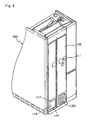
- FIG. 4 is a perspective view of the fundamental section of a lavatory unit 100 equipped with a door of the present invention.
- a latch 111 allowing a user to lock the door.
- a plurality of openings for mounting plural vent louvers 130.
- two vent louvers are provided thereto.
- the drawing shows the state where one vent louver is taken off (mounting hole 113) for explanation.
- a fastening hole 117 for mounting the vent louver 130 is perforated.
- the vent louver 130 has a ventilation 131 having a ventilation structure and provided to the center of the vent louver, an upper mounting portion 133 provided continuously at the upper part of the ventilation 131, and a lower mounting portion 135 provided continuously at the lower part of the ventilation 131.
- the ventilation 131 is comprised of two boards, each provided with a plurality of air holes 131a opened downwardly.
- the upper mounting portion 133 is made by superposing two plates, and a mounting hole 133a for mounting the fastener is opened to both ends thereof.
- the upper mounting portion 133 is mounted by matching the mounting hole 133a to the fastening hole 117 of the fitting hole 133 of the door body 110.
- the lower mounting portion 135 has an elastic connector 135S at the center thereof, and having at both sides thereof a connector 135F for being connected to the door frame and having a substantially L-shaped cross section.
- the elastic connector 135S of the lower mounting portion 135 is provided with a leaf spring 1350 and a support plate 1355 for the leaf spring 1350 having a substantially Z-shaped cross section.
- the leaf spring 1350 is mounted to the lower mounting portion 135, with one end of the leaf spring 1350 being fixed to one side of the support plate 1355, and the other ends being free ends.
- vent louver 130 having the above-mentioned structure is mounted to the fitting hole 113 of the door body 110 (FIG. 3).
- the lower mounting portion 135 of the vent louver 130 is equipped to the opening side of the frame 115 of the door body 110 having a substantially U-shaped cross section.
- One side of L-shaped connector 135F is connected to the frame 115, and the elastic connector 135S is inserted via the opening of the frame 115 so as to flexibly pressurize the leaf spring 1350 to the inner wall of the frame 115.
- the leaf spring 1350 is biased toward the direction of the inner wall of the frame 115, when being inserted inside the frame 115.
- the upper mounting portion 133 is mounted to the upper portion of the fitting hole 113 of the door, and the vent louver 130 is equipped to the door body 110 by fixing the fastener 140 via the fastening hole 117 of the door body and the hole 133a for the fastener of the vent louver 130.
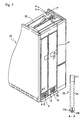
- the fastener 140 of the upper mounting portion 135 is removed, and the upper mounting portion 133 of the vent louver 130 is rotated about in the direction of arrow O shown in FIG. 2. Both ends of the lower mounting portion 135 of the vent louver are easily removed, since only one side of the L-shaped connector 135F is connected at the frame 115.
- the leaf spring 1350 rotates about centering on the contact point with the inner wall of the frame 115, accompanying the rotation of the vent louver 130. At this point, the leaf spring 1350 is pressed opposing to the bias force, and is removed from the frame 115.
- vent louver 130 of the present invention could be mounted to and dismounted from the door body 110 with ease, in which the door body 110 is equipped to the lavatory unit 110, by fastening and removing two fasteners 140 according to the present embodiment.
- the removed vent louver 130 could be cleaned with air or water at a cleaning facility, and therefore, it is possible to clean the vent louver 130 with ease during everyday maintenance.
- the door of a lavatory unit enables to mount and dismount the vent louver with the door being fixed to the unit, and therefore, the cleaning task is simplified.
Landscapes
- Engineering & Computer Science (AREA)
- Civil Engineering (AREA)
- Structural Engineering (AREA)
- Specific Sealing Or Ventilating Devices For Doors And Windows (AREA)
- Toilet Supplies (AREA)
- Residential Or Office Buildings (AREA)
- Ventilation (AREA)
- Sanitary Device For Flush Toilet (AREA)
Claims (2)
- Tür einer Toiletteneinheit (100), die den Eintritt eines Benutzers zu der Toiletteneinheit gestattet, welche Tür einen Türkorpus (110), eine Öffnung (113) im unteren Bereich des Türkorpus (110) und ein Belüftungsgitter (130), das in der Öffnung mithilfe eines Rahmens (115) der Tür montiert ist, umfaßt,
wobei das Lüftungsgitter (130) eine Belüftung (131) mit einer Anzahl von Luftlöchern (131a) im Mittelbereich des Belüftungsgitters umfaßt,
gekennzeichnet durch einen Montagebereich (133), der an der oberen Seite der Belüftung (131) vorgesehen ist für die Montage des Belüftungsgitters (130) an dem Türkorpus (110), und einem Montagebereich (135) an der unteren Seite der Belüftung (131) für die Montage des Belüftungsgitters (130) an dem Türkorpus mithilfe des Rahmens (115), welcher Rahmen einen im wesentlichen U-förmigen Querschnitt aufweist,
wobei der obere Montagebereich (133) des Belüftungsgitters (130) an dem Türkorpus (110) mithilfe eines Befestigers (140) angebracht ist, welcher Befestiger entfernbar ist,
wobei der untere Montagebereich (135) des Belüftungsgitters einen Verbinder (135F), der mit der äußeren Wand des Rahmens (115) verbunden ist, und einen elastischen Verbinder (135S) umfaßt, der in den Rahmen eingefügt und elastisch verbunden mit der inneren Wand des Rahmens (115) ist, derart, daß der untere Bereich des Belüftungsgitters (130) den Rahmen (115) mit dem Verbinder (135F) und dem elastischen Verbinder (135S) erfaßt,
wobei das Belüftungsgitter (130) in Richtung senkrecht zur Türoberfläche drehbar ist mit einem Mittelpunkt an dem elastischen Verbinder (135S) des unteren Verbindungsbereiches, wenn der obere Verbindungsbereich (133) in der offenen Stellung steht. - Tür einer Toiletteneinheit gemäß Anspruch 1, bei der eine Blattfeder, die in Richtung der inneren Wand des Rahmens (115) vorgespannt ist, wenn das Belüftungsgitter (130) in den Rahmen eingefügt und hier fixiert ist, an dem elastischen Verbinder des unteren Verbindungsbereichs des Belüftungsgitters (130) vorgesehen ist.
Applications Claiming Priority (3)
| Application Number | Priority Date | Filing Date | Title |
|---|---|---|---|
| JP530599 | 1999-07-15 | ||
| JP53059999U | 1999-07-15 | ||
| JP1999005305U JP3065815U (ja) | 1999-07-15 | 1999-07-15 | ラバトリ―ユニットのドア |
Publications (3)
| Publication Number | Publication Date |
|---|---|
| EP1069273A2 EP1069273A2 (de) | 2001-01-17 |
| EP1069273A3 EP1069273A3 (de) | 2002-11-06 |
| EP1069273B1 true EP1069273B1 (de) | 2004-02-25 |
Family
ID=11607573
Family Applications (1)
| Application Number | Title | Priority Date | Filing Date |
|---|---|---|---|
| EP00114299A Expired - Lifetime EP1069273B1 (de) | 1999-07-15 | 2000-07-04 | Toilettentür |
Country Status (4)
| Country | Link |
|---|---|
| US (1) | US6336293B1 (de) |
| EP (1) | EP1069273B1 (de) |
| JP (1) | JP3065815U (de) |
| DE (1) | DE60008459T2 (de) |
Families Citing this family (16)
| Publication number | Priority date | Publication date | Assignee | Title |
|---|---|---|---|---|
| CA2424380A1 (en) * | 2001-09-16 | 2003-03-27 | Mul-T-Lock Security Products Ltd. | Access apparatus |
| US6698690B2 (en) * | 2002-02-28 | 2004-03-02 | Alcoa Inc. | Impact resistant door containing resealable panels |
| US6702230B2 (en) | 2002-06-04 | 2004-03-09 | The Boeing Company | Ballistic resistant flight deck door assembly having ventilation feature |
| US20070277458A1 (en) * | 2006-05-22 | 2007-12-06 | Graboyes Steven M | Fireproof louvered closures such as doors and windows, and methods for providing the same |
| US8651924B1 (en) * | 2010-05-06 | 2014-02-18 | The Boeing Company | Interlocking vent assembly for equalizing pressure in a compartment |
| CN101858194B (zh) * | 2010-05-25 | 2012-10-24 | 邱康红 | Led气囊气垫式居室门 |
| CN101858191B (zh) * | 2010-05-25 | 2012-05-30 | 邱康红 | 气囊气垫式居室门 |
| JP5418425B2 (ja) * | 2010-07-01 | 2014-02-19 | コベルコ建機株式会社 | キャビンのドア |
| CN101967944B (zh) * | 2010-10-18 | 2012-05-30 | 邱康红 | 防护板气囊居室门 |
| US8460419B1 (en) | 2012-03-15 | 2013-06-11 | Cliff Hobbs | Airplane lavatory filtering system device |
| EP2745880B1 (de) * | 2012-12-18 | 2020-02-19 | Airbus Operations GmbH | Tür mit einem Profilstreifen als Brandanzeigevorrichtung in einem Flugzeug |
| CN104499911B (zh) * | 2014-12-01 | 2016-06-08 | 国家电网公司 | 百叶窗 |
| US10156086B2 (en) * | 2015-05-15 | 2018-12-18 | Mike Wayne Hart | Dual entry safety cuff port |
| CN106014142A (zh) * | 2016-06-24 | 2016-10-12 | 桐城市丽琼金属制品有限公司 | 一种透气防盗门 |
| CN110685565B (zh) * | 2019-10-12 | 2021-02-02 | 谷奕舡 | 一种改进型防火卷帘门 |
| EP4729414A1 (de) * | 2024-10-18 | 2026-04-22 | Airbus Operations, S.L.U. | Belüftungssystem für flugzeuge und flugzeug mit besagtem belüftungssystem |
Family Cites Families (11)
| Publication number | Priority date | Publication date | Assignee | Title |
|---|---|---|---|---|
| US1958342A (en) * | 1930-07-22 | 1934-05-08 | Johnson Metal Products Co | Window ventilator |
| GB553423A (en) * | 1942-03-20 | 1943-05-20 | Ralph Alexander Whitson | Improvements in or relating to ventilators |
| US2398914A (en) * | 1944-05-15 | 1946-04-23 | Insulated Windows Inc | Window ventilator |
| BE503202A (de) * | 1950-05-11 | |||
| US2778417A (en) * | 1955-02-21 | 1957-01-22 | Novitz Gleason | Animal exit |
| FR1167245A (fr) * | 1957-02-26 | 1958-11-21 | Plaque d'aération | |
| DE2450331A1 (de) * | 1974-10-23 | 1976-05-06 | Messerschmitt Boelkow Blohm | Transportable toilettenzelle |
| NL7613834A (en) * | 1976-12-13 | 1978-06-15 | Reynolds Aluminium Bv | Profile frame for window or roof - has aluminium sections with edge flanges to retain panel, external and internal rubber or foam sealing strips |
| US4644687A (en) * | 1985-07-22 | 1987-02-24 | Liou Shu L | Door with a shutter device |
| JP3280756B2 (ja) * | 1993-06-23 | 2002-05-13 | 株式会社ジャムコ | 航空機用中折れドア |
| US5716270A (en) * | 1996-10-16 | 1998-02-10 | Chambers; Charles F. | Frictionally mounted louvered diffuser |
-
1999
- 1999-07-15 JP JP1999005305U patent/JP3065815U/ja not_active Expired - Lifetime
-
2000
- 2000-07-04 DE DE60008459T patent/DE60008459T2/de not_active Expired - Fee Related
- 2000-07-04 EP EP00114299A patent/EP1069273B1/de not_active Expired - Lifetime
- 2000-07-12 US US09/614,457 patent/US6336293B1/en not_active Expired - Fee Related
Also Published As
| Publication number | Publication date |
|---|---|
| DE60008459D1 (de) | 2004-04-01 |
| EP1069273A2 (de) | 2001-01-17 |
| US6336293B1 (en) | 2002-01-08 |
| EP1069273A3 (de) | 2002-11-06 |
| DE60008459T2 (de) | 2004-11-25 |
| JP3065815U (ja) | 2000-02-08 |
Similar Documents
| Publication | Publication Date | Title |
|---|---|---|
| EP1069273B1 (de) | Toilettentür | |
| GB2384972A (en) | Air exhaust structure for an upright-type vacuum cleaner | |
| EP2083224B1 (de) | Deckenklimaanlage mit Filterreinigungsmechanismus | |
| KR100436142B1 (ko) | 공기조화기의 실내기 | |
| US4801316A (en) | Molded fiberglass air return filter grille | |
| JP3606784B2 (ja) | 空気調和機の室内機 | |
| JP3043141B2 (ja) | 空気調和機 | |
| JP2000081238A (ja) | 化粧パネル取付装置 | |
| JP3306898B2 (ja) | 空気調和機 | |
| CN100383466C (zh) | 空调器 | |
| JPH1163597A (ja) | 換気扇用フィルタ | |
| JP3970733B2 (ja) | 換気装置 | |
| JPH0444977Y2 (de) | ||
| KR100457563B1 (ko) | 공기조화기 | |
| JP2532362Y2 (ja) | 空気調和機 | |
| GB2411346A (en) | Air discharge structure for a vacuum cleaner | |
| JP3039751B2 (ja) | 空気調和機 | |
| JP2755608B2 (ja) | エアフィルタの取付装置 | |
| JP3426725B2 (ja) | 換気扇用フィルタ−カバ− | |
| JPH07305889A (ja) | 空気調和装置のエアフィルタ配置構造 | |
| JPH0894135A (ja) | 換気扇用フィルタ−カバ− | |
| JP2000130042A (ja) | 換気装置 | |
| JPH11157331A (ja) | 空気吹出吸込口の構造 | |
| JPH02166333A (ja) | 換気装置 | |
| KR100526804B1 (ko) | 버스의 에어컨 리턴덕트 장착구조 |
Legal Events
| Date | Code | Title | Description |
|---|---|---|---|
| PUAI | Public reference made under article 153(3) epc to a published international application that has entered the european phase |
Free format text: ORIGINAL CODE: 0009012 |
|
| AK | Designated contracting states |
Kind code of ref document: A2 Designated state(s): AT BE CH CY DE DK ES FI FR GB GR IE IT LI LU MC NL PT SE |
|
| AX | Request for extension of the european patent |
Free format text: AL;LT;LV;MK;RO;SI |
|
| PUAL | Search report despatched |
Free format text: ORIGINAL CODE: 0009013 |
|
| AK | Designated contracting states |
Kind code of ref document: A3 Designated state(s): AT BE CH CY DE DK ES FI FR GB GR IE IT LI LU MC NL PT SE |
|
| AX | Request for extension of the european patent |
Free format text: AL;LT;LV;MK;RO;SI |
|
| 17P | Request for examination filed |
Effective date: 20021211 |
|
| 17Q | First examination report despatched |
Effective date: 20030203 |
|
| GRAP | Despatch of communication of intention to grant a patent |
Free format text: ORIGINAL CODE: EPIDOSNIGR1 |
|
| AKX | Designation fees paid |
Designated state(s): DE FR GB NL |
|
| GRAS | Grant fee paid |
Free format text: ORIGINAL CODE: EPIDOSNIGR3 |
|
| GRAA | (expected) grant |
Free format text: ORIGINAL CODE: 0009210 |
|
| AK | Designated contracting states |
Kind code of ref document: B1 Designated state(s): DE FR GB NL |
|
| REG | Reference to a national code |
Ref country code: GB Ref legal event code: FG4D |
|
| REG | Reference to a national code |
Ref country code: IE Ref legal event code: FG4D |
|
| REF | Corresponds to: |
Ref document number: 60008459 Country of ref document: DE Date of ref document: 20040401 Kind code of ref document: P |
|
| ET | Fr: translation filed | ||
| PLBE | No opposition filed within time limit |
Free format text: ORIGINAL CODE: 0009261 |
|
| STAA | Information on the status of an ep patent application or granted ep patent |
Free format text: STATUS: NO OPPOSITION FILED WITHIN TIME LIMIT |
|
| 26N | No opposition filed |
Effective date: 20041126 |
|
| REG | Reference to a national code |
Ref country code: IE Ref legal event code: MM4A |
|
| PGFP | Annual fee paid to national office [announced via postgrant information from national office to epo] |
Ref country code: DE Payment date: 20080731 Year of fee payment: 9 |
|
| PGFP | Annual fee paid to national office [announced via postgrant information from national office to epo] |
Ref country code: FR Payment date: 20080627 Year of fee payment: 9 Ref country code: NL Payment date: 20080731 Year of fee payment: 9 |
|
| PGFP | Annual fee paid to national office [announced via postgrant information from national office to epo] |
Ref country code: GB Payment date: 20080711 Year of fee payment: 9 |
|
| GBPC | Gb: european patent ceased through non-payment of renewal fee |
Effective date: 20090704 |
|
| NLV4 | Nl: lapsed or anulled due to non-payment of the annual fee |
Effective date: 20100201 |
|
| REG | Reference to a national code |
Ref country code: FR Ref legal event code: ST Effective date: 20100331 |
|
| PG25 | Lapsed in a contracting state [announced via postgrant information from national office to epo] |
Ref country code: FR Free format text: LAPSE BECAUSE OF NON-PAYMENT OF DUE FEES Effective date: 20090731 |
|
| PG25 | Lapsed in a contracting state [announced via postgrant information from national office to epo] |
Ref country code: GB Free format text: LAPSE BECAUSE OF NON-PAYMENT OF DUE FEES Effective date: 20090704 |
|
| PG25 | Lapsed in a contracting state [announced via postgrant information from national office to epo] |
Ref country code: DE Free format text: LAPSE BECAUSE OF NON-PAYMENT OF DUE FEES Effective date: 20100202 |
|
| PG25 | Lapsed in a contracting state [announced via postgrant information from national office to epo] |
Ref country code: NL Free format text: LAPSE BECAUSE OF NON-PAYMENT OF DUE FEES Effective date: 20100201 |