EP1053883B1 - Ink jet recording apparatus - Google Patents
Ink jet recording apparatus Download PDFInfo
- Publication number
- EP1053883B1 EP1053883B1 EP00104790A EP00104790A EP1053883B1 EP 1053883 B1 EP1053883 B1 EP 1053883B1 EP 00104790 A EP00104790 A EP 00104790A EP 00104790 A EP00104790 A EP 00104790A EP 1053883 B1 EP1053883 B1 EP 1053883B1
- Authority
- EP
- European Patent Office
- Prior art keywords
- recording medium
- recording
- ink jet
- jet recording
- ribs
- Prior art date
- Legal status (The legal status is an assumption and is not a legal conclusion. Google has not performed a legal analysis and makes no representation as to the accuracy of the status listed.)
- Expired - Lifetime
Links
Images


Classifications
-
- B—PERFORMING OPERATIONS; TRANSPORTING
- B41—PRINTING; LINING MACHINES; TYPEWRITERS; STAMPS
- B41J—TYPEWRITERS; SELECTIVE PRINTING MECHANISMS, i.e. MECHANISMS PRINTING OTHERWISE THAN FROM A FORME; CORRECTION OF TYPOGRAPHICAL ERRORS
- B41J11/00—Devices or arrangements of selective printing mechanisms, e.g. ink-jet printers or thermal printers, for supporting or handling copy material in sheet or web form
- B41J11/0045—Guides for printing material
- B41J11/005—Guides in the printing zone, e.g. guides for preventing contact of conveyed sheets with printhead
-
- B—PERFORMING OPERATIONS; TRANSPORTING
- B41—PRINTING; LINING MACHINES; TYPEWRITERS; STAMPS
- B41J—TYPEWRITERS; SELECTIVE PRINTING MECHANISMS, i.e. MECHANISMS PRINTING OTHERWISE THAN FROM A FORME; CORRECTION OF TYPOGRAPHICAL ERRORS
- B41J11/00—Devices or arrangements of selective printing mechanisms, e.g. ink-jet printers or thermal printers, for supporting or handling copy material in sheet or web form
- B41J11/02—Platens
- B41J11/06—Flat page-size platens or smaller flat platens having a greater size than line-size platens
-
- B—PERFORMING OPERATIONS; TRANSPORTING
- B41—PRINTING; LINING MACHINES; TYPEWRITERS; STAMPS
- B41J—TYPEWRITERS; SELECTIVE PRINTING MECHANISMS, i.e. MECHANISMS PRINTING OTHERWISE THAN FROM A FORME; CORRECTION OF TYPOGRAPHICAL ERRORS
- B41J13/00—Devices or arrangements of selective printing mechanisms, e.g. ink-jet printers or thermal printers, specially adapted for supporting or handling copy material in short lengths, e.g. sheets
- B41J13/02—Rollers
-
- B—PERFORMING OPERATIONS; TRANSPORTING
- B41—PRINTING; LINING MACHINES; TYPEWRITERS; STAMPS
- B41J—TYPEWRITERS; SELECTIVE PRINTING MECHANISMS, i.e. MECHANISMS PRINTING OTHERWISE THAN FROM A FORME; CORRECTION OF TYPOGRAPHICAL ERRORS
- B41J13/00—Devices or arrangements of selective printing mechanisms, e.g. ink-jet printers or thermal printers, specially adapted for supporting or handling copy material in short lengths, e.g. sheets
- B41J13/10—Sheet holders, retainers, movable guides, or stationary guides
- B41J13/14—Aprons or guides for the printing section
Definitions
- the present invention relates to an ink jet recording apparatus according to the preamble of claim 1.
- the shorter the flying passage of ink the higher becomes the accuracy in which the adhesive positions of ink are secured.
- a recording apparatus of the kind it is required to set the gap between the recording surface of a recording medium and the recording head (hereinafter referred to as a "head gap") as narrow as possible.
- the head gap is made narrower, a rubbing of the kind as described above tends to occur more often.
- a structure (a first conventional example) is disclosed in the specifications of JP-A-61-95966 and 3-29359 that a plurality of small holes are provided for the platen or suction force is allowed to act upon a recording medium through small holes by use of negative pressure generating means, thus the recording medium being held closely in contact with the platen.
- JP-A-4-69264 a mechanism (a second conventional example) is disclosed in order to press a recording medium by use of a paper pressure member arranged on the upstream side in the carrying direction of the recording medium.
- an ink jet recording apparatus (a third conventional example) in which a plurality of ribs, which are extended on the flat platen in the carrying direction of a recording medium, are arranged in the direction intersecting the carrying direction of the recording medium, and then, on the upstream side of the ribs, the pressure plate is arranged to be extended in the direction intersecting the carrying direction of the recording medium in order to nip it together with each tip of the ribs. Also, for this ink jet recording apparatus, the extrusions are arranged on the respective positions of the pressure plate corresponding to each of the gaps between ribs, thus exerting the force that presses the recording medium downward.
- the recording medium is not sufficiently pressed closely to the platen if the recording area is wide.
- the recording medium is pressed by the paper pressure member to the platen on the upstream side, while being nipped by the sheet exhaust roller or the like on the downstream side.
- the recording medium is not pressed at all on the recording area or the like which exists between these sides.
- the recording area is wide so that one line portion of the recording head should become wider, there is a fear that the recording medium is caused to float from the platen or the cockling takes place on the recording medium on the recording area only with the depression exerted by the paper pressure member on the upstream side and by the exhaust rollers on the downstream side.
- the paper pressure plate is arranged without any exception on the position that is substantially in contact with each leading end of the ribs on the upstream side thereof.
- the ribs which are set on the lower face of the paper pressure plate arranged in the gap between each of the ribs adjacent to each other on the upstream, cannot prevent the floating of a recording medium from the platen completely in a case where a comparatively robust recording medium, such as cardboard, is carried or recording is performed on a wide recording area, although there is an effect that the recording medium is pressed in the direction of the platen when the recording medium is placed in a position between ribs.
- US-5 700 099A discloses a generic ink jet recording apparatus for recording with deposition of ink droplets to a recording medium by use of ink jet recording means, comprising a platen provided on a position facing said ink jet recording means; a plurality of pinching portions comprised by rollers for nipping and carrying said recording medium to the position of ink deposition to said recording medium using said ink jet recording means; and extrusions provided on a surface of said platen opposed to said recording head and being arranged in a plurality in the direction intersecting the carrying direction of said recording medium to support the reverse side of said recording medium, wherein said pinching portions are positioned with respect to said extrusions on the upstream side in the carrying direction of said recording medium.
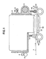
- Fig. 1 is a cross-sectional view which shows the circumference of the recording area of a recording apparatus in accordance with a first embodiment of the present invention.
- Fig. 2 is a perspective view which schematically shows the circumference thereof.
- the recording apparatus of the present embodiment is provided with the recording head 1 of ink jet recording type that records images or the like with the deposition of ink droplets discharged to a recording medium.
- the recording head 1 is detachably mounted on a carriage 2.
- the carriage 2 is slidably supported on a guide rail 3, and the guide roller 4 which is protruded from the carriage 2 is rotatively supported on a supporting rail 5.
- the carriage 2 scans along the guide rail 3 and the supporting rail 5.
- ink droplets are discharged from the recording head 1 mounted on the carriage 2 to the specific positions on a recording medium 7 for recording images or the like on it.
- the carrying mechanism for the recording medium 7 will be described.
- a pair of carrier rollers 10 comprising the upstream side carrier roller 8 which is driven by a motor (not shown) and the driven roller 9 which is pressed to the upstream side carrier roller 8 by means of a biasing spring 11 to rotate following the rotation thereof.
- the rotational center of the driven roller 9 is placed in a position slightly deviated to the downstream side in the carrying direction than the rotational center of the upstream side carrier roller 8. Therefore, the carrier roller pair 10 send out the recording medium 7 diagonally downward, while pressing it to the platen 19.
- the driven roller 9 functions as a pressure roller that presses the recording medium 7 to the platen 19.
- each of the driven rollers 9 is individually biased by means of the biasing spring 11, it becomes possible to press the recording medium 7 appropriately in accordance with the amount of deformation of each portion thereof.
- the platen 19 is arranged to face the recording head 1. Then, on the guiding surface for the recording medium 7, a plurality of extrusive ribs 17, each extruded in the carrying direction, are arranged in line in the direction intersecting the carrying direction. A plurality of driven rollers 9 are arranged corresponding to these ribs 17, and the central position of the driven rollers 9 in the direction of the rotational axis, and the central position of the ribs 17 are arranged to be on one and the same line in the carrying direction.
- the sheet exhaust roller pairs 14 which comprise the downstream side carrier rollers 12 driven by a motor (not shown), and the spurs 13 serving as the rotational devices used for sheet exhaust which are biased by means of basing spring 15 to rotate following the rotation of the downstream side rollers 12.
- Each of the spurs 13 has a small contact area with the recording medium 7 so that recorded images are not spoiled even when the spurs are in contact with the recording surface thereof after recording.
- Each of the sheet exhaust roller pairs 14 is provided with a nipping portion to nip the recording medium 7, and the portion which is not in contact with the recording medium (non-nipping portion) alternately in the direction intersecting the carrying direction of the recording medium.
- these portions are positioned to arrange the nipping portions and the vertices of the ribs 17 to be on one and same straight line in the carrying direction.
- the nipping portions are positioned without any exception.
- the recording medium 7 is carried to the nipping portion of the carrier roller pair 10. Then, by the rotation of the carrier roller pair 10, the recording medium is carried on the platen 19 to the recording position that faces the recording head 1.
- the recording head 1 is guided to the recording position by the scanning of the carriage 2 where the recording operation is carried out for the deposition of ink onto the recording medium 7.
- the carrier roller pair 10 carries the recording sheet 7 at specific pitches. Then, when the recording medium 7 reaches the sheet exhaust roller pair 14 by means of sheet feeding, the sheet is carried by the cooperation of the sheet exhaust roller pair 14 and the carrier roller pair 10. After the trailing end of the recording medium 7 leaves the carrier roller pair 10, the sheet is carried only by the sheet exhaust roller pair 14. When the recording operation is completed, the sheet exhaust roller pair 14 sends out the recording medium 7 onto the exhausted sheet tray which is not shown.
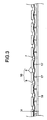
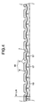
- Fig. 3 and Fig. 4 are views observed in the direction indicated by an arrow A in Fig. 1.
- Fig. 3 shows the state of the ordinary paper sheet before recording.
- Fig. 4 shows the state where cockling occurs on the ordinary paper sheet after recording.
- the recording medium 7 is carried, while being pressed by the driven rollers 9 from diagonally above to the platen 19.
- the pressure exerted by the driven rollers 9 is not absorbed only by the upstream side carrier rollers 8.
- the pressure also acts upon in the direction in which the recording medium 7 is pressed to the platen 19.
- the recording medium 7 which abuts against the platen 19 diagonally is caused to bend between the contact surfaces of the carrier roller pairs 10 and the platen 19.
- the biasing force is exerted to press the recording medium 7 to the platen 19.
- This biasing force is obtainable most effectively by arranging the center of each rib 17 and that of the rotational position of the driven rollers 9 in the rotational direction thereof on one and same straight line in the carrying direction of the recording medium 7.
- the substantially equal biasing force may be obtainable at least by arranging each of the driven rollers 9, which corresponds to the width of the driven roller 9, in the area of each rib 17 on the upstream of the carrying direction of the recording medium 7 without exception.
- the recording medium 7 thus pressed to the platen 19 abuts against the ribs 17 to be bent and recessed between ribs 17. Then, as shown in Fig. 3, the recording medium is deformed to present moderate corrugation with the contacted surface with ribs 17 as the vertices thereof.
- the recording ink whose main solvent is water adheres to the recording medium 7 by use of the recording head 1 the recording medium 7 swells by the absorption of water to bring about the occurrence of cockling.
- the sheet floating does not easily take place due to the pressure exerted thereon.
- the waving amount X of the recording medium 7 before recording changes into the waving amount X + ⁇ X after recording.
- the recording medium 7 tends to create the wavy deformation in the direction perpendicular to the carrying direction thereof, but the deformation is not easily caused in the carrying direction.
- the deformation caused by the swelling of the recording medium 7 is absorbed by the increased amount of the wavy deformation directed toward the platen 19 side.
- the contact between the recording medium 7 and the recording head 1 is controlled so as to suppress the occurrence of the unfavorable influence to the recorded images.
- each of the sheet exhaust roller pairs 14 is structured to nip only the vertices of the wavy deformation of the recording medium 7, that is, to nip only the portions positioned at the vertices of the ribs 17.
- the sheet floating can be suppressed due to the fact that the recording medium 7 is no longer pressed by the sheet exhaust roller pairs 14 to the platen 17.
- the recording head 1 it becomes possible to narrow the gap between the recording head 1 and the platen 19 (head gap), because the sheet floating can be suppressed.
- the distance of the flight of discharged ink is made smaller by narrowing the head gap, hence providing a high quality recording apparatus which presents highly precise positions of ink deposition.
- each of the carrier roller pairs 10 is formed by the upstream side carrier rollers 8, and the driven roller unit 9' which is provided with a plurality of irregular shapes in the direction of axial rotation. Then, the arrangement is made so as to position the ribs 17, and almost the central location of extruded portions of the driven roller unit 9' in the direction of the axial rotation to be on one and the same straight line in the carrying direction. Then, particularly, on each extended line of ribs 17 on the upstream in the carrying direction, the nipping portion, which formed by each driven roller 9 and carrier roller 8, is positioned without exception.
- the driven roller unit 9' each having a plurality of the same driven rollers 9 as the first embodiment, which are connected by the shaft 20, respectively, it becomes possible to reduce the number of parts, such as the roller supporting mechanism, the biasing spring, and form a simpler structure to reduce the costs of manufacture accordingly.
- three driven rollers 9 are connected by the shaft 20 each to form the driven roller unit 9', respectively.
- a recording medium is corrugated during the recording operation, and pressed to the platen, so as to absorb, with the increased amount of such corrugation, the cockling that may be created by the swelling of the recording medium by the absorption of ink, hence suppressing the sheet floating.
- the recording medium which is deformed to present corrugation is not easily deformed in the carrying direction thereof, the trailing end of the recording medium does not float easily even if the recording medium is pressed to the platen by the sheet exhaust roller pairs. With the suppression of the sheet floating, it is possible to narrow the gap between the recording surface of the recording medium and recording means to implement recording in higher quality.
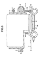
- Fig. 6 is a cross-sectional view which shows the circumference of the recording area thereof.
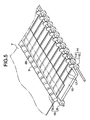
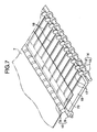
- Fig. 7 is a perspective view which schematically shows it.
- the platen 19 is arranged in the facing position of the recording head 1 to guide and support a recording medium 7.
- a plurality of ribs 17 and 18 are arranged as extrusions extended in the carrying direction of the recording medium 7, which are formed respectively on the extended lines on the downstream side of a plurality of nipping portions of the carrier roller unit 10.
- the ribs 17 and the ribs 18 are different in the lengths thereof.
- the shorter ribs 18 originate from the points set more on the downstream side in the carrying direction as compared with the longer ribs 17, respectively.
- the sheet exhaust roller unit 14 formed by sheet exhaust rollers 12 and spurs 13 which are pressed by biasing springs 15 to the sheet exhaust rollers 12 to rotate following the rotation thereof, respectively, is arranged to exhaust the recording medium 7 to a sheet exhaust tray (not shown) after the passage of the recording area.
- the spur 13 is formed not to disturb the recorded images on the recording medium when it is in contact with the recording surface thereof after recording.
- the nipping portions of the sheet exhaust roller unit 14 are arranged almost downstream side of the extended lines of the ribs 17 and 18, and the carrier roller unit 10. Particularly, on the extended lines on the upstream in the carrying direction of the ribs 17 and 18, the nipping portions of the carrier roller unit 10 are arranged without exception.
- a recording medium 7 is carried to the nipping portion between the carrier roller 8 and the driven toller 9 of each carrier roller unit 10. Then, after inclination and others are corrected, the recording medium 7 is carried by the rotation of the carrier roller 8 and the driven roller 9 of each carrier roller unit 10 to the recording area of the recording head 1.
- the transfer of the recording medium 7 is once suspended.
- the carriage 2 scans along the guide rail 3 and the supporting rail 5.
- the one-line portion recording is performed by discharging ink droplets from the recording head 1 mounted on the carriage 2 to specific positions on the recording medium.
- the recording medium 7 is carried by one line portion by use of the carrier roller unit 10.
- the transfer of the recording medium 7 is suspended again, and the one-line portion scanning of the carriage 2 and recording by the recording 1 are performed. In this manner, the recording medium 7 is carried and recording by the recording head 1 are conducted alternately to record on the entire recording surface of the recording medium 7.
- the recording medium 7 is carried by the rotation of each sheet exhaust roller 12 and spur 13 of the sheet exhaust roller unit 14 in addition to the rotation of each carrier roller 8 and driven roller 9 of the carrier roller unit 10. Further, when the trailing end of the recording medium 7 leaves each carrier roller 8 and driven roller 9 of the carrier roller unit 10, the recording medium 7 is carried only by the rotation of each sheet exhaust roller 12 and spur 13 of the sheet exhaust roller unit 14.
- the recording medium 7 is exhausted after recording by the sheet exhaust roller unit 14 to the sheet exhaust tray which is not shown.
- the ordinary paper sheet 7 is placed along the ribs 17, and at the same time, it forms the recessed form by the biasing force exerted between the ribs 17, hence providing the moderately corrugated shape as indicated by two-dot chain line at 70 in Fig. 7.
- each portion which is corrugated between ribs 17 (the leading end of the ordinary paper sheet 7) abuts against each of the ribs 18 to be pushed upward. Then, as shown in Fig. 9, the corrugated shape is formed with the ribs 17 and 18 as the vertices thereof.
- each originating point of the ribs 18 is positioned more on the down stream than each originating point of the ribs 17 in the carrying direction. Therefore, the pressure, which is exerted by the carrier roller unit 10 to press the ordinary paper sheet (recording medium) 7 in the direction toward the platen 19, can be kept longer more to the downstream side (the amount of corrugation at this time is indicated by X in Fig. 9).
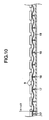
- the recording ink whose main solvent is water adheres to the ordinary paper sheet 7 by use of the recording head 1 the ordinary paper sheet 7 swells by the absorption of water to bring about the occurrence of cockling as shown in Fig. 10.
- the ribs 17 and 18 are arranged on the extended lines on the downstream side of the driven rollers 9, the portions nipped by the carrier roller unit 10 securely are pressed to the ribs 17 and 18. As a result, even if a greater deformation is made by swelling, most of such deformation is absorbed by the increased amount of bending to the platen side between ribs 17 and 18.
- the ordinary paper sheet 7 is recessed in the form of corrugation in advance between the ribs 17 and 18 on the platen 19, and the pressure, which is exerted by the carrier roller unit 10 to press the ordinary paper sheet 7 to the ribs 17 and 18, is maintained after the occurrence of swelling.
- the cockling takes place downward as shown in Fig. 10 to enable the recording sheet 7 to form between the ribs 17 and 18 the recessed portion of the corrugated amount indicated by (X + ⁇ X) in Fig. 10, respectively, hence making it possible to prevent the recording sheet from floating to the recording head 1 side.
- the ordinary paper sheet 7 having the cockling which has taken place in the recording area is carried to the sheet exhaust tray which is not shown by use of the sheet exhaust roller unit 14.
- the sheet exhaust roller unit 14 is arranged substantially on the one and same straight lines in the carrying direction along the ribs 17 and 18, there is no possibility that the moderate corrugation formed for the sheet in the recording area and the irregularities provided therefor by cockling are allowed to change.
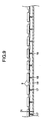
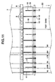
- the size of the recording medium (recording sheet) to be used is usually predetermined to a certain extent.
- the general printer or the like uses either one of recording media, such as postcard, B5, A4, LTR (letter size), B4, LDR (leisure size), and A3.
- the ribs 17 and 18 are positioned to be placed inside 1 mm to 10 mm of the side end portions of a recording medium depending on each size of the recording medium to be used. More specifically, as shown in Fig. 11, the standard position 50 is defined for carrying each medium. Then, it is arranged to align one edge portion of a recording medium 7 with this standard portion 50 for carrying the medium.
- the ribs 17 and 18 are arranged inside approximately 1 mm to 10 mm of the predetermined position of the other edge portion of the recording medium 7 of each size. For the portions other than those predetermined ones, a plurality of ribs 17 or 18 are arranged so that these ribs are set regularly to a certain extent.
- the carrier roller unit 10 and the sheet exhaust roller unit 14 are arranged substantially on the extended lines of all the ribs 17 or ribs 18 in the carrying direction.
- a recording medium 7 is carried with the side ends thereof placed along the ribs 17 or ribs 18, and further, carried while being nipped by the sheet exhaust roller unit 14 on the downstream side. As a result, it becomes possible to prevent the recording sheet 7 from floating to the recording head 1 side more reliably on the side end portions thereof.
- Fig. 12 is a cross-sectional view which shows the circumference of the recording area of a recording apparatus.
- the same reference marks are applied to the structures which are the same as those appearing in the third embodiment. Then, the description thereof will be omitted.
- each spur 21 is arranged to be in the position where the rotational center thereof is deviated more upstream of each rotational center of the sheet exhaust rollers 22 in the carrying direction.
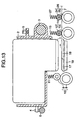
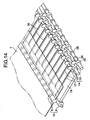
- Fig. 13 is a cross-sectional view which shows the circumference of the recording area of a recording apparatus.
- Fig. 14 is a schematic perspective view thereof.
- the same reference marks are applied to the structures which are the same as those appearing in the third embodiment. Therefore, the description thereof will be omitted.
- two sheet exhaust roller units 14 and 26 are provided for the present embodiment.
- the sheet exhaust roller unit 14 which is formed by the sheet exhaust roller 12 and the spur 13 which is pressed to the sheet exhaust roller 12 by use of the biasing spring 15 to rotate following the rotation thereof.
- the second row sheet exhaust roller unit 26 which is formed by the second row sheet exhaust roller 25 and the second row spur 24 pressed to the second row sheet exhaust roller 25 by use of the basing spring 27.
- the second row spurs 24 and second row sheet exhaust rollers 25 of the second row sheet exhaust roller unit 26 are the same as those of the sheet exhaust roller unit 14, and are arranged on one and the same straight lines of the ribs 17 and 18 in the carrying direction of the recording medium 7. As a result, there is no possibility that the moderate corrugation formed in the recording area, and the irregularities produced by cockling are allowed to change.
- the sheet exhaust roller units are arranged in two rows, it becomes possible to minimize the motion of the trailing end (the portion still resides in the recording area) of the recording medium 7 to float from the platen side to the recording head side by reaction even when the leading end of the recording media 7, which is exhausted (that is, the portion that has already left each nipping position of the sheet exhaust roller unit), is in a state where the leading portion thereof hangs downward by the weight thereof, that is, it is in the so-called bowing condition. In this manner, it is possible to prevent the recording medium 7 from floating to the recording head 1 side.
- the spurs may be in the positions where each rotational center of the spurs is deviated from each rotational center of the carrier rollers more in the upstream in the carrying direction.
- the recording medium 7 is pressed to the ribs 17 and 18, hence preventing it from floating to the recording head 1 side more reliably.
- the two kinds of ribs having different lengths are provided, and the originating points thereof are changed alternately and arranged on the upstream side of the respective carrying directions.
- the pressure is increased to press a recording medium on the ribs whose originating points are on the downstream side to make the preventive effect against the sheet floating more reliable.
- the recording medium is corrugated in advance, such as having extrusions on the portions where the recording medium is in contact with ribs, and recesses on the portions where it is placed between ribs.
- the cockling that may occur on the recording medium is absorbed by the increased amount of deformation of the recessed portions, hence making it rare for cockling to cause the recording sheet to float.
- the structure is arranged so that with the establishment of the standard position for carrying a medium to align one edge portion of a recording medium to be used for a recording apparatus, the ribs are provided inside the other edge portion thereof by 1 mm to 10 mm, hence suppressing the edge portions from floating. Further, by positioning the nipping portions of the downstream side sheet exhaust roller unit on the extended lines of ribs, the floating suppression becomes more reliable.
- the sheet exhaust roller unit being arranged in two rows, it becomes possible to suppress the motion of the trailing end of a recording medium to float by reaction even when the leading end of the recording medium hangs down.
- the floating of a recording medium from the platen can be suppressed to make the gap between the recording medium and recording means narrower, hence making it possible to perform a high quality recording.
- An ink jet recording apparatus which records with deposition of ink droplets to a recording medium by use of ink jet recording means, comprises a platen for supporting a recording medium in a position facing ink jet recording means, a plurality of carrier roller pairs for nipping and carrying the recording medium to the position of ink deposition the recording medium using the ink jet recording means and extrusions extended in the carrying direction of the recording medium with respect to the platen, at the same time, being arranged in a plurality in the direction intersecting the carrying direction of the recording medium to support the reverse side of recording medium.
- the carrier roller pairs are positioned on each of the extended lines of the extrusions on the upstream side of the carrying direction of the recording medium.
Applications Claiming Priority (6)
| Application Number | Priority Date | Filing Date | Title |
|---|---|---|---|
| JP13420799 | 1999-05-14 | ||
| JP13420599 | 1999-05-14 | ||
| JP13420599 | 1999-05-14 | ||
| JP13420799 | 1999-05-14 | ||
| JP2000051579A JP4194205B2 (ja) | 1999-05-14 | 2000-02-28 | インクジェット記録装置 |
| JP2000051579 | 2000-02-28 |
Publications (3)
| Publication Number | Publication Date |
|---|---|
| EP1053883A2 EP1053883A2 (en) | 2000-11-22 |
| EP1053883A3 EP1053883A3 (en) | 2000-11-29 |
| EP1053883B1 true EP1053883B1 (en) | 2004-10-20 |
Family
ID=27316847
Family Applications (1)
| Application Number | Title | Priority Date | Filing Date |
|---|---|---|---|
| EP00104790A Expired - Lifetime EP1053883B1 (en) | 1999-05-14 | 2000-03-06 | Ink jet recording apparatus |
Country Status (4)
| Country | Link |
|---|---|
| US (1) | US6659603B2 (ja) |
| EP (1) | EP1053883B1 (ja) |
| JP (1) | JP4194205B2 (ja) |
| DE (1) | DE60015009T2 (ja) |
Families Citing this family (44)
| Publication number | Priority date | Publication date | Assignee | Title |
|---|---|---|---|---|
| US6971811B2 (en) * | 2002-07-25 | 2005-12-06 | Silverbrook Research Pty Ltd | Print engine having a pair of feed rollers and a print zone proximal thereto |
| US20020144770A1 (en) * | 2001-04-06 | 2002-10-10 | Stephane Mabit | Carrier-less patch protection including cassette and separation process |
| US6869176B2 (en) * | 2001-09-07 | 2005-03-22 | Canon Kabushiki Kaisha | Recording apparatus, and recording medium floating prevention member |
| US6712463B2 (en) * | 2001-09-07 | 2004-03-30 | Canon Kabushiki Kaisha | Recording apparatus |
| JP2003292224A (ja) | 2002-01-31 | 2003-10-15 | Seiko Epson Corp | インクジェット式記録装置及び排紙装置 |
| JP4073008B2 (ja) | 2002-09-17 | 2008-04-09 | キヤノン株式会社 | 記録装置 |
| KR100472479B1 (ko) * | 2002-10-31 | 2005-03-08 | 삼성전자주식회사 | 잉크젯 프린터의 용지 가이드 및 그를 구비한 잉크젯 프린터 |
| JP2004203526A (ja) * | 2002-12-24 | 2004-07-22 | Sharp Corp | 記録装置 |
| JP4013909B2 (ja) * | 2003-04-10 | 2007-11-28 | セイコーエプソン株式会社 | 液体噴射装置 |
| JP3694006B2 (ja) * | 2003-05-21 | 2005-09-14 | シャープ株式会社 | インクジェットプリンタ |
| JP2005047227A (ja) * | 2003-07-31 | 2005-02-24 | Canon Inc | 両面記録装置 |
| JP4719409B2 (ja) * | 2003-08-29 | 2011-07-06 | キヤノン株式会社 | 記録方法 |
| JP2005082373A (ja) * | 2003-09-10 | 2005-03-31 | Sharp Corp | インクジェットプリンタ |
| TW200540018A (en) * | 2004-06-09 | 2005-12-16 | Benq Corp | Print system with upgrading print quality |
| JP2006103278A (ja) * | 2004-10-08 | 2006-04-20 | Canon Inc | 記録装置 |
| US7673985B2 (en) * | 2005-05-25 | 2010-03-09 | Brother Kogyo Kabushiki Kaisha | Ink-jet recording apparatus provided with platen and movable support section for supporting recording paper |
| US7811016B2 (en) * | 2005-05-25 | 2010-10-12 | Agfa Graphics Nv | Flatbed printing machine |
| EP1803574B1 (en) * | 2005-12-27 | 2012-09-19 | Brother Kogyo Kabushiki Kaisha | Inkjet recording device and driving unit provided therein |
| US8157368B2 (en) | 2006-01-31 | 2012-04-17 | Brother Kogyo Kabushiki Kaisha | Ink jet recording device and method of conveying recording medium in the same |
| JP5194671B2 (ja) * | 2007-09-25 | 2013-05-08 | セイコーエプソン株式会社 | 記録装置 |
| JP2009256098A (ja) * | 2008-03-19 | 2009-11-05 | Seiko Epson Corp | 流体噴射装置 |
| JP2010143123A (ja) * | 2008-12-19 | 2010-07-01 | Canon Inc | 記録装置および記録方法 |
| JP2010149478A (ja) * | 2008-12-26 | 2010-07-08 | Seiko Epson Corp | 記録媒体、及び記録装置 |
| JP5293325B2 (ja) * | 2009-03-25 | 2013-09-18 | セイコーエプソン株式会社 | 記録装置及び搬送方法 |
| JP5338424B2 (ja) * | 2009-03-25 | 2013-11-13 | セイコーエプソン株式会社 | 記録装置及び搬送方法 |
| JP4873084B2 (ja) * | 2010-01-25 | 2012-02-08 | ブラザー工業株式会社 | インクジェット記録装置 |
| EP2571697B1 (en) * | 2010-05-17 | 2016-11-16 | Memjet Technology Limited | System for distributing fluid and gas within printer |
| CN102407684B (zh) * | 2010-09-10 | 2014-07-30 | 精工爱普生株式会社 | 纸输送装置及印刷装置 |
| JP5287830B2 (ja) * | 2010-10-29 | 2013-09-11 | ブラザー工業株式会社 | インクジェット記録装置 |
| JP5700205B2 (ja) * | 2011-02-08 | 2015-04-15 | セイコーエプソン株式会社 | 記録装置 |
| JP2012254608A (ja) * | 2011-06-10 | 2012-12-27 | Mimaki Engineering Co Ltd | 媒体処理装置 |
| JP5942570B2 (ja) | 2011-11-28 | 2016-06-29 | ブラザー工業株式会社 | インクジェット記録装置 |
| US8967796B2 (en) | 2011-11-28 | 2015-03-03 | Brother Kogyo Kabushiki Kaisha | Inkjet recording apparatus |
| JP5924221B2 (ja) * | 2012-09-28 | 2016-05-25 | ブラザー工業株式会社 | 搬送装置及びインクジェット記録装置 |
| US9045299B2 (en) * | 2013-02-18 | 2015-06-02 | Lexmark International, Inc. | Star wheel with adjustable directional biaser |
| JP2014162631A (ja) * | 2013-02-27 | 2014-09-08 | Katsuragawa Electric Co Ltd | 媒体の排出機構 |
| JP5705291B2 (ja) * | 2013-11-08 | 2015-04-22 | キヤノン株式会社 | 記録装置 |
| JP6547482B2 (ja) | 2015-07-21 | 2019-07-24 | セイコーエプソン株式会社 | 液体吐出装置 |
| JPWO2017130302A1 (ja) * | 2016-01-26 | 2018-05-24 | 富士通フロンテック株式会社 | 紙葉類搬送機構及び紙葉類取扱装置 |
| JP6919341B2 (ja) * | 2017-05-31 | 2021-08-18 | セイコーエプソン株式会社 | 記録装置 |
| JP7094680B2 (ja) * | 2017-09-29 | 2022-07-04 | キヤノン株式会社 | 画像形成装置 |
| JP6515165B2 (ja) * | 2017-10-13 | 2019-05-15 | シャープ株式会社 | 用紙搬送装置およびそれを備える画像形成装置 |
| JP6735874B2 (ja) * | 2019-04-15 | 2020-08-05 | シャープ株式会社 | 用紙搬送装置およびそれを備える画像形成装置 |
| JP7202974B2 (ja) | 2019-06-03 | 2023-01-12 | 東日本旅客鉄道株式会社 | 防音パネル固定器具及び防音パネル固定方法 |
Family Cites Families (19)
| Publication number | Priority date | Publication date | Assignee | Title |
|---|---|---|---|---|
| JPS6195966A (ja) | 1984-10-18 | 1986-05-14 | Nec Corp | 印字用紙浮き防止機構 |
| JPH0469264A (ja) | 1990-07-10 | 1992-03-04 | Nec Data Terminal Ltd | インクジェットプリンタの用紙押え機構 |
| US5326011A (en) * | 1993-01-22 | 1994-07-05 | Printware, Inc. | Reduced-skew web drive between rollers of differing coefficients of friction, particularly to transport paper, metal or film in a laser imager |
| ATE209573T1 (de) | 1993-07-28 | 2001-12-15 | Canon Kk | Tintenstrahlaufzeichnungsgerät und tintenstrahlaufzeichnungsverfahren |
| JP2718626B2 (ja) | 1993-11-16 | 1998-02-25 | キヤノン株式会社 | シート材搬送装置 |
| SG46614A1 (en) | 1994-02-10 | 1998-02-20 | Seiko Epson Corp | Ink jet printer |
| JP3432052B2 (ja) | 1994-09-02 | 2003-07-28 | キヤノン株式会社 | インクジェット記録装置 |
| JP3376148B2 (ja) | 1995-02-21 | 2003-02-10 | キヤノン株式会社 | 画像読み取り機能を有する記録装置 |
| US5847719A (en) * | 1995-02-21 | 1998-12-08 | Canon Kabushiki Kaisha | Recording apparatus |
| JP3259592B2 (ja) | 1995-04-21 | 2002-02-25 | セイコーエプソン株式会社 | インクジェットプリンタ |
| US6027211A (en) * | 1995-07-14 | 2000-02-22 | Canon Kabushiki Kaisha | Sheet feeding apparatus and recording apparatus |
| JP3841315B2 (ja) | 1995-12-26 | 2006-11-01 | キヤノン株式会社 | プリント装置およびこの装置に用いられるプリント方法 |
| WO1997032729A1 (fr) * | 1996-03-04 | 1997-09-12 | Copyer Co., Ltd. | Dispositif de formation d'image |
| JPH1016350A (ja) * | 1996-03-14 | 1998-01-20 | Canon Inc | プリント装置 |
| JP3372800B2 (ja) * | 1996-12-06 | 2003-02-04 | キヤノン株式会社 | 記録装置 |
| US6089773A (en) | 1997-12-12 | 2000-07-18 | Lexmark International, Inc. | Print media feed system for an ink jet printer |
| US6113289A (en) * | 1998-01-05 | 2000-09-05 | Seiko Epson Corporation | Dot recording device |
| JP3762155B2 (ja) * | 1999-08-20 | 2006-04-05 | キヤノン株式会社 | 排紙装置及びこれを備えた画像形成装置 |
| JP4522015B2 (ja) * | 2001-05-10 | 2010-08-11 | キヤノン株式会社 | 記録装置 |
-
2000
- 2000-02-28 JP JP2000051579A patent/JP4194205B2/ja not_active Expired - Fee Related
- 2000-03-02 US US09/517,506 patent/US6659603B2/en not_active Expired - Fee Related
- 2000-03-06 EP EP00104790A patent/EP1053883B1/en not_active Expired - Lifetime
- 2000-03-06 DE DE60015009T patent/DE60015009T2/de not_active Expired - Lifetime
Also Published As
| Publication number | Publication date |
|---|---|
| EP1053883A3 (en) | 2000-11-29 |
| DE60015009T2 (de) | 2006-02-09 |
| JP4194205B2 (ja) | 2008-12-10 |
| US6659603B2 (en) | 2003-12-09 |
| JP2001031288A (ja) | 2001-02-06 |
| EP1053883A2 (en) | 2000-11-22 |
| DE60015009D1 (de) | 2004-11-25 |
| US20020171727A1 (en) | 2002-11-21 |
Similar Documents
| Publication | Publication Date | Title |
|---|---|---|
| EP1053883B1 (en) | Ink jet recording apparatus | |
| JP3432052B2 (ja) | インクジェット記録装置 | |
| JP3658159B2 (ja) | 記録装置 | |
| US6896432B2 (en) | Recording apparatus | |
| JP3594354B2 (ja) | プリンタ機構 | |
| KR0148618B1 (ko) | 잉크제트프린터 | |
| US5805176A (en) | Ink jet printer and device for insuring proper printing | |
| JP2000071532A (ja) | インクジェット記録装置 | |
| US6616361B2 (en) | Ink jet recording apparatus | |
| JP3762155B2 (ja) | 排紙装置及びこれを備えた画像形成装置 | |
| JP3507485B2 (ja) | インクジェット記録装置 | |
| JP3860651B2 (ja) | プリンタ機構 | |
| JP3770311B2 (ja) | ドット記録装置 | |
| CN100445186C (zh) | 记录装置 | |
| JP2001341886A (ja) | 記録装置 | |
| GB2290262A (en) | Paper handling in ink jet printer. | |
| JP3629869B2 (ja) | インクジェットプリンタ | |
| JP3329428B2 (ja) | インクジェットプリンタ | |
| JP2005271231A (ja) | インクジェット記録装置 | |
| JP3629870B2 (ja) | インクジェットプリンタ | |
| JP2994392B2 (ja) | 記録装置 | |
| JP3624924B2 (ja) | インクジェットプリンタの排紙装置 | |
| JP2006142777A (ja) | インクジェット記録装置 | |
| JP2010158844A (ja) | プリンタ | |
| JPH10244720A (ja) | 記録装置 |
Legal Events
| Date | Code | Title | Description |
|---|---|---|---|
| PUAI | Public reference made under article 153(3) epc to a published international application that has entered the european phase |
Free format text: ORIGINAL CODE: 0009012 |
|
| PUAL | Search report despatched |
Free format text: ORIGINAL CODE: 0009013 |
|
| AK | Designated contracting states |
Kind code of ref document: A2 Designated state(s): DE FR GB IT |
|
| AX | Request for extension of the european patent |
Free format text: AL;LT;LV;MK;RO;SI |
|
| AK | Designated contracting states |
Kind code of ref document: A3 Designated state(s): AT BE CH CY DE DK ES FI FR GB GR IE IT LI LU MC NL PT SE |
|
| AX | Request for extension of the european patent |
Free format text: AL;LT;LV;MK;RO;SI |
|
| 17P | Request for examination filed |
Effective date: 20010412 |
|
| AKX | Designation fees paid |
Free format text: DE FR GB IT |
|
| 17Q | First examination report despatched |
Effective date: 20020716 |
|
| GRAP | Despatch of communication of intention to grant a patent |
Free format text: ORIGINAL CODE: EPIDOSNIGR1 |
|
| GRAS | Grant fee paid |
Free format text: ORIGINAL CODE: EPIDOSNIGR3 |
|
| GRAA | (expected) grant |
Free format text: ORIGINAL CODE: 0009210 |
|
| AK | Designated contracting states |
Kind code of ref document: B1 Designated state(s): DE FR GB IT |
|
| REG | Reference to a national code |
Ref country code: GB Ref legal event code: FG4D |
|
| REF | Corresponds to: |
Ref document number: 60015009 Country of ref document: DE Date of ref document: 20041125 Kind code of ref document: P |
|
| PLBE | No opposition filed within time limit |
Free format text: ORIGINAL CODE: 0009261 |
|
| STAA | Information on the status of an ep patent application or granted ep patent |
Free format text: STATUS: NO OPPOSITION FILED WITHIN TIME LIMIT |
|
| ET | Fr: translation filed | ||
| 26N | No opposition filed |
Effective date: 20050721 |
|
| PGFP | Annual fee paid to national office [announced via postgrant information from national office to epo] |
Ref country code: IT Payment date: 20090306 Year of fee payment: 10 |
|
| PGFP | Annual fee paid to national office [announced via postgrant information from national office to epo] |
Ref country code: FR Payment date: 20090325 Year of fee payment: 10 |
|
| REG | Reference to a national code |
Ref country code: FR Ref legal event code: ST Effective date: 20101130 |
|
| PG25 | Lapsed in a contracting state [announced via postgrant information from national office to epo] |
Ref country code: FR Free format text: LAPSE BECAUSE OF NON-PAYMENT OF DUE FEES Effective date: 20100331 |
|
| PG25 | Lapsed in a contracting state [announced via postgrant information from national office to epo] |
Ref country code: IT Free format text: LAPSE BECAUSE OF NON-PAYMENT OF DUE FEES Effective date: 20100306 |
|
| PGFP | Annual fee paid to national office [announced via postgrant information from national office to epo] |
Ref country code: GB Payment date: 20150316 Year of fee payment: 16 |
|
| PGFP | Annual fee paid to national office [announced via postgrant information from national office to epo] |
Ref country code: DE Payment date: 20150331 Year of fee payment: 16 |
|
| REG | Reference to a national code |
Ref country code: DE Ref legal event code: R119 Ref document number: 60015009 Country of ref document: DE |
|
| GBPC | Gb: european patent ceased through non-payment of renewal fee |
Effective date: 20160306 |
|
| PG25 | Lapsed in a contracting state [announced via postgrant information from national office to epo] |
Ref country code: DE Free format text: LAPSE BECAUSE OF NON-PAYMENT OF DUE FEES Effective date: 20161001 Ref country code: GB Free format text: LAPSE BECAUSE OF NON-PAYMENT OF DUE FEES Effective date: 20160306 |