EP1044855B1 - Airbagvorrichtung - Google Patents
Airbagvorrichtung Download PDFInfo
- Publication number
- EP1044855B1 EP1044855B1 EP00107889A EP00107889A EP1044855B1 EP 1044855 B1 EP1044855 B1 EP 1044855B1 EP 00107889 A EP00107889 A EP 00107889A EP 00107889 A EP00107889 A EP 00107889A EP 1044855 B1 EP1044855 B1 EP 1044855B1
- Authority
- EP
- European Patent Office
- Prior art keywords
- air bag
- bag body
- vehicle occupant
- inner air
- outer air
- Prior art date
- Legal status (The legal status is an assumption and is not a legal conclusion. Google has not performed a legal analysis and makes no representation as to the accuracy of the status listed.)
- Expired - Lifetime
Links
Images


Classifications
-
- B—PERFORMING OPERATIONS; TRANSPORTING
- B60—VEHICLES IN GENERAL
- B60R—VEHICLES, VEHICLE FITTINGS, OR VEHICLE PARTS, NOT OTHERWISE PROVIDED FOR
- B60R21/00—Arrangements or fittings on vehicles for protecting or preventing injuries to occupants or pedestrians in case of accidents or other traffic risks
- B60R21/02—Occupant safety arrangements or fittings, e.g. crash pads
- B60R21/16—Inflatable occupant restraints or confinements designed to inflate upon impact or impending impact, e.g. air bags
- B60R21/23—Inflatable members
- B60R21/231—Inflatable members characterised by their shape, construction or spatial configuration
- B60R21/233—Inflatable members characterised by their shape, construction or spatial configuration comprising a plurality of individual compartments; comprising two or more bag-like members, one within the other
-
- B—PERFORMING OPERATIONS; TRANSPORTING
- B60—VEHICLES IN GENERAL
- B60R—VEHICLES, VEHICLE FITTINGS, OR VEHICLE PARTS, NOT OTHERWISE PROVIDED FOR
- B60R21/00—Arrangements or fittings on vehicles for protecting or preventing injuries to occupants or pedestrians in case of accidents or other traffic risks
- B60R21/02—Occupant safety arrangements or fittings, e.g. crash pads
- B60R21/16—Inflatable occupant restraints or confinements designed to inflate upon impact or impending impact, e.g. air bags
- B60R21/23—Inflatable members
- B60R21/239—Inflatable members characterised by their venting means
-
- B—PERFORMING OPERATIONS; TRANSPORTING
- B60—VEHICLES IN GENERAL
- B60R—VEHICLES, VEHICLE FITTINGS, OR VEHICLE PARTS, NOT OTHERWISE PROVIDED FOR
- B60R21/00—Arrangements or fittings on vehicles for protecting or preventing injuries to occupants or pedestrians in case of accidents or other traffic risks
- B60R21/02—Occupant safety arrangements or fittings, e.g. crash pads
- B60R21/16—Inflatable occupant restraints or confinements designed to inflate upon impact or impending impact, e.g. air bags
- B60R21/23—Inflatable members
- B60R21/231—Inflatable members characterised by their shape, construction or spatial configuration
- B60R21/233—Inflatable members characterised by their shape, construction or spatial configuration comprising a plurality of individual compartments; comprising two or more bag-like members, one within the other
- B60R2021/23324—Inner walls crating separate compartments, e.g. communicating with vents
-
- B—PERFORMING OPERATIONS; TRANSPORTING
- B60—VEHICLES IN GENERAL
- B60R—VEHICLES, VEHICLE FITTINGS, OR VEHICLE PARTS, NOT OTHERWISE PROVIDED FOR
- B60R21/00—Arrangements or fittings on vehicles for protecting or preventing injuries to occupants or pedestrians in case of accidents or other traffic risks
- B60R21/02—Occupant safety arrangements or fittings, e.g. crash pads
- B60R21/16—Inflatable occupant restraints or confinements designed to inflate upon impact or impending impact, e.g. air bags
- B60R21/23—Inflatable members
- B60R21/231—Inflatable members characterised by their shape, construction or spatial configuration
- B60R21/2334—Expansion control features
- B60R21/2338—Tethers
- B60R2021/23382—Internal tether means
Definitions
- the present invention relates to an air bag device, and particularly to an air bag device according to the preamble of the patent claim 1 provided in vehicles such as automobiles and expanding to unfold in an interior of the vehicle so as to protect a vehicle occupant.
- JP-U Japanese Utility Model Application Laid-Open
- an air bag body 70 is formed so as to have a double structure comprised of an inner air bag body 72 and an outer air bag body 74.
- a large vent hole 76 is formed in the outer air bag body 74 and a small vent hole 78 is formed in the inner air bag body 72.
- the vent hole 76 formed in the outer air bag body 74 is provided with a lid 80. The lid 80 closes the vent hole 76 until expansion (unfolding) of the outer air bag body 74 is substantially completed, and the lid 80 opens the vent hole 76 after the expansion of the outer air bag body 74 has been substantially completed.
- reaction force is applied from the air bag body 70 to the vehicle occupant, and the vehicle occupant is protected.
- the small vent hole 78 is formed in the inner air bag body 72 and the large vent hole 76 is formed in the outer air bag body 74. Therefore, the quantity of gas which is allowed to pass through the vent holes 76 and 78 cannot be controlled in accordance with a physical constitution of a vehicle occupant abutting against the air bag body 70.
- reaction force applied from the air bag body 70 to the vehicle occupant when the vehicle occupant abuts against the air bag body 70 is made most suitable only for a vehicle occupant of a standard (average) physical constitution.
- the document JP 04244453 A which is the closest prior art with respect to the subject-matter of the invention, discloses an air bag device having an air bag body, which unfolds in an interior of a vehicle, said air bag body comprises an outer air bag body and an inner air bag body having a capacity smaller than that of the outer air bag body and unfolding in an interior of the outer air bag body.
- the outer air bag body includes at least one first whole formed therein, and the inner air bag body includes communication means which is formed at least on a facing surface thereof substantially facing a vehicle occupant at the time of unfolding the air bag body.
- the communication means is provided to allow communication between an interior of the inner air bag body and a space formed between the inner air bag body and the outer air bag body.
- a gas bag which consists of an outer gas bag and an inner gas bag in double construction and each base end part is joined so as to be installed at an opening part of a gas generator.
- a gap between the central parts of these gas bags at the driver's side is partially closed by connecting pieces arranged in ring with predetermined spaces.
- the inner gas bag is provided with gas ventilation small holes at its central part and with gas ventilation large holes at its outer peripheral part.
- an object of the present invention is to provide an air bag device in which proper reaction force corresponding to a physical constitution of a vehicle occupant abutting against an air bag body can be generated.
- an air bag device having an air bag body which expands to unfold in an interior of a vehicle, the air bag body comprising: an outer air bag body having vent holes communicating with an exterior of the air bag body; and an inner air bag body having a capacity smaller than that of the outer air bag body and unfolding in an interior of the outer air bag body, wherein the inner air bag body is formed so as to have a high gas permeability, and when a vehicle occupant abuts against the outer air bag body, a portion of the outer air bag body pressed by the vehicle occupant abuts the inner air bag body so as to control a quantity of gas flowing from the inner air bag body into the outer air bag body.
- reaction force which is applied from the air bag body to the vehicle occupant when the vehicle occupant abuts against the air bag body, from unnecessarily becoming smaller (from becoming smaller than desired one).
- suitable reaction force can be generated correspondingly to the physical constitution of the vehicle occupant abutting against the air bag body.
- the inner air bag body is made of a cloth material having a large number of vent holes formed therein.
- the inner air bag body is made of a cloth material having a high gas permeability.
- an inner air bag body be made of a cloth material having a high gas permeability.
- suitable reaction force can be generated by a simple structure so as to correspond to the physical constitution of the vehicle occupant abutting against the air bag body.
- the inner air bag body includes communication means which is formed at least on a facing surface thereof substantially facing a vehicle occupant at the time of unfolding the air bag body, the communication means being provided to allow communication between an interior of the inner air bag body and a space formed between the inner air bag body and the outer air bag body.
- arrows "UP”, “FR”, and “IN” shown in the drawings respectively represent: the upward direction of a vehicle; the forward direction of the vehicle; and an inward direction of the vehicle relative to a transverse axis thereof.
- an air bag device 10 is disposed at a steering wheel 12 and is provided as an air bag device for a driver's seat in which an air bag expands in a front region of a vehicle occupant 16 seated at a driver's seat 14 so as to protect the vehicle occupant 16.
- the air bag device 10 is equipped with an air bag body 18 and an inflator 20.
- the inflator 20 is fixed via a base plate (not shown) to a hub provided at a core bar of the steering wheel 12 (see Fig. 4) and is mounted inside the steering wheel 12.
- a flange 26 is formed at an intermediate portion of the inflator 20 in the axial direction so as to extend outward in a radial direction of the inflator 20.
- the flange 26 is fixed to the base plate by a bolt (not shown).
- An actuating device, a detonator, a booster, a gas generating material, a filter, and the like are accommodated within the inflator 20.
- the actuating device operates to cause the detonator to ignite, and the gas generating material is burnt via the booster. As a result, a large quantity of gas can be generated within the inflator 20.
- a portion of the inflator 20 which faces a vehicle occupant (that is, a lower portion of the inflator 20 in Fig. 1) is formed as a gas blowout portion 28.
- a plurality of circular gas blowout holes 30 are formed on a peripheral surface of the gas blowout portion 28 at predetermined intervals. Gas generated within the inflator 20 is blown out from the gas blowout holes 30 outside the inflator 20.
- An air bag body 18 is accommodated in a folded manner at a vehicle-occupant side of the inflator 20 (at the lower side of the inflator 20 on the paper of Fig. 1), and the air bag body 18 expands to unfold due to pressure of gas from the inflator 20.
- the air bag body 18 is formed as a double structure comprised of a large-capacity outer air bag body 32 which forms an outer side of the air bag body 18, and a small-capacity inner air bag body 34 which forms an inner side of the air bag body 18.
- an outer peripheral edge 32A of the outer air bag body 32 is fixed to the flange 26 of the inflator 20 by fixing members 36 such as bolts.
- a circular opening 38 is formed in the outer air bag body 32 so as to correspond to the inflator 20, and the gas blowout portion 28 of the inflator 20 passes through the circular opening 38.
- An outer peripheral edge 34A of the inner air bag body 34 is fixed by stitching or the like to a connecting portion 32B of the outer air bag body 32 apart from the outer peripheral edge 32A by a predetermined distance.
- the inner air bag body 34 is formed so as to have a high gas permeability.
- the inner air bag body 34 is formed of a cloth material 42 in which a large number of vent holes 40 are provided, and gas blown out from the inflator 20 is allowed to pass through the vent holes 40. Accordingly, when the air bag body 18 unfolds, first, the inner air bag body 34 and the outer air bag body 32 expands to unfold due to the gas from the inflator 20 (indicated by arrow W in Fig. 1) substantially in an integrated manner.
- a vent hole 46 communicating with an exterior of the air bag body 18 is formed at each of positions in both side portions of the outer air bag body 32 (that is, in both ends of the outer air bag body 32 in the transverse direction of a vehicle at the time of the unfolding), the each of the positions is located nearer toward the vehicle occupant than the connecting portion 32B (which positions are each located at the lower side of the connecting portion 32B in Fig. 1). Accordingly, gas flowing through the vent holes 40 and into the space 48 between the outer air bag body 32 and the inner air bag body 34 is allowed to escape outside the air bag body 18 via the vent holes 46.
- each of band-shaped straps 50 is fixed by stitching or the like at a portion 34B of the inner air bag body 34 substantially facing the corresponding vent hole 46.
- Another end 50B of each strap 50 is fixed to the flange 26 of the inflator 20 in such a manner as to be fastened together with the flange 26 by a fixing member 36 such as a bolt.
- the actuating device of the inflator 20 when a vehicle rapidly decelerates, the actuating device of the inflator 20 operates to cause the detonator to ignite, and the gas generating material is burnt via the booster. As a result, a large quantity of gas is generated within the inflator 20. The gas generated within the inflator 20 is blown out from the gas blowout holes 30 so as to expand to unfold the air bag body 18. Fragments or the like produced during the combustion are removed by the filter. In this case, the inner air bag body 34 and the outer air bag body 32 of the air bag body 18, first, expand to unfold substantially in an integrated manner due to the gas from the inflator 20 (indicated by arrow W in Fig. 1).
- the gas flowing through the vent holes 40 causes the outer air bag body 32 to further expand to unfold.
- the air bag body 18 is finally brought into a state of expanding to unfold to form the double structure shown in Fig. 1.
- the quantity of gas flowing from the inner air bag body 34 into the space 48 changes in accordance with a physical constitution of the vehicle occupant 16 abutting against the outer air bag body 32, accordingly, the quantity of gas escaping from the vent holes 46 of the outer air bag body 32 outside the air bag body also changes.
- suitable reaction force corresponding to the physical constitution of a vehicle occupant abutting against the air bag body 18 can be generated.
- each strap 50 is fixed to the portion 34B of the inner air bag body 34 substantially facing the vent hole 46, and therefore, there is little possibility that the inner air bag body 34 abuts against peripheries of the vent holes 46 formed in the outer air bag body 32 so as to prevent the gas flowing into the space 48 from escaping from the air bag body 18 via the vent holes 46.
- the inner air bag body 34 is made of the cloth material 42 in which a large number of vent holes 40 are formed, and therefore, suitable reaction force which corresponds to the physical constitution of a vehicle occupant abutting against the air bag body 18 can be generated by a simple structure.
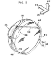
- the inner air bag body 34 is made of the cloth material 42 in which a large number of vent holes 40 are formed, but as shown in Fig. 5, the inner air bag body 34 may be made of a meshed (coarsely woven) cloth material 54 as the cloth material having a high gas permeability.
- the air bag device of the present invention is applied to the air bag device 10 for a driver's seat, which is provided to unfold in a region at the front side of the vehicle occupant 16 seated in the driver's seat 14.
- the air bag device of the present invention can also be applied to an air bag device 64 for a front passenger's seat, which is provided to unfold in a region at the front of a vehicle occupant 62 seated in a front passenger's seat.
- the air bag device of the present invention can be applied to other various air bag devices, for example, a side air bag device in which an air bag body accommodated along a front pillar and a roof side rail expands to unfold along a side portion of the interior of a vehicle similarly to a curtain or in a tubular form, a side air bag device in which an air bag body accommodated in a seat or in a side door expands to unfold along an vehicle-interior side portion of the side door, and the like.
- a side air bag device in which an air bag body accommodated along a front pillar and a roof side rail expands to unfold along a side portion of the interior of a vehicle similarly to a curtain or in a tubular form
- a side air bag device in which an air bag body accommodated in a seat or in a side door expands to unfold along an vehicle-interior side portion of the side door, and the like.
- the present invention discloses an air bag device having an air bag body which expands to unfold in an interior of a vehicle, the air bag body comprising: an outer air bag body having vent holes communicating with an exterior of the air bag body; and an inner air bag body having a capacity smaller than that of the outer air bag body and unfolding in an interior of the outer air bag body, wherein the inner air bag body is formed so as to have a high gas permeability, and when a vehicle occupant abuts against the outer air bag body, a portion of the outer air bag body pressed by the vehicle occupant abuts the inner air bag body so as to control a quantity of gas flowing from the inner air bag body into the outer air bag body.
- the present invention discloses an air bag device according to claim 1, wherein the inner air bag body is made of a cloth material having a large number of vent holes formed therein.
- the present invention discloses an air bag device according to claim 1, wherein the inner air bag body is made of a cloth material having a high gas permeability.
- the present invention discloses an air bag device having an air bag body which unfolds in an interior of a vehicle, the air bag body comprising: an outer air bag body; and an inner air bag body having a capacity smaller than that of the outer air bag body and unfolding in an interior of the outer air bag body, wherein the outer air bag body includes at least one first hole formed therein, and the inner air bag body includes communication means which is formed at least on a facing surface thereof substantially facing a vehicle occupant at the time of unfolding the air bag body, the communication means being provided to allow communication between an interior of the inner air bag body and a space formed between the inner air bag body and the outer air bag body.
- an air bag device of the present invention which allows generation of suitable reaction force which corresponds to a physical constitution of a vehicle occupant abutting against an air bag body.
- a region of an outer air bag body pressed by the vehicle occupant abuts an inner air bag body and closes vent holes formed in the inner air bag body. Therefore, a quantity of gas flowing from the inner air bag body into a space formed between the outer air bag body and the inner air bag body can be controlled. Accordingly, the quantity of gas flowing through the vent holes into the space and further escaping from the air bag body via vent holes formed in the outer air bag body can be adjusted in accordance with a physical constitution of the vehicle occupant abutting against the air bag body.
Landscapes
- Engineering & Computer Science (AREA)
- Mechanical Engineering (AREA)
- Air Bags (AREA)
Claims (13)
- Eine Airbagvorrichtung mit einem Airbagkörper (18), der sich ausdehnt, um sich im Innenraum eines Kraftfahrzeugs zu entfalten, wobei dieser Airbagkörper folgendes umfasst: einen äußeren Airbag (32) mit Belüftungslöchern (46), die mit einem Äußeren dieses Airbagkörpers kommunizieren; und einen inneren Airbagkörper (34) der eine Kapazität hat, die kleiner als die dieses äußeren Airbagkörpers ist, und der sich in einem Inneren dieses äußeren Airbagkörpers entfaltet, wobei dieser innere Airbagkörper so gestaltet ist, dass er eine hohe Gasdurchlässigkeit aufweist; dadurch gekennzeichnet, dass,
wenn ein Fahrzeuginsasse gegen diesen äußeren Airbagkörper (32) stößt, ein Bereich dieses äußeren Airbagkörpers (32), der durch den Fahrzeuginsassen gedrückt wird, so gegen diesen inneren Airbagkörper (34) stößt, dass eine Menge Gas kontrolliert wird, die von diesem inneren Airbagkörper in diesen äußeren Airbagkörper strömt. - Eine Airbagvorrichtung nach Anspruch 1; wobei dieser innere Airbagkörper aus einem Gewebematerial mit einer großen Zahl darin vorgesehener Belüftungslöcher besteht.
- Eine Airbagvorrichtung nach Anspruch 1; wobei dieser innere Airbagkörper aus einem Gewebematerial mit einer hohen Gasdurchlässigkeit besteht.
- Eine Airbagvorrichtung nach Anspruch 1; wobei dieser innere Airbagkörper (34) eine Kommunikationsvorrichtung enthält, die mindestens an einer gegenüberliegenden Oberfläche davon vorgesehen ist, die im Wesentlichen einem Fahrzeuginsassen zum Zeitpunkt des Entfaltens des Airbagkörpers gegenüberliegt, wobei diese Kommunikationsvorrichtung vorgesehen ist, um eine Kommunikation zwischen einem Inneren dieses inneren Airbagkörpers und einem Raum zu ermöglichen, der zwischen diesem inneren Airbagkörper und diesem äußeren Airbagkörper gebildet wird.
- Eine Airbagvorrichtung nach Anspruch 4; wobei diese Kommunikationsvorrichtung eine Vielzahl von Sekundärlöchern ist, die in diesem inneren Airbagkörper vorgesehen ist.
- Eine Airbagvorrichtung nach Anspruch 5; wobei zum Zeitpunkt des Entfaltens dieses Airbagkörpers entsprechend einer Anzahl dieser Sekundärlöcher, die durch diesen äußeren Airbagkörper, der vom Fahrzeuginsassen gedrückt wird, geschlossen werden, eine Menge Gas, die aus dem Inneren dieses inneren Airbagkörpers in den Raum strömt, der zwischen diesem inneren Airbagkörper und diesem äußeren Airbagkörper gebildet wird, gesteuert wird.
- Eine Airbagvorrichtung nach Anspruch 4; wobei diese Kommunikationsvorrichtung ein Gewebeelement ist, das luftdurchlässig ist.
- Eine Airbagvorrichtung nach Anspruch 7; wobei zum Zeitpunkt des Entfaltens dieses Airbagkörpers entsprechend einer Fläche dieses Gewebeelements, das durch diesen äußeren Airbagkörper, der vom Fahrzeuginsassen gedrückt wird, gedrückt wird, eine Menge Gas, das aus dem Inneren dieses inneren Airbagkörpers in den Raum strömt, der zwischen diesem inneren Airbagkörper und diesem äußeren Airbagkörper gebildet wird, gesteuert wird.
- Eine Airbagvorrichtung nach Anspruch 4; wobei zum Zeitpunkt des Entfaltens dieses Airbagkörpers aufgrund eines gedrückten Bereichs dieses äußeren Airbagkörpers, der durch den Fahrzeuginsassen gedrückt wird, der gegen einen gedrückten Bereich dieses inneren Airbagkörpers drückt, der durch diesen gedrückten Bereich gedrückt wird, ein Bereich dieser Kommunikationsvorrichtung in diesem gedrückten Bereich in einen nicht kommunizierenden Zustand versetzt wird.
- Eine Airbagvorrichtung nach Anspruch 9; wobei aufgrund der Änderung der Fläche dieses gedrückten Bereichs entsprechend einer physischen Konstitution des Fahrzeuginsassen, der gegen diesen äußeren Airbagkörper drückt, eine Menge Gas gesteuert wird, die aus dem Inneren dieses inneren Airbagkörpers in den Raum strömt, der zwischen diesem inneren Airbagkörper und diesem äußeren Airbagkörper gebildet wird.
- Eine Airbagvorrichtung nach Anspruch 4; wobei das erste Loch eine Kommunikation zwischen einem Raum, der zwischen diesem inneren Airbagkörper und diesem äußeren Airbagkörper gebildet wird, und einem Äußeren dieses äußeren Airbagkörpers ermöglicht.
- Eine Airbagvorrichtung nach Anspruch 4; die zusätzlich eine Präventionsvorrichtung umfasst, die verhindert, dass dieser innere Airbagkörper gegen das erste Loch, das in diesem äußeren Airbagkörper vorgesehen ist, zum Zeitpunkt des Entfaltens dieses Airbagkörpers drückt.
- Eine Airbagvorrichtung nach Anspruch 12; wobei diese Präventionsvorrichtung derartig geformt ist, dass ein Ende davon an einem Bereich dieses inneren Airbagkörpers in der Nähe des ersten Lochs zum Zeitpunkt des Entfaltens dieses Airbagkörpers befestigt ist und ein anderes Ende davon an einem Generator zum Entfalten dieses Airbagkörpers und einem Bereich in der Nähe des Generators befestigt ist.
Applications Claiming Priority (2)
| Application Number | Priority Date | Filing Date | Title |
|---|---|---|---|
| JP10561199 | 1999-04-13 | ||
| JP10561199A JP3463598B2 (ja) | 1999-04-13 | 1999-04-13 | エアバッグ装置 |
Publications (3)
| Publication Number | Publication Date |
|---|---|
| EP1044855A2 EP1044855A2 (de) | 2000-10-18 |
| EP1044855A3 EP1044855A3 (de) | 2001-11-07 |
| EP1044855B1 true EP1044855B1 (de) | 2003-12-03 |
Family
ID=14412308
Family Applications (1)
| Application Number | Title | Priority Date | Filing Date |
|---|---|---|---|
| EP00107889A Expired - Lifetime EP1044855B1 (de) | 1999-04-13 | 2000-04-12 | Airbagvorrichtung |
Country Status (4)
| Country | Link |
|---|---|
| US (1) | US6419267B1 (de) |
| EP (1) | EP1044855B1 (de) |
| JP (1) | JP3463598B2 (de) |
| DE (1) | DE60006886T2 (de) |
Cited By (7)
| Publication number | Priority date | Publication date | Assignee | Title |
|---|---|---|---|---|
| DE102004048898A1 (de) * | 2004-10-06 | 2006-09-07 | Autoliv Development Ab | Gassack und Kraftfahrzeug |
| DE102005019748A1 (de) * | 2005-04-28 | 2006-11-02 | Autoliv Development Ab | Gassack und Gassack-Einheit |
| US7695003B2 (en) | 2004-01-23 | 2010-04-13 | Takata-Petri Ag | Side protection device |
| US7850200B2 (en) | 2004-09-01 | 2010-12-14 | Autoliv Development Ab | Airbag and a motor vehicle |
| US7862076B2 (en) | 2004-02-06 | 2011-01-04 | Autoliv Development Ab | Airbag for installation in a motor vehicle |
| US7988188B2 (en) | 2007-08-02 | 2011-08-02 | Autoliv Development Ab | Side airbag having hose as ventilation opening |
| EP1568544B2 (de) † | 2004-02-25 | 2013-05-22 | TRW Automotive GmbH | Seitenaufprall-Rückhaltevorrichtung |
Families Citing this family (71)
| Publication number | Priority date | Publication date | Assignee | Title |
|---|---|---|---|---|
| JP4129758B2 (ja) * | 1998-08-10 | 2008-08-06 | 俊毅 内田 | エアバッグ装置 |
| US6962363B2 (en) * | 2000-07-07 | 2005-11-08 | Milliken & Company | Multiple chamber airbags and methods |
| JP4560984B2 (ja) * | 2001-04-13 | 2010-10-13 | タカタ株式会社 | 運転席用エアバッグ装置 |
| DE20207388U1 (de) * | 2001-11-02 | 2002-08-14 | Takata Petri Gmbh Ulm | Airbaganordnung |
| JP3932867B2 (ja) * | 2001-11-07 | 2007-06-20 | 豊田合成株式会社 | 助手席用エアバッグ装置 |
| US6991258B2 (en) * | 2002-02-20 | 2006-01-31 | Delphi Technologies, Inc. | Frontal air bag system |
| US7566074B2 (en) * | 2002-02-20 | 2009-07-28 | Delphi Technologies, Inc. | Apparatus and method for controlling an inflatable cushion |
| US7543848B2 (en) * | 2002-02-20 | 2009-06-09 | Delphi Technologies, Inc. | Apparatus and method for controlling an inflatable cushion |
| US7819425B2 (en) * | 2002-02-20 | 2010-10-26 | Autoliv Development Ab | Apparatus and method for controlling an inflatable cushion |
| US7021657B2 (en) * | 2002-11-08 | 2006-04-04 | Delphi Technologies, Inc. | Air bag including variable tethers |
| US6932384B2 (en) * | 2002-11-15 | 2005-08-23 | Delphi Technologies, Inc. | Apparatus and method for controlling an inflatable cushion |
| US6869103B2 (en) * | 2002-12-13 | 2005-03-22 | Delphi Technologies, Inc. | Apparatus and method for controlling an inflatable cushion |
| JP2004210257A (ja) * | 2002-12-18 | 2004-07-29 | Takata Corp | 頭部保護エアバッグ及び頭部保護エアバッグ装置 |
| JP2005104323A (ja) * | 2003-09-30 | 2005-04-21 | Toyoda Gosei Co Ltd | ステアリングホイール用エアバッグ |
| JP4935064B2 (ja) * | 2005-01-11 | 2012-05-23 | タカタ株式会社 | エアバッグ及びエアバッグ装置 |
| DE102004004544A1 (de) * | 2004-01-23 | 2005-08-11 | Takata-Petri (Ulm) Gmbh | Verfahren zum Schützen eines Fahrzeuginsassen im Falle eines Unfalls |
| JP4604765B2 (ja) * | 2004-03-08 | 2011-01-05 | タカタ株式会社 | エアバッグ装置 |
| DE202004006655U1 (de) * | 2004-04-27 | 2004-09-09 | Trw Automotive Safety Systems Gmbh | Gassack |
| DE102005002962A1 (de) * | 2005-01-21 | 2006-08-03 | Bst Safety Textiles Gmbh | Personenrückhaltesystem |
| DE102005003703A1 (de) | 2005-01-26 | 2006-08-24 | Trw Automotive Gmbh | Gassack mit Abströmöffnung |
| JP4735021B2 (ja) * | 2005-04-26 | 2011-07-27 | タカタ株式会社 | エアバッグ装置 |
| US7350807B2 (en) | 2005-05-25 | 2008-04-01 | Autoliv Asp, Inc. | Divided airbag system |
| US20060284403A1 (en) * | 2005-06-21 | 2006-12-21 | Trw Vehicle Safety Systems Inc. | Inflatable vehicle occupant protection device construction |
| JP2007055577A (ja) * | 2005-07-29 | 2007-03-08 | Takata Corp | エアバッグ及びエアバッグ装置 |
| US7325830B2 (en) * | 2005-09-05 | 2008-02-05 | Honda Motor Co., Ltd. | Airbag device for vehicles |
| DE202005016279U1 (de) * | 2005-10-18 | 2006-03-02 | Trw Automotive Safety Systems Gmbh | Gassackmodul für ein Fahrzeuginsassen-Rückhaltesystem |
| US7523891B2 (en) * | 2005-12-21 | 2009-04-28 | A-Hamid Hakki | Safety pre-impact deceleration system for vehicles |
| US7942440B2 (en) * | 2005-12-22 | 2011-05-17 | Autoliv Asp, Inc. | Channel and diffuser airbag |
| KR100778578B1 (ko) | 2006-10-31 | 2007-11-22 | 현대자동차주식회사 | 보조챔버가 구비된 차량용 에어백 장치 |
| DE102006038124B4 (de) | 2006-08-14 | 2019-05-23 | Daimler Ag | Rückhaltesystem für ein Kraftfahrzeug |
| EP2263921B1 (de) * | 2006-10-26 | 2011-10-12 | Ashimori Industry Co., Ltd. | Airbagvorrichtung |
| DE102006051553B4 (de) * | 2006-11-02 | 2009-08-20 | Autoliv Development Ab | Seitengassack |
| DE102006051552B4 (de) * | 2006-11-02 | 2015-10-15 | Autoliv Development Ab | Seitengassack |
| JP2010523398A (ja) * | 2007-04-03 | 2010-07-15 | デルファイ・テクノロジーズ・インコーポレーテッド | 膨張可能なクッションを制御するための装置及び方法 |
| DE202007005342U1 (de) * | 2007-04-05 | 2007-06-28 | Takata-Petri Ag | Gassack für ein Kraftfahrzeug |
| EP1990248B1 (de) * | 2007-05-09 | 2010-10-27 | Dalphi Metal España, S.A. | Seitenairbag mit adaptiver Entlüftungsvorrichtung |
| EP2008879B1 (de) * | 2007-06-29 | 2012-06-27 | Dalphi Metal España, S.A. | Adaptiver Dreikammer-Seitenairbag |
| DE102008037812A1 (de) * | 2007-11-02 | 2009-06-04 | Daimler Ag | Fahrzeuginsassensicherheitssystem mit variabler Abstützung und entsprechendes Betriebsverfahren |
| JP4798137B2 (ja) * | 2008-01-11 | 2011-10-19 | トヨタ自動車株式会社 | 車両用乗員拘束装置 |
| DE102008008787A1 (de) * | 2008-02-12 | 2009-08-13 | Daimler Ag | Rückhaltesystem |
| US20090200777A1 (en) * | 2008-02-13 | 2009-08-13 | Webber James L | Apparatus and method for controlling an inflatable cushion |
| JP4640419B2 (ja) | 2008-02-22 | 2011-03-02 | トヨタ自動車株式会社 | 車両用エアバッグ装置 |
| JP5286825B2 (ja) * | 2008-02-25 | 2013-09-11 | タカタ株式会社 | エアバッグ及びエアバッグ装置 |
| US8191925B2 (en) * | 2008-04-14 | 2012-06-05 | Autoliv Asp, Inc. | Dynamic safety vent |
| KR101540075B1 (ko) * | 2008-11-21 | 2015-07-28 | 아우토리브 디벨롭먼트 아베 | 측면 에어백 모듈 |
| US7938445B2 (en) * | 2009-03-03 | 2011-05-10 | Autoliv Asp, Inc. | Dual chamber airbag cushions with a safety vent in the front chamber |
| US7946613B2 (en) * | 2009-03-03 | 2011-05-24 | Autoliv Asp, Inc. | Dual chamber airbag cushion |
| US8226118B2 (en) | 2009-08-05 | 2012-07-24 | Autoliv Asp, Inc. | Safety venting with passively closeable vents |
| US8371612B2 (en) * | 2009-09-17 | 2013-02-12 | Autoliv Asp, Inc. | Inflatable airbag assemblies with lateral and longitudinal tethers |
| CN203358520U (zh) | 2012-04-27 | 2013-12-25 | 福特环球技术公司 | 安全气囊 |
| US8646808B2 (en) | 2012-06-18 | 2014-02-11 | Autoliv Asp, Inc. | Airbag with active vent |
| US8882143B2 (en) | 2013-02-08 | 2014-11-11 | Autoliv Asp, Inc. | Airbag with slit vent |
| WO2014134365A1 (en) | 2013-02-28 | 2014-09-04 | Tk Holdings Inc. | Dual chambered passenger airbag |
| US9381885B2 (en) | 2013-03-01 | 2016-07-05 | Tk Holdings Inc. | Tether airbag control system |
| US9266493B2 (en) | 2013-04-10 | 2016-02-23 | Tk Holdings Inc. | Two-way valve for multi-chambered airbags |
| WO2015112644A1 (en) * | 2014-01-21 | 2015-07-30 | Tk Holdings Inc. | Passenger side airbag |
| GB2524292A (en) * | 2014-03-19 | 2015-09-23 | Ford Global Tech Llc | An airbag system |
| US9016721B1 (en) * | 2014-05-13 | 2015-04-28 | Autoliv Asp, Inc. | Airbag assemblies with adaptive venting |
| FR3022513A1 (fr) * | 2014-06-20 | 2015-12-25 | Peugeot Citroen Automobiles Sa | Coussin de securite automobile |
| JP6274164B2 (ja) * | 2015-07-28 | 2018-02-07 | トヨタ自動車株式会社 | 運転席用エアバッグ装置 |
| JP2017074850A (ja) * | 2015-10-14 | 2017-04-20 | 三菱自動車工業株式会社 | サイドエアバッグ装置 |
| US10093270B2 (en) | 2016-01-13 | 2018-10-09 | Autoliv Asp, Inc. | Multi-flap vents for inflatable chambers |
| DE102016107484B4 (de) * | 2016-04-22 | 2018-12-06 | Autoliv Development Ab | Frontgassack zum Einbau in ein Kraftfahrzeug |
| US9845069B1 (en) * | 2016-09-01 | 2017-12-19 | Ford Global Technologies, Llc | Airbag including compressible vent tube |
| JP6680233B2 (ja) * | 2017-02-02 | 2020-04-15 | 豊田合成株式会社 | エアバッグ |
| US10829082B2 (en) | 2018-01-31 | 2020-11-10 | Nissan North America, Inc. | Airbag device |
| US10589707B2 (en) * | 2018-02-02 | 2020-03-17 | Toyoda Gosei Co., Ltd. | Airbag apparatus |
| JP7001018B2 (ja) * | 2018-08-10 | 2022-01-19 | 豊田合成株式会社 | エアバッグ |
| US11198411B2 (en) * | 2019-04-18 | 2021-12-14 | Autoliv Asp. Inc. | Energy-absorbing airbag diffusers and related airbag assemblies |
| US11292423B2 (en) | 2020-05-18 | 2022-04-05 | Autoliv Asp, Inc. | Vent flap for airbag assemblies |
| US11891012B2 (en) * | 2021-05-05 | 2024-02-06 | ZF Passive Safety Systems US Inc. | One-piece woven occupant restraint system |
Family Cites Families (18)
| Publication number | Priority date | Publication date | Assignee | Title |
|---|---|---|---|---|
| JPH01311930A (ja) * | 1988-06-09 | 1989-12-15 | Nippon Plast Co Ltd | 自動車等の乗員保護装置 |
| JPH0352265A (ja) | 1989-07-20 | 1991-03-06 | Sanyo Electric Co Ltd | 薄膜トランジスタ |
| JPH03281460A (ja) | 1990-03-29 | 1991-12-12 | Mazda Motor Corp | 自動車のエアバッグ装置 |
| JP2946771B2 (ja) | 1991-01-31 | 1999-09-06 | 日産自動車株式会社 | エアバッグ装置 |
| JP3120506B2 (ja) | 1991-11-11 | 2000-12-25 | トヨタ自動車株式会社 | サイドエアバッグ装置 |
| US5249824A (en) * | 1991-11-19 | 1993-10-05 | Trw Inc. | Air bag structure and method of forming |
| US5338061A (en) * | 1992-04-08 | 1994-08-16 | Daicel Chemical Industries, Ltd. | Air bag having double-wall construction |
| CA2108394A1 (en) | 1992-12-01 | 1994-06-02 | Thomas M. Kriska | Air bag cushion with fabric diffuser |
| US5282646A (en) * | 1993-02-16 | 1994-02-01 | General Motors Corporation | Multi-chamber air bag with displacement responsive valve |
| US5489117A (en) * | 1994-07-25 | 1996-02-06 | Huber; John F. | Occupant restraint system |
| JPH1044914A (ja) | 1995-08-11 | 1998-02-17 | Denso Corp | 助手席用エアバッグ装置 |
| US5951038A (en) * | 1995-08-11 | 1999-09-14 | Denso Corporation | Air bag device having inner and outer bags for selectively directed expansion thereof |
| JPH0948307A (ja) | 1995-08-11 | 1997-02-18 | Denso Corp | エアバッグの製造方法 |
| JPH1071904A (ja) | 1996-08-30 | 1998-03-17 | Denso Corp | エアバッグ装置 |
| JPH1071920A (ja) | 1996-08-30 | 1998-03-17 | Denso Corp | 助手席用エアバッグ装置 |
| JPH10203280A (ja) | 1997-01-20 | 1998-08-04 | Toyo Tire & Rubber Co Ltd | 助手席用エアバッグ装置 |
| US5927748A (en) * | 1997-06-26 | 1999-07-27 | O'driscoll; Peter | Multi-stage inflatable bag for vehicular safety systems |
| US6086092A (en) * | 1998-07-07 | 2000-07-11 | Trw Vehicle Safety Systems Inc. | Inflatable vehicle occupant protection device |
-
1999
- 1999-04-13 JP JP10561199A patent/JP3463598B2/ja not_active Expired - Fee Related
-
2000
- 2000-04-12 DE DE60006886T patent/DE60006886T2/de not_active Expired - Fee Related
- 2000-04-12 EP EP00107889A patent/EP1044855B1/de not_active Expired - Lifetime
- 2000-04-12 US US09/547,721 patent/US6419267B1/en not_active Expired - Fee Related
Cited By (7)
| Publication number | Priority date | Publication date | Assignee | Title |
|---|---|---|---|---|
| US7695003B2 (en) | 2004-01-23 | 2010-04-13 | Takata-Petri Ag | Side protection device |
| US7862076B2 (en) | 2004-02-06 | 2011-01-04 | Autoliv Development Ab | Airbag for installation in a motor vehicle |
| EP1568544B2 (de) † | 2004-02-25 | 2013-05-22 | TRW Automotive GmbH | Seitenaufprall-Rückhaltevorrichtung |
| US7850200B2 (en) | 2004-09-01 | 2010-12-14 | Autoliv Development Ab | Airbag and a motor vehicle |
| DE102004048898A1 (de) * | 2004-10-06 | 2006-09-07 | Autoliv Development Ab | Gassack und Kraftfahrzeug |
| DE102005019748A1 (de) * | 2005-04-28 | 2006-11-02 | Autoliv Development Ab | Gassack und Gassack-Einheit |
| US7988188B2 (en) | 2007-08-02 | 2011-08-02 | Autoliv Development Ab | Side airbag having hose as ventilation opening |
Also Published As
| Publication number | Publication date |
|---|---|
| JP2000289560A (ja) | 2000-10-17 |
| US6419267B1 (en) | 2002-07-16 |
| EP1044855A2 (de) | 2000-10-18 |
| DE60006886D1 (de) | 2004-01-15 |
| JP3463598B2 (ja) | 2003-11-05 |
| EP1044855A3 (de) | 2001-11-07 |
| DE60006886T2 (de) | 2004-10-14 |
Similar Documents
| Publication | Publication Date | Title |
|---|---|---|
| EP1044855B1 (de) | Airbagvorrichtung | |
| US7770925B2 (en) | Airbag protection flap | |
| US5997032A (en) | Seat with side air bag | |
| US7770921B2 (en) | Airbag for protection of a vehicle occupant | |
| US7393011B2 (en) | Airbag with floating tethers | |
| US7549671B2 (en) | Knee-protecting airbag apparatus | |
| JP4420067B2 (ja) | 車両用エアバッグ装置 | |
| US20120074677A1 (en) | Airbag, airbag device, and method for sewing lid member of airbag | |
| US20040007857A1 (en) | Inflatable airbag deployment guide | |
| US7748730B2 (en) | Airbag system | |
| JPH07329688A (ja) | 車両用エアバッグの展開方法 | |
| US9821751B2 (en) | Airbag module | |
| US5306039A (en) | Passenger's air bag assembly | |
| JP4815945B2 (ja) | エアバッグ装置 | |
| WO2018123427A1 (ja) | サイドエアバッグ装置 | |
| EP2132063A1 (de) | Airbag zum schutz eines fahrzeuginsassen | |
| JPH07329694A (ja) | エアバッグの内圧調節装置 | |
| US7614649B2 (en) | Airbag system | |
| JP4244863B2 (ja) | 助手席用エアバッグ | |
| JP4394810B2 (ja) | エアバッグ装置 | |
| US20050110248A1 (en) | Airbag device | |
| EP1777122B1 (de) | Airbagsystem | |
| JPH08244552A (ja) | 側突用エアバッグ | |
| JP7298528B2 (ja) | 頭部保護エアバッグ装置 | |
| JPH10157540A (ja) | エアバッグ |
Legal Events
| Date | Code | Title | Description |
|---|---|---|---|
| PUAI | Public reference made under article 153(3) epc to a published international application that has entered the european phase |
Free format text: ORIGINAL CODE: 0009012 |
|
| 17P | Request for examination filed |
Effective date: 20000412 |
|
| AK | Designated contracting states |
Kind code of ref document: A2 Designated state(s): AT BE CH CY DE DK ES FI FR GB GR IE IT LI LU MC NL PT SE Kind code of ref document: A2 Designated state(s): DE FR GB |
|
| AX | Request for extension of the european patent |
Free format text: AL;LT;LV;MK;RO;SI |
|
| PUAL | Search report despatched |
Free format text: ORIGINAL CODE: 0009013 |
|
| AK | Designated contracting states |
Kind code of ref document: A3 Designated state(s): AT BE CH CY DE DK ES FI FR GB GR IE IT LI LU MC NL PT SE |
|
| AX | Request for extension of the european patent |
Free format text: AL;LT;LV;MK;RO;SI |
|
| 17Q | First examination report despatched |
Effective date: 20020220 |
|
| AKX | Designation fees paid |
Free format text: DE FR GB |
|
| GRAH | Despatch of communication of intention to grant a patent |
Free format text: ORIGINAL CODE: EPIDOS IGRA |
|
| GRAS | Grant fee paid |
Free format text: ORIGINAL CODE: EPIDOSNIGR3 |
|
| GRAA | (expected) grant |
Free format text: ORIGINAL CODE: 0009210 |
|
| AK | Designated contracting states |
Kind code of ref document: B1 Designated state(s): DE FR GB |
|
| REG | Reference to a national code |
Ref country code: GB Ref legal event code: FG4D |
|
| REF | Corresponds to: |
Ref document number: 60006886 Country of ref document: DE Date of ref document: 20040115 Kind code of ref document: P |
|
| ET | Fr: translation filed | ||
| PLBE | No opposition filed within time limit |
Free format text: ORIGINAL CODE: 0009261 |
|
| STAA | Information on the status of an ep patent application or granted ep patent |
Free format text: STATUS: NO OPPOSITION FILED WITHIN TIME LIMIT |
|
| 26N | No opposition filed |
Effective date: 20040906 |
|
| PGFP | Annual fee paid to national office [announced via postgrant information from national office to epo] |
Ref country code: DE Payment date: 20070405 Year of fee payment: 8 |
|
| PGFP | Annual fee paid to national office [announced via postgrant information from national office to epo] |
Ref country code: GB Payment date: 20070411 Year of fee payment: 8 |
|
| PGFP | Annual fee paid to national office [announced via postgrant information from national office to epo] |
Ref country code: FR Payment date: 20070411 Year of fee payment: 8 |
|
| GBPC | Gb: european patent ceased through non-payment of renewal fee |
Effective date: 20080412 |
|
| PG25 | Lapsed in a contracting state [announced via postgrant information from national office to epo] |
Ref country code: DE Free format text: LAPSE BECAUSE OF NON-PAYMENT OF DUE FEES Effective date: 20081101 |
|
| REG | Reference to a national code |
Ref country code: FR Ref legal event code: ST Effective date: 20081231 |
|
| PG25 | Lapsed in a contracting state [announced via postgrant information from national office to epo] |
Ref country code: FR Free format text: LAPSE BECAUSE OF NON-PAYMENT OF DUE FEES Effective date: 20080430 |
|
| PG25 | Lapsed in a contracting state [announced via postgrant information from national office to epo] |
Ref country code: GB Free format text: LAPSE BECAUSE OF NON-PAYMENT OF DUE FEES Effective date: 20080412 |