EP1035339A1 - Rollenlager und ein Herstellungsverfahren desselben - Google Patents
Rollenlager und ein Herstellungsverfahren desselben Download PDFInfo
- Publication number
- EP1035339A1 EP1035339A1 EP00104882A EP00104882A EP1035339A1 EP 1035339 A1 EP1035339 A1 EP 1035339A1 EP 00104882 A EP00104882 A EP 00104882A EP 00104882 A EP00104882 A EP 00104882A EP 1035339 A1 EP1035339 A1 EP 1035339A1
- Authority
- EP
- European Patent Office
- Prior art keywords
- shape
- roller
- generating line
- bearing
- zones
- Prior art date
- Legal status (The legal status is an assumption and is not a legal conclusion. Google has not performed a legal analysis and makes no representation as to the accuracy of the status listed.)
- Granted
Links
- 238000000034 method Methods 0.000 title claims description 13
- 238000005096 rolling process Methods 0.000 claims abstract description 43
- 238000007517 polishing process Methods 0.000 claims description 3
- 230000014509 gene expression Effects 0.000 description 20
- 238000009826 distribution Methods 0.000 description 3
- 239000002131 composite material Substances 0.000 description 1
- 238000010586 diagram Methods 0.000 description 1
- 230000000694 effects Effects 0.000 description 1
- 238000004519 manufacturing process Methods 0.000 description 1
- 230000002093 peripheral effect Effects 0.000 description 1
- 230000002035 prolonged effect Effects 0.000 description 1
Images
Classifications
-
- F—MECHANICAL ENGINEERING; LIGHTING; HEATING; WEAPONS; BLASTING
- F16—ENGINEERING ELEMENTS AND UNITS; GENERAL MEASURES FOR PRODUCING AND MAINTAINING EFFECTIVE FUNCTIONING OF MACHINES OR INSTALLATIONS; THERMAL INSULATION IN GENERAL
- F16C—SHAFTS; FLEXIBLE SHAFTS; ELEMENTS OR CRANKSHAFT MECHANISMS; ROTARY BODIES OTHER THAN GEARING ELEMENTS; BEARINGS
- F16C19/00—Bearings with rolling contact, for exclusively rotary movement
- F16C19/22—Bearings with rolling contact, for exclusively rotary movement with bearing rollers essentially of the same size in one or more circular rows, e.g. needle bearings
- F16C19/34—Bearings with rolling contact, for exclusively rotary movement with bearing rollers essentially of the same size in one or more circular rows, e.g. needle bearings for both radial and axial load
- F16C19/36—Bearings with rolling contact, for exclusively rotary movement with bearing rollers essentially of the same size in one or more circular rows, e.g. needle bearings for both radial and axial load with a single row of rollers
- F16C19/364—Bearings with rolling contact, for exclusively rotary movement with bearing rollers essentially of the same size in one or more circular rows, e.g. needle bearings for both radial and axial load with a single row of rollers with tapered rollers, i.e. rollers having essentially the shape of a truncated cone
-
- F—MECHANICAL ENGINEERING; LIGHTING; HEATING; WEAPONS; BLASTING
- F16—ENGINEERING ELEMENTS AND UNITS; GENERAL MEASURES FOR PRODUCING AND MAINTAINING EFFECTIVE FUNCTIONING OF MACHINES OR INSTALLATIONS; THERMAL INSULATION IN GENERAL
- F16C—SHAFTS; FLEXIBLE SHAFTS; ELEMENTS OR CRANKSHAFT MECHANISMS; ROTARY BODIES OTHER THAN GEARING ELEMENTS; BEARINGS
- F16C23/00—Bearings for exclusively rotary movement adjustable for aligning or positioning
- F16C23/06—Ball or roller bearings
- F16C23/08—Ball or roller bearings self-adjusting
- F16C23/088—Ball or roller bearings self-adjusting by means of crowning
-
- F—MECHANICAL ENGINEERING; LIGHTING; HEATING; WEAPONS; BLASTING
- F16—ENGINEERING ELEMENTS AND UNITS; GENERAL MEASURES FOR PRODUCING AND MAINTAINING EFFECTIVE FUNCTIONING OF MACHINES OR INSTALLATIONS; THERMAL INSULATION IN GENERAL
- F16C—SHAFTS; FLEXIBLE SHAFTS; ELEMENTS OR CRANKSHAFT MECHANISMS; ROTARY BODIES OTHER THAN GEARING ELEMENTS; BEARINGS
- F16C33/00—Parts of bearings; Special methods for making bearings or parts thereof
- F16C33/30—Parts of ball or roller bearings
- F16C33/34—Rollers; Needles
- F16C33/36—Rollers; Needles with bearing-surfaces other than cylindrical, e.g. tapered; with grooves in the bearing surfaces
- F16C33/366—Tapered rollers, i.e. rollers generally shaped as truncated cones
-
- F—MECHANICAL ENGINEERING; LIGHTING; HEATING; WEAPONS; BLASTING
- F16—ENGINEERING ELEMENTS AND UNITS; GENERAL MEASURES FOR PRODUCING AND MAINTAINING EFFECTIVE FUNCTIONING OF MACHINES OR INSTALLATIONS; THERMAL INSULATION IN GENERAL
- F16C—SHAFTS; FLEXIBLE SHAFTS; ELEMENTS OR CRANKSHAFT MECHANISMS; ROTARY BODIES OTHER THAN GEARING ELEMENTS; BEARINGS
- F16C33/00—Parts of bearings; Special methods for making bearings or parts thereof
- F16C33/30—Parts of ball or roller bearings
- F16C33/58—Raceways; Race rings
- F16C33/583—Details of specific parts of races
- F16C33/585—Details of specific parts of races of raceways, e.g. ribs to guide the rollers
-
- F—MECHANICAL ENGINEERING; LIGHTING; HEATING; WEAPONS; BLASTING
- F16—ENGINEERING ELEMENTS AND UNITS; GENERAL MEASURES FOR PRODUCING AND MAINTAINING EFFECTIVE FUNCTIONING OF MACHINES OR INSTALLATIONS; THERMAL INSULATION IN GENERAL
- F16C—SHAFTS; FLEXIBLE SHAFTS; ELEMENTS OR CRANKSHAFT MECHANISMS; ROTARY BODIES OTHER THAN GEARING ELEMENTS; BEARINGS
- F16C2240/00—Specified values or numerical ranges of parameters; Relations between them
- F16C2240/40—Linear dimensions, e.g. length, radius, thickness, gap
- F16C2240/50—Crowning, e.g. crowning height or crowning radius
-
- Y—GENERAL TAGGING OF NEW TECHNOLOGICAL DEVELOPMENTS; GENERAL TAGGING OF CROSS-SECTIONAL TECHNOLOGIES SPANNING OVER SEVERAL SECTIONS OF THE IPC; TECHNICAL SUBJECTS COVERED BY FORMER USPC CROSS-REFERENCE ART COLLECTIONS [XRACs] AND DIGESTS
- Y10—TECHNICAL SUBJECTS COVERED BY FORMER USPC
- Y10T—TECHNICAL SUBJECTS COVERED BY FORMER US CLASSIFICATION
- Y10T29/00—Metal working
- Y10T29/49—Method of mechanical manufacture
- Y10T29/49636—Process for making bearing or component thereof
- Y10T29/49643—Rotary bearing
- Y10T29/49679—Anti-friction bearing or component thereof
- Y10T29/49689—Race making
-
- Y—GENERAL TAGGING OF NEW TECHNOLOGICAL DEVELOPMENTS; GENERAL TAGGING OF CROSS-SECTIONAL TECHNOLOGIES SPANNING OVER SEVERAL SECTIONS OF THE IPC; TECHNICAL SUBJECTS COVERED BY FORMER USPC CROSS-REFERENCE ART COLLECTIONS [XRACs] AND DIGESTS
- Y10—TECHNICAL SUBJECTS COVERED BY FORMER USPC
- Y10T—TECHNICAL SUBJECTS COVERED BY FORMER US CLASSIFICATION
- Y10T29/00—Metal working
- Y10T29/49—Method of mechanical manufacture
- Y10T29/49636—Process for making bearing or component thereof
- Y10T29/49643—Rotary bearing
- Y10T29/49679—Anti-friction bearing or component thereof
- Y10T29/49693—Roller making
Definitions
- the invention relates to a roller bearing in which cylindrical rollers or tapered rollers are used as rolling elements, and particularly to a roller bearing that is suitably used in a portion to which a heavy load or a high momentum load is applied.
- a crowning process is applied to the rolling surfaces of the rollers and the raceway surfaces of the inner and outer races, so that the edge load which acts under load conditions between end portions of the roller rolling surface and the raceway surfaces can be reduced.
- the crowning process is applied to the generating line of the rolling surface of each roller or the raceway surface of the inner or outer race so that the outer diameter of each end portion is slightly smaller than that of the center portion.
- a trapezoid or a simple circular arc is practically used as the crowning shape (the shape of the profile line to the direction of the generating line).
- a method in which crowning to a shape of a logarithmic curve based on the elastic contact theory is employed may be applied on such a bearing to which a heavy load or a high momentum load is applied.
- Zp(x) indicates the size of a gap between the rolling surface of a roller and the raceway surface of the inner or outer race, in the bearing radial direction (z-direction) at a position in the direction of the common generating line (x-direction) in a state where the rolling surface and the raceway surface are contacted with each other in an unloaded condition.
- the origin of the x-axis is set at the center in the axial direction of the roller.
- Both the expressions (1) and (2) based on the elastic contact theory are special logarithmic curves.
- the shape of the profile line in the direction of the generating line (hereinafter, such a shape is referred to merely as "generating line shape") of at least one of the roller rolling surface and the raceway surface must be processed into a shape corresponding to such a logarithmic curve.
- an NC (Numerically Controlled) grinding machine is usually used.
- the surface of a grindstone is dressed into the negative shape of the desired curve shape by a dressing mechanism of the grinding machine, and the surface of the article is then ground.
- a dressing mechanism of an NC grinding machine usually operates only along a linear or arcuate locus. In a practical use, therefore, it is very difficult to, in order to obtain a gap indicated by a logarithmic curve of the above-mentioned expression (1) or (2), grind the generating line shape of the rolling surface of the roller or the raceway surface of the inner or outer race, into the shape of the desired logarithmic curve.
- the invention has been conducted in view of the above-mentioned circumstances. It is an object of the invention to provide a practical roller bearing having a crowning shape that allows a gap substantially corresponding to a theoretically calculated gap based on the elastic contact theory indicated by the above-mentioned expression (1) or (2) to be formed between the roller rolling surface and the raceway surface of at lest one of the inner and outer races, thereby realizing a long life period even when a heavy load or a high momentum load is applied.
- the generating line shape of one of the roller rolling surface and the raceway surfaces of the inner and outer races is not formed by a special curve shape corresponding to the special curve, but the special curve shape is approximated by a set of a plurality of circular arcs. Therefore, a practical processing by a usual NC grinding machine is enabled, thereby attaining the intended object.
- the generating line shape of the rolling surface of each roller or the raceway surface of the inner or outer race is divided into a plurality of zones in the direction of the generating line, and a special curve shape A(x) based on a theoretical calculation is approximated for each of the zones by using the circle equation indicated by expression (3).
- a method may be used in which the circle equation in each zone is determined while using conditions that the circular arc of each zone passes coordinate P i (x i , y i ) of the special curve shape A(x) on a border line of the zone to which the circular arc belongs, and that adjacent circular arcs are contacted with each other on the border line between the corresponding zones.
- the special curve shape A can be smoothly approximated by the plurality of circular arcs.
- the generating line may be divided into any number of zones. However, it has been confirmed that a division number of 10 or less allows the maximum contact surface pressure to have a value which is substantially equal to that of a theoretical shape.
- the processing of the generating line shape may be performed only on the rolling surface of each roller, only the raceway surface of the inner or outer race, or both of the rolling surface of each roller and the raceway surface of the inner or outer race.
- the gap between the rolling surface of a roller and the raceway surface of the inner race, or that between the rolling surface of a roller and the raceway surface of the outer race is a theoretically calculated gap such as the gap Z(x) indicated by the above-mentioned expression (2).
- Z(x) indicated by the expression (2) or (2)' is employed as the theoretical gap, any one of the following modes may be employed.
- the generating line shape of the other one may be set to have a curve shape of Z(x) itself.
- the other generating line shape may be a curve which is obtained by subtracting the arc curve from the curve of Z(x).
- both of the generating line shapes may be a curve of Z(x)/2. The invention includes all of these modes.
- the invention includes also a configuration in which one or both of the gap between the roller rolling surface and the raceway surface of the inner race, and the gap between the roller rolling surface and the raceway surface of the outer race are formed as a gap based on the crowning shape.
- the effect of improving the life period of the bearing can be attained in a practical use even when only the gap between the inner race and each roller in which the contact surface pressure is higher, and which easily causes a bottleneck in the life period of the bearing is formed as such a gap.
- the theoretical value of the gap which is to be formed between the roller rolling surface and the raceway surface of the inner or outer race and at a position in the direction of the common generating line is specified to the value Z(x) indicated by the expression (2) or (2)'. It has been confirmed that the theoretical value Z(x) is more effective to an actual bearing than the value Zp(x) based on Lundberg's expression.
- the generating line shape of at least one of a roller and the bearing ring is approximated by a plurality of circular arcs so as to obtain the gap of Zp(x), the contact stress between the roller and the raceway can be very highly uniformalized, whereby the life period of the bearing can be prolonged.
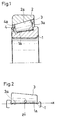
- Fig. 1 is an axial section view of an embodiment in which the invention is applied to a tapered roller bearing.
- a plurality of tapered rollers 3 which are rollable and in each of which a rolling surface 3a configured by a conical surface is formed on the outer periphery, and a cage 4 in which pockets 4a that respectively house the tapered rollers 3 so as to define the mutual peripheral positions of the tapered rollers 3 are formed at a regular pitch are disposed between an inner race 1 in which a raceway surface 1a configured by a conical surface is formed on the outer periphery, and an outer race 2 in which a raceway surface 2a configured by a conical inner surface is formed on the inner periphery.
- a crowning process which is a characteristic configuration of the invention is applied to the raceway surface 1a of the inner race 1, and the rolling surfaces 3a of the tapered rollers 3.
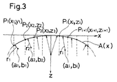
- a coordinate which is defined in Fig. 2 is used.
- the direction of the common generating line in a contact portion between the raceway surface 1a of the inner race 1 and the rolling surface 3a of each of the tapered rollers 3 is set as the x-direction
- the radial direction of the bearing, i.e., the depth direction of the crowning is set as the z-direction
- the origins of the x- and z-axes are set at the center in the axial direction on the generating line of the rolling surface 3a of the tapered roller 3.
- the generating line shape of the rolling surfaces 3a of the tapered rollers 3 is set to a simple arcuate crowning shape which can be easily obtained by, for example, through-feed grinding using a centerless grinding machine.
- the generating line shape of the raceway surface 1a of the inner race 1 is set to a shape in which a special logarithmic curve A(x) is approximated by a plurality of circular arcs as described in detail later.
- Z(x) Z(x) - B(x)
- the generating line shape of the raceway surface 1a of the inner race 1 is set to be bilaterally symmetrical with respect to the origin which is at the center of the direction of the generating line (direction of the x-axis).
- the generating line shape of the raceway surface 1a of the inner race 1 is approximated by the n number of circular arcs so as to substantially coincide with the special logarithmic curve A(x).
- the coefficients a i , b i , and r i of the equation of the circular arcs can be determined in accordance with the following two conditions.
- the special logarithmic curve A(x) can be smoothly approximated by a plurality of circular arcs.
- Such a generating line shape of the raceway surface 1a of the inner race 1 can be easily processed by a usual NC grinding machine having a dressing mechanism which operates along an arcuate locus.
- a tapered roller bearing By a combination of the inner race 1 having such a generating line shape of the raceway surface 1a, and the tapered rollers 3 having the above-mentioned generating line shape of the rolling surfaces 3a, a tapered roller bearing can be obtained in which a gap between the raceway surface 1a of the inner race 1 and the rolling surface 3a of each of the tapered rollers 3 at a position in the direction of the generating line substantially satisfies the ideal gap Z(x) based on the elastic contact theory, and which can have a long life period even when the bearing is used under a heavy load or a high torque load.
- a crowning shape which is approximated to the ideal special logarithmic curve A(x) can be sufficiently obtained by performing only a grinding process by using an NC grinding machine.
- a polishing process is performed after the grinding process, points where the circular arcs are contacted with each other can be further smoothed, so that a crowning shape which is substantial identical with the theoretical shape A(x) is obtained.
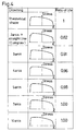
- the contact surface pressure between the inner race 1 and the tapered roller 3 was calculated while variously changing the division number n of the generating line of the raceway surface 1a of the inner race 1 in the embodiment of the invention.
- Fig. 4 shows a result of the calculation.
- the obtained shape is more similar to the theoretical shape A(x) as the division number n, i.e., the number of circular arcs used in the approximation is larger.
- the object of the calculation is to obtain the division number n which is required for attaining a contact surface pressure that is substantially equal to the theoretical shape A(x) in a practical use.
- the generating line shape of the rolling surface of each roller or the raceway surface of the inner or outer race is approximated by a set of circular arcs to a special curve shape such as a logarithmic curve which is derived from the elastic contact theory. Therefore, it is possible to obtain a bearing which can be processed by a usual NC grinding machine, sufficiently used in a practical use, and attain a life period that is substantially equal to that of a bearing of an ideal crowning shape, even when the bearing is used in a portion to which a heavy load or a high torque load is applied.
- the approximation to the special curve shape by a set of circular arcs is performed by an NC grinding machine, and a polishing process is then performed, whereby the generating line shape can be easily made substantially coincide with the special curve shape.
Landscapes
- Engineering & Computer Science (AREA)
- General Engineering & Computer Science (AREA)
- Mechanical Engineering (AREA)
- Rolling Contact Bearings (AREA)
Priority Applications (1)
| Application Number | Priority Date | Filing Date | Title |
|---|---|---|---|
| DE60024344T DE60024344T4 (de) | 1999-03-10 | 2000-03-08 | Rollenlager und ein Herstellungsverfahren desselben |
Applications Claiming Priority (2)
| Application Number | Priority Date | Filing Date | Title |
|---|---|---|---|
| JP6362399 | 1999-03-10 | ||
| JP06362399A JP3757308B2 (ja) | 1999-03-10 | 1999-03-10 | 円錐ころ軸受およびその製造方法 |
Publications (3)
| Publication Number | Publication Date |
|---|---|
| EP1035339A1 true EP1035339A1 (de) | 2000-09-13 |
| EP1035339B1 EP1035339B1 (de) | 2005-11-30 |
| EP1035339B2 EP1035339B2 (de) | 2010-12-22 |
Family
ID=13234655
Family Applications (1)
| Application Number | Title | Priority Date | Filing Date |
|---|---|---|---|
| EP00104882A Expired - Lifetime EP1035339B2 (de) | 1999-03-10 | 2000-03-08 | Rollenlager und ein Herstellungsverfahren desselben |
Country Status (5)
| Country | Link |
|---|---|
| US (1) | US6318897B1 (de) |
| EP (1) | EP1035339B2 (de) |
| JP (1) | JP3757308B2 (de) |
| KR (1) | KR100696244B1 (de) |
| DE (2) | DE60024344T4 (de) |
Cited By (5)
| Publication number | Priority date | Publication date | Assignee | Title |
|---|---|---|---|---|
| WO2007000150A1 (de) * | 2005-06-28 | 2007-01-04 | Schaeffler Kg | Radialwälzlager, insbesondere einreihiges rillen- oder schrägwälzlager |
| DE102005058149A1 (de) * | 2005-12-06 | 2007-07-05 | Schaeffler Kg | Schrägrollenlager mit gekrümmten Laufbahnen |
| EP2025958A4 (de) * | 2006-06-08 | 2010-07-21 | Ntn Toyo Bearing Co Ltd | Rolle und axialrollenlager |
| WO2020035568A1 (de) * | 2018-08-17 | 2020-02-20 | thyssenkrupp rothe erde Germany GmbH | Wälzkörper mit asymmetrischer rollenprofilierung, wälzlager, windkraftanlage und verfahren zur geometrischen dimensionierung von wälzkörpern |
| US11078955B2 (en) * | 2016-04-01 | 2021-08-03 | Ntn Corporation | Tapered roller bearing |
Families Citing this family (19)
| Publication number | Priority date | Publication date | Assignee | Title |
|---|---|---|---|---|
| JP4262851B2 (ja) * | 2000-01-11 | 2009-05-13 | Ntn株式会社 | 車輪軸受装置 |
| JP2002235753A (ja) * | 2001-02-09 | 2002-08-23 | Ntn Corp | シェル型ころ軸受 |
| JP4540893B2 (ja) * | 2001-07-23 | 2010-09-08 | 日本精工株式会社 | 転がり直動案内装置の設計方法及びこれにより設計された転がり直動案内装置 |
| JP2003075328A (ja) * | 2001-09-06 | 2003-03-12 | Koyo Seiko Co Ltd | 軸受用鋼の寿命推定方法 |
| TWI285243B (en) * | 2002-03-20 | 2007-08-11 | Ntn Toyo Bearing Co Ltd | Cylindrical roller bearing |
| JP2005106234A (ja) * | 2003-10-01 | 2005-04-21 | Ntn Corp | 円錐ころ軸受と円錐ころ加工方法 |
| JP4730299B2 (ja) * | 2004-02-19 | 2011-07-20 | 株式会社ジェイテクト | 円錐ころ軸受 |
| CN1942683B (zh) * | 2004-04-14 | 2011-02-02 | 株式会社捷太格特 | 圆锥滚子轴承、圆锥滚子轴承装置、及采用了它的车辆用小齿轮轴支撑装置 |
| JP2007051715A (ja) * | 2005-08-18 | 2007-03-01 | Jtekt Corp | 円錐ころ軸受、円錐ころ軸受装置及びこれを用いた車両用ピニオン軸支持装置 |
| JP5148656B2 (ja) * | 2010-04-30 | 2013-02-20 | 三菱重工業株式会社 | 回転機械 |
| JP6798780B2 (ja) | 2015-01-28 | 2020-12-09 | Ntn株式会社 | 円すいころ軸受 |
| JP2017094404A (ja) * | 2015-11-18 | 2017-06-01 | Ntn株式会社 | 軸受用ころの超仕上げ加工方法および超仕上げ加工装置 |
| JP6838899B2 (ja) * | 2016-09-06 | 2021-03-03 | Ntn株式会社 | 円すいころ軸受 |
| DE102017113933A1 (de) * | 2017-06-23 | 2018-12-27 | Schaeffler Technologies AG & Co. KG | Kegelrollenlager mit korrigierter Lauffläche |
| DE102017120738A1 (de) * | 2017-09-08 | 2019-03-14 | Thyssenkrupp Ag | Wälzlageranordnung und Laufdraht |
| JP6608982B2 (ja) * | 2018-03-28 | 2019-11-20 | Ntn株式会社 | 円錐ころ軸受 |
| CN108747758A (zh) * | 2018-06-12 | 2018-11-06 | 如皋市力星滚子科技有限公司 | 中型圆锥滚子连线 |
| CN111140598A (zh) * | 2020-03-10 | 2020-05-12 | 洛阳Lyc轴承有限公司 | 一种风电设备用调心轴承的修形滚子 |
| CN118057039A (zh) * | 2022-11-18 | 2024-05-21 | 斯凯孚公司 | 低摩擦圆锥滚子轴承及其制造方法 |
Citations (5)
| Publication number | Priority date | Publication date | Assignee | Title |
|---|---|---|---|---|
| DE1163612B (de) * | 1959-11-02 | 1964-02-20 | Kugelfischer G Schaefer & Co | Rollkoerper |
| FR2250915A1 (de) * | 1973-11-12 | 1975-06-06 | Fmc Corp | |
| GB2018912A (en) * | 1978-04-11 | 1979-10-24 | Skf Ab | Rolling bearing |
| FR2533276A1 (fr) * | 1982-09-16 | 1984-03-23 | Torrington Co | Roulement a rouleaux dont les rouleaux sont d'une realisation particuliere |
| US4828404A (en) * | 1988-05-16 | 1989-05-09 | Nippon Seiko Kabushiki Kaisha | Self-aligning roller bearing |
Family Cites Families (4)
| Publication number | Priority date | Publication date | Assignee | Title |
|---|---|---|---|---|
| DE840034C (de) † | 1943-02-18 | 1952-05-26 | Ver Kugellagerfabriken Ag | Rollenlager, insbesondere Ring-Zylinderlager |
| US4877340A (en) | 1988-06-16 | 1989-10-31 | The Timken Company | Process for deriving the contact geometry for raceways and rollers of a roller bearing |
| JP4011677B2 (ja) † | 1997-07-09 | 2007-11-21 | 株式会社ジェイテクト | ころ軸受 |
| JP3731401B2 (ja) † | 1999-08-31 | 2006-01-05 | 日本精工株式会社 | ころ軸受 |
-
1999
- 1999-03-10 JP JP06362399A patent/JP3757308B2/ja not_active Expired - Fee Related
-
2000
- 2000-03-06 US US09/518,883 patent/US6318897B1/en not_active Expired - Lifetime
- 2000-03-08 EP EP00104882A patent/EP1035339B2/de not_active Expired - Lifetime
- 2000-03-08 DE DE60024344T patent/DE60024344T4/de not_active Expired - Lifetime
- 2000-03-08 DE DE60024344A patent/DE60024344D1/de not_active Expired - Lifetime
- 2000-03-10 KR KR1020000011941A patent/KR100696244B1/ko not_active Expired - Fee Related
Patent Citations (5)
| Publication number | Priority date | Publication date | Assignee | Title |
|---|---|---|---|---|
| DE1163612B (de) * | 1959-11-02 | 1964-02-20 | Kugelfischer G Schaefer & Co | Rollkoerper |
| FR2250915A1 (de) * | 1973-11-12 | 1975-06-06 | Fmc Corp | |
| GB2018912A (en) * | 1978-04-11 | 1979-10-24 | Skf Ab | Rolling bearing |
| FR2533276A1 (fr) * | 1982-09-16 | 1984-03-23 | Torrington Co | Roulement a rouleaux dont les rouleaux sont d'une realisation particuliere |
| US4828404A (en) * | 1988-05-16 | 1989-05-09 | Nippon Seiko Kabushiki Kaisha | Self-aligning roller bearing |
Cited By (6)
| Publication number | Priority date | Publication date | Assignee | Title |
|---|---|---|---|---|
| WO2007000150A1 (de) * | 2005-06-28 | 2007-01-04 | Schaeffler Kg | Radialwälzlager, insbesondere einreihiges rillen- oder schrägwälzlager |
| US7828484B2 (en) | 2005-06-28 | 2010-11-09 | Schaeffler Kg | Radial antifriction bearing, particularly a single-row grooved antifriction bearing or angular contact antifriction bearing |
| DE102005058149A1 (de) * | 2005-12-06 | 2007-07-05 | Schaeffler Kg | Schrägrollenlager mit gekrümmten Laufbahnen |
| EP2025958A4 (de) * | 2006-06-08 | 2010-07-21 | Ntn Toyo Bearing Co Ltd | Rolle und axialrollenlager |
| US11078955B2 (en) * | 2016-04-01 | 2021-08-03 | Ntn Corporation | Tapered roller bearing |
| WO2020035568A1 (de) * | 2018-08-17 | 2020-02-20 | thyssenkrupp rothe erde Germany GmbH | Wälzkörper mit asymmetrischer rollenprofilierung, wälzlager, windkraftanlage und verfahren zur geometrischen dimensionierung von wälzkörpern |
Also Published As
| Publication number | Publication date |
|---|---|
| JP3757308B2 (ja) | 2006-03-22 |
| DE60024344T2 (de) | 2006-06-29 |
| EP1035339B2 (de) | 2010-12-22 |
| DE60024344T3 (de) | 2011-09-08 |
| EP1035339B1 (de) | 2005-11-30 |
| KR100696244B1 (ko) | 2007-03-20 |
| DE60024344T4 (de) | 2013-09-12 |
| KR20000062810A (ko) | 2000-10-25 |
| US6318897B1 (en) | 2001-11-20 |
| DE60024344D1 (de) | 2006-01-05 |
| JP2000257637A (ja) | 2000-09-19 |
Similar Documents
| Publication | Publication Date | Title |
|---|---|---|
| US6318897B1 (en) | Roller bearing and a method of producing the same | |
| JP6798780B2 (ja) | 円すいころ軸受 | |
| JPH06246546A (ja) | 転がり軸受の軌道輪製造方法 | |
| JP2005106234A (ja) | 円錐ころ軸受と円錐ころ加工方法 | |
| JP4011677B2 (ja) | ころ軸受 | |
| US10060479B2 (en) | Bearing and method of forming a bearing | |
| JPH09236119A (ja) | スラスト円筒ころ軸受 | |
| KR100774237B1 (ko) | 자동 조심 구름 베어링 및 그 가공 방법 | |
| WO2017014001A1 (ja) | ころ軸受転走面の超仕上げ加工方法 | |
| JP2016138602A (ja) | 円すいころ軸受 | |
| JP2005048881A (ja) | 組合せ軸受、単列軸受、複列軸受の軌道輪の製造方法及び組合せ軸受、単列軸受、複列軸受 | |
| JPH0384218A (ja) | 密封形転がり軸受 | |
| JP4284951B2 (ja) | 玉軸受用軌道輪の製造方法 | |
| JP3774055B2 (ja) | 円すいころ軸受 | |
| JP2007301700A (ja) | 多層構造を有する研削砥石 | |
| JP2006194320A (ja) | ころ軸受の製造方法及びころ軸受 | |
| JP7798192B2 (ja) | 軸受用ころの製造方法 | |
| JPS6028628B2 (ja) | 一体型複列円錐ころ軸受外輪の加工方法 | |
| JPH08210359A (ja) | 転がり軸受 | |
| US20050229372A1 (en) | Method of finishing a metal preform | |
| JP3357619B2 (ja) | センタレス研削方法 | |
| JP2014194244A (ja) | 自動調心ころ軸受 | |
| JPH11277447A (ja) | 超仕上用砥石 | |
| JPH11165249A (ja) | ベルト式研磨装置 | |
| JPH05306719A (ja) | ころがり要素 |
Legal Events
| Date | Code | Title | Description |
|---|---|---|---|
| PUAI | Public reference made under article 153(3) epc to a published international application that has entered the european phase |
Free format text: ORIGINAL CODE: 0009012 |
|
| AK | Designated contracting states |
Kind code of ref document: A1 Designated state(s): DE FR GB IT |
|
| AX | Request for extension of the european patent |
Free format text: AL;LT;LV;MK;RO;SI |
|
| 17P | Request for examination filed |
Effective date: 20000913 |
|
| AKX | Designation fees paid |
Free format text: DE FR GB IT |
|
| 17Q | First examination report despatched |
Effective date: 20040405 |
|
| GRAP | Despatch of communication of intention to grant a patent |
Free format text: ORIGINAL CODE: EPIDOSNIGR1 |
|
| GRAS | Grant fee paid |
Free format text: ORIGINAL CODE: EPIDOSNIGR3 |
|
| GRAA | (expected) grant |
Free format text: ORIGINAL CODE: 0009210 |
|
| AK | Designated contracting states |
Kind code of ref document: B1 Designated state(s): DE FR GB IT |
|
| REG | Reference to a national code |
Ref country code: GB Ref legal event code: FG4D |
|
| REF | Corresponds to: |
Ref document number: 60024344 Country of ref document: DE Date of ref document: 20060105 Kind code of ref document: P |
|
| RAP2 | Party data changed (patent owner data changed or rights of a patent transferred) |
Owner name: JTEKT CORPORATION |
|
| ET | Fr: translation filed | ||
| PLBI | Opposition filed |
Free format text: ORIGINAL CODE: 0009260 |
|
| PLAX | Notice of opposition and request to file observation + time limit sent |
Free format text: ORIGINAL CODE: EPIDOSNOBS2 |
|
| 26 | Opposition filed |
Opponent name: SKF GMBH Effective date: 20060824 |
|
| PLBB | Reply of patent proprietor to notice(s) of opposition received |
Free format text: ORIGINAL CODE: EPIDOSNOBS3 |
|
| PUAH | Patent maintained in amended form |
Free format text: ORIGINAL CODE: 0009272 |
|
| STAA | Information on the status of an ep patent application or granted ep patent |
Free format text: STATUS: PATENT MAINTAINED AS AMENDED |
|
| 27A | Patent maintained in amended form |
Effective date: 20101222 |
|
| AK | Designated contracting states |
Kind code of ref document: B2 Designated state(s): DE FR GB IT |
|
| PGFP | Annual fee paid to national office [announced via postgrant information from national office to epo] |
Ref country code: FR Payment date: 20140311 Year of fee payment: 15 |
|
| REG | Reference to a national code |
Ref country code: FR Ref legal event code: ST Effective date: 20151130 |
|
| PG25 | Lapsed in a contracting state [announced via postgrant information from national office to epo] |
Ref country code: FR Free format text: LAPSE BECAUSE OF NON-PAYMENT OF DUE FEES Effective date: 20150331 |
|
| PGFP | Annual fee paid to national office [announced via postgrant information from national office to epo] |
Ref country code: GB Payment date: 20180307 Year of fee payment: 19 Ref country code: DE Payment date: 20180220 Year of fee payment: 19 |
|
| PGFP | Annual fee paid to national office [announced via postgrant information from national office to epo] |
Ref country code: IT Payment date: 20180321 Year of fee payment: 19 |
|
| REG | Reference to a national code |
Ref country code: DE Ref legal event code: R119 Ref document number: 60024344 Country of ref document: DE |
|
| GBPC | Gb: european patent ceased through non-payment of renewal fee |
Effective date: 20190308 |
|
| PG25 | Lapsed in a contracting state [announced via postgrant information from national office to epo] |
Ref country code: DE Free format text: LAPSE BECAUSE OF NON-PAYMENT OF DUE FEES Effective date: 20191001 Ref country code: GB Free format text: LAPSE BECAUSE OF NON-PAYMENT OF DUE FEES Effective date: 20190308 |
|
| PG25 | Lapsed in a contracting state [announced via postgrant information from national office to epo] |
Ref country code: IT Free format text: LAPSE BECAUSE OF NON-PAYMENT OF DUE FEES Effective date: 20190308 |