EP1031279A2 - Fliehkraftbremse für doppelt gelagerte Angelrollen - Google Patents
Fliehkraftbremse für doppelt gelagerte Angelrollen Download PDFInfo
- Publication number
- EP1031279A2 EP1031279A2 EP00301408A EP00301408A EP1031279A2 EP 1031279 A2 EP1031279 A2 EP 1031279A2 EP 00301408 A EP00301408 A EP 00301408A EP 00301408 A EP00301408 A EP 00301408A EP 1031279 A2 EP1031279 A2 EP 1031279A2
- Authority
- EP
- European Patent Office
- Prior art keywords
- brake
- spool
- housing
- members
- centrifugal
- Prior art date
- Legal status (The legal status is an assumption and is not a legal conclusion. Google has not performed a legal analysis and makes no representation as to the accuracy of the status listed.)
- Granted
Links
- 230000004044 response Effects 0.000 claims abstract description 16
- 230000000717 retained effect Effects 0.000 claims description 6
- 238000006073 displacement reaction Methods 0.000 claims description 3
- 230000007246 mechanism Effects 0.000 abstract description 65
- 210000003813 thumb Anatomy 0.000 description 15
- 238000005266 casting Methods 0.000 description 6
- 238000004804 winding Methods 0.000 description 6
- 210000000078 claw Anatomy 0.000 description 3
- 230000008859 change Effects 0.000 description 2
- 230000003247 decreasing effect Effects 0.000 description 2
- 230000002093 peripheral effect Effects 0.000 description 2
- 239000002131 composite material Substances 0.000 description 1
- 238000010586 diagram Methods 0.000 description 1
- 230000000694 effects Effects 0.000 description 1
- 230000003993 interaction Effects 0.000 description 1
Images


Classifications
-
- A—HUMAN NECESSITIES
- A01—AGRICULTURE; FORESTRY; ANIMAL HUSBANDRY; HUNTING; TRAPPING; FISHING
- A01K—ANIMAL HUSBANDRY; AVICULTURE; APICULTURE; PISCICULTURE; FISHING; REARING OR BREEDING ANIMALS, NOT OTHERWISE PROVIDED FOR; NEW BREEDS OF ANIMALS
- A01K89/00—Reels
- A01K89/015—Reels with a rotary drum, i.e. with a rotating spool
- A01K89/0155—Antibacklash devices
-
- A—HUMAN NECESSITIES
- A01—AGRICULTURE; FORESTRY; ANIMAL HUSBANDRY; HUNTING; TRAPPING; FISHING
- A01K—ANIMAL HUSBANDRY; AVICULTURE; APICULTURE; PISCICULTURE; FISHING; REARING OR BREEDING ANIMALS, NOT OTHERWISE PROVIDED FOR; NEW BREEDS OF ANIMALS
- A01K89/00—Reels
- A01K89/02—Brake devices for reels
- A01K89/033—Brake devices for reels with a rotary drum, i.e. for reels with a rotating spool
-
- A—HUMAN NECESSITIES
- A01—AGRICULTURE; FORESTRY; ANIMAL HUSBANDRY; HUNTING; TRAPPING; FISHING
- A01K—ANIMAL HUSBANDRY; AVICULTURE; APICULTURE; PISCICULTURE; FISHING; REARING OR BREEDING ANIMALS, NOT OTHERWISE PROVIDED FOR; NEW BREEDS OF ANIMALS
- A01K89/00—Reels
- A01K89/015—Reels with a rotary drum, i.e. with a rotating spool
- A01K89/0155—Antibacklash devices
- A01K89/01557—Centrifugal
-
- A—HUMAN NECESSITIES
- A01—AGRICULTURE; FORESTRY; ANIMAL HUSBANDRY; HUNTING; TRAPPING; FISHING
- A01K—ANIMAL HUSBANDRY; AVICULTURE; APICULTURE; PISCICULTURE; FISHING; REARING OR BREEDING ANIMALS, NOT OTHERWISE PROVIDED FOR; NEW BREEDS OF ANIMALS
- A01K89/00—Reels
- A01K89/015—Reels with a rotary drum, i.e. with a rotating spool
- A01K89/01931—Spool or spool shaft details
Definitions
- the present invention relates to a centrifugal braking device. More specifically, the present invention relates to a centrifugal braking device for double bearing reel that is configured for providing braking force to a spool that is rotatably supported in a reel body of a double bearing reel, the centrifugal braking device working in response to centrifugal forces.
- a double bearing reel is mainly used for lure fishing and is also referred to as a bait reel.
- braking force is typically applied to the spool in order to prevent the generation of backlash caused when the rotation speed of a spool exceeds the releasing speed of a fishing line during a casting operation.
- a centrifugal braking device is one braking mechanism used for reducing backlash and is capable of braking the spool using centrifugal forces generated when the spool is rotated.
- centrifugal braking devices include a plurality of brake members and a brake housing.
- the plurality of brake members are provided movably in a radial direction with respect to the spool or a rotating member which rotates together with the spool.
- the brake housing is a member having a cylindrical shape which is fixed to a reel body.
- the brake housing is disposed outside of the brake members so as to be capable of making contact with the brake members.
- centrifugal braking device when the spool rotates, the brake members are urged radially outwardly in centrifugal forces and make contact with a braking surface thereby braking rotation of the spool. Since the centrifugal force increases proportional to the square of the rotation speed of the spool, the generated braking force is not large when the spool rotates at a low speed as, for instance, when winding a fishing line around the spool. However, the generated braking force becomes significantly large when the spool is rotated at high speed as, for instance, during casting out of the fishing line. For this reason, the centrifugal braking device has a characteristic that although resistance generated during a fishing line winding operation is small, a large braking force may be generated when casting a fishing line to prevent backlash.
- the number of brake members which move in the radial direction may be varied in order to adjust the level of the braking force.
- a rocking mechanism is provided with each of the brake members in order to switch the respective brake member from an operating position where the brake member may make contact with the brake housing, to a non-operating position where the brake member does not make contact with the brake housing.
- lure fishing is performed using a bait reel having the above described centrifugal braking device and lures of various weights such as a plug and a worm are used
- the distance that a lure may be cast out varies depending on the weight of the lure.
- the braking force be adjustable in accordance with the weight of the lure.
- Japanese Laid-Open patent application No. 10-304798 discloses a centrifugal braking device in which an adjustment of the braking force may be carried out by touching a dial exposed outside of a reel body.
- the above centrifugal braking device includes a rotating member, a plurality of brake members, a brake housing, and a moving mechanism.
- the rotating member rotates together with the spool.
- the plurality of brake members are movably supported by the rotating member.
- the brake housing is provided on the reel body so as to reciprocate in the spool axis direction.
- the tip of the respective brake members may make contact with the brake housing.
- the moving mechanism includes the rotary dial and it reciprocates the brake housing.
- a contacting portion is formed at a tip of the respective brake member for making contact with the brake housing.
- the brake housing is a disc-shape member provided with a ring-shape brake shoe at its periphery which makes contact with the contacting portion.
- the brake housing reciprocates in the spool axis direction when the dial of the moving mechanism is rotated.
- the brake members are moved radially outwardly with respect to the spool axis when the spool is rotated due to the centrifugal force exerted on the brake members such that the brake members make contact with the brake shoe to brake the spool.
- the braking force may be adjusted by rotating the dial to move the brake housing such that an angle of each respective brake member is varied when it makes contact with the brake shoe.
- the adjustment of the braking force may be easily carried out by rotating the dial in the above conventional centrifugal braking device, a large braking force is hardly obtained since the braking force which is exerted upon making contact with the brake shoe is obtained by the force of the movement of the brake members outwardly in the axial direction. That is, since the brake members move outwardly in the axial direction, not outwardly in the radial direction, it is difficult to efficiently obtain a centrifugal force which acts in the radial direction as a braking force.
- the braking force is adjusted by varying the angle of the respective brake member, the change in the braking force when the brake housing is moved in the spool axis direction is small and, hence, one can hardly feel a distinctive change in the braking force.
- one object of the present invention is to provide a centrifugal braking device for a double bearing reel in which braking force is easily adjusted , a large braking force is obtainable, and distinctive differing levels in braking force are easily selected.
- a centrifugal braking device in a double bearing reel.
- the double bearing reel has a reel housing and a spool rotatably supported within the reel housing.
- the centrifugal braking device provides braking force to the spool in response to centrifugal forces and includes a plurality of circumferentially spaced apart brake members supported within the reel housing for rotation with the spool.
- the brake members are movable in a radially outward direction in response to centrifugal forces.
- Each of the plurality of brake members has a contact portion and each contact portion is located at a different position in an axial direction relative to the spool.
- the centrifugal braking device also includes a brake housing supported in the reel housing.
- the brake housing has a cylindrical shape and is non-rotatable with respect to the reel housing.
- the brake housing is selectively movable in the axial direction relative to the spool such that in a retracted position the brake housing is spaced apart from each of the contact portions such that none of the contact portions is contactable with the brake housing in response to centrifugal forces, and in a non-retracted position at least one of the contact portions is contactable with the brake housing for generating braking force in response to centrifugal forces.
- the centrifugal braking device also includes a means for selectively positioning the brake housing in a plurality of axial positions in the axial direction relative to the spool.
- the centrifugal braking device also includes a rotating member coupled to the spool for rotation therewith.
- the rotating member is formed with means for supporting the plurality of brake members such that at least a portion of each of the brake members is urged radially outward in response to centrifugal forces.
- each of the brake members are supported on a portion of the rotating member for pivotal movement.
- the means for selectively positioning the brake housing includes a rotatable ring member rotatably supported on the reel housing.
- the ring member has a first cam contacting a second cam on the brake housing such that rotation of the rotatable ring member changes the axial position of the brake housing relative to the spool.
- an urging member contacts the brake housing for urging the brake housing in an axial direction away from the rotating member.
- the rotatable ring member is formed with a knob portion that extends in an axial direction, the knob portion extending through an opening in a side cover of the reel housing for operating the means for selectively positioning the brake housing.
- the means for supporting the plurality of brake members on the rotating member includes a plurality of concave portions formed in an axial face of the rotating member proximate a radially outer periphery thereof, a portion of each of the brake members being retained for pivotal movement in the concave portions.
- the means for supporting the plurality of brake members on the rotating member includes a plurality of radially extending shafts fixed to the rotating member, and each of the brake members is disposed on a corresponding one of the shafts such that the brake members may undergo movement in radial directions relative to the spool and the brake members are confined against rotational movement with respect to the shafts.
- the adjustment of the braking force is simple and easy. Also, since a braking of the spool is achieved by moving the brake members radially outward using centrifugal forces, a large braking force may be obtained. Moreover, since the adjustment in the braking force is carried out by changing the number of the contact portions which make contact with the brake housing, the braking force changes in a stepwise manner and a distinctive difference in the braking force may be obtained.
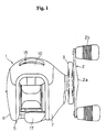
- FIG. 1 is a plan view of a double bearing reel in accordance with one embodiment of the present invention.
- the double bearing reel shown in the FIG. 1 is a bait reel mainly used for a lure fishing and includes a reel body 1, a handle 2, and a star drag 3.
- the handle 2 is provided for rotating a spool and is disposed at one side of the reel body 1.
- the star drag 3 is disposed between the handle 2 and the adjacent side of the reel body 1.
- the handle 2 is of a double handle type which includes an arm portion 2a and holding portions 2b, each of which is rotatably provided with respective end of the arm portion 2a.
- the outer surface of the arm portion 2a of the handle 2 is a smooth jointless surface so that a fishing line is not likely to become entwined around the arm portion 2a.
- the reel body 1 includes a frame 5, a first side cover 6, a second side cover 7, and a front cover 10.
- the first side cover 6 and the second side cover 7 are provided on respective opposite sides of the reel frame 5.
- the front cover 10 is disposed at a front portion of the frame 5 so as to be opened and closed.
- the frame 5 includes a pair of side plates 8 and 9, which are disposed so as to be opposed to each other with a space therebetween, and a plurality of connecting members (not shown) which connect the side plates 8 and 9.
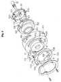
- the brake case 50 has a short cylindrical shape and a bearing accommodating portion 50a that has a cylindrical shape and is formed at a central portion of the brake case 50.
- the bearing 35a for supporting the spool shaft 16 is accommodated in the bearing accommodating portion 50a and a friction plate 22a of the casting control mechanism 22 is attached thereto.
- the rotating member 51 is a disc-shaped member that is connected to the spool shaft 16 by serrations or gear teeth such that the spool shaft 16 and rotating member 51 are not rotatable with respect to one another.
- six concave attachment portions 51a are provided at circumferentially spaced apart locations adjacent to an outer peripheral surface of the rotating member 51.
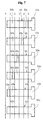
- Each of the concave attachment portions 51a is open in to an axial face of the rotating member 51, as shown in FIGS. 3, 5 and 6.
- Each of the concave attachment portions 51a is an opening having a predetermined axial depth parallel to an axis of rotation of the spool 12.
- a bottom surface of each concave attachment portion 51a having a half-circular shape, as seen in FIG. 5.
- each of the pivoting brake members 53 extends into a corresponding one of the concave attachment portions 51a, with the pivoting brake members 53 retained for pivotal movement within the concave attachment portions 51a.
- a plate 56 is fixed to an axial surface of the rotating member 51, as shown in FIGS. 5 and 6, by a screw shown in FIG. 3.
- the plate 56 is formed with a plurality of circumferential notches or recesses through which a portion of each of the pivoting brake members 53 extends, as shown in FIG. 6.
- the pivoting brake members 53 are retained in the concave attachment portions 51a by the plate 56.
- a radially outward surface of each of the concave attachment portions 51a is inclined radially outward by an angle R1, as shown in FIG. 5.
- the angle R1 is measured with respect to a line that is parallel to the rotational axis of the spool shaft 16.
- the radially inward surface of each of the concave attachment portions 51 is inclined radially inward by an angle R2, as shown in FIG. 5.
- the angle R1 is also measured with respect to a line that is parallel to the rotational axis of the spool shaft 16.
- the inclined radially inward and outward surfaces of each concave attachment portion 51a are provided to limit radial angular inclination of each of the respective pivoting brake members 53.
- the angle R1 is preferably in the range of 3°to 5°and the angle R2 is preferably in the range of 5°to 9°.
- the angle R1 is determined so that the position of a tip end of each of the respective pivoting brake members 53 would extend into the brake liner 57 fixed to inside the brake housing 52. Further, the angle R1 is dimensioned to insure that the pivoting brake members 53 can easily engage the brake liner 57 when the brake liner 57 is moved into position for engagement with the pivoting brake members 53.
- a portion of the surface of the moving portion 53b of each of the pivoting brake members 53 is slightly inclined radially inwardly with respect to the rotational axis of the spool 12 in order to prevent the tip end of each pivoting brake member 53 from contacting the brake liner 57 of the brake housing 52 when the pivoting brake member 53 is urged radially outwardly.
- only the contact portion 53c makes contact with the brake liner 57 of the brake housing 52 in order to provide a braking force to the spool 12.
- the brake housing 52 includes an inner portion 52a, an outer portion 52b, and a middle portion 52c.
- the end of the brake liner 57 has a tapered surface 57a so as make an increase in height from an inner radial inner side to an outer radial side more gradual, as shown in FIG. 3.
- the pivoting brake members 53 are smoothly guided to the inner side of the brake liner 57 due to the presence of the tapered surface 57a.
- the cam mechanism 71 converts the rotational movement of the rotatable ring member 70 to axial movement of the brake liner 57 in a manner described in greater detail below.
- the returning spring 72 urges the brake housing 52 axially outward against the cam mechanism 71.
- the projecting portion 70c becomes aligned with numbers 0 through 5 (not shown) printed on the surface of the first side cover 6 adjacent to the oblong opening to provide an indication of the position of the rotatable ring member 70 thereby indicating the strength of braking force applied to the spool 12.
- a pair of rotation controlling concave portions 70b are formed on a radially inner periphery of the rotatable ring member 70 for limiting rotational movement of the rotatable ring member 70 with respect to the brake case 50.
- the rotatable ring member 70 is compressed against the brake case 50 by a pressing plate 75.
- the pressing plate 75 compresses the rotatable ring member 70 by means of screws, each of which is tighten against a respective screw base portion 50d formed on the outer side surface of the brake case 50.
- the screw base portion 50d protrudes radially outward.
- the range of the rotational angle of the rotatable ring member 70 is predetermined by the screw base portions 50d which stops the movement of the rotatable ring member 70 by contacting surfaces of respective rotation controlling concave portions 70b.
- the number of pivoting brake members 53 that are able to contact with the brake liner 57 is decreased and the braking force is reduced since the brake housing 52 is moved away from the rotating member 51 due to an urging force of the returning spring 72.
- the brake liner 57 moves to a position where all of the contact portions 53c on the pivoting brake members 53 are spaced apart from the brake liner 57, no braking force is exerted.
- the clutch chalk 40 is pressed inwardly and, hence, a clutch-on state is attained and the spool 12 can be rotated by rotation of the handle 2.
- rotational force applied to the handle 2 is transmitted to the spool 12 via the handle shaft 30, the main gear 31, the pinion gear 32 and the spool shaft 16 to rotate the spool 12 in the line-winding direction.
- centrifugal forces are exerted on the pivoting brake members 53 of the centrifugal braking mechanism 23 to move the pivoting brake members 53 radially outwardly.
- the brake housing 52 may be positioned at position 0 by rotating the rotatable ring member 70 in the direction indicated by the arrow B in FIG. 4 using the knob portion 70a.
- the brake liner 57 is positioned such that none of the pivoting brake members 53 are able to make contact with the brake liner 57 and there is no braking force by the centrifugal braking mechanism 23 is exerted on the spool 12.
- the user rotates the handle in order to engage the clutch mechanism 13 and rotate the spool 12 thereby winding in the fishing line.
- the thumb rest 17 is movable in a downward direction (with respect to FIGS. 1 and 2) in order to dis-engage the clutch mechanism 13. Due to the movement of the thumb rest 17, the clutch chalk 40 and the pinion gear 32 are moved outwardly to dis-engage the clutch mechanism 13. In the dis-engaged state, the rotation from the handle shaft 30 is not transmitted to neither the spool 12 nor the spool shaft 16 and the spool 12 may freely rotate.
- the spool shaft 16 is rotated in the line-releasing direction by the rotation of the spool 12, and the rotation is transmitted to the rotating member 51.
- the pivoting brake members 53 make contact with the brake liner 57 and the spool 12 is braked by the centrifugal braking mechanism 23 to prevent a generation of backlash.
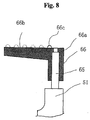
- Each of the sliding brake members 66 includes a guiding portion 66a, a brake portion 66b, and one contact portion 66c.
- the guiding portion 66a has a cylindrical shape and is fitted onto the respective guiding shaft 65.
- the brake portion 66b extends in the axial direction from the guiding portion 66a.
- the contact portion 66c is disposed on the outer surface of the brake portion 66b and extends radially outward. As in the above-mentioned embodiment in FIGS. 1-7, there is only one contact portion 66c formed on any single sliding brake member 66. However, as indicated in phantom lines in FIG. 8, each contact portion 66c is located at a different position in the axial direction relative to the rotational axis of the spool 12.
- the alternate embodiment in FIG. 8 is such that as the brake liner 57 is adjustably moved toward the rotating member 51, the level of braking force may be increased in a step-wise fashion as, one by one, the various contact portions 66c are able to contact the brake liner 57.
- the adjustment of the braking force is easy since the number of the sliding brake members 66 which are able to make contact with the brake liner 57 is readily changeable by operating the adjusting mechanism 55 in the same manner as in the first embodiment (in FIGS. 1-7). Also, a large braking force is obtainable since the sliding brake members 66 are moved radially outwardly by the centrifugal forces. Moreover, a distinctive difference in the braking force may be obtained by the adjustment since the braking force is adjusted stepwise by changing the number of the contact portions 66c which make contact with the brake liner 57.
- the adjustment of the braking force may be easily carried out since the number of the pivoting brake members which are able to make contact with the braking liner is readily varied by operating the moving mechanism. Also, a large braking force is obtained since the pivoting brake members are moved outwardly in the radial direction by the centrifugal forces. Moreover, a distinctive difference in the braking force may be obtained by an adjustment since the braking force is adjusted stepwise by changing the number of the contacting portions which make contact with the braking liner.
Landscapes
- Life Sciences & Earth Sciences (AREA)
- Environmental Sciences (AREA)
- Animal Husbandry (AREA)
- Biodiversity & Conservation Biology (AREA)
- Braking Arrangements (AREA)
Applications Claiming Priority (2)
| Application Number | Priority Date | Filing Date | Title |
|---|---|---|---|
| JP4770599 | 1999-02-25 | ||
| JP11047705A JP2000245314A (ja) | 1999-02-25 | 1999-02-25 | 両軸受リールの遠心制動装置 |
Publications (3)
| Publication Number | Publication Date |
|---|---|
| EP1031279A2 true EP1031279A2 (de) | 2000-08-30 |
| EP1031279A3 EP1031279A3 (de) | 2000-09-13 |
| EP1031279B1 EP1031279B1 (de) | 2003-07-23 |
Family
ID=12782727
Family Applications (1)
| Application Number | Title | Priority Date | Filing Date |
|---|---|---|---|
| EP00301408A Expired - Lifetime EP1031279B1 (de) | 1999-02-25 | 2000-02-23 | Fliehkraftbremse für doppelt gelagerte Angelrollen |
Country Status (8)
| Country | Link |
|---|---|
| US (1) | US6254021B1 (de) |
| EP (1) | EP1031279B1 (de) |
| JP (1) | JP2000245314A (de) |
| KR (1) | KR100616144B1 (de) |
| AT (1) | ATE245347T1 (de) |
| DE (1) | DE60003960T2 (de) |
| ES (1) | ES2202002T3 (de) |
| TW (1) | TW442258B (de) |
Cited By (3)
| Publication number | Priority date | Publication date | Assignee | Title |
|---|---|---|---|---|
| EP1072191A3 (de) * | 1999-07-26 | 2002-04-10 | Shimano Inc. | Fliehkraftbremse für doppelt gelagerte Angelrollen |
| KR100616144B1 (ko) * | 1999-02-25 | 2006-08-25 | 가부시키가이샤 시마노 | 양 베어링 릴의 원심제동장치 |
| CN109092575A (zh) * | 2018-09-19 | 2018-12-28 | 中国工程物理研究院总体工程研究所 | 基于回转中心位置调整的离心机配平装置及方法 |
Families Citing this family (20)
| Publication number | Priority date | Publication date | Assignee | Title |
|---|---|---|---|---|
| JP4313902B2 (ja) * | 1999-08-04 | 2009-08-12 | 株式会社シマノ | 両軸受リールの遠心制動装置 |
| JP2001054342A (ja) * | 1999-08-13 | 2001-02-27 | Shimano Inc | 両軸受リールの遠心制動装置 |
| JP3535781B2 (ja) * | 1999-10-28 | 2004-06-07 | ダイワ精工株式会社 | 魚釣用リ−ル |
| US6530535B2 (en) * | 2000-03-16 | 2003-03-11 | Daiwa Seiko, Inc. | Fishing reel |
| JP4321064B2 (ja) | 2001-03-05 | 2009-08-26 | 株式会社ニコン | 画像処理装置および画像処理プログラム |
| KR100451886B1 (ko) * | 2002-09-12 | 2004-10-08 | 주식회사 바낙스 | 베이트케스트 릴의 원심 브레이크 장치 |
| SE0300372L (sv) * | 2003-02-12 | 2003-11-25 | Pure Fishing Inc | Fiskerulle av multiplikatortyp |
| JP5350881B2 (ja) * | 2009-05-15 | 2013-11-27 | 株式会社シマノ | 両軸受リールのスプール制動装置 |
| JP5718119B2 (ja) * | 2011-03-29 | 2015-05-13 | 株式会社シマノ | 両軸受リールの遠心制動装置 |
| JP5926564B2 (ja) | 2012-01-18 | 2016-05-25 | 株式会社シマノ | 両軸受リールのスプール制動装置及び両軸受リール |
| JP6177550B2 (ja) * | 2013-03-15 | 2017-08-09 | 株式会社シマノ | 両軸受リールのスプール制動装置及び両軸受リール |
| JP6412680B2 (ja) * | 2013-04-26 | 2018-10-24 | 株式会社シマノ | 両軸受リール |
| JP6295033B2 (ja) * | 2013-06-25 | 2018-03-14 | 株式会社シマノ | 両軸受リールのスプール制動装置及び両軸受リール |
| KR101510729B1 (ko) * | 2013-07-09 | 2015-04-10 | 유한책임회사 도요엔지니어링 | 정밀 원심 제동시스템을 구비한 낚시릴 |
| KR101744597B1 (ko) * | 2015-11-23 | 2017-06-20 | 주식회사 코커스 | 낚시용 릴 |
| SE1650201A1 (en) * | 2016-02-16 | 2017-06-13 | Brillianze Sweden Ab | Rotational friction brake regulated by angular acceleration |
| JP7049940B2 (ja) * | 2018-06-21 | 2022-04-07 | 株式会社シマノ | 両軸受リール |
| JP7578436B2 (ja) * | 2020-08-27 | 2024-11-06 | グローブライド株式会社 | 魚釣用リール、その制動装置及び制動システム |
| KR20220027735A (ko) * | 2020-08-27 | 2022-03-08 | 글로브라이드 가부시키가이샤 | 낚시 정보 관리 시스템 및 처리 방법 |
| US11864543B2 (en) * | 2021-01-25 | 2024-01-09 | Cary Hogan JONES | Fly fishing reel with brake assembly and methods |
Citations (1)
| Publication number | Priority date | Publication date | Assignee | Title |
|---|---|---|---|---|
| JPH10304798A (ja) | 1997-03-06 | 1998-11-17 | Ryobi Ltd | 両軸受けリールの遠心制動装置 |
Family Cites Families (10)
| Publication number | Priority date | Publication date | Assignee | Title |
|---|---|---|---|---|
| JP2538904Y2 (ja) | 1991-07-10 | 1997-06-18 | 株式会社シマノ | 釣り用リールの遠心ブレーキ機構 |
| US5362011A (en) * | 1991-12-16 | 1994-11-08 | Shimano Inc. | Baitcasting reel having an improved centrifugal brake |
| JP2572095Y2 (ja) * | 1992-01-28 | 1998-05-20 | 株式会社シマノ | 両軸受リール |
| JP3159625B2 (ja) | 1995-05-24 | 2001-04-23 | ダイワ精工株式会社 | 魚釣用リールの制動装置 |
| US5803385A (en) * | 1996-10-16 | 1998-09-08 | Penn Fishing Tackle Manufacturing Company | Centrifugal brake system for fishing reel |
| US5996921A (en) * | 1997-03-06 | 1999-12-07 | Ryobi Limited | Centrifugal braking apparatus for baitcasting reel |
| US5950949A (en) | 1997-04-25 | 1999-09-14 | Zebco Division Of Brunswick Corporation | Adjustable brake for baitcast reel |
| JP3509535B2 (ja) * | 1998-03-10 | 2004-03-22 | ダイワ精工株式会社 | 魚釣用両軸受型リール |
| US5984221A (en) * | 1998-10-21 | 1999-11-16 | Zebco Division Of Brunswick Corporation | Adjustable brake for baitcast reel |
| JP2000245314A (ja) * | 1999-02-25 | 2000-09-12 | Shimano Inc | 両軸受リールの遠心制動装置 |
-
1999
- 1999-02-25 JP JP11047705A patent/JP2000245314A/ja active Pending
-
2000
- 2000-02-22 US US09/510,342 patent/US6254021B1/en not_active Expired - Lifetime
- 2000-02-23 DE DE60003960T patent/DE60003960T2/de not_active Expired - Fee Related
- 2000-02-23 EP EP00301408A patent/EP1031279B1/de not_active Expired - Lifetime
- 2000-02-23 ES ES00301408T patent/ES2202002T3/es not_active Expired - Lifetime
- 2000-02-23 AT AT00301408T patent/ATE245347T1/de not_active IP Right Cessation
- 2000-02-24 KR KR1020000009035A patent/KR100616144B1/ko not_active Expired - Fee Related
- 2000-02-25 TW TW089103421A patent/TW442258B/zh active
Patent Citations (1)
| Publication number | Priority date | Publication date | Assignee | Title |
|---|---|---|---|---|
| JPH10304798A (ja) | 1997-03-06 | 1998-11-17 | Ryobi Ltd | 両軸受けリールの遠心制動装置 |
Cited By (4)
| Publication number | Priority date | Publication date | Assignee | Title |
|---|---|---|---|---|
| KR100616144B1 (ko) * | 1999-02-25 | 2006-08-25 | 가부시키가이샤 시마노 | 양 베어링 릴의 원심제동장치 |
| EP1072191A3 (de) * | 1999-07-26 | 2002-04-10 | Shimano Inc. | Fliehkraftbremse für doppelt gelagerte Angelrollen |
| CN109092575A (zh) * | 2018-09-19 | 2018-12-28 | 中国工程物理研究院总体工程研究所 | 基于回转中心位置调整的离心机配平装置及方法 |
| CN109092575B (zh) * | 2018-09-19 | 2024-01-30 | 中国工程物理研究院总体工程研究所 | 基于回转中心位置调整的离心机配平装置及方法 |
Also Published As
| Publication number | Publication date |
|---|---|
| JP2000245314A (ja) | 2000-09-12 |
| ATE245347T1 (de) | 2003-08-15 |
| DE60003960T2 (de) | 2004-04-22 |
| DE60003960D1 (de) | 2003-08-28 |
| ES2202002T3 (es) | 2004-04-01 |
| US6254021B1 (en) | 2001-07-03 |
| KR100616144B1 (ko) | 2006-08-25 |
| TW442258B (en) | 2001-06-23 |
| EP1031279A3 (de) | 2000-09-13 |
| KR20000076723A (ko) | 2000-12-26 |
| EP1031279B1 (de) | 2003-07-23 |
Similar Documents
| Publication | Publication Date | Title |
|---|---|---|
| EP1031279B1 (de) | Fliehkraftbremse für doppelt gelagerte Angelrollen | |
| US9439408B2 (en) | Dual-bearing reel | |
| KR100338543B1 (ko) | 분리백래시제어를 구비한 낚시용 베이트케스팅 릴 | |
| JP6177550B2 (ja) | 両軸受リールのスプール制動装置及び両軸受リール | |
| US5921492A (en) | Large arbor fishing reel embodying recessed drag control knob and zero backlash drag engagement clutch | |
| US6371396B1 (en) | Dual-bearing reel braking device | |
| JP2014176360A5 (de) | ||
| US6364230B1 (en) | Dual-bearing reel centrifugal braking device | |
| JP2017148027A (ja) | 両軸受リール | |
| KR101217155B1 (ko) | 듀얼 베어링 릴의 스풀 | |
| US6196485B1 (en) | Dual-bearing reel centrifugal braking device | |
| US5277379A (en) | Spinning reel for fishing | |
| KR20010067073A (ko) | 베이트 캐스트 릴용 자기 위치 조절 가능한 브레이크 | |
| JP6284306B2 (ja) | 両軸受リールのスプール制動装置 | |
| JP2014217341A5 (de) | ||
| TWI624224B (zh) | Double bearing reel reel brake device and double bearing reel | |
| JP2002084939A (ja) | 無限制御を備えた投げ餌釣りリール用調節自在制動機 | |
| JP3747429B2 (ja) | 両軸受リールの制動装置 | |
| US6908054B1 (en) | Internally adjustable brake for baitcast reel | |
| JP6267874B2 (ja) | 両軸受リールのスプール制動装置 | |
| JP3747430B2 (ja) | 両軸受リールの遠心制動装置 | |
| JP2001095443A (ja) | 両軸受リールの遠心制動装置 | |
| JP2003079292A (ja) | 両軸受リールのスプール制動装置 | |
| KR0131874Y1 (ko) | 베이트 캐스팅릴의 스풀회전력 조절장치 | |
| JP3797832B2 (ja) | 両軸受リールの遠心制動装置 |
Legal Events
| Date | Code | Title | Description |
|---|---|---|---|
| PUAI | Public reference made under article 153(3) epc to a published international application that has entered the european phase |
Free format text: ORIGINAL CODE: 0009012 |
|
| PUAL | Search report despatched |
Free format text: ORIGINAL CODE: 0009013 |
|
| AK | Designated contracting states |
Kind code of ref document: A2 Designated state(s): AT BE CH CY DE DK ES FI FR GB GR IE IT LI LU MC NL PT SE |
|
| AX | Request for extension of the european patent |
Free format text: AL;LT;LV;MK;RO;SI |
|
| AK | Designated contracting states |
Kind code of ref document: A3 Designated state(s): AT BE CH CY DE DK ES FI FR GB GR IE IT LI LU MC NL PT SE |
|
| AX | Request for extension of the european patent |
Free format text: AL;LT;LV;MK;RO;SI |
|
| RIN1 | Information on inventor provided before grant (corrected) |
Inventor name: MORIMOTO, SHIN'ICHI Inventor name: KAWASAKI, KEN'ICHI |
|
| 17P | Request for examination filed |
Effective date: 20010207 |
|
| AKX | Designation fees paid |
Free format text: AT BE CH CY DE DK ES FI FR GB GR IE IT LI LU MC NL PT SE |
|
| GRAH | Despatch of communication of intention to grant a patent |
Free format text: ORIGINAL CODE: EPIDOS IGRA |
|
| GRAA | (expected) grant |
Free format text: ORIGINAL CODE: 0009210 |
|
| GRAH | Despatch of communication of intention to grant a patent |
Free format text: ORIGINAL CODE: EPIDOS IGRA |
|
| AK | Designated contracting states |
Designated state(s): AT BE CH CY DE DK ES FI FR GB GR IE IT LI LU MC NL PT SE |
|
| PG25 | Lapsed in a contracting state [announced via postgrant information from national office to epo] |
Ref country code: LI Free format text: LAPSE BECAUSE OF FAILURE TO SUBMIT A TRANSLATION OF THE DESCRIPTION OR TO PAY THE FEE WITHIN THE PRESCRIBED TIME-LIMIT Effective date: 20030723 Ref country code: CY Free format text: LAPSE BECAUSE OF FAILURE TO SUBMIT A TRANSLATION OF THE DESCRIPTION OR TO PAY THE FEE WITHIN THE PRESCRIBED TIME-LIMIT Effective date: 20030723 Ref country code: CH Free format text: LAPSE BECAUSE OF FAILURE TO SUBMIT A TRANSLATION OF THE DESCRIPTION OR TO PAY THE FEE WITHIN THE PRESCRIBED TIME-LIMIT Effective date: 20030723 Ref country code: FI Free format text: LAPSE BECAUSE OF FAILURE TO SUBMIT A TRANSLATION OF THE DESCRIPTION OR TO PAY THE FEE WITHIN THE PRESCRIBED TIME-LIMIT Effective date: 20030723 |
|
| REG | Reference to a national code |
Ref country code: GB Ref legal event code: FG4D |
|
| REG | Reference to a national code |
Ref country code: CH Ref legal event code: EP |
|
| REG | Reference to a national code |
Ref country code: IE Ref legal event code: FG4D |
|
| REF | Corresponds to: |
Ref document number: 60003960 Country of ref document: DE Date of ref document: 20030828 Kind code of ref document: P |
|
| PG25 | Lapsed in a contracting state [announced via postgrant information from national office to epo] |
Ref country code: DK Free format text: LAPSE BECAUSE OF FAILURE TO SUBMIT A TRANSLATION OF THE DESCRIPTION OR TO PAY THE FEE WITHIN THE PRESCRIBED TIME-LIMIT Effective date: 20031023 Ref country code: GR Free format text: LAPSE BECAUSE OF FAILURE TO SUBMIT A TRANSLATION OF THE DESCRIPTION OR TO PAY THE FEE WITHIN THE PRESCRIBED TIME-LIMIT Effective date: 20031023 |
|
| REG | Reference to a national code |
Ref country code: SE Ref legal event code: TRGR |
|
| PG25 | Lapsed in a contracting state [announced via postgrant information from national office to epo] |
Ref country code: PT Free format text: LAPSE BECAUSE OF FAILURE TO SUBMIT A TRANSLATION OF THE DESCRIPTION OR TO PAY THE FEE WITHIN THE PRESCRIBED TIME-LIMIT Effective date: 20031223 |
|
| PGFP | Annual fee paid to national office [announced via postgrant information from national office to epo] |
Ref country code: NL Payment date: 20040205 Year of fee payment: 5 |
|
| PGFP | Annual fee paid to national office [announced via postgrant information from national office to epo] |
Ref country code: AT Payment date: 20040211 Year of fee payment: 5 |
|
| REG | Reference to a national code |
Ref country code: CH Ref legal event code: PL |
|
| PG25 | Lapsed in a contracting state [announced via postgrant information from national office to epo] |
Ref country code: LU Free format text: LAPSE BECAUSE OF NON-PAYMENT OF DUE FEES Effective date: 20040223 Ref country code: IE Free format text: LAPSE BECAUSE OF NON-PAYMENT OF DUE FEES Effective date: 20040223 |
|
| PGFP | Annual fee paid to national office [announced via postgrant information from national office to epo] |
Ref country code: ES Payment date: 20040227 Year of fee payment: 5 |
|
| PG25 | Lapsed in a contracting state [announced via postgrant information from national office to epo] |
Ref country code: MC Free format text: LAPSE BECAUSE OF NON-PAYMENT OF DUE FEES Effective date: 20040228 |
|
| REG | Reference to a national code |
Ref country code: ES Ref legal event code: FG2A Ref document number: 2202002 Country of ref document: ES Kind code of ref document: T3 |
|
| PGFP | Annual fee paid to national office [announced via postgrant information from national office to epo] |
Ref country code: BE Payment date: 20040506 Year of fee payment: 5 |
|
| ET | Fr: translation filed | ||
| PLBE | No opposition filed within time limit |
Free format text: ORIGINAL CODE: 0009261 |
|
| STAA | Information on the status of an ep patent application or granted ep patent |
Free format text: STATUS: NO OPPOSITION FILED WITHIN TIME LIMIT |
|
| 26N | No opposition filed |
Effective date: 20040426 |
|
| REG | Reference to a national code |
Ref country code: IE Ref legal event code: MM4A |
|
| PGFP | Annual fee paid to national office [announced via postgrant information from national office to epo] |
Ref country code: SE Payment date: 20050204 Year of fee payment: 6 |
|
| PGFP | Annual fee paid to national office [announced via postgrant information from national office to epo] |
Ref country code: FR Payment date: 20050208 Year of fee payment: 6 |
|
| PG25 | Lapsed in a contracting state [announced via postgrant information from national office to epo] |
Ref country code: AT Free format text: LAPSE BECAUSE OF NON-PAYMENT OF DUE FEES Effective date: 20050223 |
|
| PG25 | Lapsed in a contracting state [announced via postgrant information from national office to epo] |
Ref country code: ES Free format text: LAPSE BECAUSE OF NON-PAYMENT OF DUE FEES Effective date: 20050224 |
|
| PG25 | Lapsed in a contracting state [announced via postgrant information from national office to epo] |
Ref country code: BE Free format text: LAPSE BECAUSE OF NON-PAYMENT OF DUE FEES Effective date: 20050228 |
|
| BERE | Be: lapsed |
Owner name: *SHIMANO INC. Effective date: 20050228 |
|
| PG25 | Lapsed in a contracting state [announced via postgrant information from national office to epo] |
Ref country code: NL Free format text: LAPSE BECAUSE OF NON-PAYMENT OF DUE FEES Effective date: 20050901 |
|
| NLV4 | Nl: lapsed or anulled due to non-payment of the annual fee |
Effective date: 20050901 |
|
| PG25 | Lapsed in a contracting state [announced via postgrant information from national office to epo] |
Ref country code: SE Free format text: LAPSE BECAUSE OF NON-PAYMENT OF DUE FEES Effective date: 20060224 |
|
| REG | Reference to a national code |
Ref country code: ES Ref legal event code: FD2A Effective date: 20050224 |
|
| EUG | Se: european patent has lapsed | ||
| REG | Reference to a national code |
Ref country code: FR Ref legal event code: ST Effective date: 20061031 |
|
| BERE | Be: lapsed |
Owner name: *SHIMANO INC. Effective date: 20050228 |
|
| PG25 | Lapsed in a contracting state [announced via postgrant information from national office to epo] |
Ref country code: FR Free format text: LAPSE BECAUSE OF NON-PAYMENT OF DUE FEES Effective date: 20060228 |
|
| PGFP | Annual fee paid to national office [announced via postgrant information from national office to epo] |
Ref country code: DE Payment date: 20080221 Year of fee payment: 9 Ref country code: GB Payment date: 20080220 Year of fee payment: 9 Ref country code: IT Payment date: 20080227 Year of fee payment: 9 |
|
| GBPC | Gb: european patent ceased through non-payment of renewal fee |
Effective date: 20090223 |
|
| PG25 | Lapsed in a contracting state [announced via postgrant information from national office to epo] |
Ref country code: DE Free format text: LAPSE BECAUSE OF NON-PAYMENT OF DUE FEES Effective date: 20090901 |
|
| PG25 | Lapsed in a contracting state [announced via postgrant information from national office to epo] |
Ref country code: GB Free format text: LAPSE BECAUSE OF NON-PAYMENT OF DUE FEES Effective date: 20090223 |
|
| PG25 | Lapsed in a contracting state [announced via postgrant information from national office to epo] |
Ref country code: IT Free format text: LAPSE BECAUSE OF NON-PAYMENT OF DUE FEES Effective date: 20090223 |