EP1026060A2 - Bremssystem - Google Patents
Bremssystem Download PDFInfo
- Publication number
- EP1026060A2 EP1026060A2 EP00102059A EP00102059A EP1026060A2 EP 1026060 A2 EP1026060 A2 EP 1026060A2 EP 00102059 A EP00102059 A EP 00102059A EP 00102059 A EP00102059 A EP 00102059A EP 1026060 A2 EP1026060 A2 EP 1026060A2
- Authority
- EP
- European Patent Office
- Prior art keywords
- brake
- electrically controlled
- electric power
- braking system
- actuator
- Prior art date
- Legal status (The legal status is an assumption and is not a legal conclusion. Google has not performed a legal analysis and makes no representation as to the accuracy of the status listed.)
- Withdrawn
Links
Images


Classifications
-
- B—PERFORMING OPERATIONS; TRANSPORTING
- B60—VEHICLES IN GENERAL
- B60T—VEHICLE BRAKE CONTROL SYSTEMS OR PARTS THEREOF; BRAKE CONTROL SYSTEMS OR PARTS THEREOF, IN GENERAL; ARRANGEMENT OF BRAKING ELEMENTS ON VEHICLES IN GENERAL; PORTABLE DEVICES FOR PREVENTING UNWANTED MOVEMENT OF VEHICLES; VEHICLE MODIFICATIONS TO FACILITATE COOLING OF BRAKES
- B60T13/00—Transmitting braking action from initiating means to ultimate brake actuator with power assistance or drive; Brake systems incorporating such transmitting means, e.g. air-pressure brake systems
- B60T13/74—Transmitting braking action from initiating means to ultimate brake actuator with power assistance or drive; Brake systems incorporating such transmitting means, e.g. air-pressure brake systems with electrical assistance or drive
- B60T13/741—Transmitting braking action from initiating means to ultimate brake actuator with power assistance or drive; Brake systems incorporating such transmitting means, e.g. air-pressure brake systems with electrical assistance or drive acting on an ultimate actuator
-
- B—PERFORMING OPERATIONS; TRANSPORTING
- B60—VEHICLES IN GENERAL
- B60T—VEHICLE BRAKE CONTROL SYSTEMS OR PARTS THEREOF; BRAKE CONTROL SYSTEMS OR PARTS THEREOF, IN GENERAL; ARRANGEMENT OF BRAKING ELEMENTS ON VEHICLES IN GENERAL; PORTABLE DEVICES FOR PREVENTING UNWANTED MOVEMENT OF VEHICLES; VEHICLE MODIFICATIONS TO FACILITATE COOLING OF BRAKES
- B60T2220/00—Monitoring, detecting driver behaviour; Signalling thereof; Counteracting thereof
- B60T2220/04—Pedal travel sensor, stroke sensor; Sensing brake request
Definitions
- the present invention relates to an electrically controlled braking system including a brake control apparatus which is adapted to control a brake by controlling an electric energy supplied thereto from an electric power source.
- JP-A-5-158742 discloses an example of such an electrically controlled braking system including a brake for braking a wheel of an automotive vehicle, an electric power source, and a brake control apparatus for controlling the brake by controlling an electric energy supplied thereto from the electric power source.
- the brake is actuated by a pressurized working fluid
- the brake control apparatus includes a solenoid-operated valve device, and a control portion constituted principally by a computer, which is adapted to control an electric energy to be supplied to a solenoid coil of the solenoid-operated valve device so that an operation of the brake is controlled.
- an electric power source switch is provided between the electric power source and the solenoid-operated valve device.
- This electric power source switch is turned from an OFF state to an ON state when an ignition switch of the vehicle is turned on. Therefore, this electrically controlled braking system suffers from a problem that the brake is not activated by an operation of a brake operating member while the ignition switch is off. Accordingly, the braking system is necessarily arranged such that a manually operated brake is activated while the ignition switch is in the off state. This arrangement suffers from another problem that the braking force produced by the brake changes when the ignition switch is turned on or off while the brake operating member is placed in an operated position.
- the electrically controlled braking system changes from an operated state to a non-operated state, causing a change in the braking force, which may make the vehicle operator feel uneasy about the braking system.
- the solenoid-operated valve device may be inoperable in the case of an excessive drop of the output of the single electric power source, or in the event of occurrence of any abnormality of an electric circuit connecting the solenoid-operated valve device and the electric power source.
- electrically controlled braking system is interpreted to mean not only a braking system of the type described above, but also a braking system of a type wherein the brake includes an electrically operated actuator adapted to force a friction member onto a rotor so that the wheel rotating with the rotor is braked, while the brake control apparatus includes an actuator control device for controlling the electric energy to be supplied to the electrically operated actuator from the electric power source device, so as to control an operation of the brake.
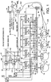
- the electrically controlled braking system shown therein has four electrically brakes 10, 12, 14, 16 for respective front left and right wheels FL, FR and rear left and right wheels RL, RR, and a brake control apparatus 18 for controlling operations of these brakes 10, 12, 14, 16.
- the brakes 10 and 12 for the front wheels FL, FR are disc brakes including respective electric motors 22, 24.
- Each of the disc brakes 10, 12 has friction pads which are forced onto a brake disc so that the corresponding front wheel FL, FR rotating with the brake disc is braked.
- the brakes 14, 16 are drum brakes including respective electric motors 30, 32.
- Each of the drum brakes 14, 16 has brake linings which are forced onto a brake drum so that the corresponding rear wheel rotating with the brake drum is braked.
- the rear left and right wheels RL, RR are also provided with respective electrically operated parking brakes 33, 34, which are both operated by a electric motor 36 upon operation of respective parking brake switches 35.
- the parking brakes 33, 34 may be operated by operation of a brake operating member in the form of a brake pedal 38.
- the electric motors 22, 24, 30, 32, 36 are controlled by the brake control apparatus 18, which includes a main control device 42, five motor control devices (electronic control units: ECUs) 44, 46, 48, 50, 52 for controlling the respective electric motors 22, 23, 30, 32, 36, and five motor driver circuits 54, 56, 58, 60, 62 for driving the respective drive motors 22, 23, 30, 32, 36.
- the electric motors 22, 24, 30, 32, 36 are operated by an electric energy supplied from at least one of two electric power sources in the form of batteries 64, 66.
- the two batteries 64, 66 cooperate to serve as an electric power source device.
- the main control device 42 includes a first control device 68 and a second control device 70.
- the two batteries 64, 66 are operated by an alternator 72, to store therein electric energies.
- the battery 64 stores the electric energy of 12V
- the battery 66 stores the electric energy of 36V.
- an electric circuit 73 including the battery 64 there are connected in parallel with each other: a group of control devices consisting of the first control device 68, the motor control devices 44, 46 and driver circuits 54, 56 for the front disc brakes 10, 12, the motor control device 48 and driver circuit 58 for the rear left drum brake 14, and the motor control device 52 and driver circuit 62 for the parking brakes 33, 34; a group of 12V electric motors consisting of the electric motor 30 for the rear left drum brake 14, and the electric motor 36 for the parking brakes 33, 34); and a group of 36V electric motors consisting of the electric motors 22, 24 for the front disc brakes 10, 12.
- the first control device 68 and the motor control devices 44, 46, 48, 52 of the above-indicted group of control devices are connected in parallel with each other.
- the electric motors 30, 36 are connected in parallel with each other.
- the electric motors 22, 24 are connected in parallel with each other. Accordingly, the first control device 68, motor control devices 44, 46, driver circuits 54, 56, motor control device 48, driver circuit 58, motor control device 52, driver circuit 62, and electric motors 30, 36, 22, 24 are connected in parallel to the battery 64.
- a DC/DC converter 76 is provided between the battery 64 and the group of 36V electric motors, so that the voltage of the battery 64 is raised from 12V to 36V so that the electric energy of 36V is supplied to the 36V electric motors 22, 24.
- the electric energy is supplied from the battery 64 through respective power source circuits 75a.
- Each power source circuit 75a is adapted to adjust the voltage to be applied to a CPU, etc. of the control device, within a predetermined range.
- the electric energy is supplied through respective driver portions 75b, each of which incorporates one or more transistors for controlling the electric current to be applied to the motor.
- an electric circuit including the battery 66 there are connected in parallel with each other: a group of control devices consisting of the second control device 70, the motor control devices 44, 46 and driver circuits 54, 56 for the front disc brakes 10, 12, the motor control device 50 and driver circuit 60 for the rear right drum brake 16, and the motor control device 52 and driver circuit 62 for the parking brakes 33, 34); a group of 36V electric motors including the electric motors 22, 24 for the front disc brakes 10, 12; and a group of 12V electric motors consisting of the electric motor 32 for the rear right drum brake 16, and the electric motor 36 for the parking brakes 33, 34).
- a DC/DC converter 77 is provided to lower the voltage of the battery 66 from 36V to 12V so that the electric energy of 12V is applied to the control devices 70, 44, 46, 50, 52 and the 12V electric motors 32, 36.
- the batteries 64 and 66 are both connected in parallel to electric actuators in the form of the electric motors 22, 24 and front brake control portions in the form of the motor control devices 44, 46 and driver circuits 54, 56, so that the electric energy can be supplied to the electric motors 22, 24 from the batteries 64, 66 independently of each other. Accordingly, even in the event of occurrence of any abnormality of one of the two batteries 64, 66, the front disc brakes 10, 12 can be activated by the other normal battery 64, 66. The same is true for the electrically operated parking brakes 33, 34. That is, the batteries 64, 66 are connected in parallel to the electric motor 36, motor control device 52 and driver circuit 62. Accordingly, even in the event of occurrence of any abnormality of one of the two batteries 64, 66, the electrically operated parking brakes 33, 34 can be activated by the other normal battery 64, 44.
- the two batteries 64, 66 are connected to the respective first and second control devices 68, 70 of the main control device 42. Accordingly, even in the event of an excessive drop of output voltage or other abnormality of one of the batteries 64, 66, which causes the corresponding control device 68, 70 to be inoperable, the other control device 68, 70 is kept normally operable, permitting normal operations of the electrically controlled brakes 10, 12, 14, 16, 33, 34.
- the first and second control devices 68, 70 are both adapted to generate control commands for controlling the electric motors 22, 24, 30, 32, 36, so as to permit the appropriate brakes 10, 12, 14, 16, 33, 34 to produce the desired braking forces P1-P5. Namely, the two control devices 68, 70 are interchangeable with each other.
- the power source switching device 78 includes two relays 80, 82a connected in parallel with each other.
- the relay 80 includes a coil 86 which is energized when an ignition switch 84 is turned on, and a switching portion or main switch 88 which is turned from an OFF state to an ON state when the coil is energized.
- the relay 82a includes a coil 92a which is connected to the battery 64 when a brake switch 90 is turned on, and a switching portion or main switch 94a which is turned from an OFF state to an ON state when the coil 92a is energized.
- the coil 86 is connected to the battery 64 and is energized by the electric energy supplied from the battery 64, when the ignition switch 84 is turned on.
- the brake switch 90 is mechanically turned on and off in response to an operation of the brake pedal 38. That is, the brake switch 90 is turned on when the brake pedal 38 is operated, so that the coil 92a is connected to the battery 64 and is energized by the electric energy supplied from the battery 64.
- the power source switching device 78 is turned on in response to either one of the operations of the ignition switch 84 and the brake pedal 38. When the brake pedal 38 is released and the ignition switch 84 is turned off, the power source switching device 78 is turned off.
- the electrically operated brakes 10, 12, 14, 16, 33, 34 of the present electrically controlled braking system can be activated by operating the brake pedal 38 even while the ignition switch 84 is off.
- the electrically controlled braking system does not require a manually operated brake which is adapted to be activated when the brake pedal 38 is operated while the ignition switch 84 is off.
- the braking forces P1-P5 produced by the brakes 10, 12, 14, 16, 33, 34 will not change even when the ignition switch 84 is turned on while the brake pedal 38 is in operation. In other words, this arrangement prevents a change in the braking forces which would make the vehicle operator feel uneasy about the braking system.
- the power source switching device 79 which also includes two relays 80, 82b connected in parallel to each other, is identical with the power source switching device 78, except that the coil 92b of the relay 82b is connected to the battery 66 and is energized by the electric energy supplied from this battery 66 upon operation of the brake pedal 38.
- the coils 92a, 92b of the relays 82a, 82b of the power source switching devices 78, 79 are adapted to be connected to the respective different batteries 64, 66 in the respective electric circuits 73, 74. If the coil 86 is not energized due to any abnormality such as an excessive output voltage drop of one of the two batteries 64, 66, the power source switching device 78, 79 corresponding to that battery is not turned on in response to an operation of the brake pedal 38, but the other power source switching device 78, 79 is turned on in response to the operation of the brake pedal 38.
- coils 92a, 92b are connected to the respective batteries 64, 66, one of these coils 92a, 92b which is connected to the normal one of the two batteries 64, 66 can be energized, thereby causing the corresponding power source switching device 78, 79 to be turned on in response to an operation of the brake pedal 38 while the other battery 64, 66 is not normally functioning.
- the brake switch 90 of each power source switching device 78, 79 includes two switches 96, 98 connected in series to each other. These switches 96, 98 are turned on and off in response to an operation of the brake pedal 38.
- the above-indicated coil 92a is energized when the two switches 96a, 98a are both turned on. In other words, if one of the two switches 96a, 98a of the power source switching device 78 is inoperable and kept on for some reason or other, the switching portion 94a can be turned off as long as the other switch 96a, 98a is normal and can be turned off. Thus, the power source switching device 78 can be turned off while the ignition switch 84 is off.
- the switching portion 94b of the power source switching device 79 can be turned off as long as one of the two switches 96b,98b is normal and can be turned off. Accordingly, the present arrangement is effective to prevent unnecessary continued application of the electric energy to any electric motor, and consequent wasting of the electric energy of the battery device 64, 66.
- a controller switching device 104 is provided in an exclusive circuit 101 for the 12V electric motors 30, 32, 36, while a controller switching device 106 is provided in an exclusive circuit 102 for the 36V electric motors 22, 24.
- the switching device 104 is provided between the battery 64 (power source switching device 78) and the 12V electric motors 30, 32, 36, while the switching device 106 is provided between the power source switching device 78 and the 36V electric motors 22, 24.
- the switching device 104 includes two relays 108, 110 connected in parallel to each other, and is placed in an ON state when at least one of the relays 108, 110 is on, and in an OFF state when both of the relays 108, 110 are off.
- the relay 108 is turned off when the first control device 68 has any abnormality
- the relay 110 is turned off when the second control device 70 has any abnormality. That is, the switching device 104 is turned off when the first and second control devices 68, 70 are both abnormal, and is kept on as long as at least one of the control devices 68, 70 is normal.
- the switching device 106 includes two relays 112, 114 connected in parallel to each other. The relays 11, 114 are operated in the same manners as the relays 108, 110.
- a controller switching device 124 is provided in an exclusive circuit 122 for the 12V electric motors 30, 32, 36, while a controller switching device 126 is provided in an exclusive circuit 124 for the 36V electric motors 22, 24.
- the switching device 124 includes two relays 128, 130 connected in parallel to each other, and the switching device 126 includes two relays 132, 134 connected in parallel to each other.
- the switching devices 124, 126 in the electric circuit 74 are identical with the switching devices 104, 106 in the electric circuit 73 described above.
- respective actuator switching devices in the form of independent motor switching devices 140, 141, 142, 143, 144, which are provided in respective independent motor circuits 145, 146, 147, 148, 149 in the electric circuits 73, 74.
- the motor switching device 140 includes two relays 140a, 142a connected in series with each other.
- the relay 150a is turned off when the motor control device 44 becomes abnormal, while the relay 152a is turned off when the corresponding electric motor 22 becomes abnormal, as described below.
- the motor switching device 140 is turned off when at least one of the motor control device 44 and the electric motor 22 becomes abnormal.
- Each of the motor switching devices 140-144 can be considered to be a switching device exclusively provided for the corresponding brake 10, 12, 14, 16, 33-34, or a switching device exclusively provided for the corresponding wheel.
- Each of the other motor switching devices 141-144 includes two relays 150b-152b, 150c-152c, 150d-152d, or 150e-152e, and is turned off when at least one of the corresponding motor control device 46, 48, 50, 52 and electric motors 24, 30, 32, 36 becomes abnormal.
- the motor switching devices 140-144 are provided for the respective electric motors (actuators) 22, 24, 30, 32, 36, that is, for the respective wheels FL, FR, RL, RR, RL-RR, so that each of the electric motors 22, 24, 30, 32, 36 can be connected and disconnected to and from the batteries 64, 66, independently of each other, so that at least one abnormal electric motor is kept at rest or the off state, while the other normal electric motors are kept in operation or in the on state. That is, in the event of abnormality of any of the electric motors 22, 24, 30, 32, 36, the other normal electric motors need not be turned off, and can be operated to activate the corresponding brakes 10, 12, 14, 16, 33-34.
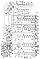
- the first control device 68 included in the main control device 42 includes two central processing units (CPUs) 160, 162, an electrically erasable programmable read-only memory (EEPROM) 164, a communicating portion 166, and A/D converting portions 168.
- the second control device 70 includes two central processing units (CPUs) 170, 172, an electrically erasable programmable read-only memory 174, a communicating portion 176 and A/D converting portions 178.
- One of the two CPUs 160, 162 of the first control device 68 serves as a first main CPU (first primary central processing unit), while the other CPU serves as a first sub-CPU (first auxiliary central processing unit).
- One of the two CPUs 170, 172 of the second control device 70 serves as a second main CPU (second primary central processing unit), while the other CPU serves as a second sub-CPU (second auxiliary central processing unit).
- Each of these CPUs 160, 162, 170, 172 is arranged to calculate the desired braking force for each of the brakes 10, 12, 14 16, 33, 34, on the basis of brake signals BS which are output signals ST and F of a stroke simulator 230 indicative of the operating stroke and depression force of the brake pedal 38, as indicated in Fig. 1.
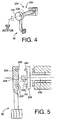
- the stroke simulator 230 includes a stroke sensor 180 and a brake pedal force sensor 182, as indicated in Fig. 3.
- the stroke sensor 180 is adapted to detect the operating stroke of the brake pedal 38, and the brake pedal force sensor 182 is adapted to detect a depression force acting on the brake pedal 38.
- the first main CPU 160 uses also vehicle condition signals VS to calculate the desired braking force.
- the vehicle condition signals VS are output signals of various sensors 183. As also indicated in Fig.
- these sensors 183 include: a vehicle acceleration sensor for detecting an acceleration value of the automotive vehicle; a yaw rate sensor for detecting a yaw rate of the of the vehicle; a steering angle sensor for detecting the operating angle of the steering wheel; an engine ECU communication switch indicative of data communication of the control device 42 with an engine control unit; a traction control off switch indicating that the traction control is off; wheel speed sensors for detecting rotating speeds of the wheels FL, FR, RL, RR; and a shift position sensor for detecting the currently selected position of an automatic transmission of the vehicle.
- the desired braking forces calculated by the other CPUs 162, 170, 172 are almost the same as calculated by the CPU 160, when the CPUs 160, 162, 170, 172 are all normal.
- the first control device including the first main CPU 160 and the first sub-CPU 162 is substantially the same as the second control device 70 including the second main CPU 170 and the second sub-CPU 172. If one of the batteries 64, 66 is defective, the desired braking forces can be calculated by the control device 68 or 70 which corresponds to the other normal battery 64, 66, so that the operations of the brakes 10, 12, 14, 16, 33, 34 can be suitably controlled.
- the desired braking forces calculated by the four CPUs 160, 162, 170, 172 are compared with each other, namely, between the desired braking forces calculated by the main CPU 160, 170 and sub-CPU 162, 172 of the same control device 68, 70, between the desired braking forces calculated by the first and second main CPUs 160, 170 of the two control devices 68, 70, and between the desired braking forces calculated by the two sub-CPUs 162, 172 of the two control devices 68, 70.
- the comparisons indicate that differences of the desired braking forces calculated by the four CPUs 160, 162, 170, 172 are all within a predetermined tolerance range, the CPUs are determined to be normal.
- the desired braking forces calculated by the main CPU and sub-CPU are checked based on the output signals of the stroke sensor 180 and the brake pedal force sensor 182.
- the main control device 42 is provided with OR gates or circuits 184, 186, 188 and AND gates or circuits 190, 192, 194, 196.
- the OR circuit 184 is connected to the first main CPU 160, first sub-CPU 162, and AND circuit 192.
- the OR gate 184 When at least one of output signals of the CPUs 160, 162 and AND circuit 192 is an abnormality signal ABN indicative of any abnormality of the CPUs 160, 162, the OR gate 184 generates a signal for de-energizing the coils of the relays 108, 112, 128, 132 and for causing a warning light (not shown) to blink, informing the vehicle operator of the presence of the abnormality. That is, the relays 108, 112, 128, 132 are turned off in any one of the following three cases: when the first main CPU 160 is abnormal; when the first sub-CPU 162 is abnormal; and when the first CPUs 160, 162 are both abnormal.
- the OR gate 186 is connected to the second main CPU 170, second sub-CPU 172 and AND circuit 190.
- the OR gate 186 generates a signal for turning off the relays 110, 114, 130, 134 and for causing the warning light to blink, in any one of the following three cases: when the second main CPU 170 is abnormal; when the second sub-CPU 172 is abnormal; and when the second CPUs 170, 172 are both abnormal.
- the relays 108, 112, 128, 132 are turned off when any abnormality of the first control device 68 takes place, and the relays 110, 114, 130, 134 are turned off when any abnormality of the second control device 70 takes place. Accordingly, the switching devices 104, 106, 124, 126 are held on when at least one of the first and second control devices 68, 70 is normal, and is turned off when both of the control devices 68, 70 become abnormal.
- the switching devices 104, 106, 124, 126 are held on even when one of the first and second control devices 68, 70 is abnormal, so that the electric energy can be supplied to the electric motors 22, 24, 30, 32, 36.
- a switching device is not provided between the motor control device 44, 46, 48, 50, 52 and the the electric motor 22, 24, 30, 32, 36, so that the electric energy can be supplied to the electric motors 22, 24, 30, 32, 36 through the switching devices 104, 106, 124, 126 and the motor control devices 44, 46, 48, 50, 52, so as to control the brakes 10, 12, 14, 16, 33, 34, even when the first or second control device 68, 70 becomes abnormal.
- Data communication is effected between the main control device 42 and each of the motor control devices 44, 46, 48, 50, 52.
- data indicative of the desired braking forces are supplied to each motor control device 44, 46, 48, 50, 52.
- data indicative of detected actual braking forces and information indicative of the operating condition (e.g., temperature data, failure data) of the electric motors 22, 24, 30, 32, 36 are supplied to the main control device 42.
- data indicative of the two desired braking forces calculated by the first and second control devices 68, 70 are supplied to each of the motor control device uses the desired braking force received from the first main CPU 160, as long as this CPU 160 is normal. As indicated in Fig.
- the motor control device 46 applies to the driver circuit 56 current signals Icu, Icv and Icw for the U, V and W phase coils of the electric motor 24, which are determined based on the received desired braking force. Amounts of electric currents Idu, Idv, Idw actually flowing through the U, V and W phase coils of the electric motor 24 are detected by current sensors 202, and are fed to the motor control device 46 through the driver circuit 56. Data indicative of these detected currents Idu, Idv, Idw, which represent the actual braking force produced by the disc brake 12, are transmitted from the motor control device 46 to the main control device 42. In the main control device 42, determinations as to whether the electric motors 22, 24, 30, 32, 36 are normal or not are effected on the basis of the actual braking forces produced.
- the data communication between the main control device 42 and the motor control devices 44, 46, 48, 50, 52 is effected through a car area network (CAN), which permits transmission and reception of a large volume of information therebetween in a short time such that different sets of information are transmitted in one direction, and such that a set of information is transmitted in the opposite directions.
- CAN car area network
- the AND circuits 194, 196 and the OR circuit 188 indicated above is provided for each of the five motor control devices 44, 46, 48, 50, 52. Namely, the AND circuits 194a-194e are provided for the respective five motor control devices, and the AND circuits 196a-196e are provided for the respective five motor control devices, while the OR circuits 188a-188e are provided for the respective five motor control devices. In Fig. 3, only one set of the AND circuits 194, 196 and OR gate 188 is shown. The AND circuits 194a, 196b and the OR circuit 188a for the motor control device 44 will be described by way of example.
- the AND circuit 194a generates a signal indicative of any abnormality of the motor control device 44 when the first main CPU 160 and the first sub-CPU 162 both determine that the motor control device 44 is abnormal.
- the AND circuit 196a generates a signal indicative of any abnormality of the motor control device 44 when the second main CPU 170 and the second sub-CPU 172 both determine that the motor control device 44 is abnormal. If at least one of these signals is received by the OR gate 188a, the OR gate 188a generates a signal for turning off the relay 150a and causing the appropriate warning light to blink, informing the vehicle operator of the presence of any abnormality of the motor control device 44.
- the main control device 42 determines that the motor control device in question is abnormal when both main CPU and sub-CPU of at least one of the first and second control devices 68, 70 determine that the motor control device is abnormal.
- the corresponding relay 150 is turned off, to turn off the corresponding motor switching device 140, 141, 142, 143, 144.
- the motor control device 44, 46, 48, 50, 52 When the motor control device 44, 46, 48, 50, 52 is determined to be abnormal, as indicated above, the electric energy is not supplied to the electric motor 22, 24, 30, 32, 36 which corresponds to the abnormal motor control device. However, the electric energies are supplied to the electric motors corresponding to the normal motor control devices, so that the corresponding brakes can be controlled as desired, by the normal motor control devices. That is, an abnormality of one of the motor control devices 44, 46, 48, 50, 52 will not prevent the supply of the electric energies to all of the electric motors.
- the motor control device 46 applies the current signals Icu, Icv, Icw to the corresponding driver circuit 54, depending upon the desired braking forces represented by the data received from the main control device 42, so that the corresponding electric currents Iu, Iv and Iw are applied from the driver circuit 56 to the respective U, V and W phase coils of the electric motor 24.
- the electric currents Iu, Iv, Iw to be applied from the driver circuit 56 to the electric motor 24 are controlled by pulse width modulation (PWM) by the motor control device 46, which is adapted to control the duty cycle, frequency, etc. of the current signals Icu, Icv, Icw, for controlling at least one transistor included in the driver portion 75b of the driver circuit 56, so as to apply the controlled electric currents Iu, Iv, Iw to the electric motor 24.
- PWM pulse width modulation
- the electric motor 24 is provided with an encoder 200, a current sensor 202, a temperature sensor 204, and a brake force sensor 206.
- the encoder 200 has a hole element for detecting a relative angular position between the stator and the rotor of the electric motor 24.
- the current sensor 202 is adapted to detect an electric current flowing through the coils of the stator, and the temperature sensor 204 is adapted to detect the temperature of the stator coils.
- the brake force sensor 206 is adapted to detect a force which is applied to the friction pads of the disc brake 12 by operation of the electric motor 24, through a rod which is advanced and retracted toward and away from the friction pads as the rotor of the electric motor 24 is rotated.
- the current signals Icu, Icv, Icw to be applied from the motor control device 46 to the driver circuit 56 are feedback-controlled on the basis of the relative angular position of the stator and the rotor detected by the encoder 200.
- the output signals of the encoder 200, current sensor 202, temperature sensor 204 and brake force sensor 206 are fed to the motor control device 46.
- the actual braking force produced by the disc brake 12 is estimated on the basis of the current detected by the current sensor 202, and data indicative of the estimated actual braking force are transmitted to the main control device 42.
- the electric currents to be applied to the electric motor 24 are feedback-controlled on the basis of the actual braking force detected by the brake force sensor 206.
- the temperature detected by the temperature sensor 204 is used for checking the electric motor 24 for abnormality. If the detected temperature or the rate of increase of the detected temperature is higher than a predetermined threshold, the electric motor 24 is determined to be abnormal. In this case, the relay 152b is turned off, and the motor switching device 141 is turned off, so that the electric motor 24 is disconnected from both of the batteries 64, 66, and is prevented from being kept operated.
- the motor switching devices 140-144 are selectively turned off independently of each other when the corresponding electric motors 22, 24, 30, 32, 36 become abnormal, so that only the abnormal electric motor or motors is/are turned off, while the normal electric motor or motors is/are held in operation or operable, whereby the brake or brakes corresponding to the normal electric motor or motors can be activated. That is, an abnormality of any electric motor will not prevent normal operations of the other normal electric motors for activating the corresponding brakes.
- the electric motors 22, 24 used for the front disc brakes 10, 12 are brushless DC motors
- the electric motors 30, 32 used for the rear drum brakes 14, 16 and the electric motor 36 used for the parking brakes 33, 34 are DC motors.
- the stator of the brushless DC motor has a U-phase coil, a V-phase coil and a W-phase coil which are energized by the electric currents Iu, Iv, Iw, the duty cycles of which are controlled depending upon the output signal of the encoder 200, for example.
- the brushless DC motor has a comparatively higher degree of durability owing to the absence of brushes.
- the electric motors 22, 24 for the front disc brakes 10, 12 have a 36V rating, while the electric motors 30, 32 for the rear drum brakes 14, 16 have a 12V rating. Accordingly, the front disc brakes 10, 12 are capable of producing larger braking forces than the rear drum brakes 14, 16.
- the motor control devices 44, 46, 48, 50, 52 are attached to a suitable member of the vehicle body such that each motor control device is disposed near the corresponding wheel.
- data communication is effected between the main control device 42 and each motor control device 44, 46, 48, 50, 52, and between the motor control device and the corresponding driver circuit 54, 56, 58, 60, 62.
- this arrangement results in an increase in the cost of manufacture, due to requirements for increased data storage capacity and an increased number of input and output ports. Further, the arrangement results in increased distances between the driver circuits and the electric motors. For these reasons, therefore, the arrangement in question is not desirable.
- the driver circuits and the motor control devices are spaced a relatively long distance from the main control device 42, that is, where the distances therebetween are comparatively long, a relatively long time is required for the data communication therebetween. While the driver circuits must be disposed on an unsprung member of the vehicle, the motor control devices if also disposed on an unsprung member are subject to vibrations having a comparatively large amplitude. In this respect, it is not desirable to dispose the motor control devices on the unsprung member.
- the motor control devices in the present braking system are disposed on a sprung member of the vehicle and positioned near the driver circuits.
- this arrangement results in relatively long distances between the main control device 42 and the motor control devices, these devices will not suffer from undesirable noises, since they are disposed on the sprung member.
- the data communication between the main control device and the motor control devices through the CAN (car area network) permits high-speed transmission of a large volume of information in a relatively short time even where the communication distances are relatively long.
- the motor control devices disposed on the spring member are protected from vibrations of a large amplitude.
- the driver circuits may also be disposed on a sprung member.
- the stroke simulator 230 is attached to the brake pedal 38, which is attached at a proximal portion 232 thereof to a mount 234 such that the brake pedal 38 is pivotable about an axis.
- the mount 234 includes a torsion bar 236 and a connector 238.
- the torsion bar 236 is attached at its one end to a suitable member of the vehicle body, and is associated at the other end to the brake pedal 38 through the connecting portion 238 such that the torsion bar 236 is not rotatable relative to the brake pedal 38, except during an initial period of an operation (pivotal movement) of the brake pedal 38.
- the torsion bar 236 and the connector 238 permit an increase in the operating stroke of the brake pedal 38 during an initial period of operation of the brake pedal 38, and the torsion bar 236 is twisted as the operating force acting on the brake pedal 38 is increased beyond a given value, permitting a further increase in the operating stroke of the brake pedal 38.
- the connecting portion 238 fixed to the above-indicated other end of the torsion bar 236 takes the form of a circular disc which has a central boss 240 located at an axis of rotation thereof, and two pins 241, 242 located at respective radially intermediate positions thereof.
- the proximal portion 232 of the brake pedal 38 has a central connecting hole 244 corresponding to the central boss 240, and two elongate arcuate grooves 245, 246 formed in one of its opposite surfaces which faces the connecting portion 238.
- the central boss 240 engages the central connecting hole 244 while the two pins 241, 242 engages the respective arcuate grooves 245, 246.
- the arcuate groove 246 has a smaller length than the arcuate groove 245, and an elastic member 248 is disposed in the arcuate groove 245.
- each of the two pins 241, 242 is located at a downstream one of the opposite ends of the corresponding arcuate groove 245, 246, as seen in the rotating direction of the proximal portion 232 of the brake pedal 38. Then the brake pedal 38 is depressed, the proximal portion 232 is rotated relative to the pins 241, 242 such that the pins 241, 242 are moved within the respective grooves 245, 246 toward the upstream end of each groove.
- the elastic member 248 is elastically deformed permitting an increase in the operating stroke of the brake pedal 38, but substantially no twisting of the torsion bar 346 takes place during this initial period.
- the pins 240, 241 have been brought into abutting contact with the upstream ends of the arcuate grooves 245, 246, the torsion bar 236 is twisted as the brake pedal 38 is further depressed.
- the operating stroke of the brake pedal 38 increases as the operating force increases.
- the stroke simulator 230 gives different operating characteristics of the brake pedal 38 during the initial and subsequent periods of operation or pivotal rotation of the brake pedal 38, thus simulating the operating stroke of the brake pedal 38 which would be obtained if the operating force were directly used to activate the brakes 10, 12, 14, 16, 33, 34.
- the stroke sensor 180 and brake pedal force sensor 182 which have been described are provided on the stroke simulator 230.
- the operating stroke of the brake pedal 38 is detected by the stroke sensor 180, on the basis of an angular position of the torsion bar 236 relative to the vehicle body member to which the torsion bar is attached.
- the operating force acting on the brake pedal 38 is detected by the brake pedal force sensor 182, on the basis of an amount of surface strain of the torsion bar 236.
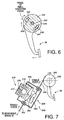
- the automotive vehicle including the present electrically operated braking system further includes a manually operated emergency brake device 250, which includes: the brake pedal 38; the parking brakes 33, 34 provided on the rear left and right wheels RL, RR; a first wire 252 for operating the parking brakes 33, 34; a force transmitter 254 serving as a switching mechanism; and a second wire 256 for connected to the brake pedal 38 such that the second wire 256 is pulled when the brake pedal 38 is operated.
- the first wire 252 is used for transmitting a force for forcing the friction members in the form of brake linings of the parking brakes 33, 35 onto the brake drums which are also used for the rear drum brakes 14, 16.
- the first wire 252 is connected at its one end to the force transmitter 254, as shown in Fig. 7, and at its other end to a linkage 257, as shown in Fig. 1. To the linkage 257, there are connected two third wires 258 which are pulled for operating the parking brakes 33, 34 when the first wire 252 is pulled by the brake pedal 38.
- the force transmitter 254 which selectively transmits the operating force of the brake pedal 38 to the first wire 252, includes: first engaging portion 260 to which the first wire 252 is connected; a second engaging portion 262 to which the second wire 256 is connected; a first spring 264 for biasing the first engaging portion 260 in a direction of disengagement of the first engaging portion 260 from the second engaging portion 262; and an actuator 270 for selective engagement and disengagement of the first and second engaging portions 260, 262.
- the actuator 270 which serves as a switching control device, includes a plunger 274, a solenoid coil 276, and a spring 278.
- the solenoid coil 276 is normally held in an energized state for holding the plunger 274 in its retracted position for holding the first and second engaging portions 260, 262 in their disengaged state. In this state, the first and second wires 252, 256 are not connected to each other.
- the plunger 274 When the solenoid coil 276 is de-energized, the plunger 274 is moved to its advanced position by the biasing force of the spring 278, against the biasing force of the first spring 264, whereby the first engaging portion 260 is moved by the plunger 274, for engagement with the second engaging portion 262, so that the first and second wires 252, 256 are connected to each other by the force transmitter 254.
- the solenoid coil 276 is de-energized when the supply of an electric current to the main control device 42 and motor control devices 44, 46, 48, 50, 52 is interrupted in the event of some electrical abnormality of the electric system.
- the pull force corresponding to the operating force of the brake pedal 38 is applied to the brake linings of the parking brakes 33, 34 through the second wire 256, first wire 252 and third wires 258, so that the parking brakes 33, 34 are activated as mechanically operated emergency brakes.
- the parking brakes 33, 34 are activated when a fourth wire 280 is pulled by operation of the electric motor 36 upon operation of the parking brake switch 35.
- the linkage 257 to which the first and fourth wires 252, 280 are connected is constructed such that the third wire 258 is pulled when one of the first and fourth wires 252, 280 is pulled by operation of the brake pedal 38 or electric motor 36.
- FIGs. 8-10 there will be described an electrically controlled braking system constructed according to a second embodiment of this invention.
- the same reference numerals and signs as used in the first embodiment will be used in the second embodiment, to identify the corresponding elements, and redundant description of these elements will not be provided.
- the present braking system uses a main control device 300 which includes three CPUs 302, 304, 306, three EEPROMs 308 corresponding to the CPUs 302, 304, 306, and three A/D converters 309 corresponding to the CPUs 303, 304, 306.
- three batteries 312, 314, 316 are connected to the respective three CPUs 302, 304, 307.
- An alternator 317 is connected to the three batteries 312, 314, 316, for storing electric energies therein.
- Each of the batteries 312 and 314 is adapted to store the electric energies of 12V and 36V, while the battery 316 is adapted to store the electric energy of 12V.
- Each of the batteries 312, 314 has two terminals used to supply the electric energies of 12V and 36, respectively.
- the batteries 312, 314, 316 cooperate to serve as an electric power source device.
- this battery 312 is connected to a first group of control devices consisting of the first CPU 302 and the motor control device 44 and driver circuit 54 for the front left wheel FL, and to the electric motor 22 for the front left wheel FL.
- this battery 314 is connected to a second group of control devices consisting of the second CPU 304 and the electric motor 46 and driver circuit 56 for the front right wheel FR, and to the electric motor 24 for the front right wheel FR.
- this battery 316 is connected to a third group of control devices consisting of the third CPU 304, the motor control devices 48, 50 and driver circuits 58, 60 for the rear left and right wheels RL, RR and the motor control device 52 and driver circuit 62 for the parking brakes 33, 34, and to a group of electric motors consisting of the electric motors 30, 32 for the rear left and right wheels FL, FR and the electric motor 36 for the parking brake 36.
- the electric energies of the batteries 312, 314, 316 are supplied to the respective first, second and third CPUs 302, 304, 406, independently of each other, so that even in the event of abnormality of one or two of the the batteries 312, 314, 316, the CPU or CPUs corresponding to the normal one or ones of the three batteries can be normally operated, permitting the normal operation of the brakes 10, 12, 14, 16, 33, 34.
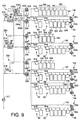
- a power source switching device 330 (Fig. 9) is turned on when at least one of switches 332a, 332b of an ignition switch and a brake switch 334 is turned on, and is turned off when all of the switches 332a, 332b and brake switch 334 are turned off.
- a coil 336 is energized, and a switching portion 338 is turned on.
- the brake switch 334 includes two switches 334a, 334b connected in series with each other, and is turned off when one of these two switches is turned off. While the two switches 332a, 332b are shown in Fig. 9 such that these two switches are connected in series with each other, there is actually a single ignition switch which is operated by the vehicle operator.
- Fig. 9 shows the two switches 332a, 332b whose operating states are changed in response to an operation of the ignition switch.
- the ignition switch 332a is connected to the battery 312, while the ignition switch 332b is connected to the battery 314.
- the power source switching device 330 can be turned on when the ignition switch is turned on.
- the power source switching device 330 can be turned on when the brake switch 334 is turned on with the brake pedal 38 being operated.
- each of the three CPUs 302, 304, 306 calculates the desired braking force on the basis of the operating stroke of the brake pedal 38 detected by the stroke sensor 180, and applies the appropriate current signals Icu, Icv, Icw to each motor control device 44, 46, 48, 50, 52, which determines the desired braking force value by decision of majority on the basis of the three desired braking force values received from the three CPUs, and applies the appropriate amounts of electric current Iu, Iv, Iw to the corresponding electric motor 22, 24, 30, 32 through the corresponding driver circuit 54, 56, 58, 60.
- the signals indicative of the detected actual current values Idu, Idv, Idw are fed from each driver circuit to the main control device 300 through the motor control device, so that the CPUs 302, 304, 306, 308 can check if the corresponding motor control devices 54, 56, 58, 60 are normal.
- signals MTR. ECU ABN indicating the abnormality are applied to two of three AND circuits 340, 342, 444 provided for the corresponding one of the five motor control devices 44, 46, 48, 50, 52.
- the AND circuits 340a, 342a, 344a are provided for the motor control device 44, and the AND circuits 340b, 342b, 344b are provided for the motor control device 46. Similarly, the three AND circuits 340, 342, 344 are provided for each of the other motor control devices 48, 50, 52. In Fig. 10, only one set of AND circuits 340, 342, 344 is shown, in the interest of brevity.
- the first CPU 302 is connected to the two AND circuits 340, 342, and the second CPU 304 is connected to the two AND circuits 340, 344, while the third CPU 306 is connected to the two AND circuits 342, 344.
- the three AND circuits 340, 342, 344 are connected to an OR circuit 346.
- the OR circuit 346 receives an abnormality signal from at least one of the three AND circuits 340, 342, 344, the OR circuit 346 generates a signal for de-energizing the coil of the relay 150 and for causing the warning light to be activated to indicate that the corresponding motor control device is abnormal.
- the relay 150 being turned off, the corresponding motor switching device is turned off, as in the first embodiment. Namely, when at least two of the three CPUs determine that a certain one of the motor control devices 44, 46, 48, 50, 52 is abnormal, the abnormality signal is generated from the corresponding OR circuit 346.
- abnormality signals are applied from the CPU 302 to the AND circuits 340a, 342a, and from the CPU 304 to the AND circuits 340a, 344a.
- the abnormality signal is fed from the AND circuit 340a to the OR circuit 346a, and the OR circuit 346a generates the signal for turning off the relay 150a.
- the coil 336 in the electric circuit corresponding to the CPU in question is de-energized, to turn off the switching portion 338.
- the determination for abnormality of the calculated desired braking force values is also based on the output signal of the stroke sensor 180.
- LAN local area network
- CAN car area network
- the determination on abnormality of the braking system can be easily made according to decision by majority. Since each of the three CPUs is powered by the exclusive battery, the brakes 10, 12, 14, 16, 33, 34 can be activated unless the three batteries are abnormal.
- the electric motors 22, 24 for the front wheels are brushless DC motors while the electric motors 30, 32, 36 for the rear wheels are DC motors, all of these motors are DC motors or brushless DC motors. Further, other types of motors such as 3-phase AC motors and ultrasonic motors may be used, and all of the motors for the front and rear wheels may be 36V motors or 12V motors. While the disc brakes 10, 12 are used for the front wheels and the drum brakes 14, 16 are used for the rear wheels, the brakes for all of the four wheels may be disc brakes or drum brakes. Further, the illustrated embodiments may be suitably modified in connection with the number of the batteries and/or switching devices used.
- the brake switch 90 of the power source switching devices 78, 79 includes the two switches 96, 98 connected in series with each other, the brake switch 90 may include three or more switches.
- the switching devices are not limited to those including relays, but may use transistors, and may or may not include contactors. It will be understood that the present invention may be embodied with various other modifications such as those described in the SUMMARY OF THE INVENTION, which may occur to those skilled in the art. For instance, the logic circuit arrangements including the AND and OR circuits may be replaced by software programs.
- An electrically controlled braking system including an electrically controlled brake (10, 12, 14, 16, 33, 34) for braking a vehicle wheel (FL, FR, RL, RR), an electric power source device (64, 66; 312, 314, 316), a brake control apparatus (18) for controlling an electric energy to be supplied from the electric power source device to the brake, for thereby controlling an operation of the brake, when a brake operating member (38) is operated, and a switching device (78, 79; 330) disposed between the electric power source device (64, 66; 312, 314, 316) and the brake control apparatus (18), and wherein the switching device is turned on for connecting the electric power source device to the brake control apparatus, in response to an operation of the brake operating member.
Landscapes
- Engineering & Computer Science (AREA)
- Transportation (AREA)
- Mechanical Engineering (AREA)
- Regulating Braking Force (AREA)
- Valves And Accessory Devices For Braking Systems (AREA)
- Braking Systems And Boosters (AREA)
Priority Applications (1)
| Application Number | Priority Date | Filing Date | Title |
|---|---|---|---|
| EP07102161A EP1832482B1 (de) | 1999-02-03 | 2000-02-02 | Bremssystem mit Schaltvorrichtung zur Energieversorgung einer elektrisch gesteuerten Bremse durch ein Bremssteuergerät bei Betätigung eines Bremsbetätigungselements |
Applications Claiming Priority (2)
| Application Number | Priority Date | Filing Date | Title |
|---|---|---|---|
| JP11026158A JP2000225935A (ja) | 1999-02-03 | 1999-02-03 | 電気制御ブレーキシステム |
| JP2615899 | 1999-02-03 |
Related Child Applications (1)
| Application Number | Title | Priority Date | Filing Date |
|---|---|---|---|
| EP07102161A Division EP1832482B1 (de) | 1999-02-03 | 2000-02-02 | Bremssystem mit Schaltvorrichtung zur Energieversorgung einer elektrisch gesteuerten Bremse durch ein Bremssteuergerät bei Betätigung eines Bremsbetätigungselements |
Publications (2)
| Publication Number | Publication Date |
|---|---|
| EP1026060A2 true EP1026060A2 (de) | 2000-08-09 |
| EP1026060A3 EP1026060A3 (de) | 2003-07-23 |
Family
ID=12185752
Family Applications (2)
| Application Number | Title | Priority Date | Filing Date |
|---|---|---|---|
| EP07102161A Expired - Lifetime EP1832482B1 (de) | 1999-02-03 | 2000-02-02 | Bremssystem mit Schaltvorrichtung zur Energieversorgung einer elektrisch gesteuerten Bremse durch ein Bremssteuergerät bei Betätigung eines Bremsbetätigungselements |
| EP00102059A Withdrawn EP1026060A3 (de) | 1999-02-03 | 2000-02-02 | Bremssystem |
Family Applications Before (1)
| Application Number | Title | Priority Date | Filing Date |
|---|---|---|---|
| EP07102161A Expired - Lifetime EP1832482B1 (de) | 1999-02-03 | 2000-02-02 | Bremssystem mit Schaltvorrichtung zur Energieversorgung einer elektrisch gesteuerten Bremse durch ein Bremssteuergerät bei Betätigung eines Bremsbetätigungselements |
Country Status (4)
| Country | Link |
|---|---|
| US (1) | US6749269B1 (de) |
| EP (2) | EP1832482B1 (de) |
| JP (1) | JP2000225935A (de) |
| DE (1) | DE60044654D1 (de) |
Cited By (17)
| Publication number | Priority date | Publication date | Assignee | Title |
|---|---|---|---|---|
| WO2003100282A1 (de) * | 2002-05-28 | 2003-12-04 | Estop Gmbh | Fehler-sicherheitskonzept für eine elektromechanische bremse |
| FR2902397A1 (fr) * | 2006-06-16 | 2007-12-21 | Peugeot Citroen Automobiles Sa | Systeme de freinage electrique pour un vehicule |
| FR2902707A1 (fr) * | 2006-06-26 | 2007-12-28 | Conception & Dev Michelin Sa | Architecture materielle rebondante pour etage d'alimentation basse tension d'un systeme de freinage d'un vehicule dont toutes les roues sont reliees chacune a au moins une machine electrique rotative |
| DE102007021286A1 (de) * | 2007-05-07 | 2008-11-13 | Continental Automotive Gmbh | Elektromechanisches Bremssystem mit einer ausfallsicheren Energieversorgung und Verfahren zur ausfallsicheren Energieversorgung in einem elektromechanischen Bremssystem für Fahrzeuge |
| WO2009004022A2 (de) * | 2007-07-03 | 2009-01-08 | Continental Automotive Gmbh | Verfahren und anordnung zum fahrbahnspezifischen feststellbremsen eines fahrzeuges |
| EP2035250A1 (de) * | 2006-06-26 | 2009-03-18 | Societe de Technologie Michelin | Redundante hardware-architektur für die steuersignalstufe des bremssystems eines fahrzeugs, bei dem alle räder mit mindestens einer elektrischen rotationsmaschine verbunden sind |
| WO2009037352A1 (fr) * | 2007-09-20 | 2009-03-26 | Societe De Technologie Michelin | Architecture matérielle redondante pour l'étage de signaux de commande d'un système de freinage d'un véhicule dont toutes les roues sont reliées chacune à au moins une machine électrique rotative. |
| WO2009065754A2 (de) * | 2007-11-23 | 2009-05-28 | Continental Automotive Gmbh | Verfahren zur ansteuerung von zumindest einer elektromechanischen parkbremseneinheit eines elektromechanischen parkbremssystems |
| US7748793B2 (en) | 2002-05-28 | 2010-07-06 | Estop Gmbh | Fail-safe concept for an electromechanical brake |
| CN102529921A (zh) * | 2010-12-14 | 2012-07-04 | Nxp股份有限公司 | 分布式电制动电路及系统 |
| US8449049B2 (en) | 2006-06-26 | 2013-05-28 | Michelin Recherche Et Technique S.A. | Redundant hardware architecture for the power stage of the braking system of a vehicle in which each of the wheels are connected to at least one rotary electrical machine |
| WO2013083301A1 (de) * | 2011-12-07 | 2013-06-13 | Continental Teves Ag & Co. Ohg | Verfahren sowie elektronische einrichtung zur verbesserung der verfügbarkeit eines elektromechanischen aktuators |
| US8752908B2 (en) | 2006-06-27 | 2014-06-17 | Continental Teves Ag & Co. Ohg | Parking brake system for motor vehicles |
| WO2017215808A1 (de) * | 2016-06-13 | 2017-12-21 | Robert Bosch Gmbh | Verfahren zum betrieb eines fahrzeugregelsystems |
| EP3199416A4 (de) * | 2014-09-25 | 2018-05-30 | NTN Corporation | Elektrisches bremssystem |
| EP3318459A4 (de) * | 2015-07-02 | 2019-05-01 | Mitsubishi Jidosha Kogyo Kabushiki Kaisha | Elektromechanische bremsvorrichtung |
| WO2020099329A1 (de) * | 2018-11-12 | 2020-05-22 | Marcel Alper Gmbh | Fahrzeugkomponente |
Families Citing this family (38)
| Publication number | Priority date | Publication date | Assignee | Title |
|---|---|---|---|---|
| DE10118262A1 (de) * | 2001-04-12 | 2002-10-17 | Bosch Gmbh Robert | Elektrisches Bremssystem |
| JP2004314687A (ja) * | 2003-04-11 | 2004-11-11 | Asmo Co Ltd | 電動駐車ブレーキシステム |
| JP2005096680A (ja) * | 2003-09-26 | 2005-04-14 | Tokico Ltd | 電動ブレーキ装置 |
| US7359786B2 (en) * | 2003-09-29 | 2008-04-15 | Haldex Brake Products Ab | Control and power supply network for vehicle braking system |
| JP4848027B2 (ja) * | 2004-01-30 | 2011-12-28 | 日立オートモティブシステムズ株式会社 | 車両制御装置 |
| EP1750985A1 (de) * | 2004-05-13 | 2007-02-14 | Haldex Brake Products AB | Modulares bremssystem |
| US6953904B1 (en) | 2004-09-30 | 2005-10-11 | Emerson Electric Co. | Pedal actuated switch assembly |
| FR2878215B1 (fr) * | 2004-11-25 | 2007-01-05 | Renault Sas | Dispositif de freinage electrique pour vehicule |
| US7401867B2 (en) * | 2005-03-23 | 2008-07-22 | Delphi Technologies, Inc. | Dynamic identification of brake-by-wire components |
| JP2007230318A (ja) * | 2006-02-28 | 2007-09-13 | Hitachi Ltd | 電動ブレーキシステム |
| US9108602B2 (en) * | 2006-12-05 | 2015-08-18 | The Boeing Company | Parking brake control for an aircraft having an electric brake system |
| US8215436B2 (en) * | 2007-01-03 | 2012-07-10 | Degrave Ken | Hybrid trailer system |
| JP4333751B2 (ja) * | 2007-02-15 | 2009-09-16 | 株式会社デンソー | ブラシレスモータの駆動装置 |
| US8386148B2 (en) * | 2007-12-31 | 2013-02-26 | The Invention Science Fund I, Llc | Traffic-sensitive engine control |
| US8335635B2 (en) * | 2007-12-31 | 2012-12-18 | The Invention Science Fund I, Llc | System and method for operating a vehicle |
| US7957892B2 (en) * | 2007-12-31 | 2011-06-07 | The Invention Science Fund I, Llc | Condition-sensitive exhaust control |
| US8335636B2 (en) * | 2007-12-31 | 2012-12-18 | The Invention Science Fund I, Llc | System and method for remotely modifying vehicle operations |
| JP4701254B2 (ja) * | 2008-02-04 | 2011-06-15 | 日立オートモティブシステムズ株式会社 | ブレーキ装置 |
| KR20110033624A (ko) * | 2009-09-25 | 2011-03-31 | 주식회사 만도 | 전자식 주차 브레이크 시스템 및 그 제어 방법 |
| JP5400716B2 (ja) * | 2010-06-30 | 2014-01-29 | 日立建機株式会社 | 電動車両の駆動力制御装置 |
| KR101159506B1 (ko) | 2010-09-13 | 2012-06-26 | 주식회사 만도 | 전동식 제동장치의 제어방법 |
| KR101265951B1 (ko) * | 2011-06-28 | 2013-05-21 | 주식회사 만도 | 전자식 주차 브레이크 시스템의 제어 방법 |
| DE102013004936A1 (de) * | 2013-03-22 | 2014-09-25 | Dynapac Gmbh | Verfahren zum Bremsen eines selbstfahrenden Straßenfertigers oder Beschickers sowie Bremsanlage für einen selbstfahrenden Straßenfertiger oder Beschicker |
| US9469315B2 (en) * | 2013-05-22 | 2016-10-18 | Wabtec Holding Corp. | Thermally optimized railway vehicle brake system |
| JP6221517B2 (ja) * | 2013-08-29 | 2017-11-01 | 株式会社アドヴィックス | 車両の電動制動装置 |
| KR102158482B1 (ko) * | 2014-08-18 | 2020-09-23 | 현대모비스 주식회사 | 긴급제동 발생시 3상 모터 제어를 위한 확장된 전류 검출 방법 |
| JP6565388B2 (ja) | 2015-07-02 | 2019-08-28 | 三菱自動車工業株式会社 | 電動ブレーキ装置 |
| CN108025687B (zh) * | 2015-09-29 | 2021-12-21 | 日立安斯泰莫株式会社 | 监视系统及车辆用控制装置 |
| US10501063B2 (en) * | 2016-08-29 | 2019-12-10 | GM Global Technology Operations LLC | Brake-by-wire system |
| JP6855832B2 (ja) * | 2017-02-21 | 2021-04-07 | トヨタ自動車株式会社 | 車両の駆動システム |
| WO2018181808A1 (ja) | 2017-03-31 | 2018-10-04 | 日信工業株式会社 | 車両用ブレーキシステム |
| CN110546053B (zh) * | 2017-03-31 | 2022-06-17 | 日立安斯泰莫株式会社 | 车辆用制动系统 |
| US20180290640A1 (en) * | 2017-04-06 | 2018-10-11 | Ford Global Technologies, Llc | Methods and apparatus to control vehicle braking systems |
| CN110799394B (zh) * | 2017-06-28 | 2022-02-01 | 日立安斯泰莫株式会社 | 车辆用制动系统 |
| KR102539406B1 (ko) * | 2019-04-22 | 2023-06-01 | 히다치 아스테모 가부시키가이샤 | 제어 장치 |
| US20210031782A1 (en) * | 2019-08-01 | 2021-02-04 | 7980302 Canada Inc. | Using ISA System to Immobilize Truck for Security, Regulatory Compliance, or Maintenance |
| US11702083B2 (en) | 2020-06-11 | 2023-07-18 | 7980302 Canada Inc. | Using ISA system to implement a speed policy identified based on profile of a driving instance |
| KR20220102001A (ko) * | 2021-01-12 | 2022-07-19 | 현대모비스 주식회사 | 전동식 브레이크의 제어장치 및 방법 |
Citations (2)
| Publication number | Priority date | Publication date | Assignee | Title |
|---|---|---|---|---|
| JPH01126158A (ja) | 1987-11-06 | 1989-05-18 | Mitsubishi Electric Corp | 超電導回転電機の回転子 |
| JPH05158742A (ja) | 1991-12-09 | 1993-06-25 | Sumitomo Electric Ind Ltd | 複数のマイクロコンピュータの暴走監視回路 |
Family Cites Families (50)
| Publication number | Priority date | Publication date | Assignee | Title |
|---|---|---|---|---|
| US3498426A (en) * | 1966-10-21 | 1970-03-03 | Akio Nakano | Hydraulic brake operating system for a motor vehicle |
| US3684049A (en) * | 1969-02-19 | 1972-08-15 | Seiji Kimura | Vehicle foot brake locking mechanism; foot brake locking mechanism release means; and parking brake locking mechanism release means |
| US3645352A (en) * | 1970-06-22 | 1972-02-29 | Ford Motor Co | Anticreep brake system for a wheeled vehicle |
| US3651457A (en) * | 1970-08-14 | 1972-03-21 | Reuben Sprouse | Warning system for vehicles with air-type parking brakes |
| US3792742A (en) * | 1972-02-08 | 1974-02-19 | C Mager | Electric motor operated vehicle |
| JPS5153333A (en) * | 1974-08-02 | 1976-05-11 | Honda Motor Co Ltd | Jidohensokukitsukisharyono gensokujotaikenshutsusochi |
| FR2281250A1 (fr) * | 1974-08-07 | 1976-03-05 | Messier Hispano Sa | Procede et systeme de double commande de freinage |
| US4561527A (en) * | 1983-01-31 | 1985-12-31 | Mazda Motor Corporation | Electric parking brake system for a vehicle |
| DE3410006A1 (de) * | 1984-03-19 | 1985-09-19 | Alfred Teves Gmbh, 6000 Frankfurt | Verfahren zur steuerung einer bremsanlage fuer kraftfahrzeuge und vorrichtung zur durchfuehrung des verfahrens |
| US4721344A (en) * | 1984-10-22 | 1988-01-26 | Kelsey-Hayes Company | Electric brake controller |
| JPS61244658A (ja) * | 1985-04-23 | 1986-10-30 | Nippon Air Brake Co Ltd | 電気車用空気ブレ−キ制御装置 |
| JPH0678057B2 (ja) * | 1985-04-25 | 1994-10-05 | 富士重工業株式会社 | ブレ−キ装置 |
| US4655634A (en) * | 1985-09-23 | 1987-04-07 | Dresser Industries, Inc. | Road planer control and safety system |
| JP2590825B2 (ja) * | 1986-07-12 | 1997-03-12 | トヨタ自動車株式会社 | マニユアル・電気二系統ブレーキ装置 |
| DE3636263A1 (de) * | 1986-10-24 | 1988-04-28 | Teves Gmbh Alfred | Elektrische schaltvorrichtung |
| JP2841887B2 (ja) * | 1991-01-23 | 1998-12-24 | トヨタ自動車株式会社 | ブレーキ制御方法 |
| IT1253747B (it) * | 1991-08-02 | 1995-08-23 | Brembo Spa | Impianto frenante per vetture a trazione elettrica |
| DE4229041A1 (de) * | 1991-09-06 | 1993-03-11 | Akebono Brake Ind | Fahrzeug-bremssteuersystem |
| DE4227083C2 (de) * | 1992-08-17 | 2002-06-27 | Knorr Bremse Systeme | Elektronisches Bremssystem, insbesondere für Straßenfahrzeuge |
| JP3235218B2 (ja) * | 1992-10-22 | 2001-12-04 | 住友電気工業株式会社 | 車両用の副給電回路 |
| JPH0637016U (ja) * | 1992-10-23 | 1994-05-17 | 株式会社東海理化電機製作所 | 乗員保護装置用センサ |
| US5418437A (en) * | 1992-11-16 | 1995-05-23 | Hydro-Quebec | Motor vehicle drive system for a motor vehicle having an electric motor system, and a method of operating said drive system |
| JPH06199221A (ja) * | 1992-12-28 | 1994-07-19 | Daihatsu Motor Co Ltd | アンチスキッド装置の故障検出方法 |
| JPH06276608A (ja) * | 1993-03-19 | 1994-09-30 | Fuji Electric Co Ltd | 電気自動車の電気システム |
| US5532674A (en) * | 1993-05-28 | 1996-07-02 | Michaud; Paul J. | Idle brake light system |
| FR2709457B1 (fr) | 1993-09-02 | 1995-12-08 | Peugeot | Installation de freinage pour véhicules automobile du type à système anti-blocage des roues. |
| US5519256A (en) * | 1994-01-31 | 1996-05-21 | Goodridge; Eugene W. | Motor vehicle lights, auxiliary brake and cruise controls |
| US5533795A (en) * | 1994-08-09 | 1996-07-09 | Brooks; Louie J. | Brake safety system for vehicles with seat and door control |
| US5620236A (en) * | 1994-09-27 | 1997-04-15 | Hayes Wheels International, Inc. | Electronic trailer brake controller |
| US5862048A (en) * | 1994-10-05 | 1999-01-19 | New York Air Brake Corporation | Microprocessor based electro-pneumatic locomotive brake control and train monitoring system |
| DE19521175C1 (de) * | 1995-06-10 | 1996-07-11 | Continental Ag | Elektrisch regelbares Bremssystem |
| DE19548392C2 (de) | 1995-12-22 | 2001-05-17 | Siemens Ag | Bremsanlage für ein Kraftfahrzeug |
| DE19548560C5 (de) * | 1995-12-23 | 2010-11-11 | Robert Bosch Gmbh | Verfahren und Vorrichtung zur Steuerung der Bremsanlage eines Fahrzeugs |
| DE19601983C1 (de) * | 1996-01-20 | 1997-07-24 | Continental Ag | Bremsanlage für ein Kraftfahrzeug |
| DE19604946C2 (de) * | 1996-02-10 | 1998-12-17 | Continental Ag | Verfahren zur kontrollierten Inbetriebnahme eines Fahrzeugs |
| DE19617285C1 (de) * | 1996-04-30 | 1997-08-21 | Continental Ag | Verfahren zum Betreiben einer elektrischen Bremsanlage eines Kraftfahrzeuges |
| DE19620491A1 (de) * | 1996-05-21 | 1997-11-27 | Ulrich Heller | Sicherheitsbremse gegen unbeabsichtigtes Rollen eines Fahrzeugs |
| JP3032657U (ja) * | 1996-06-20 | 1996-12-24 | 日清紡績株式会社 | アンチロックブレーキ制御装置用モータリレー回路 |
| JPH1061538A (ja) * | 1996-08-15 | 1998-03-03 | Suzuki Motor Corp | スタータ装置のスタータモータ保護装置 |
| DE19634567B4 (de) * | 1996-08-27 | 2007-11-29 | Robert Bosch Gmbh | Elektrisches Bremssystem |
| JP2000501047A (ja) * | 1996-09-19 | 2000-02-02 | ローベルト ボツシユ ゲゼルシヤフト ミツト ベシユレンクテル ハフツング | 自動車の駆動系を制御する装置並びに方法 |
| DE19638759C2 (de) * | 1996-09-21 | 2000-11-16 | Continental Ag | Elektrische Anlage für ein Kraftfahrzeug |
| JP3837195B2 (ja) * | 1996-12-26 | 2006-10-25 | 曙ブレーキ工業株式会社 | パッドクリアランス調整機構を備えた電動ブレーキとそのパッドクリアランス調整法 |
| JPH10217936A (ja) | 1997-02-10 | 1998-08-18 | Tokico Ltd | 車両用ブレーキ制御装置 |
| DE19743305C2 (de) * | 1997-09-30 | 2001-03-15 | Siemens Ag | Anordnung zur Sicherstellung des Lösens einer selbsthemmenden Bremse während eines Bremsvorgangs eines Fahrzeugs |
| EP1032517B1 (de) * | 1997-11-22 | 2005-01-26 | Continental Teves AG & Co. oHG | Elektromechanisches bremssystem |
| DE19826131A1 (de) | 1998-06-12 | 1999-12-16 | Bosch Gmbh Robert | Elektrisches Bremssystem für ein Kraftfahrzeug |
| DE19828331C1 (de) * | 1998-06-25 | 2000-03-02 | Continental Ag | Verfahren zum Betreiben einer elektromechanischen Bremsanlage |
| JP4723706B2 (ja) * | 1999-09-02 | 2011-07-13 | トヨタ自動車株式会社 | 車両用電気制御システム |
| JPWO2005110814A1 (ja) * | 2004-05-13 | 2008-03-21 | 株式会社日立製作所 | 電動ブレーキシステム |
-
1999
- 1999-02-03 JP JP11026158A patent/JP2000225935A/ja active Pending
-
2000
- 2000-01-31 US US09/495,447 patent/US6749269B1/en not_active Expired - Lifetime
- 2000-02-02 EP EP07102161A patent/EP1832482B1/de not_active Expired - Lifetime
- 2000-02-02 DE DE60044654T patent/DE60044654D1/de not_active Expired - Lifetime
- 2000-02-02 EP EP00102059A patent/EP1026060A3/de not_active Withdrawn
Patent Citations (2)
| Publication number | Priority date | Publication date | Assignee | Title |
|---|---|---|---|---|
| JPH01126158A (ja) | 1987-11-06 | 1989-05-18 | Mitsubishi Electric Corp | 超電導回転電機の回転子 |
| JPH05158742A (ja) | 1991-12-09 | 1993-06-25 | Sumitomo Electric Ind Ltd | 複数のマイクロコンピュータの暴走監視回路 |
Cited By (33)
| Publication number | Priority date | Publication date | Assignee | Title |
|---|---|---|---|---|
| US7748793B2 (en) | 2002-05-28 | 2010-07-06 | Estop Gmbh | Fail-safe concept for an electromechanical brake |
| WO2003100282A1 (de) * | 2002-05-28 | 2003-12-04 | Estop Gmbh | Fehler-sicherheitskonzept für eine elektromechanische bremse |
| FR2902397A1 (fr) * | 2006-06-16 | 2007-12-21 | Peugeot Citroen Automobiles Sa | Systeme de freinage electrique pour un vehicule |
| FR2902707A1 (fr) * | 2006-06-26 | 2007-12-28 | Conception & Dev Michelin Sa | Architecture materielle rebondante pour etage d'alimentation basse tension d'un systeme de freinage d'un vehicule dont toutes les roues sont reliees chacune a au moins une machine electrique rotative |
| WO2008000637A1 (fr) | 2006-06-26 | 2008-01-03 | Societe De Technologie Michelin | Architecture matérielle redondante pour l'étage d'alimentation basse tension d'un système de freinage d'un véhicule dont toutes les roues sont reliées chacune à au moins une machine électrique rotative |
| US8634990B2 (en) | 2006-06-26 | 2014-01-21 | Michelin Recherche Et Technique S.A. | Redundant hardware architecture for the control signal stage of the braking system of a vehicle in which each of the wheels are connected to at least one rotary electrical machine |
| EP2035250A1 (de) * | 2006-06-26 | 2009-03-18 | Societe de Technologie Michelin | Redundante hardware-architektur für die steuersignalstufe des bremssystems eines fahrzeugs, bei dem alle räder mit mindestens einer elektrischen rotationsmaschine verbunden sind |
| US8449049B2 (en) | 2006-06-26 | 2013-05-28 | Michelin Recherche Et Technique S.A. | Redundant hardware architecture for the power stage of the braking system of a vehicle in which each of the wheels are connected to at least one rotary electrical machine |
| US8449048B2 (en) | 2006-06-26 | 2013-05-28 | Michelin Recherche Et Technique S.A. | Redundant hardware architecture for the low-voltage power supply stage of the braking system of a vehicle in which each of the wheels is connected to at least one rotary electric machine |
| CN101505989B (zh) * | 2006-06-26 | 2012-04-11 | 米其林技术公司 | 所有车轮中的每一个均与至少一个旋转电机相连接的车辆的制动系统的低压供电级冗余硬件结构 |
| US8752908B2 (en) | 2006-06-27 | 2014-06-17 | Continental Teves Ag & Co. Ohg | Parking brake system for motor vehicles |
| DE102007021286A1 (de) * | 2007-05-07 | 2008-11-13 | Continental Automotive Gmbh | Elektromechanisches Bremssystem mit einer ausfallsicheren Energieversorgung und Verfahren zur ausfallsicheren Energieversorgung in einem elektromechanischen Bremssystem für Fahrzeuge |
| US8639428B2 (en) | 2007-05-07 | 2014-01-28 | Continental Automotive Gmbh | Electromechanical brake system with a failsafe energy supply and method for failsafe energy supply in an electromechanical brake system for vehicles |
| WO2009004022A3 (de) * | 2007-07-03 | 2009-04-30 | Continental Automotive Gmbh | Verfahren und anordnung zum fahrbahnspezifischen feststellbremsen eines fahrzeuges |
| WO2009004022A2 (de) * | 2007-07-03 | 2009-01-08 | Continental Automotive Gmbh | Verfahren und anordnung zum fahrbahnspezifischen feststellbremsen eines fahrzeuges |
| US8504268B2 (en) | 2007-07-03 | 2013-08-06 | Continental Automotive Gmbh | Method and arrangement for applying a parking brake of a vehicle depending on the roadway conditions |
| US8494699B2 (en) | 2007-09-20 | 2013-07-23 | Compagnie Generale Des Etablissements Michelin | Redundant hardware architecture for the control signals stage of system for braking a vehicle all of whose wheels are each linked to at least one rotary electric machine |
| FR2921310A1 (fr) * | 2007-09-20 | 2009-03-27 | Michelin Soc Tech | Architecture materielle redondante pour l'etage de signaux de commande d'un systeme de freinage d'un vehicule dont toutes les roues sont reliees chacune a au moins une machine electrique rotative |
| WO2009037352A1 (fr) * | 2007-09-20 | 2009-03-26 | Societe De Technologie Michelin | Architecture matérielle redondante pour l'étage de signaux de commande d'un système de freinage d'un véhicule dont toutes les roues sont reliées chacune à au moins une machine électrique rotative. |
| US8532902B2 (en) | 2007-11-23 | 2013-09-10 | Continental Automotive Gmbh | Method for controlling at least one electromechanical parking brake unit of an electromechanical parking brake system |
| CN101925496B (zh) * | 2007-11-23 | 2013-07-17 | 大陆汽车有限公司 | 电子机械式停车制动系统和操控其停车制动单元的方法 |
| WO2009065754A3 (de) * | 2007-11-23 | 2009-07-16 | Continental Automotive Gmbh | Verfahren zur ansteuerung von zumindest einer elektromechanischen parkbremseneinheit eines elektromechanischen parkbremssystems |
| WO2009065754A2 (de) * | 2007-11-23 | 2009-05-28 | Continental Automotive Gmbh | Verfahren zur ansteuerung von zumindest einer elektromechanischen parkbremseneinheit eines elektromechanischen parkbremssystems |
| CN102529921A (zh) * | 2010-12-14 | 2012-07-04 | Nxp股份有限公司 | 分布式电制动电路及系统 |
| WO2013083301A1 (de) * | 2011-12-07 | 2013-06-13 | Continental Teves Ag & Co. Ohg | Verfahren sowie elektronische einrichtung zur verbesserung der verfügbarkeit eines elektromechanischen aktuators |
| US9391545B2 (en) | 2011-12-07 | 2016-07-12 | Continental Teves Ag & Co. Ohg | Method and electronic device for improving the availability of an electromechanical actuator |
| US10576952B2 (en) | 2014-09-25 | 2020-03-03 | Ntn Corporation | Electric brake system |
| EP3199416A4 (de) * | 2014-09-25 | 2018-05-30 | NTN Corporation | Elektrisches bremssystem |
| EP3318459A4 (de) * | 2015-07-02 | 2019-05-01 | Mitsubishi Jidosha Kogyo Kabushiki Kaisha | Elektromechanische bremsvorrichtung |
| CN109415066A (zh) * | 2016-06-13 | 2019-03-01 | 罗伯特·博世有限公司 | 用于运行车辆调节系统的方法 |
| WO2017215808A1 (de) * | 2016-06-13 | 2017-12-21 | Robert Bosch Gmbh | Verfahren zum betrieb eines fahrzeugregelsystems |
| US10919539B2 (en) | 2016-06-13 | 2021-02-16 | Robert Bosch Gmbh | Method for operating a vehicle control system |
| WO2020099329A1 (de) * | 2018-11-12 | 2020-05-22 | Marcel Alper Gmbh | Fahrzeugkomponente |
Also Published As
| Publication number | Publication date |
|---|---|
| US6749269B1 (en) | 2004-06-15 |
| EP1832482B1 (de) | 2010-07-07 |
| EP1026060A3 (de) | 2003-07-23 |
| DE60044654D1 (de) | 2010-08-19 |
| EP1832482A2 (de) | 2007-09-12 |
| JP2000225935A (ja) | 2000-08-15 |
| EP1832482A3 (de) | 2008-07-23 |
Similar Documents
| Publication | Publication Date | Title |
|---|---|---|
| US6749269B1 (en) | Braking system having switching device for supplying energy to electrically controlled through brake controller upon operation of brake operating member | |
| EP1686029B1 (de) | Elektrische Bremsanlage und Steuereinheit für elektrische Bremsanlage | |
| US6476515B1 (en) | Vehicle electric control system with input device connected to central and peripheral control devices for controlling actuator | |
| GB2305988A (en) | A vehicle brake system with electric-motor driven brake actuators | |
| WO2016178428A1 (ja) | 電動ブレーキシステム | |
| JP5518843B2 (ja) | マルチチャンネルの電子液圧式自動車用ブレーキ装置とその運転方法 | |
| JP2006219133A (ja) | 電気制御ブレーキシステム | |
| CA2653018C (en) | Method for braking electrically driven vehicles | |
| JP6921183B2 (ja) | 車両用ブレーキシステム | |
| JP6884206B2 (ja) | 車両用ブレーキシステム | |
| CN110573394B (zh) | 车辆用制动系统 | |
| JP3546156B2 (ja) | 自動車用駐車制動機及びその操作方法 | |
| JP6920914B2 (ja) | 車両の電源装置 | |
| JP3773531B2 (ja) | 自動車用ブレーキ装置 | |
| CN109476297A (zh) | 电动制动装置和电动制动系统 | |
| JP6905848B2 (ja) | 車両用ブレーキシステム | |
| WO2018181805A1 (ja) | 車両用ブレーキシステム | |
| WO2018181806A1 (ja) | 車両用ブレーキシステム | |
| KR20230094413A (ko) | 페일-세이프 기능을 구비한 전자 제동 장치 | |
| JP6818650B2 (ja) | 車両用ブレーキシステム | |
| JP6920857B2 (ja) | 車両用ブレーキシステム | |
| JP6893109B2 (ja) | 車両用ブレーキシステム | |
| JP2019026004A (ja) | 車両用ブレーキシステム | |
| CN220180764U (zh) | 车辆的制动系统及车辆 | |
| JP6895036B2 (ja) | 車両用ブレーキシステム |
Legal Events
| Date | Code | Title | Description |
|---|---|---|---|
| PUAI | Public reference made under article 153(3) epc to a published international application that has entered the european phase |
Free format text: ORIGINAL CODE: 0009012 |
|
| 17P | Request for examination filed |
Effective date: 20000202 |
|
| AK | Designated contracting states |
Kind code of ref document: A2 Designated state(s): AT BE CH CY DE DK ES FI FR GB GR IE IT LI LU MC NL PT SE |
|
| AX | Request for extension of the european patent |
Free format text: AL;LT;LV;MK;RO;SI |
|
| PUAL | Search report despatched |
Free format text: ORIGINAL CODE: 0009013 |
|
| AK | Designated contracting states |
Designated state(s): AT BE CH CY DE DK ES FI FR GB GR IE IT LI LU MC NL PT SE |
|
| AX | Request for extension of the european patent |
Extension state: AL LT LV MK RO SI |
|
| 17Q | First examination report despatched |
Effective date: 20031015 |
|
| AKX | Designation fees paid |
Designated state(s): DE FR GB |
|
| 17Q | First examination report despatched |
Effective date: 20031015 |
|
| STAA | Information on the status of an ep patent application or granted ep patent |
Free format text: STATUS: THE APPLICATION IS DEEMED TO BE WITHDRAWN |
|
| 18D | Application deemed to be withdrawn |
Effective date: 20070216 |