EP1020850B1 - Aufnahmemethode und Aufnahmeeinheit für optische Information - Google Patents
Aufnahmemethode und Aufnahmeeinheit für optische Information Download PDFInfo
- Publication number
- EP1020850B1 EP1020850B1 EP00106335A EP00106335A EP1020850B1 EP 1020850 B1 EP1020850 B1 EP 1020850B1 EP 00106335 A EP00106335 A EP 00106335A EP 00106335 A EP00106335 A EP 00106335A EP 1020850 B1 EP1020850 B1 EP 1020850B1
- Authority
- EP
- European Patent Office
- Prior art keywords
- power
- recording
- pulse
- cooling
- laser light
- Prior art date
- Legal status (The legal status is an assumption and is not a legal conclusion. Google has not performed a legal analysis and makes no representation as to the accuracy of the status listed.)
- Expired - Lifetime
Links
Images


Classifications
-
- G—PHYSICS
- G11—INFORMATION STORAGE
- G11B—INFORMATION STORAGE BASED ON RELATIVE MOVEMENT BETWEEN RECORD CARRIER AND TRANSDUCER
- G11B7/00—Recording or reproducing by optical means, e.g. recording using a thermal beam of optical radiation by modifying optical properties or the physical structure, reproducing using an optical beam at lower power by sensing optical properties; Record carriers therefor
- G11B7/12—Heads, e.g. forming of the optical beam spot or modulation of the optical beam
- G11B7/125—Optical beam sources therefor, e.g. laser control circuitry specially adapted for optical storage devices; Modulators, e.g. means for controlling the size or intensity of optical spots or optical traces
- G11B7/126—Circuits, methods or arrangements for laser control or stabilisation
- G11B7/1263—Power control during transducing, e.g. by monitoring
-
- G—PHYSICS
- G11—INFORMATION STORAGE
- G11B—INFORMATION STORAGE BASED ON RELATIVE MOVEMENT BETWEEN RECORD CARRIER AND TRANSDUCER
- G11B7/00—Recording or reproducing by optical means, e.g. recording using a thermal beam of optical radiation by modifying optical properties or the physical structure, reproducing using an optical beam at lower power by sensing optical properties; Record carriers therefor
- G11B7/004—Recording, reproducing or erasing methods; Read, write or erase circuits therefor
- G11B7/0045—Recording
- G11B7/00454—Recording involving phase-change effects
-
- G—PHYSICS
- G11—INFORMATION STORAGE
- G11B—INFORMATION STORAGE BASED ON RELATIVE MOVEMENT BETWEEN RECORD CARRIER AND TRANSDUCER
- G11B7/00—Recording or reproducing by optical means, e.g. recording using a thermal beam of optical radiation by modifying optical properties or the physical structure, reproducing using an optical beam at lower power by sensing optical properties; Record carriers therefor
- G11B7/004—Recording, reproducing or erasing methods; Read, write or erase circuits therefor
- G11B7/006—Overwriting
-
- G—PHYSICS
- G11—INFORMATION STORAGE
- G11B—INFORMATION STORAGE BASED ON RELATIVE MOVEMENT BETWEEN RECORD CARRIER AND TRANSDUCER
- G11B7/00—Recording or reproducing by optical means, e.g. recording using a thermal beam of optical radiation by modifying optical properties or the physical structure, reproducing using an optical beam at lower power by sensing optical properties; Record carriers therefor
- G11B7/004—Recording, reproducing or erasing methods; Read, write or erase circuits therefor
- G11B7/0055—Erasing
- G11B7/00557—Erasing involving phase-change media
Definitions
- the present invention relates to a recording method and a recording unit for an optical disk which records and reproduces information at high speed and with high density by employing an optical means such as a laser beam.
- Optical disks can be classified roughly into a read-only type, a write-once read-many type, and a rewritable type.
- Read-only types have been put to practical use, for example, as compact disks and laser disks, and write-once read-many and rewritable types have been put to practical use as document files, data files, and so forth.
- rewritable optical disks mainly include magneto-optical-and phase change types.
- Phase change type optical disks take advantage of the fact that a recording layer gives rise to reversible state changes, for example, either between an amorphous state and a crystal state or between a crystal state and a different structural crystal state, by irradiation of a laser beam or the like. That is, at least one of a refractive index or an exhaustion coefficient of a thin film changes by laser light irradiation and performs recording, then the amplitude of the transmitted or reflected light changes at this portion, and the resultant change in the amount of the transmitted or reflected light which leads to a detecting system is detected and a signal is reproduced.
- an alloy of Te, Se, In, and Sb is employed mainly as a typical material which gives rise to state changes between an amorphous state and a crystal state.
- 1-beam overwrite can be employed to overwrite a recorded mark.
- the 1-beam overwrite is a method of recording a new signal while erasing a previously recorded old signal, by modulating a laser power between a recording power and a bias power (also referred to as an erasing power) lower than the recording power by a recording signal and then irradiating onto a signal track.
- the overwrite itself requires two levels: a recording power level and a bias power level, but if recording, erasion, and reproduction are taken into consideration, there will be required three levels: a recording power level, a bias power level, and a reproducing power level.
- the region irradiated with a recording level is rapidly cooled after melting, whether the original state is amorphous or crystalline, and therefore the region becomes amorphous.
- the region irradiated with an erasing level rises to more than a crystallizing temperature, so it is crystallized regardless of the original state and a new signal is overwritten.
- a method (CLV) of rotating a disk so that linear velocities are the same at the inner and outer circumferences of the disk and a method (CAV) of rotating a disk at a constant angular velocity.
- CAV is used because it takes time to vary the number of revolutions of the disk.
- the linear velocity in the circumferential direction of the disk becomes faster at the outer circumference and slower at the inner circumference.
- mark spacing modulation also referred to as mark position modulation
- mark length modulation also referred to as mark edge modulation
- Mark spacing modulation recording varies mark spacing to perform recording and, when reproducing, detects the position of a mark to detect a signal.
- Mark length modulation recording records marks with various lengths at various mark spacings and, when reproducing, detects the positions of both ends of a mark to detect a signal.
- Mark length modulation systems can have high density which is theoretically twice that of mark spacing modulation systems.
- Laser recording onto phase change type optical disks is theoretically heat mode recording, so in the case where a long mark is recorded, the trailing end of a mark becomes thicker than the leading end due to a heat accumulation effect and the mark is distorted in the form of a tear drop, and consequently, a reproduced waveform is also distorted and the positions of both ends of the mark will be shifted.
- a recording method also referred to as multi-pulse recording
- a recording waveform for forming a single record mark by a recording pulse train which consists of a plurality of pulses for example, Japanese Patent Laid-Open Application No. 3-185628.
- the heat that a recording film receives can be controlled, so the configuration of a mark is not asymmetrical with respect to the leading and trailing edges of the mark as in the case of a single pulse, and the mark configuration becomes satisfactory.
- Japanese Patent Laid-Open Application No. 7-129959 for example, has been proposed.
- the amount of thermal interference is predicted and, in the aforementioned multi-pulse recording, the positions of the start portion and the end portion of a recording pulse train are changed by the length of a mark to be recorded and the spacing between marks so that thermal interference between marks is suppressed and that signal characteristics are made satisfactory.
- 1-beam overwrite there has been provided a recording method which modulates a recording pulse into three stages: a recording power, a bias power, and a power provided immediately after the recording power and lower than the bias power (for example, Japanese Patent Laid-Open Application No. 63-113938).
- cooling-power irradiation time irradiation time at a cooling power
- mark spacing for example, Japanese Patent Application No. 5-80491.
- a so-called optical disk such as an optical disk using a rewritable phase change material
- the temperature of a recording layer reaches several hundred degrees and a thin film for recording is molten, by heat resulting from the light of the light source.
- the cause of the signal degradation includes the destruction of a dielectric layer or a recording layer and a phenomenon called the mass flow of a recording layer.
- the mass flow is a phenomenon where since a recording layer and its periphery reach high temperature while recording, the substance of the recording layer moves in the direction of a track by performing many cycles and therefore both a thick recording layer and a thin recording layer are produced on the same track. Consequently, the reproduced signal waveform will collapse and a signal cannot be reproduced at that portion. In any event, when the signal degradation due to many cycles is large, the applications of optical disks will be limited by the signal degradation.
- the configuration of a recorded mark will vary depending upon the manner in which a recording layer heated by laser light is cooled.
- the C/N ratio is a ratio between a carrier level and a noise level.
- a recording method having the features of the preamble of claim 1 is known from EP-A-0 594 425.
- the laser intensity should be varied stepwise incrementally and not continuously.
- the rear end portion of a record mark can be formed into a desired shape and therefore satisfactory reproduced signal characteristics are obtainable.
- thermal damage can be considerably alleviated, so satisfactory cycle characteristics are obtainable.
- the present invention has either structure, it can suppress the asymmetry between the configurations of the front and rear end portions of a mark, form the mark into a desired shape, and realize the satisfactory quality of a reproduced signal.
- a dielectric layer, a recording layer, and a reflecting layer are formed on a transparent substrate 51 with a general thin-film formation method such as vacuum deposition or sputtering.
- a first dielectric layer 52, a recording layer 53, a second dielectric layer 54, and a reflecting layer 55 are provided in sequence.
- a protective layer 56 attached fast to the reflecting layer 55 is provided. Also, even an optical disk with a structure having no reflecting layer 55 or no protective layer 56 is applicable as an optical disk. Laser light for performing recording and reproduction is incident from the side of the substrate 51.
- the material of the substrate 51 can use glass, quartz, polycarbonate, or polymethyl methacrylate.
- the substrate may be a smooth plate or a plate having groove-shaped tracking-guide unevenness on its surface.
- the protective layer 56 can use a layer obtained by coating and drying resin dissolved in a solvent or a plate bonded with an adhesive agent.
- a chalcogen alloy which changes between an amorphous phase and a crystalline phase.
- a SbTe system, a GeSbTe system, a GeSbTeSe system, a GeSbTePd system, a TeGeSnAu system, an AgSbTe system, a GeTe system, a GaSb system, an InSe system, an InSb system, an InSbTe system, an InSbSe system, an InSbTeAg and so forth can be used, and also an alloy, including other elements in a range which has no influence on the phase change characteristic or optical characteristics of an alloy of the aforementioned system, can be used.
- the dielectric layers 52 and 54 can use SiO 2 , SiO, TiO 2 , MgO, Ta 2 O 5 , Al 2 O 3 , GeO 2 , Si 3 N 4 , BN, AlN, SiC, ZnS, ZnSe, ZnTe, PbS, or a mixture of these.
- the reflecting film 55 can use a material mainly comprised of metal material such as Au, Al, Cu, Cr, Ni, and Ti, or a mixture of these, and furthermore, the film 55 can use a dielectric multilayered film having a large reflectance at a predetermined wavelength.
- a disk used in the following embodiments of the present invention employs a substrate having a polycarbonate signal recording track with a size of ⁇ 130 mm, and on the substrate, a ZnS-SiO 2 mixed film was formed to a thickness of 1300 ⁇ as a first dielectric layer by sputtering.
- the composition of the recording layer of a disk used in the following embodiments 1 and 2 is Ge 22 Sb 24 Te 54
- the composition of the recording layer of a disk used in embodiments 3 through 18 is Ge 21 Sb 26 Te 53
- the recording layer was formed to a thickness of 250 ⁇
- a ZnS-SiO 2 mixed film was formed to a thickness of 200 ⁇ as a second dielectric layer.
- an Al film was formed to a thickness of 1500 ⁇ by sputtering.
- a polycarbonate protective film was provided on the reflecting layer.
- An optical disk 61 is attached to a spindle motor 62 and is rotatable.
- An optical head 63 uses a semiconductor laser as a light source and forms a laser spot on the optical disk by a collimator lens and an objective lens.
- the semiconductor laser is driven by a laser drive circuit 64, but in the case where a signal is recorded, the waveform of an input signal is corrected by a waveform correction circuit 65, and then the corrected signal is input to the laser drive circuit 64.
- waveform correction it is considered to be beneficial to vary a pattern which is as simple as possible. For example, it is beneficial not to vary the recording waveforms for all mark lengths but to vary only the recording waveform for a predetermined mark length.
- FIG. 4 A configuration of a specific recording pulse train used in an embodiment is shown in Fig. 4. However, in the recording pulse trains A through D of Fig. 4, there are shown typical recording pulse trains used when, in mark length modulation recording, a 6T mark is recorded.
- the mark length modulation recording of the embodiments of the present invention there are shown the results which were all performed when the first power of laser light is taken to be a recording power, the second power is taken to be a bias power, and the lowest power of a mark's rear end correction pulse train as a cooling power or a cooling pulse is taken to be a reproducing power.
- the first power is taken to be a recording power
- the second power a bias power
- the lowest power a reproducing power it will be desirable because particularly the structure of the waveform correction circuit can be simplified, but the powers of the laser light which are applied to the present invention are not limited to this.
- the powers can be freely set.
- the recording pulse train A in order to form a record mark, is a recording pulse train constituted by a start edge pulse, consisting of the first power 1.5T of laser light, and a pulse where the first and second powers are alternately switched at cycles of 0.5T.
- the T used herein denotes a clock.
- the recording pulse train B in order to form a record mark, is a recording pulse train constituted by a start edge pulse consisting of the first power 1.0T of laser light, a pulse where the first and second powers are alternately switched at cycles of 0.5T, and an end edge pulse consisting of the first power 1.0T.
- the recording pulse train C has the same structure as the recording pulse train B, and according to the length of a mark to be recorded and the front and rear spacings of the mark, the positions of the start edge pulse and the end edge pulse of the recording pulse train are changed.
- the recording pulse train D in order to form a record mark, is a recording pulse train constituted by a pulse where the first and second powers of laser light are alternately switched at cycles of 0.5T.
- the pulse width (start edge pulse width, end edge pulse width, pulse width between start edge and end edge pulses, pulse width of the recording pulse train in the case of the recording pulse train D, etc.) of a recording pulse train which adapts to the present invention is not limited to those shown in Fig. 4 but can be freely set.
- Fig. 5 there is shown a configuration of a specific recording waveform adopted in embodiments of the present invention in the case where, in mark spacing modulation recording, a cooling pulse is added.
- An input waveform A is an example of a (2, 7) modulation method.
- the width of a mark in this case is 0.5T.
- mark spacings are 2.0T, 3.5T, and 1.5T.
- a recording waveform E is the case of recording the input waveform A, and the recording pulse width is 0.25T.
- a recording waveform F is the case of recording the input waveform A, and a cooling power level is irradiated immediately after irradiation of a recording power.
- the width of the recording pulse is 0.25T and the cooling-power irradiation time is 0.25T.
- a recording waveform G is the case of recording the input waveform A. After irradiation of a recording power level, irradiation at a bias power level is performed, and then irradiation a cooling power level is performed.
- the width of the recording pulse is 0.25T
- the cooling-power irradiation time is 0.25T
- the cooling-power start time is 0.25T.
- Fig. 1 there is shown a configuration of a specific recording waveform adopted in embodiments of the present invention in the case where, in mark length modulation recording, a cooling pulse is added.
- Fig. 1 there is shown the case where the recording pulse train A of Fig. 4 is employed.
- An input waveform B is an example of the input waveform of an EFM (Eight to Fourteen Modulation) signal.
- EFM modulation modulates data by a combination of signals having lengths of 9 kinds between 3T and 11T.
- the T used herein means a clock.
- a recording waveform H is the case of recording the input waveform B and is the case where no cooling pulse is added.
- a recording waveform I is a recording waveform where a cooling pulse is added in the case of recording the input waveform B. Regardless of the length of an immediately prior mark, the cooling-power irradiation time and the cooling-power start time are set to constant values (0.5T and 0) and are added.
- a recording waveform J is a recording waveform where a cooling pulse is added in the case of recording the input waveform B. Regardless of the length of an immediately prior mark, the cooling-power irradiation time and the cooling-power start time are set to constant values (0.5T and 0.25T) and are added.
- the wavelength of the laser light is 680 nm and the numerical aperture (NA) of the objective lens of the optical head used for the recording and reproduction of the recording unit is 0.55.
- clock T is set so that the shortest mark pitch becomes 2.1 ⁇ m.
- recording is performed 100 times, and a reproduced signal is differentiated and peak detection is performed.
- the jitter value, ⁇ sum/Tw (%), of the detected signal was measured.
- ⁇ is the jitter standard deviation
- Tw is the window width of the detecting system.
- the linear velocity is 6.0 m/s.
- a recording power where the C/N ratio saturates when a single frequency where mark pitch becomes 2.1 ⁇ m is recorded, is taken to be a recording power
- the power of the center value of a power margin where the erasion rate exceeds -20 dB in the case where the signal where the signal of the mark pitch is overwritten with a signal frequency equivalent to mark pitch 5.6 ⁇ m, is set and taken to be a bias power.
- the recording waveforms used in this example and jitters are shown in Tables 1 and 2, respectively.
- the recording waveform 1-1 of Table 1 is the case where no cooling pulse is added, like the recording waveform E of Fig. 5.
- the recording waveform 1-2 is the case where a cooling pulse is added immediately after laser light irradiation at a recording power, like the recording waveform F of Fig. 5.
- the cooling-power irradiation time at that time is 0.25T.
- the recording waveform 1-3 is the case where irradiation at a bias power is performed after irradiation at a recording power and, thereafter, irradiation at a cooling power is performed, like the recording waveform G of Fig. 5.
- the cooling-power irradiation time at that time is 0.25T and the cooling-power start time is delayed by 0.20T after the end of irradiation at a recording power.
- the jitter has gotten worse in comparison with other recording waveforms.
- the jitter has been improved as compared with the recording waveform 1-1 but is worse in comparison with the recording waveform 1-3. That is, for the recording waveform 1-3 of the present invention where the cooling-power start time was delayed, the jitter is improved in comparison with other recording waveforms.
- the recording where jitters are small becomes possible by delaying the start of a cooling pulse in mark spacing modulation.
- the number of revolutions of the disk is constant (1500 rpm).
- clock T is varied so that the shortest mark pitch becomes 2.1 ⁇ m at all times.
- ⁇ sum/Tw the jitter standard deviation
- Tw the window width of the detecting system.
- the linear velocities at the respective radii are about 3.6, 4.7, 5.8, 6.8, 7.9, and 9.0 m/s. Note that the disk and the other measurement conditions are the same as the example 1.
- the recording waveforms used in this example and jitters are shown in Tables 3 and 4, respectively.
- Recording waveform 2-1 2-2 2-3 Cooling-power irradiation time 0T 0.30T 0.30T Cooling-power start time 0T 0T 0.10T Radius Recording waveform 2-1 Recording waveform 2-2 Recording waveform 2-3 23 mm 14.1% 10.5% 11.2% 30 mm 12.2% 9.7% 10.5% 37 mm 11.3% 9.3% 9.8% 43 mm 10.5% 9.4% 8.9% 50 mm 10.8% 10.0% 9.2% 57 mm 11.4% 10.7% 9.7%
- the recording waveform 2-1 of Table 3 is the case where no cooling pulse is added, like the recording waveform E of Fig. 5.
- the recording waveform 2-2 is the case where laser light irradiation at a cooling pulse is performed after laser light irradiation at a recording power, like the recording waveform F of Fig. 5.
- the cooling-power irradiation time at that time is 0.30T.
- the recording waveform 2-3 is the case where irradiation at a bias power is performed after irradiation at a recording power and, thereafter, irradiation at a cooling power is performed, like the recording waveform G of Fig. 5.
- the cooling-power irradiation time at that time is 0.30T and the cooling-power start time is after 0.10T after the end of irradiation at a recording power.
- the jitter has gotten worse at the inner and outer circumferences of the disk in comparison with other recording waveforms.
- the jitter has been improved at the inner circumferential portion of the disk.
- the jitter has gotten worse at the inner circumferential portion of the disk in comparison with the recording waveform 2-2, but the jitter has been improved at the outer circumferential portion of the disk in comparison with the other recording waveforms.
- recording waveform 2-2 for example, is applied at the inner circumferential portion of the disk and that recording waveform 2-3, for example, is applied at the outer circumferential portion of the disk, by employing a recording waveform which quickens cooling-power start time at the inner circumferential portion of the disk, satisfactory recording of a reproduced jitter becomes possible.
- the recording where jitters are small over the entire circumference of the disk becomes possible by quickening the cooling-power start time at the inner circumferential portion of the disk.
- the wavelength of the laser light is 680 nm and the NA of the objective lens of the optical head used for the recording and reproduction of the recording unit is 0.55.
- clock T is set so that the shortest mark length becomes 0.90 ⁇ m.
- ⁇ sum/Tw (%) the jitter value, of the zero-cross point of the reproduced signal between 3T and 11T was measured.
- ⁇ sum is the standard deviation of the total of jitters between 3T and 11T
- Tw is the window width of the detecting system.
- the linear velocity is 4.0 m/s.
- a recording power where the C/N ratio saturates when a single frequency where mark length becomes 0.9 ⁇ m is recorded, is taken to be a recording power, and the power of the center value of a power margin, where the erasion rate exceeds -20 dB in the case where the signal of the 3T mark is overwritten with a signal frequency equivalent to 11T, is set and taken to be a bias power.
- the recording waveform 3-1 of Table 5 is the case where no cooling pulse is added, like the recording waveform H of Fig. 1.
- the recording waveform 3-2 is the case where laser light irradiation at a cooling power is performed immediately after a recording pulse train, like the recording waveform I of Fig. 1.
- the cooling-power irradiation time at that time is constant (0.5T) regardless of mark lengths 3T through 11T.
- the recording waveform 3-3 is the case where irradiation at a bias power is performed immediately after a recording pulse train and, thereafter, irradiation at a cooling power is performed, like the recording waveform J of Fig. 1.
- the cooling-power irradiation time at that time and the cooling-power start time are 0.5T and 0.2T regardless of mark length.
- the jitter has gotten worse in comparison with other recording waveforms.
- the jitter has been improved in comparison with the recording waveform 3-1.
- the recording waveform 3-3 of the present invention where the cooling-power start time is delayed, the symmetry between the front end and rear end portions of a mark is controlled more satisfactorily, so the jitter has become smaller in comparison with other recording waveforms.
- the recording where jitters are small becomes possible by putting laser light irradiation at a bias power between the laser light irradiations of the recording and cooling powers.
- the recording waveform 4-1 of Table 7 is the case where no cooling pulse is added, like the recording waveform H of Fig. 1.
- the recording waveform 4-2 is the case where cooling-power irradiation time is constant (0.10T) regardless of mark length and where the cooling-power irradiation time is immediately after a recording pulse train, like the recording waveform I of Fig. 1.
- the recording waveform 4-3 is the case where irradiation at a cooling power is performed immediately after a recording pulse train, like the recording waveform I of Fig. 1.
- the cooling-power irradiation time at that time is 0.50T, which is longer than the recording waveform 4-2.
- the recording waveform 4-4 is the case where irradiation at a cooling power is performed immediately after a recording pulse train, like the recording waveform I of Fig. 1.
- the cooling-power irradiation time becomes longer as mark length becomes shorter.
- Cooling-power irradiation time 0T 0T 0T 0T 0T 0T 0T 0T 0T 0T
- Cooling-power irradiation time 0.10 T 0.10 T 0.10 T 0.10 T 0.10 T 0.10 T 0.10 T 0.10 T 0.10 T 0.10 T 0.10 T 0.10 T 0.10 T 0.10 T 0.10 T 0.10 T 0.10 T 0.10 T 0.10 T 0.10 T 0.10 T 0.10 T 0.10 T 0.10 T 0.10 T 0.10 T 0.
- the symmetry between the front end and rear end portions of a mark is controlled more satisfactorily for each mark length, so the jitter value has been considerably improved in comparison with other recording waveforms.
- the recording where jitters are small becomes possible by varying the cooling-power irradiation time in accordance with a record mark length.
- cooling-power irradiation time has been varied according to the length of a mark only when the mark length is shorter than a predetermined mark length.
- the recording waveform 5-1 of Table 9 is the case where no cooling pulse is added, like the recording waveform H of Fig. 1.
- the recording waveform 5-2 is the case where immediately after irradiation of a recording pulse train, irradiation of a cooling power is varied only when mark length is shorter than mark length having 3T through 6T, like the recording waveform I of Fig. 1, and is the case where cooling-power irradiation time is made longer as a record mark length becomes shorter.
- the recording waveform 5-3 is the case where cooling-power irradiation time is longer only when mark length is at 3T and where a cooling power is added immediately after irradiation of a recording pulse train.
- the jitter is larger in comparison with the recording waveform 5-2 but has been improved in comparison to the recording waveform 5-1.
- the recording where jitters are small becomes possible by varying and adding the cooling-power irradiation time only when a record mark length is less than a predetermined record mark length.
- This recording waveform simplifies the structure of a recording circuit and is considered to be better in terms of cost.
- cooling-power irradiation time is constant regardless of mark length and where only cooling-power start time has been varied according to the length of a mark to be recorded.
- Table 11 the cooling-power irradiation time and the cooling-power start time, in the case where marks of each mark length of between 3T and 11T are recorded, are shown every 4 kinds of recording waveforms.
- the recording pulse train A of Fig. 4 was employed.
- the recording waveform 6-1 of Table 11 is the case where no cooling pulse is added, like the recording waveform H of Fig. 1.
- the recording waveform 6-2 is the case where immediately after irradiation of a recording pulse train, irradiation of a cooling power is performed, like the recording waveform I of Fig. 1.
- the cooling-power irradiation time is 0.5T regardless of the length of a mark to be recorded.
- the recording waveform 6-3 is the case where after irradiation of a recording pulse train, irradiation at a bias power is performed and, thereafter, irradiation at a cooling power is performed, like the recording waveform of Fig. 1.
- the cooling-power irradiation time is 0.50T and the cooling-power start time is 0.4T.
- the times are constant regardless of the length of a mark to be recorded.
- the cooling-power irradiation time is 0.50T and constant regardless of mark length, but the cooling-power start time is quickened as the length of a mark becomes shorter.
- the recording where jitters are small becomes possible by varying the cooling-power irradiation time in accordance with the length of a mark to be recorded.
- cooling-power irradiation time is constant and where cooling-power start time has been varied according to the length of a mark only when the mark length is shorter than a predetermined mark length.
- Table 13 the cooling-power irradiation time and the cooling-power start time, in the case where marks with each mark length of between 3T and 11T are recorded, are shown every 3 kinds of recording waveforms.
- the recording pulse train A of Fig. 4 was employed.
- the recording waveform 7-1 of Table 13 is the case where no cooling pulse is added, like the recording waveform H of Fig. 1.
- the recording waveform 7-2 is the case where after irradiation of a recording pulse train, irradiation at a bias power is performed and then irradiation at a cooling power is performed, like the recording waveform J of Fig. 1.
- the cooling-pulse start time is quickened as the length of the mark becomes shorter.
- the cooling-power irradiation time is 0.50T and constant regardless of mark length.
- the recording waveform 7-3 is the case where a cooling pulse is performed immediately after irradiation of a recording pulse train, only when a mark with 3T is recorded, and where cooling-power start time is constant (0.20T) when a mark having 4T through 11T is recorded.
- the recording where jitters are small becomes possible by varying and adding the cooling-power start time only when the length of a mark is less than a predetermined mark length.
- This recording waveform simplifies the structure of a recording circuit and is considered to be better from the side of cost.
- Table 15 the cooling-power irradiation time and the cooling-power start time, in the case where marks with each mark length of between 3T and 11T are recorded, are shown every 3 kinds of recording waveforms.
- the recording pulse train A of Fig. 4 was employed.
- the recording waveform 8-1 of Table 15 is the case where no cooling pulse is added, like the recording waveform H of Fig. 1.
- the recording waveform 8-2 is the case where only when the length of a mark to be recorded is between 3T and 6T, irradiation at a bias power is performed after irradiation of a recording pulse train, and then irradiation at a cooling power is performed, like the recording waveform J of Fig. 1. However, when mark length is between 3T and 6T, a cooling pulse with both a cooling-power irradiation time of 0.43T and a cooling-power start time of 0.08T is added.
- the recording waveform 8-3 is the case where a cooling pulse with both a constant cooling-power irradiation time of 0.43T and a constant cooling-power start time of 0.08T is added only when the length of a mark to be recorded is 3T.
- the jitter has gotten worse in comparison with other recording waveforms.
- the recording waveform 8-2 of the present invention where a cooling pulse with a constant cooling-pulse width and a constant start time is added only when a mark less than a predetermined mark length is recorded, the jitter has been improved in comparison to the recording waveform 8-1.
- the recording waveform 8-3 of the present invention where a cooling pulse is added only when a mark with a shortest mark length is recorded, the jitter is worse in comparison with the recording waveform 8-2 but has been improved in comparison to the recording waveform 8-1.
- the recording where jitters are small becomes possible by adding a cooling pulse having a constant pulse width and a constant start time only when a mark less than a predetermined mark length is recorded.
- This recording waveform simplifies the structure of a recording circuit and is considered to be better from the side of cost.
- the number of revolutions of the disk is 1000 rpm).
- clock T is varied so that the shortest mark pitch becomes 0.9 ⁇ m at all times.
- ⁇ sum/Tw (%) the jitter value, ⁇ sum/Tw (%), of the zero-cross point of a reproduced signal between 3T and 11T was measured at the positions where the radius of the disk is at 23, 30, 37, 43, 50, and 57 mm.
- ⁇ is the jitter standard deviation
- Tw is the window width of the detecting system.
- the linear velocities at the respective radii are about 2.4, 3.1, 3.9, 4.5, 5.2, and 6.0 m/s. Note that the other measurement conditions are the same as the example 3.
- the respective recording waveforms and jitters are shown in Tables 17 and 18, respectively.
- Table 17 the cooling-power irradiation time and the cooling-power start time, in the case where marks with each mark length of between 3T and 11T are recorded, are shown every 3 kinds of recording waveforms.
- the recording pulse train A of Fig. 4 was employed.
- the recording waveform 9-1 of Table 17 is the case where no cooling pulse is added, like the recording waveform H of Fig. 1.
- Cooling-power irradiation time 0T 0T 0T 0T 0T 0T 0T 0T 0T 0T 9-1 Cooling-power irradiation time 0T 0T 0T 0T 0T 0T 0T 0T 0T 9-2 Cooling-power irradiation time 0.43 T 0.43 T 0.43 T 0.43 T 0.43 T 0T 0T 0T 0T Cooling-power start time 0.08 T 0.08 T 0.08 T 0.08 T 0T 0T 0T 0T 9-3 Cooling-power irradiation time 0.43 T 0T 0T 0T 0T 0T 0
- the cooling-power irradiation time is 0.30T and the cooling-power start time is 0.08T, so the times are uniform.
- a cooling pulse is not added in the case where a mark with 7T through 11T is recorded.
- the recording waveform 9-3 is the case where a cooling pulse is not added except for a mark having 3T, like the recording waveform H of Fig. 1.
- the cooling-power irradiation time is 0.43T and the cooling-power start time is 0.08T.
- the jitter has gotten worse particularly at the inner circumference of the disk in comparison with other recording waveforms.
- the recording waveform 9-2 where a cooling pulse was added when a short mark is recorded
- the jitter has been improved at the inner circumferential portion of the disk in comparison with the recording waveform 9-1.
- the recording waveform 9-3 where a cooling pulse was added when a 3T mark is recorded
- the jitter has been improved at the inner circumferential portion of the disk. Therefore, for example, for the inner circumferential portion at a radius of 37 mm or up to 43 mm, the recording waveforms 9-2 and 9-3 can be employed, and for the outer circumferential portion than that, the recording waveform 9-1 can be used.
- the recording waveform 9-2 or 9-3 at the inner circumferential portion of the disk and the recording waveform 9-1 which does not add a cooling pulse at the outer circumferential portion, a satisfactory jitter is obtainable at any radius of the disk.
- a cooling pulse is added only when a mark shorter than a predetermined mark length is recorded on the inner circumferential portion of the disk inside a predetermined radius, whereby the recording where jitters are small becomes possible at any radius of the disk.
- This recording waveform simplifies the structure of a recording circuit and is considered to be better from the side of cost.
- the recording waveform 10-1 of Table 19 is the case where no cooling pulse is added, like the recording waveform H of Fig. 1.
- the recording waveform 10-2 is the case where irradiation at a cooling power is performed after irradiation of a recording pulse train, like the recording waveform I of Fig. 1.
- the cooling-power irradiation time varies depending on the length of a mark to be recorded, and the cooling-power irradiation time has become longer as a mark becomes shorter.
- the recording waveform 10-3 is the case where after irradiation of a recording pulse train, irradiation at a bias power is performed and then irradiation at a cooling power is performed, like the recording waveform J of Fig. 1.
- the cooling power irradiation time is 0.50T, and the cooling-power start time varies depending on the length of a mark to be recorded, and is quickened as the mark becomes shorter.
- the jitter has gotten worse at the inner circumference of the disk in comparison with other recording waveforms.
- the recording waveform 10-2 was employed, the jitter has been improved at the inner circumferential portion of the disk in comparison with the recording waveform 10-1, but the jitter has conversely gotten worse at the outer circumferential portion.
- the recording waveform 10-3 was employed, the jitter has been improved at the inner circumferential portion of the disk in comparison with the recording waveform 10-1, but the jitter has conversely gotten worse at the outer circumferential portion.
- the recording waveforms 10-2 and 10-3 can be employed, and for the outer circumferential portion than that, the recording waveform 10-1 can be used.
- the recording waveform 10-2 or 10-3 is employed at the inner circumferential portion of the disk and also the recording waveform 10-1 is employed at the outer circumferential portion from the point of simplifying a recording circuit, whereby a satisfactory jitter is obtainable at any radius of the disk.
- cooling-power irradiation time is extended as the length of a mark becomes shorter, or cooling-power start time is quickened, whereby the recording where jitters are small becomes possible at any radius of the disk.
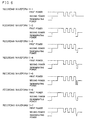
- FIG. 6 Various recording waveforms used in this embodiment will be described with Fig. 6.
- Fig. 6 In the figure there are shown typical recording waveform patterns used when a mark with a length of 6T is recorded.
- Recording waveform 11-1 is the case where a mark's rear end correction pulse train is not added.
- Recording waveform 11-2 is a recording waveform where immediately after a recording pulse train, laser light is irradiated for a period of 0.5T with a light reproducing power. After the irradiation, laser light irradiation is performed with a bias power.
- Recording waveform 11-3 is a recording waveform where immediately after a recording pulse train, power is reduced down to an intermediate level between a bias power and a light reproducing power and then laser light is irradiated for a period of 0.25T. Immediately after the irradiation, the power is reduced down to the light reproducing power and then there is added a mark's rear end correction pulse train where laser light is irradiated for a period of 0.25T. Thereafter, laser light irradiation is performed with a bias power.
- Recording waveform 11-4 is a recording waveform where immediately after a recording pulse train, laser light is irradiated for a period of 0.15T with a power higher than a bias power by 2 mW. Immediately after the irradiation, there is added a mark's rear end correction pulse train where laser light is irradiated for a period of 0.35T with a light reproducing power. Thereafter, laser light irradiation is performed with a bias power.
- Recording waveform 11-5 is a recording waveform where immediately after a recording pulse train, laser light is irradiated for a period of 0.2T with a light reproducing power. Immediately after the irradiation, laser light is irradiated for a period of 0.1T with a bias power. Immediately after the irradiation, there is added a mark's rear end correction pulse train where laser light is irradiated for a period of 0.2T with a light reproducing power. Thereafter, laser light irradiation is performed with a bias power.
- Recording waveform 11-6 is a recording waveform where immediately after a recording pulse train, power is continuously reduced from a bias power to a light reproducing power for a period of 0.2T and where there is added a mark's rear end correction pulse train where laser light is irradiated for a period of 0.3T with a light reproducing power. Thereafter, laser light irradiation is performed with a bias power.
- Recording waveform 11-7 is a recording waveform where immediately after a recording pulse train, power is continuously reduced from a bias power to a light reproducing power for a period of 0.25T. After the reduction, there is added a mark's rear end correction pulse train where power is continuously increased from a light reproducing power to a bias power for a period of 0.25T. Thereafter, laser light irradiation is performed with a bias power.
- the respective recording waveforms are shown in Table 21 and also the jitter values after 100 overwrite operations are shown in Table 21. Recording waveform Jitter Recording waveform 11-1 11.6% Recording waveform 11-2 9.6% Recording waveform 11-3 7.8% Recording waveform 11-4 8.4% Recording waveform 11-5 8.7% Recording waveform 11-6 8.0% Recording waveform 11-7 8.4%
- the symmetry between the front end portion and the rear end portion of the mark is controlled satisfactorily, so the jitter has further been improved in comparison with the recording waveform 14-2.
- the recording where jitters are satisfactory after 100 overwrite operations, becomes possible by adding a mark's rear end correction pulse train after a recording pulse train.
- the cooling power is a light reproducing power
- similar results were also obtained for the case where the cooling power was set between 0 and a power smaller than a bias power.
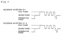
- FIG. 7 In the figure there are shown typical recording waveform patterns used when a mark with a length of 6T is recorded.
- Recording waveform 12-1 is the same recording waveform as the recording waveform 11-3 of the embodiment 1.
- the recording waveform 12-2 of the present invention where laser light irradiation is performed between a recording pulse train and a mark's rear end correction pulse train by a bias power, is a recording waveform where after a recording pulse train, laser light is irradiated for a period of 0.2T with a bias power. After the irradiation, the power is reduced to a power between a bias power and a reproducing power and then laser light is irradiated for a period of 0.25T. Immediately after the irradiation, the power is reduced to the reproducing power and then laser light is irradiated for a period of 0.25T. Thereafter, laser light irradiation is performed with the bias power.
- the recording where jitters are satisfactory after 100 overwrite operations, becomes possible by performing laser light irradiation between a recording pulse train and a mark's rear end correction pulse train by a bias power.
- the cooling power is a light reproducing power
- similar results were also obtained for the case where the cooling power was set between 0 and a power smaller than a bias power.
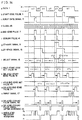
- FIG. 8 Various recording waveforms used in this embodiment will be described with Fig. 8.
- Fig. 8 In the figure there are shown typical recording waveform patterns used when a mark with a length of 6T is recorded. Note that measurement conditions are the same as the embodiment 1.
- the recording pulse train of each of recording waveforms 13-1, 2, and 3 is the aforementioned recording pulse train B of Fig. 4.
- the recording waveform 13-1 is the case where a mark's rear end correction pulse train is not added.
- the recording waveform 13-2 is a recording waveform where immediately after a recording pulse train, laser light is irradiated for a period of 0.5T with a light reproducing power. After the irradiation, laser light irradiation is performed with a bias power.
- the recording waveform 13-3 is a recording waveform where immediately after a recording pulse train, power is reduced down to an intermediate level between a bias power and a light reproducing power and then laser light is irradiated for a period of 0.25T. Immediately after the irradiation, the power is reduced down to the light reproducing power and then there is added a mark's rear end correction pulse train where laser light is irradiated for a period of 0.25T. Thereafter, laser light irradiation is performed with a bias power.
- Each of recording waveforms 13-4, 5, and 6 is the aforementioned recording pulse train C of Fig. 4.
- the recording waveform 13-4 is the case where no mark's rear end correction pulse train is added.
- the recording waveform 13-5 is the case where immediately after a recording pulse train, laser light is irradiated for a period of 0.5T with a light reproducing power. After the irradiation, laser light irradiation is performed with a bias power.
- the recording waveform 13-6 is the case where immediately after a recording pulse train, the same mark's rear end correction pulse train as the recording waveform 13-3 is added. Thereafter, laser light irradiation is performed with a bias power.
- Each of recording waveforms 13-7, 8, and 9 is the aforementioned recording pulse train D of Fig. 4.
- the recording waveform 13-7 is the case where no mark's rear end correction pulse train is added.
- the recording waveform 13-8 is the case where immediately after a recording pulse train, laser light is irradiated for a period of 0.5T with a light reproducing power. After the irradiation, laser light irradiation is performed with a bias power.
- the recording waveform 13-9 is the case where immediately after a recording pulse train, the same mark's rear end correction pulse train as the recording waveform 13-3 is added. Thereafter, laser light irradiation is performed with a bias power.
- the jitter is smaller in comparison with the recording waveform 13-2.
- the recording pulse train B of Fig. 4 in the case where a mark's rear end correction pulse train is added, the symmetry between the front end portion and the rear end portion of the mark is better, so the jitter has been improved.
- the recording where jitters are satisfactory after 100 overwrite operations, becomes possible by adding a mark's rear end correction pulse train to the recording pulse trains B, C, and D.
- the cooling power is a light reproducing power
- similar results were also obtained for the case where the cooling power was set between 0 and a power smaller than a bias power.
- the measurement conditions are the same as the embodiment 1. Also, in this embodiment the recording pulse train A of Fig. 4 was employed.
- Recording waveform 14-1 is a recording waveform where, immediately after a recording pulse train, power is reduced down to an intermediate level between a bias power and a light reproducing power regardless of the length of a mark to be recorded and then laser light is irradiated for a period of 0.25T. Immediately after the irradiation, the power is reduced down to the light reproducing power and then laser light is irradiated for a period of 0.25T. Thereafter, laser light irradiation is performed with a bias power.
- Recording waveform 14-2 has the same mark's rear end correction pulse train as the recording waveform 14-1.
- the start time of the mark's rear end correction pulse train is 0.8 when a mark with a length of 11T is recorded. As the mark length becomes shorter, the start time is quickened 0.1T at a time.
- a mark's rear end correction pulse train is added immediately after a recording pulse train. Thereafter, laser light irradiation is performed with a bias power.
- the recording where jitters are satisfactory after 100 overwrite operations, becomes possible by varying the mark's rear end pulse train start time in accordance with the length of a mark to be recorded.
- the cooling power is a light reproducing power
- similar results were also obtained for the case where the cooling power is between 0 and a power smaller than a bias power.
- a recording pulse train (the recording pulse train A of Fig. 4) was employed. Also, measurement conditions are the same as the embodiment 1.
- Fig. 9 Various recording waveforms used in this embodiment will be described with Fig. 9. Note that in the recording waveform 15-1 of Fig. 9 there is shown a typical recording pattern used when a mark with a length of 6T is recorded. Also, in the recording waveform 15-2 there are shown recording patterns used when, among marks with lengths of 3T through 11T, the marks with lengths of 3T through 5T, 10T and 11T are recorded.
- the recording waveform 15-1 is the same as the recording waveform 11-3 of the embodiment 1.
- the recording waveform 15-2 is a recording waveform where, immediately after a recording pulse train, the power is varied so as to be smaller as the length of a mark becomes shorter. Specifically, when the 3T mark is recorded, the power is set to a light reproducing power, and when the 4T mark is recorded, the power is set to a power greater than the light reproducing power by 1/8 of the power between a bias power and the light reproducing power. Thus, as the mark length becomes longer, the power is increased. Laser light is irradiated with the power for a period of 0.25T.
- the power is reduced down to the light reproducing power and then there is added a mark's rear end correction pulse where laser light is irradiated for a period of 0.25T. Thereafter, laser light irradiation is performed with a bias power.
- the cooling power is a light reproducing power
- similar results were also obtained for the case where the cooling power is between 0 and a power smaller than a bias power.
- the number of revolutions of the disk is 1000 rpm, and for an EFM signal, clock T was varied so that the shortest mark length becomes ⁇ m at all times.
- Recording waveform 16-1 is the case where no mark's rear end correction pulse train is added.
- Recording waveform 16-2 is the same as the recording waveform 11-3 of the embodiment 11.
- Recording waveform 16-3 also has the same mark's rear end correction pulse train as the recording waveform 11-3 of the embodiment 11, but as in the present invention, the start time of the mark's rear end correction pulse train is made shorter as the radial position of the disk gets closer to the inner circumferential side. Specifically, when the radius of the disk is between 23 and 34 mm, a mark's rear end correction pulse train is added immediately after a recording pulse train. When it is between 35 and 46 mm, the start time of the mark's rear end correction pulse train is delayed by 0.2T, and When it is between 47 and 57 mm, the start time of the mark's rear end correction pulse train is delayed by 0.5T.
- the respective recording waveforms are shown in Table 28 and also the jitter values after 100 overwrite operations are shown in Table 28. Note that measurements were made at each radius when the inner circumference is 26 mm, the middle circumference is 38 mm, and the outer circumference is 50 mm. Also, the respective linear velocities at the radii are about 2.7, 4.0, and 5.2 m/s.
- the recording where jitters are satisfactory after 100 overwrite operations, becomes possible by varying the start time of the mark's rear end pulse train in accordance with the radial position of the disk.
- the cooling power is a light reproducing power
- similar results were also obtained for the case where the cooling power is between 0 and a power smaller than a bias power.
- measurement conditions is the same as the embodiment 6.
- Fig. 10 Various recording waveforms used in this embodiment will be described with Fig. 10.
- Fig. 10 In the figure there are shown typical recording patterns used when a mark with a length of 6T is recorded. Also, in the recording waveform 17-2 there are shown recording waveforms used at the inner, middle, and outer circumferences of the disk.
- the recording waveform 17-1 is constant in the configuration of a mark's rear end correction pulse train regardless of the radial position of the disk, and the recording waveform is the same as the recording waveform 11-3 of the embodiment 1.
- the recording waveform 17-2 is a recording waveform where, immediately after a recoding pulse train, the power of the mark's rear end correction pulse train is varied so as to become smaller as the radial position of the disk gets closer to the inner circumferential side.
- the power after the recording pulse train is set to a power higher than a light reproducing power by 1 mW
- the power is set to between a bias power and a light reproducing power
- the power is set to a power lower than a bias power by 1 mW.
- laser light is irradiated for a period of 0.25T.
- the power is reduced down to the light reproducing power and then there is added a mark's rear end correction pulse where laser light is irradiated for a period of 0.25T. Thereafter, laser light irradiation is performed with a bias power.
- the symmetry between the front end portion and the rear end portion of the mark is better at the inner and outer circumferential portions for the recording waveform 17-2 of the present invention where, immediately after a recoding pulse train, the power of the mark's rear end correction pulse train is varied so as to become smaller as the radial position of the disk gets closer to the inner circumferential side. Therefore, the jitter has been improved in comparison with the recording waveform 17-1.
- the recording where jitters are satisfactory after 100 overwrite operations, becomes possible by varying the pulse configuration of the mark's rear end pulse train in accordance with the radial position of the disk.
- the cooling power is a light reproducing power
- similar results were also obtained for the case where the cooling power is between 0 and a power smaller than a bias power.
- data 1 is PWM data (Fig. 12a) having a high period and a low period which are two or more cycles of a clock in the length of clock unit.
- the high period of the data is recorded on a disk in correspondence with a mark, and the low period is recorded in correspondence with space.
- each width of a start edge pulse 3 and an end edge pulse 7 is assumed to be one cycle of the clock, and the width of a single burst pulse 27 is assumed to be a half cycle of the clock.
- the width of a cooling pulse is taken to be a half cycle of the clock, and the time between the end edge pulse of a recording pulse train and the start of laser light irradiation which is performed with a cooling power is also taken to be a half cycle of the clock.
- a mark/space length detection circuit 8 detects the space length at which the thermal interference between marks arises with high-density recording and also detects the mark/space length at which peak shift arises due to the frequency characteristic of a reproduction system.
- the start edge pulse 3 with a width of one cycle of the clock is generated at the start edge portion of the high period of the data 1 (Fig. 12b).
- a burst gate signal 5 with a length of the mark length reduced by three clocks is generated at the intermediate position of the mark. Note that when the mark length is 3 clocks or less, no burst gate signal is generated (Fig. 12c).
- the end edge pulse 7 with a width of one cycle of the clock is generated at the end edge portion of the high period of the data 1 (Fig. 12e).
- a mark/space length detection circuit 8 detects data having a two-clock width, that is, a 2T mark and a 2T space.
- a 2T-mark signal 9 with a two-clock width is generated so as to include the start edge pulse and the end edge pulse of the 2T mark (Fig. 12f).
- a 2T-space signal 10 with a four-clock width is generated so as to include the end edge pulse and the start edge pulse of both edges of the 2T space (Fig. 12g).
- the attributes of the start edge pulse 3 and the end edge pulse 7 are determined by the 2T-mark signal 9 and the 2T-space signal 10, and a select signal 12 is output. That is, data with both a 3T mark or more and a 3T space or more is referred to as "normal.” Data with both a 3T mark or more and a 2T space is referred to as 2Ts. Data with both a 2T mark and a 3T space or more is referred to as 2Tm. Data with both a 2T mark and a 2T space is referred to as 2Ts - 2Tm. Thus, the data is classified into 4 kinds of attributes (Fig. 12h).
- a single start edge set value is selected by the selector signal 12 from a plurality of start edge set values 13, that is, a start edge set value during "normal,” a start edge set value during 2Ts, a start edge set value during 2Tm, and a start edge set value during 2Ts - 2Tm, and then a selected start edge set value 15 is output.
- a start edge sample/hold circuit 16 only when the start edge pulse 3 appears, updating is performed, and when the start edge pulse 3 does not appear, a previous value is held and a held start edge set value 39 is output (Fig. 12i).
- the start edge pulse 3 is output as a start edge delay pulse 18 after the delayed time of a value based on the held start edge set value 39 (Fig. 12j).
- an end edge selector 20 a single end edge set value is selected from a plurality of end edge set values 19 by the select signal 12, and a selected end edge set value 21 is output.
- an end edge sample/hold circuit 22 only when the end edge pulse 7 appears, updating is performed, and when the end edge pulse 7 does not appear, a previous value is held and a held end edge set value 45 is output (Fig. 12k).
- the end edge pulse 7 is output as a delayed end edge pulse 24 after the delayed time of a value based on the held end edge set value 45 (Fig. 121).
- a cooling pulse is generated at the rise timing of the delayed end edge pulse by the amount of the half cycle of the clock (Fig. 12n).
- a cooling pulse 41 which is output from the cooling pulse generation circuit 36 is delayed by a constant quantity, and a cooling pulse signal 42 is output (Fig. 12o).
- the cooling pulse 42 is passed through an inverter 38 and is output as a delayed cooling pulse signal 43 where a high and a low were inverted (Fig. 12p).
- an OR gate 28 a logical sum is taken between the delayed start edge pulse 18 and the burst pulse 27, and a recording signal 29 is generated.
- a laser diode 35 is biased by a generating light current source 32 so that the diode 35 emits a reproducing light power for a phase change type optical disk.
- a bias level current source 31 and a recording level current source 30 are provided in parallel with the reproducing light current source 32, and if the current of the recording level current source 30 is turned on or off by a switch 33 and if the bias level current source 31 is turned on or off by a switch 34, the drive current of the laser diode 35 can be switched between three currents: a recording level current, a bias level current, and a reproducing light level current.
- a cooling pulse 48 is output from the cooling pulse generation circuit 46 at the same timing as the rise of the end edge pulse that was output from the end edge pulse generation circuit 6 (14f).
- the cooling pulse delay line 37 outputs a cooling pulse delayed by a constant quantity of delay (Fig. 14o).
- the disk storage unit in this embodiment adds laser light irradiation at a cooling power and respectively changes the positions of the start and end edges of a mark in accordance with the length of the mark to be recorded and the front and rear space lengths of the mark, whereby the mark and the space can be recorded in correspondence with data.
- start edge pulse and the end edge pulse has been taken to be a 1T width and the burst pulse a 0.5T width, it is also possible to select an optimum pulse width in accordance with the relative velocity between a recording film (or a storage medium) and an optical spot.
- cooling pulse width has been assumed to be 0.5T which is a constant value
- total energy can also be further reduced by varying the pulse with in accordance with mark length and mark spacing.
- the wavelength of the laser light is 680 nm and the NA of the objective lens of the optical head used for the recording and reproduction of the recording unit is 0.55.
- clock T is set so that the shortest mark length becomes 0.60 ⁇ m.
- ⁇ sum is the standard deviation of the sum of jitters between 2T and 8T
- Tw is the window width of the detecting system.
- the linear velocity is 4.0 m/s.
- the recording power where the C/N ratio saturates when a single frequency where the length of a mark becomes 0.6 ⁇ m is recorded, is taken to be a recording power.
- the cycle characteristic of the disk was judged by the number of cycles where the jitter value ⁇ sum/Tw (%) of the zero-cross point of a reproduced signal between 2T and 8T is less than 13%.
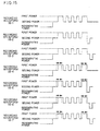
- Fig. 15 With Fig. 15, the recording waveforms used in this embodiment will be described. In the figure there are shown typical recording waveform patterns used when a 7T mark is recorded. For recording waveforms 18-1 through 18-3, the recording pulse train B of Fig. 4 is employed, and for recording waveforms 18-4 through 18-7, the recording pulse train C of Fig. 4 is employed.
- the recording waveform 18-1 is a recording pulse train where the width of the start edge pulse is 1.0T and the width of the end edge pulse is 1.0T and where between the start edge and end edge pulses, laser light is irradiated alternately for a period 0.5T with the second power and for a period 0.5T with the first power. In this case no cooling pulse is added.
- the recording waveform 18-2 is the case where immediately after the end edge pulse of the recording pulse train, a cooling pulse having an irradiation time of 0.5T at a cooling power is added to the aforementioned recording waveform 18-1 regardless of the length of a mark to be recorded.
- the recording waveform 18-3 is the case where a cooling pulse is added to the aforementioned recording pulse 18-1.
- the cooling pulse is a pulse where the irradiation time at a cooling power is 0.5T regardless of the length of a mark to be recorded and where the time between the fall of the end edge pulse of the recording pulse train and the start of the laser light irradiation which is performed with a cooling power is constant like 0.5T.
- the recording waveform 18-4 is the case where the positions of the start edge pulse and the end edge pulse of the recording pulse train are changed according to the length of the mark recorded with the recording waveform 18-1 and the front and rear spacings of the mark and where no cooling pulse is added.
- the recording waveform 18-5 is the case where immediately after the end edge pulse of the recording pulse train, a cooling pulse having an irradiation time of 0.5T at a cooling power is added to the aforementioned recording waveform 18-4 regardless of the length of a mark to be recorded.
- the recording waveform 18-6 is the case where a cooling pulse is added to the aforementioned recording pulse 18-4.
- the cooling pulse is a pulse where the irradiation time at a cooling power is 0.5T regardless of the length of a mark to be recorded and where the time between the fall of the end edge pulse of the recording pulse train and the start of the laser light irradiation which is performed with a cooling power is constant like 1.5T.
- the recording waveform 18-7 is the case where a cooling pulse is added to the aforementioned recording pulse 18-4.
- the cooling pulse is a pulse where the irradiation time at a cooling power is 0.5T regardless of the length of a mark to be recorded and where the irradiation start at a cooling power is delayed than the rise of the end edge pulse of a sub-pulse (a pulse between the start edge pulse and the end edge pulse) by a constant quantity such as 2.5T. That is, in this case the start time of the cooling pulse irradiation is based on a clock.
- the recording waveform 18-3 by performing laser light irradiation by a 0.5T bias power after the recording pulse train, the symmetry between the front edge portion and the rear edge portion of the mark is controlled more satisfactorily, so the jitter has become smaller in comparison with the recording waveform 18-2.
- the configuration of the mark can be more controlled than the case where the positions are not changed, so the jitter has become smaller.
- irradiation at a bias power is performed between the end edge pulse of the recording pulse train and the laser light irradiation which is performed with a bias power, whereby both the jitter value after 100 cycles and the number of cycles satisfying jitter ⁇ 13% are improved, and satisfactory values are obtainable in comparison with the recording waveform 18-5 where immediately after the recording pulse train, laser light irradiation is performed with a cooling power.
- the laser light irradiation at a bias power is put between the end edge portion of the recording pulse train where laser light irradiation is performed with a cooling power and the laser light irradiation which is performed with a cooling power, whereby the jitter value after 100 cycles is improved and satisfactory recording become possible even when a multi-cycle is performed.
- the recording method of the present invention a fluctuation in the length of a mark due to the thermal interference between marks is suppressed and the symmetry between the front end portion and the rear end portion of the mark becomes better. Therefore, the mark can be formed into a desired shape, the high-density requirement for optical disks can be met, and an enhancement in the quality of a reproduced signal can be realized even in the case where a method of rotating a disk is constant in angular velocity. Also, signal degradation due to thermal damage in the case of a multi-cycle can be alleviated and satisfactory cycle characteristics can be realized.
Claims (30)
- Optisches Informationsaufzeichnungsverfahren, bei dem das Laserlicht, das eine Mehrzahl von Leistungen aufweist, umgeschaltet und mit ihm ein optisches Speichermedium (61) bestrahlt wird, das eine dünne Speicherschicht (53) aufweist, das sich umkehrbar zwischen optisch erkennbaren Zuständen ändert, und bei dem ein digitales Signal, das modulierte Pulsbreiten aufweist, durch Verwenden eines Lichtbündels überschrieben wird, wobei in dem optischen Informationsaufzeichnungsverfahren eine Aufzeichnungsmarkierung durch Bestrahlen mit Laserlicht mit einer Aufzeichnungswellenform gebildet wird, die einen Aufzeichnungspulszug aufweist, der eine Mehrzahl von Pulsen umfasst, bei denen das Laserlicht zwischen einer ersten Leistung, die vorhergehend auf eine höhere Leistung als eine Aufzeichnungsleistung zur Aufzeichnung auf der dünnen Speicherschicht eingestellt wird, und einer zweiten Leistung moduliert wird, die vorhergehend auf eine geringere Leistung als die erste Leistung eingestellt wird, und auch nach dem Aufzeichnungspulszug einen Kühlpuls aufweist, der Laserlicht mit einer Kühlleistung ausstrahlt, die geringer als eine Vorleistung ist, bei der die Laserlichtleistung kleiner als die Aufzeichnungsleistung ist,
dadurch gekennzeichnet, dass
die Aufzeichnungswellenform eine Periode hat, bei der die Leistung des Laserlichts stufenweise zunehmend zwischen dem abfallendem Rand eines Endrandpulses des Aufzeichnungspulszugs und der Kühlleistung und/oder zwischen der Kühlleistung und der Vorleistung variiert wird. - Optisches Informationsaufzeichnungsverfahren nach Anspruch 1, bei dem Laserlichtbestrahlung bei der Vorleistung zwischen dem Aufzeichnungspulszug und dem Kühlpuls durchgeführt wird.
- Optisches Informationsaufzeichnungsverfahren nach Anspruch 1, wobei entweder die Laserlichtbestrahlungsanfangszeit bei der Kühlleistung in Bezug auf einen Endpunkt des Aufzeichnungspulszuges oder Laserlichtbestrahlungszeit bei der Kühileistung entsprechend der Länge der Aufzeichnungsmarkierung verändert wird.
- Optisches Informationsaufzeichnungsverfahren wie in Anspruch 3 angegeben, bei dem die Laserlichtbestrahlungsdauer bei der Kühlleistung länger gemacht wird, wenn eine kurze Aufzeichnungsmarkierung aufgezeichnet wird, als wenn eine lange Aufzeichnungsmarkierung aufgezeichnet wird.
- Optisches Informationsaufzeichnungsverfahren wie in Anspruch 3 angegeben, bei dem die Laserlichtbestrahlungsanfangszeit bei der Kühlleistung schneller gemacht wird, wenn eine kurze Aufzeichnungsmarkierung aufgezeichnet wird, als wenn eine lange Aufzeichnungsmarkierung aufgezeichnet wird.
- Optisches Informationsaufzeichnungsverfahren nach Anspruch 1, bei dem entweder die Laserlichtbestrahlungsanfangszeit bei der Kühlleistung in Bezug auf den Endpunkt des Aufzeichnungspulszugs oder die Laserlichtbestrahlungszeit bei der Kühlleistung nur verändert wird, wenn die Länge der Aufzeichnungsmarkierung kleiner als eine vorbestimmte Länge ist.
- Optisches Informationsaufzeichnungsverfahren nach Anspruch 1, bei dem eine Laserlichtbestrahlungsperiode bei der Vorleistung zwischen dem Aufzeichnungspulszug und der Laserlichtbestrahlung, die bei dem Kühlpuls durchgeführt wird, zur Verfügung gestellt wird;
Laserlichtbestrahlungsanfangszeit bei der Kühlleistung in Bezug auf einen Endpunkt des Aufzeichungspulszuges und Laserlichtbestrahlungszeit bei der Kühlleistung auf jeweils vorbestimmte Zeiten festgelegt sind; und
nur wenn die Länge der Aufzeichnungsmarkierungen kleiner als eine vorbestimmte Länge ist, die Laserlichtbestrahlung bei der Kühlleistung durchgeführt wird. - Optisches Informationsaufzeichnungsverfahren wie im Anspruch 7 angegeben, bei dem eine Laserlichtbestrahiung bei der Kühileistung nur durchgeführt wird, wenn die Länge der Aufzeichnungsmarkierung am kürzesten ist.
- Optisches Informationsaufzeichnungsverfahren nach Anspruch 1, bei dem das optische Speichermedium gedreht und bei einer konstanten Winkelgeschwindigkeit angetrieben wird, und
in einem Bereich des optischen Speichermediums innerhalb zumindest eines vorbestimmten Radius, wenn die Länge der Aufzeichnungsmarkierung kürzer als eine vorbestimmte Länge ist, ausgewählt wird, ob entweder die Laserlichtbestrahlungsanfangszeit bei dem Kühlleistungwert in Bezug auf einen Endpunkt des Aufzeichnungspulszugs beschleunigt wird, oder die Laserlichtbestrahlungsdauer bei dem Kühlleistungwert verlängert wird. - Optisches Informationsaufzeichnungsverfahren nach Anspruch 1, bei dem das optische Speichermedium gedreht und bei einer konstanten Winkelgeschwindigkeit angetrieben wird, und
nur wenn die Länge der Aufzeichnungsmarkierung kleiner als eine vorbestimmte Länge ist, die Laserlichtbestrahlungsanfangszeit bei der Kühlleistung in Bezug auf einen Endpunkt der Laserlichtbestrahlung bei der Aufzeichnungsleistung bzw. die Laserlichtbestrahlungszeit bei der Kühlleistung auf jeweils vorbestimmte Zeiten festgelegt werden, und
in einem Bereich des optischen Speichermediums (61) innerhalb zumindest eines vorbestimmten Radius eine Laserlichtbestrahlung bei der Kühlleistung nur ausgeführt wird, wenn die Länge der Aufzeichnungsmarkierung kürzer als eine vorbestimmte Länge ist. - Optisches Informationsaufzeichnungsverfahren wie im Anspruch 10 angegeben, bei dem eine Laserlichtbestrahlung bei der Kühlleistung nur durchgeführt wird, wenn die Länge der Aufzeichnungsmarkierung am kürzesten ist.
- Optisches Informationsaufzeichnungsverfahren nach Anspruch 1, wobei
unmittelbar nach dem Aufzeichnungspulszug ein Kühlpuls hinzugefügt wird, der einen Pulszug umfasst, der aus Laserlicht, das mindestens zwei verschiedene Leistungen hat, besteht, wobei die Laserlichtleistung weniger als die erste Leistung ist und wenigstens eine des Pulszugs des Kühlpulses eine Leistung ist, die kleiner als die Vorleistung ist. - Optisches Informationsaufzeichnungsverfahren nach Anspruch 1, bei dem ein Kühlpuls hinzugefügt wird, der eine Struktur hat, die eine Periode hat, bei der Laserlicht unmittelbar nach dem Aufzeichnungspulszug variiert wird und wobei Laserlicht auf eine Leistung verändert wird, die weniger als entweder die zweite Leistung oder die Vorleistung ist.
- Optisches Informationsaufzeichnungsverfahren wie in Anspruch 12 angegeben, bei dem:
der Kühlpuls aus vorhergehend festgesetzten dritten und vierten Leistungen des Laserlichts besteht;
die dritte Leistung eine Leistung ist, die größer als die vierte Leistung und kleiner als entweder die zweite Leistung oder die Vorleistung ist;
unmittelbar nach dem Aufzeichnungspulszug Laserlichtbestrahlung bei der dritten Leistung durchgeführt wird; und
unmittelbar nach de Laserlichtbestrahlung bei der dritten Leistung Laserlichtbestrahlung bei der vierten Leistung durchgeführt wird. - Optisches Informationsaufzeichnungsverfahren wie in Anspruch 12 angegeben, bei dem:
der Kühlpuls aus vorhergehend festgesetzten fünften und sechsten Leistungen des Laserlichts besteht;
die fünfte Leistung eine Leistung ist, die größer als die Vorleistung und die sechste Leistung eine Leistung ist, die kleiner als die Vorleistung ist;
unmittelbar nach dem Aufzeichnungspulszug Laserlichtbestrahlung bei der fünften Leistung durchgeführt wird; und
unmittelbar nach der Laserlichtbestrahlung bei der fünften Leistung Laserlichtbestrahlung bei der sechsten Leistung durchgeführt wird. - Optische Informationsaufzeichnungsverfahren wie in Anspruch 12 angegeben, bei dem der Kühlpuls aus vorhergehend festgesetzten siebten, achten und neunten Leistungen des Laserlichts besteht;
die siebte Leistung und die neunte Leistung beide kleiner als die achte Leistung sind und Leistungen sind, die kleiner als entweder die zweite Leistung oder die Vorleistung sind;
unmittelbar nach dem Aufzeichnungspulszug Laserlichtbestrahlung bei der siebten Leistung durchgeführt wird;
unmittelbar nach Laserlichtbestrahlung bei der siebten Leistung Laserlichtbestrahlung bei der achten Leistung durchgeführt wird; und
unmittelbar nach Laserlichtbestrahlung bei der achten Leistung Laserlichtbestrahlung bei der neunten Leistung durchgeführt wird. - Optische Informationsaufzeichnungsverfahren wie in Anspruch 13 angegeben, bei dem die Kühlleistung sowohl eine Periode hat, bei der Laserlicht unmittelbar nach dem Aufzeichnungspulszug auf eine Leistung, die entweder kleiner als die zweite Leistung oder die Vorleistung ist, variiert wird, als auch eine Periode hat, bei der ausgehend von der Leistung kleiner als entweder die zweite Leistung oder die Vorleistung die Laserlichtleistung auf entweder die zweite Leistung oder die Vorleistung variiert wird.
- Optisches Informationsaufzeichnungsverfahren wie in einem der Ansprüche 12 bis 17 angegeben, bei dem zwischen dem Aufzeichnungspulszug und dem Kühlpuls Laserlichtbestrahlung bei entweder der zweiten Leistung oder der Vorleistung durchgeführt wird.
- Optisches Informationsaufzeichnungsverfahren wie in einem der Ansprüche 12 bis 17 angegeben, bei dem entweder die Kühlleistunganfangszeit oder die Pulskonfiguration des Kühlpulses entsprechend der Länge der Aufzeichnungsmarkierung variiert wird.
- Optisches Informationsaufzeichnungsverfahren wie in einem der Ansprüche 12 bis 17 angegeben, bei dem, wenn das optische Speichermedium bei einer konstanten Winkelgeschwindigkeit rotiert wird, entweder die Kühlleistungzeit oder die Pulskonfiguration des Kühlpulses entsprechend der radialen Position des optischen Speichermediums variieren wird.
- Optisches Informationsaufzeichnungsverfahren, wie in einem der vorhergehenden Ansprüche 1 bis 20 angegeben, bei dem:
die Aufzeichnungsmarkierung durch Bestrahlen mit Laserlicht durch den Aufzeichnungspulszug gebildet wird, der von einer Mehrzahl von Pulsen gebildet ist, die zwischen der vorhergehend eingestellten ersten und zweiten Leistung moduliert werden, und
der Aufzeichnungspulszug bei der ersten Leistung, die konstant ist, an dem Anfangsrand des Aufzeichnungspulszugs bestrahlt und abwechselnd das Laserlicht umschaltet und mit ihm, das die erste und zweite Leistung aufweist, in einem von dem Anfangsrand des Aufzeichnungspulszugs verschiedenen Bereich mit einem kleineren Zyklus als ein Zyklus eines Datentakts bestrahlt. - Optisches Informationsaufzeichnungsverfahren, wie in einem der Ansprüche 1 bis 20 angegeben, bei dem die Aufzeichnungsmarkierung durch Bestrahlen mit Laserlicht durch den Aufzeichnungspulszug gebildet wird, der von einer Mehrzahl von Pulsen gebildet ist, bei denen das Laserlicht zwischen der vorhergehend eingestellten ersten und zweiten Leistung moduliert wird, und
der Aufzeichnungspulszug abwechselnd das Laserlicht, das die erste und zweite Leistung aufweist, mit einem kleineren Zyklus als ein Zyklus eines Datentakts umschaltet und mit ihm bestrahlt. - Optisches Informationsaufzeichnungsverfahren nach Anspruch 1, bei dem die Aufzeichnungsmarkierung durch Laserlichtbestrahlung durch einen Aufzeichnungspulszug gebildet wird, der von einer Mehrzahl von Pulsen gebildet ist, wobei Laserlicht zwischen vorhergehend festgesetzten ersten und zweiten Leistungen moduliert wird;
der Aufzeichnungspulszug mit der ersten Leistung, die konstant ist, bei dem Anfangsrand und Endrand des Aufzeichnungspulszugs bestrahlt, wenn die erste Leistung des Laserlichts größer als die zweite Leistung ist und zwischen dem Anfangsrand und dem Endrand des Aufzeichnungspulszuges der Aufzeichnungspulszug abwechselnd die erste Leistung und die zweite Leistung mit einem kleineren Zyklus als ein Zyklus des Datentakts umschaltet und mit ihr bestrahlt; und
unmittelbar nach dem Aufzeichnungspulszug Laserlichtbestrahlung mit einer Kühlleistung durchgeführt wird, die eine Leistung kleiner als die Vorleistung ist, wobei die Laserlichtleistung kleiner als die Aufzeichnungsleistung ist. - Optisches Informationsaufzeichnungsverfahren, wie Anspruch 23 angegeben, bei dem der Aufzeichnungspulszug ein Aufzeichnungspulszug ist, der die Positionen des Anfangsrands und des Endrands des Aufzeichnungspulszugs entsprechend der Länge der Aufzeichnungsmarkierung und des Abstand zwischen den Aufzeichnungsmarkierungen ändert.
- Optisches Informationsaufzeichnungsverfahren, wie in einem der Ansprüche 1 bis 20 angegeben, bei dem:
die Aufzeichnungsmarkierung durch Bestrahlen mit Laserlicht durch den Aufzeichnungspulszug gebildet wird, der von einer Mehrzahl von Pulsen gebildet ist, die zwischen den vorhergehend eingestellten ersten und zweiten Leistungen moduliert werden, und
der Aufzeichnungspulszug mit der ersten Leistung, die konstant ist, an dem Anfangsrand und dem Endrand des Aufzeichnungspulszugs bestrahlt, und der Aufzeichnungspulszug zwischen dem Anfangsrand und dem Endrand des Aufzeichnungspulszugs abwechselnd die erste Leistung und die zweite Leistung mit einem kleineren Zyklus als ein Zyklus eines Datentakts umschaltet und mit ihr bestrahlt. - Optisches Informationsaufzeichnungsverfahren, wie in einem der Ansprüche 1 bis 20 angegeben, bei dem:
die Aufzeichnungsmarkierung durch Bestrahlen mit Laserlicht durch den Aufzeichnungspulszug gebildet wird, der von einer Mehrzahl von Pulsen gebildet ist, die zwischen der vorhergehend eingestellten ersten und zweiten Leistung moduliert werden;
der Aufzeichnungspulszug mit der ersten Leistung, die konstant ist, an dem Anfangsrand und dem Endrand des Aufzeichnungspulszugs bestrahlt, und der Aufzeichnungspulszug zwischen dem Anfangsrand und dem Endrand des Aufzeichnungspulszugs abwechselnd die erste Leistung und die zweite Leistung mit einem kleineren Zyklus als ein Zyklus eines Datentakts umschaltet und mit ihr bestrahlt, und
der Aufzeichnungspulszug die Positionen des Anfangsrands und des Endrands des Aufzeichnungspulszugs entsprechend der Länge der Aufzeichnungsmarkierung und des Abstand zwischen den Aufzeichnungsmarkierungen ändert. - Optisches Informationsaufzeichnungsverfahren wie in Anspruch 26 angegeben, bei dem:
zwischen dem Aufzeichnungspulszug und der Laserlichtbestrahlung, die bei der Kühlleistung durchgeführt wird, eine Laserlichtbestrahlung bei der Vorleistung durchgeführt wird, und
die Zeit zwischen dem Anfang der Laserlichtbestrahlung an dem Endrandpuls des Aufzeichnungspulszugs und dem Anfang der Laserlichtbestrahlung bei der Kühlleistung konstant ist. - Optisches Informationsaufzeichnungsverfahren wie in Anspruch 26 angegeben, bei dem der Anfangszeitpunkt der Laserlichtbestrahlung bei der Kühlleistung auf dem Takt basiert.
- Optische Informationsspeichereinheit zur Durchführung des Verfahrens nach einem der Ansprüche 1 bis 28, die eine Plattenspeichereinheit ist, die eine hohe Periode von Daten auf einer Platte (61) in Entsprechung zu einer Markierung aofzeichnet und eine niedrige Periode der Daten in Entsprechung zu einem Zwischenraum zwischen den Markierungen aufzeichnet, wobei die optische Informationsspeichereinheit umfasst:
eine Anfangsrandpulserzeugungsschaltung (2), die einen Anfangsrandpuls, der eine konstante Breite aufweist, an einer Anfangsrandposition der hohen Periode der Daten erzeugt,
eine Burststeuererzeugungsschaltung (4), die ein Burststeuersignal an einer mittleren Position der Markierung erzeugt, wenn die hohe Periode der Daten lang ist, und die kein Burststeuersignal erzeugt, wenn die hohe Periode der Daten kurz ist,
eine Endrandpulserzeugungsschaltung (6), die einen Endrandpuls, der eine konstante Breite aufweist, an einer Endrandposition der hohen Periode der Daten erzeugt,
eine Markierungs-/Zwischenraumlängen-Erfassungsschaltung (8), die ein nT Markierungssignal erzeugt, das den Anfangsrandpuls und den Endrandpuls umfasst, wenn die hohe Periode der Daten n Takte aufweist, und die ein mT Markierungssignal erzeugt, das den Endrandpuls und den Anfangsrandpuls beider Ränder des Zwischenraums umfasst, wenn die niedrige Periode der Daten m Takte aufweist (wobei n und m natürliche Zahlen sind, die in einer Datenreihe vorhanden sind),
einen Codierer (11), der ein Auswählsignal erzeugt, das zur Steuerung einer Anfangsrandauswähleinrichtung (14), die später beschrieben werden soll und einer Endrandauswähleinrichtung (20), die später beschrieben werden soll, aus dem nT Markierungssignal und dem mT Markierungssignal erzeugt,
eine Kühlpulserzeugungsschaltung (36), die einen Kühlpuls erzeugt, der eine stufenweise Änderung der Laserlichtleistung zwischen dem abfallendem Rand eines Endrandpulses des Aufzeichnungspulszuges und einer Kühlleistung und/oder zwischen einer Kühlleistung und einer Vorleistung verursacht; und der eine konstante Breite von einem verzögerten Endrandpuls aufweist und von einer programmierbaren Endrandverzögerungsleitung (23), die später beschrieben werden soll, herkommt,
die Anfangsrandauswähleinrichtung (14), die einen aus einer Mehrzahl von Anfangsrandwerten durch das Auswählsignal auswählt und ausgibt,
eine Anfangsrand-Abtast-/Halteschaftung (16), die einen Anfangsrandeinstellwert, der von der Anfangsrandauswähleinrichtung (14) ausgegeben wird, nur aktualisiert, wenn der Anfangsrandpuls erscheint, und die einen vorhergehenden Wert hält, wenn kein Anfangsrandpuls erscheint,
eine programmierbare Anfangsrandverzögerungsleitung (17), die eine Verzögerungsgröße durch den Anfangsrandeinstellwert des Ausgangs der Anfangsrand-Abtast-/Halteschaltung (16) verändert und die einen verzögerten Anfangsrandpuls ausgibt, wobei der Anfangsrandpuls verzögert ist,
die Endrandauswähleinrichtung (20), die einen aus einer Mehrzahl von Endrandwerten durch das Auswählsignal auswählt und ausgibt,
eine Endrand-Abtast-/Halteschaltung (22), die einen Endrandeinstellwert, der von der Endrandauswähleinrichtung (20) ausgegeben wird, nur aktualisiert, wenn der Endrandpuls erscheint, und die einen vorhergehenden Wert hält, wenn kein Endrandpuls erscheint,
die programmierbare Endrandverzögerungsleitung (23), die eine Verzögerungsgröße durch den Endrandeinstellwert des Ausgangs der Endrand-Abtast-/Halteschaltung (22) verändert und dann den Endrandpuls verzögert und die einen verzögerten Endrandpuls ausgibt, wobei der Endrandpuls verzögert ist,
eine Kühlpulsverzögerungsleitung (37), die eine Verzögerungsgröße des Kühlpulses abändert und einen verzögerten Kühlpuls ausgibt,
ein UND-Glied (26), das ein logisches Produkt zwischen dem Burstpuls und dem Takt durchführt und einen Burstpuls ausgibt,
ein ODER-Glied (28), das eine logische Summe zwischen dem verzögerten Anfangsrandpuls, dem Burstpuls und dem verzögerten Endrandpuls durchführt und ein Aufzeichnungssignal ausgibt,
eine Umkehrschaltung (38), die das Kühlpulssignal umkehrt, das von der Kühlpulsverzögerungsleitung (37) herkommt,
eine Vorstromquelle (31), die einen Vorstrom einer Laserdiode (35), die später beschrieben werden soll, zuführt,
eine Aufzeichnungsstromquelle (30), die der Laserdiode einen Aufzeichnungsstrom parallel zu der Vorstromquelle (31) zuführt,
eine Lichtwiedergabestromquelle (32), die der Laserdiode (35) einen Lichtwiedergabestrom parallel zu der Vorstromquelle (31) zuführt,
einen Schalter (33), der den Strom der Aufzeichnungsstromquelle (30) durch den Aufzeichnungsstrom ein- und ausschaltet,
einen Schalter (34), der den Strom der Vorstromquelle (31) durch das Kühlpulssignal ein- und ausschaltet, und
die Laserdiode (35), die Plattensignale aufzeichnet und parallel durch die Vorstromquelle (31), die Aufzeichnungsstromquelle (30) und die Lichtwiedergabestromquelie (32) gesteuert wird. - Optische Informationsspeichereinheit zur Durchführung des Verfahrens nach einem der Ansprüche 1 bis 28, die eine Plattenspeichereinheit ist, die eine hohe Periode von Daten auf einer Platte (61) in Entsprechung zu einer Markierung aufzeichnet und eine niedrige Periode der Daten in Entsprechung zu einem Zwischenraum zwischen den Markierungen aufzeichnet, wobei die optische Informationsspeichereinheit umfasst:
eine Anfangsrandpulserzeugungsschaltung (2), die einen Anfangsrandpuls, der eine konstante Breite aufweist, an einer Anfangsrandposition der hohen Periode der Daten erzeugt,
eine Burststeuererzeugungsschaltung (4), die ein Burststeuersignal an einer mittleren Position der Markierung erzeugt, wenn die hohe Periode der Daten lang ist, und die kein Burststeuersignal erzeugt, wenn die hohe Periode der Daten kurz ist,
eine Endrandpulserzeugungsschaltung (6), die einen Endrandpuls, der eine konstante Breite aufweist, an einer Endrandposition der hohen Periode der Daten erzeugt,
eine Markierungs-/Zwischenraumlängen-Erfassungsschaltung (8), die ein nT Markierungssignal erzeugt, das den Anfangsrandpuls und den Endrandpuls umfasst, wenn die hohe Periode der Daten n Takte aufweist, und die ein mT Markierungssignal erzeugt, das den Endrandpuls und den Anfangsrandpuls beider Ränder des Zwischenraums umfasst, wenn die niedrige Periode der Daten m Takte aufiveist (wobei n und m natürliche Zahlen sind, die in einer Datenreihe vorhanden sind),
einen Codierer (11), der ein Auswählsignal erzeugt, das zur Steuerung einer Anfangsrandauswähleinrichtung (14), die später beschrieben werden soll, und einer Endrandauswähleinrichtung (20), die später beschrieben werden soll, aus dem nT Markierungssignal und dem mT Markierungssignal erzeugt,
eine Kühlpulserzeugungsschaltung (36), die einen Kühlpuls erzeugt, der eine stufenweise Änderung der Laserlichtleistung zwischen dem abfallenden Rand eines Endrandpulses des Aufzeichnungspulszugs und einer Kühlleistung und/oder zwischen einer Kühlleistung und einer Vorleistung verursacht, und der eine konstante Breite von einem Endrandpuls aufweist, der von der Endrandpulserzeugungsschaltung (6) herkommt,
die Anfangsrandauswähleinrichtung (14), die einen aus einer Mehrzahl von Anfangsrandwerten durch das Auswählsignal auswählt und ausgibt,
eine Anfangsrand-Abtast-/Halteschaltung (16), die einen Anfangsrandeinstellwert, der von der Anfangsrandauswähleinrichtung (14) ausgegeben wird, nur aktualisiert, wenn der Anfangsrandpuls erscheint, und die einen vorhergehenden Wert hält, wenn kein Anfangsrandpuls erscheint,
eine programmierbare Anfangsrandverzögerungsleitung (17), die eine Verzögerungsgröße durch den Anfangsrandeinstellwert des Ausgangs der Anfangsrand-Abtast-/Halteschaltung (16) verändert und die einen verzögerten Anfangsrandpuls ausgibt, wobei der Anfangsrandpuls verzögert ist,
die Endrandauswähleinrichtung (20), die einen aus einer Mehrzahl von Endrandwerten durch das Auswählsignal auswählt und ausgibt,
eine Endrand-Abtast-/Halteschaltung (22), die einen Endrandeinstellwert, der von der Endrandauswähleinrichtung (20) ausgegeben wird, nur aktualisiert, wenn der Endrandpuls erscheint, und die einen vorhergehenden Wert hält, wenn kein Endrandpuls erscheint,
die programmierbare Endrandverzögerungsleitung (23), die eine Verzögerungsgröße durch den Endrandeinstellwert des Ausgangs der Endrand-Abtast-/Halteschaltung (22) verändert und dann den Endrandpuls verzögert und einen verzögerten Endrandpuls ausgibt, wobei der Endrandpuls verzögert ist,
eine Kühlpulsverzögerungsleitung (37), die eine Verzögerungsgröße des Kühlpulses abändert, der von einer Kühlpulserzeugungsschaltung (36) ausgegeben wird, und einen verzögerten Kühlpuls ausgibt,
ein UND-Glied (26), das ein logisches Produkt zwischen dem Burstpuls und dem Takt durchführt und einen Burstpuls ausgibt,
ein ODER-Glied (28), das eine logische Summe zwischen dem verzögerten Anfangsrandpuls, dem Burstpuls und dem verzögerten Endrandpuls durchführt und ein Aufzeichnungssignal ausgibt,
eine Umkehrschaltung (38), die das Kühlpulssignal umkehrt, das von der Kühlpulsverzögerungsleitung (37) herkommt,
eine Vorstromquelle (31), die einer Laserdiode (35), die später beschrieben werden soll, einen Vorstrom zuführt,
eine Aufzeichnungsstromquelle (30), die der Laserdiode einen Aufzeichnungsstrom parallel zu der Vorstromquelle (31) zuführt,
eine Lichtwiedergabestromquelle (32), die der Laserdiode (35) einen Lichtwiedergabestrom parallel zu der Vorstromquelle (31) zuführt,
einen Schalter (33), der den Strom der Aufzeichnungsstromquelle (30) durch den Aufzeichnungsstrom ein- und ausschaltet,
einen Schalter (34), der den Strom der Vorstromquelle (31) durch das Kühlpulssignal ein- und ausschaltet, und
die Laserdiode (35), die Plattensignale aufzeichnet und parallel durch die Vorstromquelle (31), die Aufzeichnungsstromquelle (30) und die Lichtwiedergabestromquelle (32) gesteuert wird.
Applications Claiming Priority (7)
| Application Number | Priority Date | Filing Date | Title |
|---|---|---|---|
| JP26126295 | 1995-10-09 | ||
| JP26124695 | 1995-10-09 | ||
| JP26126295 | 1995-10-09 | ||
| JP26124695 | 1995-10-09 | ||
| JP19588096 | 1996-07-25 | ||
| JP19588096 | 1996-07-25 | ||
| EP96932820A EP0797193B1 (de) | 1995-10-09 | 1996-10-04 | Verfahren und vorrichtung zur aufnahme von optischer information |
Related Parent Applications (1)
| Application Number | Title | Priority Date | Filing Date |
|---|---|---|---|
| EP96932820A Division EP0797193B1 (de) | 1995-10-09 | 1996-10-04 | Verfahren und vorrichtung zur aufnahme von optischer information |
Publications (3)
| Publication Number | Publication Date |
|---|---|
| EP1020850A2 EP1020850A2 (de) | 2000-07-19 |
| EP1020850A3 EP1020850A3 (de) | 2000-08-16 |
| EP1020850B1 true EP1020850B1 (de) | 2002-01-09 |
Family
ID=27327159
Family Applications (5)
| Application Number | Title | Priority Date | Filing Date |
|---|---|---|---|
| EP00106331A Expired - Lifetime EP1018727B1 (de) | 1995-10-09 | 1996-10-04 | Aufnahmemethode und Aufnahmeeinheit für optische Information |
| EP00106335A Expired - Lifetime EP1020850B1 (de) | 1995-10-09 | 1996-10-04 | Aufnahmemethode und Aufnahmeeinheit für optische Information |
| EP99121145A Expired - Lifetime EP0991058B1 (de) | 1995-10-09 | 1996-10-04 | Aufnahmemethode für optische Information |
| EP99121158A Expired - Lifetime EP0991059B1 (de) | 1995-10-09 | 1996-10-04 | Aufnahmegerät für optische Information |
| EP96932820A Expired - Lifetime EP0797193B1 (de) | 1995-10-09 | 1996-10-04 | Verfahren und vorrichtung zur aufnahme von optischer information |
Family Applications Before (1)
| Application Number | Title | Priority Date | Filing Date |
|---|---|---|---|
| EP00106331A Expired - Lifetime EP1018727B1 (de) | 1995-10-09 | 1996-10-04 | Aufnahmemethode und Aufnahmeeinheit für optische Information |
Family Applications After (3)
| Application Number | Title | Priority Date | Filing Date |
|---|---|---|---|
| EP99121145A Expired - Lifetime EP0991058B1 (de) | 1995-10-09 | 1996-10-04 | Aufnahmemethode für optische Information |
| EP99121158A Expired - Lifetime EP0991059B1 (de) | 1995-10-09 | 1996-10-04 | Aufnahmegerät für optische Information |
| EP96932820A Expired - Lifetime EP0797193B1 (de) | 1995-10-09 | 1996-10-04 | Verfahren und vorrichtung zur aufnahme von optischer information |
Country Status (11)
| Country | Link |
|---|---|
| US (1) | US5745467A (de) |
| EP (5) | EP1018727B1 (de) |
| JP (2) | JP4145958B2 (de) |
| KR (1) | KR100456957B1 (de) |
| CN (3) | CN1146869C (de) |
| DE (5) | DE69612833T2 (de) |
| HK (1) | HK1005275A1 (de) |
| MX (1) | MX9704098A (de) |
| MY (1) | MY113691A (de) |
| TW (1) | TW359812B (de) |
| WO (1) | WO1997014143A1 (de) |
Families Citing this family (63)
| Publication number | Priority date | Publication date | Assignee | Title |
|---|---|---|---|---|
| DE69723931T2 (de) * | 1996-02-16 | 2004-06-17 | Koninklijke Philips Electronics N.V. | Verfahren und vorrichtung zur aufzeichnung auf einen optischen informationsträger |
| JPH10105970A (ja) * | 1996-09-27 | 1998-04-24 | Toshiba Corp | 光学的情報記録方法および装置 |
| KR100358507B1 (ko) * | 1996-12-20 | 2003-03-03 | 마쯔시다덴기산교 가부시키가이샤 | 광기록방법및광기록장치 |
| US6243339B1 (en) * | 1997-08-12 | 2001-06-05 | U.S. Philips Corporation | Method and device for writing optical record carriers |
| US7391698B2 (en) * | 1998-07-23 | 2008-06-24 | Samsung Electronics Co., Ltd. | Adaptive writing method for high-density optical recording apparatus and circuit thereof |
| US7158461B1 (en) * | 1997-12-30 | 2007-01-02 | Samsung Electronics Co., Ltd. | Adaptive writing method for high-density optical recording apparatus and circuit thereof |
| KR100354732B1 (ko) * | 1998-04-03 | 2002-11-18 | 삼성전자 주식회사 | 고밀도광기록기기를위한적응적인기록방법및그장치 |
| MY125795A (en) * | 1998-07-23 | 2006-08-30 | Samsung Electronics Co Ltd | Adaptive writing method for high-density optical recording apparatus and circuit thereof |
| TW468177B (en) * | 1998-08-04 | 2001-12-11 | Hitachi Ltd | Data storage method, data storage medium and data storage recording device |
| US6925040B1 (en) | 1998-08-04 | 2005-08-02 | Hitachi, Ltd. | Information recording method, information recording medium and information recording apparatus |
| JP3076033B1 (ja) | 1998-09-14 | 2000-08-14 | 松下電器産業株式会社 | 光学情報の記録再生装置および情報記録媒体 |
| JP4418114B2 (ja) * | 1999-03-19 | 2010-02-17 | パナソニック株式会社 | 光学的情報記録方法およびそれを用いた光学的情報記録装置 |
| TW561463B (en) * | 1999-03-30 | 2003-11-11 | Koninkl Philips Electronics Nv | Method and device for recording marks in an information layer of an optical record carrier |
| JP3762847B2 (ja) | 1999-04-13 | 2006-04-05 | 株式会社日立製作所 | 情報の記録方法及び情報の記録装置 |
| EP1936612B1 (de) * | 1999-05-19 | 2009-09-02 | Mitsubishi Kagaku Media Co., Ltd. | Aufzeichnen bei konstanter Winkelgeschwindigkeit |
| EP1199715A4 (de) * | 1999-05-31 | 2005-04-13 | Matsushita Electric Ind Co Ltd | Optisches informationsaufzeichnungsverfahren, optisches informationsaufzeichnungsgerät und optisches informationsaufzeichnungsmedium |
| JP4267852B2 (ja) * | 1999-07-15 | 2009-05-27 | コーニンクレッカ フィリップス エレクトロニクス エヌ ヴィ | 光学的記録担体の情報層にマークを記録するための方法及び装置、並びにそこでの使用に対する記録担体 |
| US7272094B2 (en) * | 1999-07-15 | 2007-09-18 | Koninklike Philips Electronics N.V. | Methods and devices for recording marks in an information layer of an optical record carrier, and record carriers for use therein |
| US6654325B1 (en) | 1999-08-09 | 2003-11-25 | Hitachi, Ltd. | Trial writing method and optical disk system using the same |
| JP2001067669A (ja) * | 1999-08-31 | 2001-03-16 | Sony Corp | 記録装置、記録方法 |
| KR100339478B1 (ko) * | 1999-09-18 | 2002-05-31 | 구자홍 | 광 기록매체의 최적 기록장치 및 기록방법 |
| TW518580B (en) * | 2000-05-11 | 2003-01-21 | Koninkl Philips Electronics Nv | Methods and devices for recording marks on a recording surface of an optical record carrier |
| US7239586B2 (en) * | 2000-07-28 | 2007-07-03 | Matsushita Electric Industrial Co., Ltd. | Optical disk device and recording power determining method |
| AU2001292339A1 (en) * | 2000-10-05 | 2002-04-15 | Matsushita Electric Industrial Co., Ltd. | Optical record medium, method for recording on optical record medium, and apparatus for recording on optical record medium |
| JP3793437B2 (ja) * | 2000-10-10 | 2006-07-05 | Tdk株式会社 | 光記録方法および光記録媒体 |
| US20020051415A1 (en) * | 2000-10-26 | 2002-05-02 | Matsushita Electric Industrial Co., Ltd. | Recording waveform generator and disk recording device |
| JP3969958B2 (ja) * | 2001-02-14 | 2007-09-05 | 株式会社リコー | 光情報記録方法 |
| JP4405115B2 (ja) | 2001-09-03 | 2010-01-27 | パイオニア株式会社 | 情報記録装置および情報記録方法 |
| TWI330363B (en) * | 2001-09-29 | 2010-09-11 | Samsung Electronics Co Ltd | Apparatus for forming first state and second state on optical recording medium |
| CN1248201C (zh) * | 2001-10-02 | 2006-03-29 | 松下电器产业株式会社 | 光学信息记录方法以及再生装置 |
| JP2003208713A (ja) * | 2002-01-16 | 2003-07-25 | Tdk Corp | 光記録媒体への情報記録方法、光記録媒体及び情報記録/再生装置 |
| US20050105437A1 (en) * | 2002-03-15 | 2005-05-19 | Akira Shimofuku | Recording apparatus and recording method |
| CN102176316A (zh) * | 2002-04-03 | 2011-09-07 | 松下电器产业株式会社 | 光盘驱动器、光学存储介质 |
| JP2004005872A (ja) * | 2002-04-09 | 2004-01-08 | Matsushita Electric Ind Co Ltd | 光ディスク原盤作製方法および光ディスクとその製造方法 |
| CN1221962C (zh) * | 2002-04-26 | 2005-10-05 | Tdk股份有限公司 | 光记录介质和在其中对数据进行光记录的方法 |
| US7369470B2 (en) * | 2002-05-20 | 2008-05-06 | Samsung Electronics Co., Ltd. | Method of recording erase pattern information on an optical recording medium, erasing information on the optical recording medium based on the erase pattern information, and optical recording medium therefor |
| KR100677104B1 (ko) * | 2002-05-20 | 2007-02-01 | 삼성전자주식회사 | 소거 패턴의 파워 정보가 저장된 광 기록 매체 |
| US8018817B2 (en) * | 2002-05-20 | 2011-09-13 | Samsung Electronics Co., Ltd. | Method of recording erase pattern information on an optical recording medium, erasing information on the optical recording medium based on the erase pattern information, and optical recording medium therefor |
| AU2003249430A1 (en) * | 2002-07-26 | 2004-02-23 | Koninklijke Philips Electronics N.V. | Method and device for optical recording and optical record carrier |
| JP4282285B2 (ja) * | 2002-08-12 | 2009-06-17 | Tdk株式会社 | 光記録媒体及び光記録方法 |
| US7474603B2 (en) * | 2002-09-04 | 2009-01-06 | Ricoh Company, Ltd. | Optical information recording method, apparatus, and medium, laser control circuit, wobble signal detection method, and servo signal detection method |
| JP2004103100A (ja) * | 2002-09-09 | 2004-04-02 | Tdk Corp | 光記録媒体への情報記録方法、情報記録装置及び光記録媒体 |
| JP2004171642A (ja) * | 2002-11-19 | 2004-06-17 | Tdk Corp | 光記録媒体、光記録方法及び光記録装置 |
| DE60315239T2 (de) | 2002-11-21 | 2008-04-17 | Matsushita Electric Industrial Co., Ltd., Kadoma | Verfahren und Vorrichtung, um einen Aufzeichnungspuls mittles Daten aus dem Benutzerfeld einer optischen Scheibe zu justieren. |
| US20050213467A1 (en) * | 2002-12-17 | 2005-09-29 | Yoshihiro Noda | Optical recording medium, and recording/reading method and recording/reading apparatus for optical recording medium |
| KR20040067778A (ko) * | 2003-01-23 | 2004-07-30 | 삼성전자주식회사 | 광 기록 매체, 이에 데이터를 기록하는 방법 및 그 장치 |
| WO2004066280A1 (en) * | 2003-01-23 | 2004-08-05 | Samsung Electronics Co., Ltd. | Optical recording medium, method and apparatus for recording data thereon |
| EP2299441A3 (de) | 2003-02-19 | 2011-07-13 | Victor Company Of Japan, Ltd. | Optisches Aufzeichnungsverfahren und optische Aufzeichnungsvorrichtung |
| KR100532955B1 (ko) * | 2003-06-16 | 2005-12-01 | 주식회사 하이닉스반도체 | 반도체 장치의 딜레이 공유 회로 |
| JP2005038559A (ja) * | 2003-07-18 | 2005-02-10 | Sony Corp | 情報記録装置及び方法 |
| JPWO2005041175A1 (ja) * | 2003-10-27 | 2007-08-23 | パイオニア株式会社 | 情報記録装置及び情報記録方法 |
| BRPI0506766A (pt) * | 2004-01-09 | 2007-05-22 | Matsushita Electric Ind Co Ltd | método e dispositivo para gravação óptica em meio de disco óptico |
| CN100356455C (zh) * | 2004-09-08 | 2007-12-19 | 上海乐金广电电子有限公司 | 相变型光盘信息记录的方法 |
| US20080137504A1 (en) * | 2004-10-19 | 2008-06-12 | Koninklijke Philips Electronics, N.V. | Method Of Writing Data On A Master Substrate For Optical Recording |
| EP1831873B1 (de) * | 2004-12-22 | 2010-11-24 | Koninklijke Philips Electronics N.V. | Gepulstes laserverfahren zur beschriftung von etiketten |
| WO2007105139A1 (en) * | 2006-03-13 | 2007-09-20 | Koninklijke Philips Electronics N. V. | Real time power control for optical recording drives |
| JP2007317343A (ja) * | 2006-04-28 | 2007-12-06 | Sharp Corp | 記録パラメータ設定装置、そのプログラムおよび該プログラムを記録したコンピュータ読取り可能な記録媒体、情報記録媒体、ならびに記録パラメータ設定方法 |
| CN101436414B (zh) * | 2006-04-28 | 2011-03-23 | 夏普株式会社 | 记录参数设定装置、方法和程序、记录有该程序的记录介质、信息记录介质、记录重放装置 |
| JP2007334921A (ja) | 2006-06-12 | 2007-12-27 | Hitachi Ltd | 記録方法、レーザ駆動装置及びそれらを用いた光ディスク装置 |
| TW200834558A (en) * | 2006-12-15 | 2008-08-16 | Taiyo Yuden Kk | Optical information recording device, optical information recording method, and optical information recording medium |
| US8848808B2 (en) * | 2007-03-01 | 2014-09-30 | Lightfleet Corporation | Time domain symbols |
| KR102544036B1 (ko) | 2021-09-01 | 2023-06-21 | 대한전열공업(주) | 브레이징 접합을 통한 중계기용 냉각장치의 제조방법 |
| KR102448582B1 (ko) | 2021-10-14 | 2022-09-29 | 대한전열공업(주) | 중계기용 유로형성 링의 조립장치 |
Family Cites Families (14)
| Publication number | Priority date | Publication date | Assignee | Title |
|---|---|---|---|---|
| JPS63113938A (ja) * | 1986-10-31 | 1988-05-18 | Matsushita Electric Ind Co Ltd | 情報の光学的記録方法 |
| US5257256A (en) * | 1987-04-24 | 1993-10-26 | Hitachi, Ltd. | Recording waveform for mark-length modulation optical recording |
| JP2574379B2 (ja) * | 1988-03-31 | 1997-01-22 | 松下電器産業株式会社 | 光学的情報記録消去方法 |
| JP2707774B2 (ja) * | 1989-12-13 | 1998-02-04 | 松下電器産業株式会社 | 光学情報の記録方法および記録装置 |
| JP2972899B2 (ja) * | 1991-01-24 | 1999-11-08 | 株式会社リコー | 光磁気記録方法 |
| JPH05120685A (ja) * | 1991-10-25 | 1993-05-18 | Olympus Optical Co Ltd | 光学式情報記録方法及びその装置 |
| EP0594425A3 (en) * | 1992-10-21 | 1996-10-09 | Nippon Kogaku Kk | Pulse train condition/heat shut off condition determination method and apparatus for optical recording, and optical recording method and apparatus |
| JPH06301978A (ja) * | 1992-10-28 | 1994-10-28 | Nikon Corp | 光記録のプリパルス条件及び熱遮断条件決定方法、 同決定装置、光記録方法及び光記録装置 |
| JPH06162507A (ja) * | 1992-11-24 | 1994-06-10 | Toshiba Corp | 情報記録方法および情報記録装置 |
| JP2684952B2 (ja) * | 1993-04-07 | 1997-12-03 | 松下電器産業株式会社 | ディスク記録方法およびディスク記録装置 |
| US5490126A (en) * | 1993-04-07 | 1996-02-06 | Matsushita Electric Industrial Co., Ltd. | Apparatus for recording and reproducing data on a disk |
| JP2679596B2 (ja) * | 1993-11-09 | 1997-11-19 | 松下電器産業株式会社 | ディスク記録方法およびディスク記録装置 |
| JP3231533B2 (ja) * | 1994-01-31 | 2001-11-26 | 株式会社日立製作所 | 光学的情報記録方法 |
| JPH0969246A (ja) * | 1995-08-30 | 1997-03-11 | Canon Inc | 光学的情報記録再生装置 |
-
1996
- 1996-10-04 WO PCT/JP1996/002897 patent/WO1997014143A1/ja active IP Right Grant
- 1996-10-04 DE DE69612833T patent/DE69612833T2/de not_active Expired - Lifetime
- 1996-10-04 JP JP51490497A patent/JP4145958B2/ja not_active Expired - Fee Related
- 1996-10-04 DE DE69618680T patent/DE69618680T2/de not_active Expired - Lifetime
- 1996-10-04 EP EP00106331A patent/EP1018727B1/de not_active Expired - Lifetime
- 1996-10-04 EP EP00106335A patent/EP1020850B1/de not_active Expired - Lifetime
- 1996-10-04 EP EP99121145A patent/EP0991058B1/de not_active Expired - Lifetime
- 1996-10-04 DE DE69618681T patent/DE69618681T2/de not_active Expired - Lifetime
- 1996-10-04 DE DE69618034T patent/DE69618034T2/de not_active Expired - Lifetime
- 1996-10-04 MX MX9704098A patent/MX9704098A/es not_active IP Right Cessation
- 1996-10-04 CN CNB961918284A patent/CN1146869C/zh not_active Expired - Fee Related
- 1996-10-04 EP EP99121158A patent/EP0991059B1/de not_active Expired - Lifetime
- 1996-10-04 EP EP96932820A patent/EP0797193B1/de not_active Expired - Lifetime
- 1996-10-04 KR KR1019970703863A patent/KR100456957B1/ko not_active IP Right Cessation
- 1996-10-04 DE DE69614005T patent/DE69614005T2/de not_active Expired - Lifetime
- 1996-10-08 TW TW085112297A patent/TW359812B/zh not_active IP Right Cessation
- 1996-10-08 MY MYPI96004162A patent/MY113691A/en unknown
- 1996-10-08 US US08/725,944 patent/US5745467A/en not_active Expired - Lifetime
-
1998
- 1998-05-21 HK HK98104407A patent/HK1005275A1/xx not_active IP Right Cessation
-
1999
- 1999-08-10 JP JP11226038A patent/JP2000155946A/ja active Pending
- 1999-09-30 CN CN99121073A patent/CN1128442C/zh not_active Expired - Fee Related
- 1999-09-30 CN CNB991210727A patent/CN1137473C/zh not_active Expired - Fee Related
Also Published As
Similar Documents
| Publication | Publication Date | Title |
|---|---|---|
| EP1020850B1 (de) | Aufnahmemethode und Aufnahmeeinheit für optische Information | |
| KR100426235B1 (ko) | 정보기록방법및정보기록장치 | |
| EP0830675B1 (de) | Verfahren und vorrichtung zur aufzeichnung auf einen optischen informationsträger | |
| US5412626A (en) | Method of recording optical information with selective correction in pulse waveform and a recording system therefor | |
| JP2001331936A (ja) | 光記録方法及び光記録媒体 | |
| JPH097176A (ja) | 光記録方法および光記録媒体 | |
| JP4063978B2 (ja) | 情報記録方法 | |
| JPH09282661A (ja) | 光記録方法、装置及び光記録媒体 | |
| KR950003182B1 (ko) | 광디스크 및 광학정보의 기록방법 | |
| US7260044B2 (en) | Recording method for a phase-change optical recording medium | |
| JP3277733B2 (ja) | 光ディスクへの光学的情報の記録方法および記録装置 | |
| JP3740151B2 (ja) | 光記録方法及び光記録装置 | |
| JPH04212735A (ja) | 光学情報の記録方法 | |
| JP3218235B2 (ja) | 記録装置 | |
| US7362682B2 (en) | Method for recording data in an optical recording disc and an apparatus for recording data in an optical recording disc | |
| US20050063272A1 (en) | Method for recording data in an optical recording disc and an apparatus for recording data in an optical recording disc | |
| JP3452050B2 (ja) | 情報の記録方法 | |
| US7680010B2 (en) | Method for recording information on optical recording medium | |
| JPH02165420A (ja) | 光情報記録方法 | |
| JP2000043414A (ja) | 相変化型光記録媒体 | |
| JPH0877600A (ja) | 光学的情報記録部材 | |
| JP2001229539A (ja) | 光記録方法および光記録媒体 | |
| JP2000185467A (ja) | 光情報記録媒体 | |
| JP2000155980A (ja) | 相変化型光記録媒体 | |
| KR19990074356A (ko) | 상변화 광디스크 |
Legal Events
| Date | Code | Title | Description |
|---|---|---|---|
| PUAI | Public reference made under article 153(3) epc to a published international application that has entered the european phase |
Free format text: ORIGINAL CODE: 0009012 |
|
| PUAL | Search report despatched |
Free format text: ORIGINAL CODE: 0009013 |
|
| AC | Divisional application: reference to earlier application |
Ref document number: 797193 Country of ref document: EP |
|
| AK | Designated contracting states |
Kind code of ref document: A2 Designated state(s): DE FR GB |
|
| AK | Designated contracting states |
Kind code of ref document: A3 Designated state(s): DE FR GB |
|
| 17P | Request for examination filed |
Effective date: 20000920 |
|
| 17Q | First examination report despatched |
Effective date: 20001030 |
|
| GRAG | Despatch of communication of intention to grant |
Free format text: ORIGINAL CODE: EPIDOS AGRA |
|
| AKX | Designation fees paid |
Free format text: DE FR GB |
|
| GRAG | Despatch of communication of intention to grant |
Free format text: ORIGINAL CODE: EPIDOS AGRA |
|
| GRAH | Despatch of communication of intention to grant a patent |
Free format text: ORIGINAL CODE: EPIDOS IGRA |
|
| GRAH | Despatch of communication of intention to grant a patent |
Free format text: ORIGINAL CODE: EPIDOS IGRA |
|
| GRAA | (expected) grant |
Free format text: ORIGINAL CODE: 0009210 |
|
| REG | Reference to a national code |
Ref country code: GB Ref legal event code: IF02 |
|
| AC | Divisional application: reference to earlier application |
Ref document number: 797193 Country of ref document: EP |
|
| AK | Designated contracting states |
Kind code of ref document: B1 Designated state(s): DE FR GB |
|
| REF | Corresponds to: |
Ref document number: 69618681 Country of ref document: DE Date of ref document: 20020228 |
|
| ET | Fr: translation filed | ||
| PLBE | No opposition filed within time limit |
Free format text: ORIGINAL CODE: 0009261 |
|
| STAA | Information on the status of an ep patent application or granted ep patent |
Free format text: STATUS: NO OPPOSITION FILED WITHIN TIME LIMIT |
|
| 26N | No opposition filed | ||
| PGFP | Annual fee paid to national office [announced via postgrant information from national office to epo] |
Ref country code: DE Payment date: 20120927 Year of fee payment: 17 Ref country code: FR Payment date: 20121018 Year of fee payment: 17 |
|
| PGFP | Annual fee paid to national office [announced via postgrant information from national office to epo] |
Ref country code: GB Payment date: 20121003 Year of fee payment: 17 |
|
| GBPC | Gb: european patent ceased through non-payment of renewal fee |
Effective date: 20131004 |
|
| REG | Reference to a national code |
Ref country code: DE Ref legal event code: R119 Ref document number: 69618681 Country of ref document: DE Effective date: 20140501 |
|
| PG25 | Lapsed in a contracting state [announced via postgrant information from national office to epo] |
Ref country code: GB Free format text: LAPSE BECAUSE OF NON-PAYMENT OF DUE FEES Effective date: 20131004 |
|
| REG | Reference to a national code |
Ref country code: FR Ref legal event code: ST Effective date: 20140630 |
|
| PG25 | Lapsed in a contracting state [announced via postgrant information from national office to epo] |
Ref country code: FR Free format text: LAPSE BECAUSE OF NON-PAYMENT OF DUE FEES Effective date: 20131031 Ref country code: DE Free format text: LAPSE BECAUSE OF NON-PAYMENT OF DUE FEES Effective date: 20140501 |