EP1002559A1 - Organe de commande en forme de pistolet et jeu electronique - Google Patents
Organe de commande en forme de pistolet et jeu electronique Download PDFInfo
- Publication number
- EP1002559A1 EP1002559A1 EP99921158A EP99921158A EP1002559A1 EP 1002559 A1 EP1002559 A1 EP 1002559A1 EP 99921158 A EP99921158 A EP 99921158A EP 99921158 A EP99921158 A EP 99921158A EP 1002559 A1 EP1002559 A1 EP 1002559A1
- Authority
- EP
- European Patent Office
- Prior art keywords
- gun
- game
- shaped controller
- controller
- shaped
- Prior art date
- Legal status (The legal status is an assumption and is not a legal conclusion. Google has not performed a legal analysis and makes no representation as to the accuracy of the status listed.)
- Granted
Links
Images


Classifications
-
- A—HUMAN NECESSITIES
- A63—SPORTS; GAMES; AMUSEMENTS
- A63F—CARD, BOARD, OR ROULETTE GAMES; INDOOR GAMES USING SMALL MOVING PLAYING BODIES; VIDEO GAMES; GAMES NOT OTHERWISE PROVIDED FOR
- A63F9/00—Games not otherwise provided for
- A63F9/02—Shooting or hurling games
- A63F9/0291—Shooting or hurling games with a simulated projectile, e.g. an image on a screen
-
- A—HUMAN NECESSITIES
- A63—SPORTS; GAMES; AMUSEMENTS
- A63F—CARD, BOARD, OR ROULETTE GAMES; INDOOR GAMES USING SMALL MOVING PLAYING BODIES; VIDEO GAMES; GAMES NOT OTHERWISE PROVIDED FOR
- A63F13/00—Video games, i.e. games using an electronically generated display having two or more dimensions
- A63F13/20—Input arrangements for video game devices
- A63F13/21—Input arrangements for video game devices characterised by their sensors, purposes or types
- A63F13/219—Input arrangements for video game devices characterised by their sensors, purposes or types for aiming at specific areas on the display, e.g. light-guns
-
- F—MECHANICAL ENGINEERING; LIGHTING; HEATING; WEAPONS; BLASTING
- F41—WEAPONS
- F41A—FUNCTIONAL FEATURES OR DETAILS COMMON TO BOTH SMALLARMS AND ORDNANCE, e.g. CANNONS; MOUNTINGS FOR SMALLARMS OR ORDNANCE
- F41A33/00—Adaptations for training; Gun simulators
-
- A—HUMAN NECESSITIES
- A63—SPORTS; GAMES; AMUSEMENTS
- A63F—CARD, BOARD, OR ROULETTE GAMES; INDOOR GAMES USING SMALL MOVING PLAYING BODIES; VIDEO GAMES; GAMES NOT OTHERWISE PROVIDED FOR
- A63F2300/00—Features of games using an electronically generated display having two or more dimensions, e.g. on a television screen, showing representations related to the game
- A63F2300/10—Features of games using an electronically generated display having two or more dimensions, e.g. on a television screen, showing representations related to the game characterized by input arrangements for converting player-generated signals into game device control signals
- A63F2300/1006—Features of games using an electronically generated display having two or more dimensions, e.g. on a television screen, showing representations related to the game characterized by input arrangements for converting player-generated signals into game device control signals having additional degrees of freedom
-
- A—HUMAN NECESSITIES
- A63—SPORTS; GAMES; AMUSEMENTS
- A63F—CARD, BOARD, OR ROULETTE GAMES; INDOOR GAMES USING SMALL MOVING PLAYING BODIES; VIDEO GAMES; GAMES NOT OTHERWISE PROVIDED FOR
- A63F2300/00—Features of games using an electronically generated display having two or more dimensions, e.g. on a television screen, showing representations related to the game
- A63F2300/10—Features of games using an electronically generated display having two or more dimensions, e.g. on a television screen, showing representations related to the game characterized by input arrangements for converting player-generated signals into game device control signals
- A63F2300/1062—Features of games using an electronically generated display having two or more dimensions, e.g. on a television screen, showing representations related to the game characterized by input arrangements for converting player-generated signals into game device control signals being specially adapted to a type of game, e.g. steering wheel
-
- A—HUMAN NECESSITIES
- A63—SPORTS; GAMES; AMUSEMENTS
- A63F—CARD, BOARD, OR ROULETTE GAMES; INDOOR GAMES USING SMALL MOVING PLAYING BODIES; VIDEO GAMES; GAMES NOT OTHERWISE PROVIDED FOR
- A63F2300/00—Features of games using an electronically generated display having two or more dimensions, e.g. on a television screen, showing representations related to the game
- A63F2300/80—Features of games using an electronically generated display having two or more dimensions, e.g. on a television screen, showing representations related to the game specially adapted for executing a specific type of game
- A63F2300/8076—Shooting
Definitions
- the present invention generally relates to a gun-shaped controller to be connected to electronic devices such as a video game machine, and particularly to a gun-shaped controller suitable for being used in gun games whereby characters displayed on a monitor screen are shot as targets.
- the present invention further relates to a game device comprising a gun-shaped controller imitating, for example, apelookas, rocket launchers, grenade launchers, and torpedoes, a game machine for processing game programs in accordance with instruction signals from the gun-shaped controller, and a display means for displaying pictures from this game machine.
- a gun-shaped controller imitating, for example, apelookas, rocket launchers, grenade launchers, and torpedoes
- a game machine for processing game programs in accordance with instruction signals from the gun-shaped controller
- a display means for displaying pictures from this game machine.
- This gun-shaped controller for a gun game comprises a trigger lever similar to an actual gun to which a player's finger is placed, and a light sensor for detecting the flashing light from a CRT screen is provided to the tip of this gun-shaped controller.
- the CRT screen instantaneously becomes a white screen in order to detect the impact position and emits flashing light.
- This white screen is realized by raster scanning.
- the light sensor detects this light and the controller detects the impact position by reading the X-Y coordinates of the raster scanning at such time. The game machine thereby judges whether the impact position coincides with the shooting target, and the game is progressed in accordance with a hit or a miss.
- the present situation is that other than the trigger lever mentioned above, provided is merely a button or the like for starting the game. Therefore, the mainstream of gun games using this controller is an orthodox shooting game whereby a player directly shoots at targets on the monitor screen.
- this type of game there is a shooting game where a character, such as a police officer, appears on the monitor screen in place of the player and successively shoots the enemies appearing on the screen. Nevertheless, this character is either fixed to a prescribed position within the screen or, even if it were able to move, the movement is predetermined by the program and the like. Thus, this type of game is also no better than a simple shooting game.
- game devices employing these gun-shaped controllers are also no better than a simple shooting game, and therefore lack amusement.
- An object of the present invention is to provide a gun-shaped controller capable of increasing the variation of the game software to be used and performing highly amusing games.
- Another object of the present invention is to provide a game device enabling a game development with enhanced amusement by employing the gun-shaped controller.
- Still another object of the present invention is to provide a game device enabling a virtual sensation in accordance with the situation during such game development.
- a gun-shaped controller for transmitting instruction signals pertaining to the game development with respect to the game image displayed on the screen of a display means, characterized in that the gun-shaped controller comprises integrally an operation key for transmitting, as a part of the aforementioned instruction signals, signals instructing a plurality of directions on the screen.
- the operation key is manually operable by the operator, and the instruction signals move the objects displayed on the screen in a plurality of directions.
- the operation key is a cross-shaped directional key capable of moving the displayed object upward, downward, leftward, and rightward as the plurality of directions.
- the displayed object is a character or cursor displayed on the screen.
- the gun-shaped controller comprises a gun barrel, grip to be held by the player, and trigger lever to be operated by the player, and the operation key may be arranged on the upper part of the grip.
- the gun-shaped controller comprises a gun barrel, grip to be held by the player, and trigger lever to be operated by the player, and the operation key may be arranged in the vicinity of the tip of the gun barrel.
- a gun-shaped controller for transmitting predetermined instruction signals comprising a gun barrel, grip to be held by the player, and trigger lever to be operated by the player, characterized in that the gun-shaped controller has a contact sensor for detecting the contact of the operator and is provided with a virtual bullet-loading portion for loading bullets virtually based on the contact state of the operator and the contact sensor.
- the virtual bullet-loading portion is provided to the bottom of the grip and may further comprise a sensor holder for movably mounting the contact sensor on the bottom of the grip.
- a gun-shaped controller for transmitting predetermined instruction signals comprising a gun barrel, grip to be held by the operator, and trigger lever to be operated by the operator, characterized in that the gun-shaped controller has a reload lever provided to the side of the gun barrel and arranged so as to be slidable on the side of the gun barrel, and a virtual bullet-loading portion for virtually loading bullets with the operation of the reload lever.
- a gun-shaped controller for transmitting predetermined instruction signals comprising a gun barrel, grip to be held by the operator, and trigger lever to be operated by the operator, characterized in that the gun-shaped controller is provided with a mounting portion for mounting a memory device.
- the memory device may be provided with a display screen for displaying information.
- the mounting portion may be provided to the tail protruding to the rear from the grip.
- a cable may be provided to the rear end of the grip.
- a cable may be provided to the rear end of the tail.
- a gun-shaped controller for transmitting predetermined instruction signals comprising a gun barrel, grip to be held by the operator, and trigger lever to be operated by the operator, characterized in that the gun-shaped controller is provided with a display screen for displaying information.
- a gun-shaped controller for transmitting predetermined instruction signals comprising a gun barrel, grip to be held by the operator, and trigger lever to be operated by the operator, characterized in that the lower face of the gun barrel is formed diagonally with respect to the lengthwise axis of the gun barrel from the lower face of the vicinity of the tip of the gun barrel to the portion to be connected with the trigger, and a directional key for instructing directions is provided to the upper part of the grip.
- an operation button may be provided to the upper part of the directional key.
- the directional key may be arranged on a face formed continuously to the rear face of the grip and inclined toward the tip of the gun barrel rather than the rear face.
- the directional key is positioned higher than, at the least, the tip of the trigger lever when the lengthwise axis of the gun barrel is to be the horizontal standard.
- the directional key is positioned approximately in the center of the widthwise direction of the gun when viewed from the rear of the gun.
- the mounting portion for mounting a peripheral is formed in the lengthwise axis direction of the gun barrel at the rear of the gun barrel and positioned at the upper part of the directional key.
- the peripheral is a memory device comprising a display screen for displaying information.
- the trigger lever is provided to a position easily operable with an index finger of the operator's hand holding the grip, and the directional key is provided to a position easily operable with the thumb of the operator's hand holding the grip.
- the operator may operate the gun-shaped controller single-handedly.
- a gun-shaped controller comprising a gun barrel, wherein the operator is able to conduct the operation of virtually firing a cannonball toward a game image displayed on the screen of the display means, characterized in that the gun-shaped controller further comprises a recoil mechanism for providing recoil to the gun barrel when the cannonball is fired.
- a game device for forming game images in a style wherein an enemy character and main character shown within the screen displayed on the display means battle each other, characterized in that the game device comprises a gun-shaped controller capable of transmitting, at the least, instruction signals for moving the main character on the screen and instruction signals for attacking a target on the game screen, and a game machine for processing a predetermined game program, moving the main character pursuant to the instruction signals from the gun-shaped controller, and progressing and developing the game.
- the game machine may comprise an image processing means for forming images of the main character successively moving along a predetermined course.
- the game machine may comprise an image processing means for forming game images from an objective viewpoint to view the main character when provided with instruction signals from the gun-shaped controller for moving the main character, and an image from the main character's viewpoint when battling an enemy character.
- the gun-shaped controller may comprise a gun barrel, grip to be held by the operator, trigger lever to be operated by the operator, light detecting means for obtaining light detection signals for detecting the position on the screen of the display means provided to the front portion of the gun barrel, directional key provided to the upper part of the gun barrel for instructing the main character to move left or right, signal processing means for transmitting predetermined instruction signals according to the operation and transmitting light detection signals from the light detecting means, supporting mechanism for rotatably supporting the gun barrel on a pedestal, and recoil mechanism for providing recoil to the gun barrel when the cannonball is fired.
- the recoil mechanism may comprise a movable mechanism for supporting the gun barrel and supporting mechanism reciprocally and biasing the gun barrel in one direction with an elastic member, rotation/reciprocation converter mechanism for supplying reciprocation to the movable mechanism, and driving source for rotatably driving the rotation/reciprocation converter mechanism.
- a plurality of operation buttons enabling a push operation of predetermined strokes at the rear of the gun barrel are arranged on the upper part of the pedestal supporting the gun barrel of the gun-shaped controller.
- the game machine may comprise a game processing means for determining the attacking power, destruction power and impact distance of the cannonball in accordance with the operation pattern of the plurality of operation buttons on the virtual bullet-loading portion, and progressing the game in accordance with such determination.
- the virtual bullet-loading portion comprises an operation button, to which a push operation of predetermined strokes is enabled, for transmitting operation signals of such push operation, locking mechanism for locking the operation button when the operation button is pushed a prescribed number of strokes, and unlocking mechanism for unlocking the operation button when a cannonball is fired by the operation of the trigger lever.
- the game machine successively forms three-dimensional explosion images of the course of the cannonball impacting, exploding, and disappearing in accordance with the lapse of time, and may comprise an image processing means for applying, to the three-dimensional explosion images showing the course of disappearance, two-dimensional explosion images similarly showing the course of disappearance as a semi-transparent texture.
- the game machine may comprise an image processing means which, when performing modifying processing to characters as a result of a cannonball explosion and the like, determines the polygon position of the character before modification and the polygon position of the character after modification, and performs interpolation processing of modifying the polygons therebetween based on polygon position information of both characters.
- the aforementioned game device comprises a housing containing the game machine and display means, and gun-shaped controller rotatably secured to a pedestal arranged in front of the display means of the housing via a supporting mechanism.
- the gun-shaped controller may be structured of a shape imitating a apelooka.
- indicators having the same color as the plurality of operation buttons provided to the pedestal supporting the gun barrel of the gun-shaped controller are provided in the same arrangement as the plurality of buttons, characterized in that the indicator corresponding to the operation button may light up when the operation button is pushed a predetermined number of strokes and locked by the locking mechanism, and the indicator corresponding to the operation button may turn off when the operation button is unlocked by the cannonball being fired with the operation of the trigger lever.
- the game machine may comprise an image processing means for forming image signals capable of respectively displaying a cursor, which displays the moving direction of the main character, on the left and right sides of the screen of the display means, changing the color of the cursor in accordance with the instruction signals and game development, and forming image signals capable of displaying the moving direction of the main character or outline of the situation of the main character during the game development using the combination of the colors thereof.
- the gun-shaped controller may comprise integrally an operation key for transmitting, as a part of the instruction signal, signals to move, at the least, the main character in a plurality of directions on the screen.
- the operation key of the gun-shaped controller is manually operable by an operator
- the instruction signal may be a signal for moving, at the least, the main character in a plurality of directions on the screen.
- the operation key of the gun-shaped controller may be a cross-shaped directional key capable of moving, at the least, the main character upward, downward, leftward, and rightward as the plurality of directions.
- Fig. 1 shows the exterior of a gun-shaped controller to be operated by a player and connected to a video game machine.
- the controller 1 is structured of a gun barrel 2 and a trigger 3 in order to imitate a gun.
- An artificial retinal unit 5 for reading the game image from the monitor screen (not shown) is provided at the tip of the gun barrel. Prescribed image processing is performed on the game image read here and input to the controller circuit 6 (not shown in Fig. 1) explained later.
- a trigger lever 7 structuring the operation portion of the controller is mounted on the trigger 3 so as to be movable with respect to the controller and operable with the player's finger.
- the trigger lever 7 may be structured of a switch for outputting on/off or a switch for outputting analog values in accordance with the control input.
- a start switch 8 a cross-shaped directional key 9 to be manually operated by a player as an operation key, and a reload switch 10 are provided to the upper part of the grip 4 of the controller 1, which corresponds to the hammer of an actual gun.
- the start switch 8 is for turning on the functioning of the controller upon starting a game.
- the cross-shaped directional key 9 is similar to a cross-shaped directional key provided on a general game controller and is used for arbitrarily changing the direction of the character with the player's finger operation and moving the cursor to an arbitrary position on a selective screen.
- the reload switch 10 is used for loading bullets into a gun, which is conducted by a player pressing this reload switch.
- the start switch 8, cross-shaped directional key 9, and reload switch 10 are connected to the controller circuit 6 as with the trigger lever 7, and the signals corresponding to the key operations are input to the control circuit.
- the gun-shaped controller provides various operations from the player's side by incorporating, in addition to the trigger lever 7, a cross-shaped directional key 9 to be operated by the player. This enables complex operations in a gun game and not just simply shooting enemies appearing on the screen.
- the player-side character a police officer character for example, may be displayed separately on a small screen within the monitor screen, moved in an arbitrary direction with the operation of the cross-shaped directional key 9, and the arrangement of background and enemies of the main screen may be changed in accordance therewith.
- This enables compatibility with complex shooting game software.
- options on characters and weapons to be used by the characters may be provided and arbitrarily selected with the operation of the cross-shaped directional key 9.
- this controller may be used for game software such as role-playing games and adventure games.
- the player may, for example, operate the start switch 8, cross-shaped directional key 9, and reload switch 10 with his/her thumb while operating the trigger lever with his/her index finger. That is, a so-called single-handed action may be used in operating this gun-shaped controller.
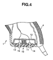
- the gun-shaped controller As shown in Fig. 1(c), the gun-shaped controller according to the present embodiment is provided with a slot 16 for inserting a below-described memory card with LCD, as a game peripheral, at the tail of the gun barrel of the controller.
- This slot 16 is formed along the lengthwise direction of the gun barrel, and a connector 17 to be connected to a memory card 15 is provided on the bottom thereof.
- a window 16a is formed on the upper part of this slot 16. From this window 16a, the LCD 19 of the memory card 15 inserted into this slot 16 can be viewed.
- the memory card 15 is mounted on the gun-shaped controller and is used, for example, as a memory for storing the hit/miss information of the shooting from the gun-shaped controller or as an external display means for notifying the player of such results.
- this memory card 15 may be used as a simple game device even if removed from the controller 1 by loading a mini game thereinto.
- this memory card 15 is provided with a small LCD portion 19 on the upper surface of its case 18.
- a cross-shaped directional key 20 and a plurality of operation buttons 21 are provided on the lower part thereof.
- An external connection terminal (not shown) for connection with a connector 17 on the controller side is provided on the upper inner side of the case 18. This external connection terminal is ordinarily covered with a cap 22 for protection from dust and the like, and such cap is removed upon the terminal being connected to the gun-shaped controller.
- Fig. 3 is a block diagram of the structure of the controller circuit 6 to which the operation information of the aforementioned various operation portions, namely the trigger lever 7, start switch 8, cross-shaped directional key 9, and reload switch 10, from the player are input.
- This Fig. 3 is a block diagram of the structure whereby the memory card 15 has been mounted.
- the controller circuit 6 is structured of a CPU 61 and a control unit 62, which is a gate alley.
- the CPU 61 is provided with, as a basic structure, a ROM 61b, RAM 61c, CPU 61d, and clock generator 61f.
- the CPU 61 is further provided with an input port 61a for inputting various operation signals from the trigger lever 7, start switch 8, and cross-shaped directional key 9, and an A/D converter 61e for converting analog image signals from the artificial retinal unit 5 into digital signals.
- the control unit 62 connected to the CPU 61 comprises a frame controller 62a, CPU interface 62b, register 62c, transmitter 62d, receiver 62e, and interface 62f which structures an information input/output port between a game machine and a memory card 15.
- the control circuit 23 of the memory card 15 is provided with, as a basic structure, a RAM 23b and CPU 23c.
- the control circuit 62 is further provided with an I/O port 23a for inputting various operation signals from the operation button 21 or LCD driving signals from the control circuit 6, and for outputting signals to the interface 62f of the LCD 19 and control circuit 6.
- the control circuit 23 and LCD 18 are driven with a battery 23d.
- a connector 17 is provided to the controller 1 for the installation of the memory card
- various functions such as saving and loading the player data by using the memory, may be provided to the controller via the aforementioned memory card 15.
- the LCD 19 of the memory card 15 for example, it is possible to display a simple map or to represent the position of the enemy not appearing on the monitor screen. It is also possible to use a memory card with built-in speakers and output game sounds therefrom and not only from the monitor.
- the gun-shaped controller of the present embodiment is thus compatible with highly entertaining game software.
- a reload unit 10 which is a virtual bullet-loading device using the contact sensor, may be provided on the grip 4.
- this reload unit 10 is structured of a sensor holder 13 supported by a unit case 12 via a spring 11 so as to be vertically movable with respect to the grip 4, and a pair of continuity-type contact sensors embedded under this holder 13. The continuity between the contact sensors is detected with the controller circuit 6.
- compatible game software may require the player to reload the bullets by hitting the butt of the gun with the palm of his/her hand upon running out of a prescribed number of ammunition.
- the game mode for which this unit 10 may be used is not limited to merely the contact/non-contact between the sensors, but may also be a type where the sensor continuity time of the player is counted, and the power or the number of loaded bullets is increased in proportion to the length of the continuity time.
- weapons such as the "Wave Motion Gun” of SF movies requiring an energy charge prior to firing may be used. It is therefore possible to provide a new type of amusement by being able to destroy all enemies on the screen with a single blast.
- a reload lever 24 is established slidably with respect to the side of the gun barrel 2 of the controller 1 as shown in Fig. 5(a).
- the player slides this reload lever 24 to reload bullets.
- the operation of the reload lever 24 by the player will be as though sliding a forearm of the gun barrel, in other words, it will be similar to an actual shooting action of pulling the sliding lever of an automatic-type gun.
- the cross-shaped directional key 9 is provided at the upper part of the grip 4 in Embodiment 1, in the present embodiment, the cross-shaped directional key 9 is arranged on the side in the vicinity of the tip of the gun barrel 2 as shown in Fig. 5(b). In this case, it is possible to operate the trigger lever 7 with one hand while operating the cross-shaped directional key 9 with the other hand, thereby enabling a secure operation of the gun-shaped controller with a double-handed action.
- the position of the slot 16 for inserting the memory card 15 to be mounted on the controller 1 is structured such that the tail potion 25 of the gun-shaped controller itself is extended in a lower diagonal direction and the slot 16 is provided on this tail and the memory slot 15 may be mounted at a position near the player's side. In such case, it is easier for the player to view the LCD of the memory card 15.
- the gun-shaped controller according to Embodiment 3 of the present invention is now explained with reference to Fig. 6.
- the controllers of the aforementioned embodiments all have connector cables 26 for connection with the game machine extending from the lower part of the grip 4, in the present embodiment, such cables 26 are extending from the tip of the controller's tail 25 additionally provided in a lower diagonal direction.
- a connector 17 is provided at the lower part of the slot 16 to be mounted from the upper part of the memory card 15.
- the memory card 15 is inserted from the upper part of the slot 16 and is connected to the connector 17.
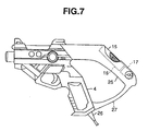
- the gun-shaped controller according to Embodiment 4 of the present invention is now explained with reference to Fig. 7.
- the grip and the tail are linked with a bridge 27.
- Figs. 8 through 10 show the exterior view of the gun-shaped controller to be operated by a player and connected to a video game machine.
- the controller 1 in the present embodiment also imitates a gun by being structured of a gun barrel 102, trigger 103, and grip 4 as shown in Fig. 8(b).
- An artificial retinal unit 105 for reading the game image from the monitor screen (not shown) is provided at the tip of the gun barrel 102. Prescribed image processing is performed on the game image read here and input to the built-in controller circuit 106. Explanation of the control circuit 106 is omitted as it is the same as the control circuit 6 described in Fig. 3.
- a trigger lever 107 structuring the operation portion of the controller is mounted on the trigger 103 so as to be movable with respect to the controller 101, and is operable with the player's finger.
- the single chain line shown as L in Fig. 8(b) is the lengthwise axis extending through the center of the artificial retinal unit 105 in the lengthwise direction of the gun barrel 102.
- the lower face 108 of the gun barrel 102 is structured diagonally with respect to the lengthwise axis L of the gun barrel, from the lower face position in the vicinity of the tip of the gun barrel to the connection point with the trigger 103.
- this structure is formed under the presumption that the player will hold the gun barrel 102 of the controller 101 with the other hand in order to improve the gun's precision, and the holdability of the gun barrel itself is improved by inclining the lower face 108.
- a player may shoot the gun while placing it directly on the video game machine 109 as shown in Fig. 11 (reference figure), which is not preferable in terms of the video game machine.
- Fig. 11 reference figure
- an operation face 111 is arranged on the upper part of the grip 104 of the controller 101 continuously to the rear face of the grip 104 and inclined toward the tip of the gun barrel rather than the rear face 110, and various buttons 113, 114 such as the cross-shaped directional key 112 and start button are provided thereto.
- the cross-shaped directional key 112 is similar to a cross-shaped directional key provided on a general game controller and is used for arbitrarily changing the direction of the character with the player's finger operation and moving the cursor to an arbitrary position on a selective screen. Considering the operability of this cross-shaped directional key 112, when the controller 101 is positioned so that the lengthwise axis L of the gun barrel becomes horizontal, the key 112 is position higher than the tip of the trigger lever 107 and, as shown in Fig. 8(c), is positioned approximately in the center of the gun barrel direction shown with the arrow W when viewed from the rear of the gun.
- the various buttons 113, 114 such as the start button are arranged to be symmetrical on the cross-shaped directional key 112 as positioned above.
- the various operation buttons 113, 114 such as the start button
- the muzzle of the gun naturally moves outside the screen (mainly downward) by the shift in finger movement pursuant thereto.
- the frequently used reload function may be achieved by the player shooting outside the screen as conventionally without depending on button operations.
- the various operation buttons 113, 114 and the cross-shaped directional key 112 are, in the same manner as the trigger lever 107, connected to the controller circuit 106, and signals corresponding to key operations are input to the control circuit 106.
- a slot (mounting portion) 116 for inserting a memory card (memory device) 15 with LCD, as a game peripheral, is provided to the tail portion 115 of the gun barrel of the controller 101.
- This slot 116 is formed in the lengthwise axis L direction of the gun barrel 2, and a connector 117 for connection with the memory card 15 is provided at the bottom portion thereof.
- a window 116a is formed on the upper part of the slot 116. From this window 116a, the LCD indicator 19 of the memory card 15 inserted into the slot 116 can be viewed.
- the external appearance of the gun is not ruined.
- a peripheral-mounting portion to the rear of the gun barrel 102, the player can easily insert the peripheral.
- a peripheral such as a vibration pack is mounted, it is possible to more effectively vibrate the gun in comparison to if it were to be mounted on the front of the gun.
- the present invention is not limited to the aforementioned embodiments and may be used in various other applications.
- controller 1, 101 is formed by imitating a short-nose type gun, it is not limited to such shape, and may be a normal-nose gun, or long-nose type guns such as shotguns and rifles.
- Figs. 12 through 22 are drawings to explain the hardware of the game device according to the embodiments of the present invention.
- Fig. 12 is a perspective view showing the overall game device.
- the game device is comprised of, as a basic structure, a game processing board 30, a housing 33 with a built-in monitor 31 which is a displaying means and speakers 32, 32, and a gun-shaped controller rotatably secured, via a supporting mechanism 36, to a pedestal 34 arranged in front of the monitor 31 of the housing 33.
- This game machine forms game images in the style wherein an enemy character shown within a screen displayed on the monitor 31 which is a display means, and a main character which moves and attacks within the screen of the monitor under the operation of the gun-shaped controller battle each other, and these game processing steps are performed with the aforementioned game processing board.
- the gun-shaped controller 35 supported rotatably on the pedestal 34 is formed, for example, in a shape imitating a apelooka as shown in Fig. 12, and the structure thereof is later explained.
- Operation buttons 37, 38, 39 are arranged on the upper part of the pedestal, at the rear of the gun barrel of the gun-shaped controller 35. These operation buttons 37, 38, 39 are enabled push operation with a predetermined number of strokes, and are colored, for example, as blue, yellow and red. These operation buttons 37, 38, 39 structure a part of the virtual bullet-loading portion (explained in detail later) capable of virtually loading bullets with the push operation of these operation buttons.
- Three indicators 41, 42, 43 are provided on the housing 33. These indicators 41, 42, 43 are the same color as the three operation buttons 37, 38, 39 provided on the pedestal and are provided in the same arrangement as such operation buttons. These indicators 41, 42, 43 either light up or turn off in accordance with the operation of the operation buttons 37, 38, 39. In other words, the indicators 41, 42, 43 light up in blue, yellow and red.
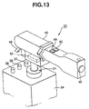
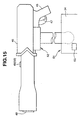
- Figs. 13 through 17 are used to explain the gun-shaped controller to be used with the game device and to the structural portions of this gun-shaped controller.
- Fig. 13 is a perspective diagram showing the portion relating to the gun-shaped controller and the pedestal.
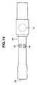
- Fig. 14 is a plan view showing the gun-shaped controller
- Fig. 15 is a side view showing the gun-shaped controller
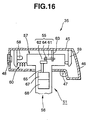
- Fig. 16 is a typical diagram showing the internal structure of the gun-shaped controller
- Fig. 17 is a plan view showing the enlarged rotation/reciprocation converter mechanism within the recoil mechanism inside the gun-shaped controller.
- the gun-shaped controller 35 comprises a gun barrel 45, grip 46 to be held by the operator, trigger lever 47 to be operated by the operator, light detecting means 48 for obtaining light detection signals for detecting the position on the screen of the monitor 31 provided to the front portion of the gun barrel 45, directional keys 49, 50 provided to the upper part of the gun barrel 45 for instructing the main character to move left or right, supporting mechanism 51 for rotatably supporting the gun barrel 45 on a pedestal 34, recoil mechanism 52 for providing recoil to the gun barrel 45 when the cannonball is fired, and signal processing means 53 for transmitting predetermined instruction signals according to the operation and transmitting light detection signals from the light detecting means 48.
- the recoil mechanism 52 of the gun-shaped controller 35 comprises a movable mechanism 54, rotation/reciprocation conversion mechanism 55, power source 56, and is structured as follows.
- a slide rail 57 reciprocally supports the gun barrel 45 and supporting mechanism 51. Stoppers 58, 59 are provided to the left and right of the gun barrel 45 in prescribed intervals as shown in and the slide rail moves between these stoppers 58, 59.
- the slide rail 57 comes in contact with the stopper 59 by being biased in one direction (leftward in Fig. 16) by a coil spring 60, which is an elastic member. Reciprocation from the rotation/reciprocation conversion mechanism 55 is supplied to this movable mechanism 52.
- the rotation/reciprocation conversion mechanism 55 is comprised of a link 61, cam 62 and other structural components.
- One edge of the link 61 is rotatably attached to an axis 63 secured to the gun barrel 45.
- the other edge of the link 61 is rotatably attached to the cam 62 with the axis 64.
- the cam 62 is secured to the rotational axis 63 of the power source 56.
- the power source 56 is comprised of a clutch 67 and motor 68.
- the cam 62 is secured to the output rotational axis 65 of the clutch 67.
- the clutch 67 and motor 68 are integrally formed, and, as well as being able to rotate the motor 68 by supplying power thereto, the power source is able to supply rotational power to the output rotational axis 65 by connecting the clutch 67 with operation signals.
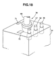
- Fig. 18 and Fig. 19 are diagrams for explaining the relationship of the mechanisms arranged on the pedestal. The pedestal is foremost explained.
- Fig. 18 is a perspective view showing an enlargement of the pedestal portion.
- provided to the pedestal 34 are a supporting mechanism 36, three operation buttons 37, 38, 39, and sensors 71, 72 for detecting the direction in which the gun barrel is facing (horizontal and vertical directions) from the movement of the axis 69 of the supporting mechanism 36.
- the operation buttons 37, 38, 39 are colored blue, yellow, and red.
- Fig. 19 is a concrete structural diagram of the virtual bullet-loading portion including the operation buttons.
- the virtual bullet-loading portions respectively including the operation buttons 37, 38, 39 are of the same structure, the virtual bullet-loading portion using operation button 37 is representatively explained.
- the virtual bullet-loading portion 75 comprises an operation button, to which push operation of predetermined strokes is enabled, for transmitting operation signals of such push operation, locking mechanism for locking the operation button when the operation button is pushed a prescribed number of strokes, and unlocking mechanism for unlocking the operation button when a cannonball is fired by the operation of the trigger lever, and is structured as follows.
- This operation button 37 comprises a hollow cylindrical shape, and is inserted into an engagement hole of the pedestal 34 from under and protrudes therefrom as shown in Fig. 19.
- a guide 79 is inserted inside the hollow cylinder of this operation button 37 and is movable in the vertical direction as shown in Fig. 19.
- a flange 80 is formed in the center of the cylinder of the operation button 37, and this flange is made to come in contact with the pedestal 34 and the wall 81.
- the lower part of the cylindrical operation button 37 is, as shown in the Fig. 19, provided with a large diameter portion 82 formed to be of a larger diameter in a prescribed size in comparison to the guide 82, and a coil spring 83 is arranged in the inner periphery thereof.
- the coil spring 83 is arranged between the upper end of this large diameter and the edge of the guide 79 as shown in Fig. 19, and pushes the operation button 37 upward.
- a switch 85 is arranged inside the guide 79, and this switch is turned on when the operation button 37 has been push-operated a predetermined number of strokes.
- the locking mechanism 76 and the unlocking mechanism 77 are structured as follows. That is, a groove 86 is formed between the flange 80 and the large diameter portion 82. To this groove 86, a guide roller 88 of a latch 87 is inserted, and the operation button is thereby locked.
- the latch 87 is rotatably secured to the pedestal 34 by the rotational axis 89.
- the latch 87 is biased toward the operation button 37 side by the spring 90. Therefore, when the groove 86 arrives at the guide roller 88 upon the operation button 37 being pushed, the latch 87 is pressed by the spring 90, and the guide roller 88 engages with the groove 86 and the operation button 37 is thereby latched.
- This latch 87 is linked to a solenoid 92. When this solenoid 92 is drawn in, the guide roller 88 disengages from the groove 86, and the operation button 37 thereby moves upward by the working of the coil spring 83.
- the switch 85 is connected to the signal processing circuit 58.
- This signal processing circuit 58 is connected to the game processing board 30.
- the solenoid 92 is connected to a solenoid driving circuit 93, and the solenoid 92 is excited by the drive of the solenoid driving circuit 93.
- the operation of this solenoid driving circuit 93 is controlled by the drive signals from the game processing board 30.
- Figs. 20 through 22 are diagrams for explaining the signal processing system of the game device.
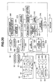
- Fig. 20 is a block diagram showing the structure of the game processing board and its peripheral circuit of the game device.
- this game device is comprised of, as a basic structure, a game processing board 30, input device 95 inclusive of the gun-shaped controller 35 for inputting instruction signals, output device 96 for applying recoil to the gun-shaped controller 35 and lighting and turning off the indicators 41, 42, 43, monitor 31, and speakers 32, 32.
- the input device is comprised of a light detecting means 48, preamp 97 for amplifying the detection signals of the light detection means 48, sensors 71, 72, directional keys 49, 50, trigger switch 98 for detecting the trigger of the trigger lever 47, virtual bullet-loading portions 75a, 75b, 75c, signal processing circuit 53 and auxiliary circuits thereof.
- the game processing board 30 comprises a CPU (central processing unit) 301 as well as a ROM 302, RAM 303, sound device 304, I/O interface 306, scroll data operation device 307, coprocessor (auxiliary operation processing device) 308, landform data ROM 309, geometrizer 310, shape data ROM 311, drawing device 312, texture data ROM 313, texture map RAM 314, frame buffer 315, image synthesizing device 316, and D/A converter 317.
- the sound circuit is comprised of an amplification circuit (AMP) 305 for amplifying sound signals from the sound device 304.
- AMP amplification circuit
- the CPU 301 is connected to the ROM 302 storing prescribed programs via a bus line, RAM 303 storing data, sound device 304, I/O interface 306, scroll data operation device 307, coprocessor 308, and geometrizer 310.
- the RAM 303 functions as a buffer, and performs writing of various commands (display of objects, etc.) to the geometrizer 310, matrix writing upon conversion matrix operation (e.g., scaling of explosion pictures explained later), and so on.
- the I/O interface 306 is connected to the input device 95 and output device 96. Thereby, the CPU 301 reads instruction signals and light signals of the input device 95 as digital quantity, and the signals generated by the CPU 301 are output to the output device.
- the output of the sound device 304 is connected to the speakers 32, 32 via an amplification circuit (AMP) 305, and the sound signals generated by the sound device 304 are provided to the speakers 32, 32 after amplification.
- AMP amplification circuit
- the CPU 301 reads operation signals from the gun-shaped controller 35 and virtual bullet-loading portion 75 based on the program built in the ROM 302, and landform data from the landform data ROM 309 or shape data from the shape data (three-dimensional data of "objects such as the main character and enemy character” and “backgrounds such as routes, landforms, skies, buildings”) from the ROM 311.
- the CPU 301 thereby performs, at the least, collision judgment between the landform and a cannonball fired from the gun held by the main character or the cannonball fired by the enemy character, pseudo semitransparent processing of the scroll screen, action calculation (simulation) of cars upon judgment processing of lock-on and the like, modification processing of the shape of objects, enlargement/reduction calculation of explosions and the like as special effects.
- Image processing of the main character simulates the movement of the main character in the virtual space according to the operation signals from the gun-shaped controller 35 or virtual bullet-loading portion 75.
- conversion matrix for converting these coordinate values into the visual field coordinate system and shape data (main character, enemy character, landform, buildings, etc.) are designated by the geometrizer 310.
- the landform data ROM 309 is connected to the coprocessor 308 and, therefore, predetermined landform data and the like are delivered to the coprocessor 308 (and CPU 301).
- the coprocessor 308 mainly performs judgment on the impact of the fired cannonball and, upon such judgment and simulation of the cannonball, mainly assumes the operation of floating decimal points.
- the collision judgment between the cannonball and enemy character or other buildings is performed by the coprocessor 308 and such judgment result is provided to the CPU 301.
- the calculation load of the CPU is decreased, and the collision judgment can be performed more rapidly.
- the geometrizer 310 is connected to the shape data ROM 311 and drawing device 312.
- the shape data ROM 311 stores in advance polygon shape data (three-dimensional data such as the main character, enemy character, landforms, and backgrounds structured of each of the vertexes), and this shape data is delivered to the geometrizer 310.
- the geometrizer 310 performs perspective conversion to the shape data designated by the conversion matrix sent from the CPU 301, and obtains data converted from the coordinate system within the three-dimensional space to the visual field coordinate system.
- the drawing device applies texture to the shape data of the converted visual field coordinate system and outputs this to the frame buffer 315.
- the drawing device 312 is connected to the texture ROM 313 and the texture map RAM 314, as well as to the frame buffer 315.
- polygon data shall mean a data group of relative or absolute coordinates of each vertex of a polygon (polygon: mainly triangles or quadrilaterals) structured of an aggregate of a plurality of vertexes.
- the landform data ROM 309 stored is polygon data set relatively roughly, which will suffice upon performing the collision judgment between the cannonball etc. fired from the cannon of the main character and the enemy character or point of impact.
- stored in the shape data ROM 311 is polygon data set accurately relating to the shapes forming the images of the main character, enemy character, explosion pictures, and backgrounds.
- the scroll data operation device 307 is for operating scroll screen data such as characters, and this operation device 307 and frame buffer 315 arrive at the display 6 via the image synthesizing device 316 and D/A converter 317.
- polygon screens (simulation effects) of the main character, enemy character and landform (background) temporarily stored in the frame buffer 315, and scroll screens such as character information necessary for display are synthesized according to priority, and the final frame image data is generated.
- This image data is converted to analog signals with the D/A converter 317 and sent to the monitor 31, and the game image is displayed in real time.
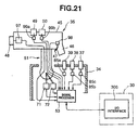
- Fig. 21 is a block diagram showing the structure of the input device mentioned above.
- a light detecting means 48 for detecting the position of impact preamp 97 for amplifying the light signal of this light detecting means 48
- directional keys 49, 50 and trigger lever 47.
- a trigger switch 98 for converting operation signals of such trigger lever to electric signals.
- directional keys 49, 50 are directional switches 99a, 99b for converting operation signals of such trigger lever to electric signals.
- the output of the preamp 97 is connected to the digital input port of the signal processing circuit 53.
- the output of the trigger switch 98 and the output of the directional switches 99a, 99b are respectively connected to the digital input port of the signal processing circuit 53.
- Operation buttons 37, 38, 39 are arranged on the pedestal 34.
- Switches 85a, 85b, 85c are provided to the operation buttons 37, 38, 39. These switches 85a, 85b, 85c are for converting the operation signals of the operation buttons 37, 38, 39 to electric signals.
- the switches 85a, 85b, 85c are connected to the digital input port of the signal processing circuit 53.
- Sensors 71, 72 are provided to the base of the supporting mechanism 51, and are capable of detecting the direction in which the gun-shaped controller is facing (horizontal direction, vertical direction) and converting such direction to analog signals. These sensors 71, 72 are connected to the analog port of the signal processing circuit 53.
- the signal processing circuit 53 may be of a one-chip CPU structure, and is capable of supplying to the I/O interface 306 of the game processing board 30 these input signals upon changing them into prescribed signal format.
- a one-chip CPU is a CPU structured in a single chip wherein an operation processing device, RAM, ROM, digital input port, analog input port, data output port, etc. are structured integrally.
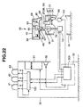
- Fig. 22 is a block diagram showing the structure of the output device mentioned above.
- the output device 96 is comprised of a clutch 67 and motor 68 of the recoil mechanism 55 of the gun-shaped controller and the driving circuits thereof, a solenoid 92 of the unlocking mechanism 77 of the virtual bullet-loading portion 75 and the driving circuit 152 thereof, indicators 1, 42, 43 arranged on the housing 33 and the driving circuits 153 thereof.
- These driving circuits 151, 152, 153 are connected to the I/O interface 306 of the game processing board 30, and form driving signals pursuant to orders from the game processing board 30.
- Fig. 23 is a diagram for explaining the operation of the virtual bullet-loading portion, and Figs. 23(a) through 23(c) respectively show the condition when the operation button is not pushed, is locked with the push-lock mechanism, and is unlocked with the unlocking mechanism.
- the operation button 37 in the end, becomes as shown in Fig. 23(a).
- Fig. 23(c) shows the moment the guide roller 88 on the tip of the latch 87 is removed from the groove 86 of the operation button 37.
- the operation is the sane for operation buttons 38, 39.
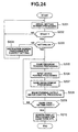
- Fig. 24 is a flowchart for explaining the main processing of the game device.
- the CPU 301 of the game processing board 30 performs the game processing as follows.
- the game processing board 30 forms the initial setup screen under the control of the CPU 301, and provides this to the monitor 31.
- set is necessary information for progressing the game such as the strength of the main character and the like (S201).
- the CPU 301 of the game processing board 30 judges whether or not the start button (not shown) has been operated (S202). If the start button has not been operated (S202; NO), it returns once again to the initial screen processing.
- the CPU 301 judges whether proper setting is made (S203). If not (S203; NO), the game processing board 30 forms display information for proper setting and provides this to the monitor 31, and returns once again to the initial screen processing.
- the CPU 301 judges that proper setting is made (S204; YES), the game is started. That is, the CPU 301 foremost reads the game program (S205) and reads each element of the input device 95 (S206). The CPU 301 then develops the game pursuant to the information from the game program and the input device 95 and provides necessary orders for developing the game to the coprocessor 308, geometrizer 310, operation device 307, etc (S207). Pursuant thereto, the image generating system (scroll data operation device 307, coprocessor 308, ..., D/A converter 317) on the game processing board 30, forms image signals based on the game development and provides this to the monitor 31 (S208).
- the sound generating system (sound device 304, electric amplifier circuit 305) on the game processing board generates and amplifies sound pursuant to the game development and provides this to the speakers 32, 32 (S208).
- the CPU 301 on the game processing board drives the recoil mechanism 52 via the I/O interface 306, lights up/turns off the indicators 41, 42, 43, and excites the solenoids 92a, 92b, 92c of the unlocking mechanism 77 (S208).
- the CPU 301 thereafter judges whether it is game over or time over (S209). If not over (S209; NO), it returns to the reading processing of the game program (S205) and continues the following processing steps.
- the game processing board 30 continues the processing steps of S205 to S209 above.
- the game processing board 30 judges that it is game over or time over (S209; YES), the game processing board 30 forms a game over or time over screen and provides this to the monitor 31 (S210).
- the image processing means forms images of the main character successively moving along a predetermined course. While the main character moves along such predetermined course, enemy characters appear, and the main character moving under the control of the gun-shaped controller 35 and these enemy characters battle each other with apelookas.
- the realized image processing means forms the game image 200 from an objective viewpoint in which the main character can be seen as shown in Fig. 25 when it is provided with instruction signals for moving the main character upon the directional key 49 or 50 of the gun-shaped controller 35 being operated.
- the image processing means forms image signals so as to display arrows (cursors) 180, 181 on the left and right sides of the screen 200. These arrows (cursors) 180, 181 show the operational state of the directional keys 49, 50 of the gun-shaped controller 35, that is, the moving direction of the main character 170.
- the image processing means further changes the color of the arrows (cursors) 180, 181 in accordance with instruction signals and the development of the game.
- the image processing means thereby forms image signals capable of displaying the movement direction of the main character and the outline of the situation of the main character (e.g., whether it is in an attackable condition) by the combination of the colors of these arrows (cursors) 180, 181.
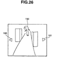
- the image processing means realized by the CPU 301 performing the aforementioned processing steps S205 to S209 forms an image 201 from the main character's viewpoint shown in Fig. 26 when battling an enemy character.
- the image processing means forms an image 201 wherein the main character is viewing such picture, the main character is not displayed within the image 201 as a matter of course.
- the image processing means realized by the CPU 301 performing the aforementioned processing steps S205 to S209 determines the attacking power, destruction power, impact distance of the cannonball in accordance with the operational patterns of the plurality of operation buttons 37, 38, 39 of the virtual bullet-loading portion 75, and progresses the game in accordance therewith.
- the game processing means progresses the game as follows as though a small rocket launcher has been loaded. Further, if the blue operation button 37 is pushed and locked and then the yellow operation button 38 is pushed and locked, the game processing means progresses the game as follows as though a medium rocket has been loaded. Moreover, if the blue operation button 37 is pushed and locked, the yellow operation button 38 is pushed and locked thereafter, and then the red operation button 39 is finally pushed and locked, the game processing means progresses the game as though a large rocket has been loaded.
- the game processing means progresses the game as though a small grenade has been loaded.
- the game processing means determines the attacking power, destruction power and impact distance of the cannonball pursuant to the push-lock order of the operation buttons 37, 38, 39 and progresses the game in accordance therewith.
- Fig. 27 is a diagram for explaining the processing of explosion pictures.
- the image processing means realized by the CPU 301 performing the aforementioned processing steps of S205 to S209 performs the processing steps as follows.
- the CPU 301 of the game processing board 30 instantaneously makes the screen of the monitor 31 bright when the trigger lever 47 of the gun-shaped controller 35 is pulled.
- the light detecting means of the gun-shaped controller detects this light and provides the light detection signals to the CPU 301 via the signal processing circuit 53 and I/O interface 306.
- the CPU 301 determines the impact position based on these light detection signals.
- the image processing means produces a semitransparent explosion picture with three-dimensional (3D) polygons 211 and erases the building 210 (S402).
- the image processing means then compulsorily makes semitransparent and erases the explosion picture made of 3D polygons 211 after a predetermined time (S403, S404).
- S403, S404 the outline of the 3D polygons 211 is extremely unnatural and conspicuous.
- an image 205 is formed (S405) wherein a naturally disappearing texture 213 is applied to the plane polygon 212 and layered on to the front of the 3D polygons 211.
- the image processing means performing the aforementioned processing steps of S401 to S406, it successively forms explosion images generated with 3D polygons 211 showing the course of the cannonball impacting, exploding, and disappearing in accordance with the lapse of time, and applies, to the plane polygon 212 placed in front of the explosion pictures of 3D polygons 211 showing the course of disappearance, two-dimensional explosion images similarly showing the course of disappearance as a semitransparent texture 213.
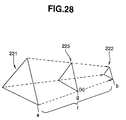
- Fig. 28 is a diagram for explaining the interpolation processing of image generation.
- the image processing means realized by the CPU 301 performing the aforementioned processing steps of S205 to S209, when performing modifying processing to characters as a result of a cannonball explosion and the like, determines the polygon 221 position of the character before modification and the polygon 222 position of the character after modification, and performs interpolation processing of modifying the polygons 223 therebetween based on polygon position information of both characters.
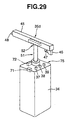
- Fig. 29 is a perspective diagram showing another structure of the gun-shaped controller.
- the difference between the gun-shaped controller 35a shown in this Fig. 29 and the gun-shaped controller 35 in Embodiment 6 is that the directional keys 49, 50 provided to the gun-shaped controller 35 in Embodiment 6 have been removed.
- the other structural components are the same, the explanation thereof is omitted.
- Fig. 30 is the flowchart showing the processing flow upon the aforementioned movement.
- Fig. 31 is a diagram showing an image example displayed on the screen during the course of the aforementioned processing flow.
- Figs. 31(a) through 31(f) are examples respectively showing the sight moving, sight stopping, sight having moved to the edge of the screen, screen scrolling, screen scrolling, and sight unable to move.
- Fig. 32 is a typical diagram showing the relationship between the position of the image memory storing the image data and the picture currently shown on the screen.
- the CPU 301 of the game processing board 30 reads detection signals (vertical direction on the screen (up and down the screen)) from the sensor 71 and the detection signals (left and right of the screen) from the sensor 72 of the gun-shaped controller 35a and moves the instruction indicator (sight: here, "sight” shall mean the telescopic sight of the gun-shaped controller 35a displayed on the screen 500) 551 displayed on the screen 500 in the up, down, right, and left directions thereof. And when the sight 551 moves to the edge of the screen 500, the CPU 301 realizes the image processing means for controlling the movement direction. In other words, the image processing means displays the moving direction indicator 552 (e.g., the arrow shown in Fig. 31(c)) and moves the main character a prescribed distance for each prescribed time frame.
- detection signals vertical direction on the screen (up and down the screen)
- detection signals left and right of the screen
- the instruction indicator shall mean the telescopic sight of the gun-shaped controller 35a displayed on the screen 500
- the CPU 301 realize
- the gun-shaped controller 35a is directed to the left side of the screen 500a, the sensor 72 detects this, and the detection signals are input to the CPU 301. Thereby, the CPU 301 moves the sight 551 within the screen 500a to the left side of the screen as shown in Fig. 31(a).
- the gun-shaped controller 35a is maintained at a certain position after being directed to the left side of the screen 500a, detection signals of movement from the sensor 72 are no longer detected, and the CPU 301 displays the sight 551 within the screen 500b as being still as shown in Fig. 31(b).
- the CPU 301 reads signals from the sensor 72 and moves the sight 551 within the screen 500 further to the left.
- the CPU 301 displays the image data within a prescribed area (area shown in solid lines with reference numeral 500) in the image memory 600 shown in Fig. 32 on the monitor 31 (refer to Figs. 12 and 20) as the image 500.
- the CPU 301 realizes the image processing means and the flowchart shown in Fig. 30 is performed by this image processing means (S400).
- the image processing means foremost performs the processing for displaying an arrow (movement direction indicator) in place of the sight (S401). Thereby, an arrow 552 is displayed on the screen 500c as shown in Fig. 31(c).
- the image processing means judges whether a prescribed time frame (approx. 2 seconds for example) has elapsed (S402).
- the image processing means judges that a prescribed time frame (approx. 2 seconds for example) has not elapsed (S402; NO), it returns to the processing of displaying the arrow (movement direction indicator) and performs once again arrow displaying processing (S401).
- a prescribed time frame approximately 2 seconds for example
- the image processing means displays the image data of the area (area shown in solid lines in reference numeral 500) of the image memory 600 as the image 500c.
- the image processing means judges that a prescribed time frame (approx. 2 seconds for example) has elapsed (S402; YES), the image processing means performs scroll processing (S404). Thereby, the arrow 552 shown in Fig. 31(d) remains displayed on the monitor 31 and a scroll screen 510s, in which a display picture 555 is beginning to appear, is displayed on the monitor 31.
- the image processing means displays the image data of the area (area shown with solid lines in reference numeral 510) within the image memory 600 as images 510s, 510A.
- the image 510s shown in Fig. 31(d) represents an image at the beginning of the scroll and the image 510A shown in Fig. 31(e) represents an image upon the completion of the scroll.
- the image processing means judges whether the sight has moved to the edge of the image memory 600 (S404). This judges whether the sight has reached the top/bottom edge or right/left edge of the image memory 600. Here, as the arrow 552 is facing the left side, the image processing means judges whether the sight has reached the left edge area (area shown with solid lines in reference numeral 530) of the image memory 600 as shown in Fig. 32 (S404).
- the image processing means judges that the sight is within a prescribed range (S404; YES), forms images in the area (area shown with two-point chained lines) in the vicinity of the center of the image memory 600 and displays this as the image 510A.
- the image processing means then returns to the initial arrow displaying processing (S401).
- the image processing means judges whether a prescribed time frame (approx. 2 seconds for example) has elapsed (S402). If the image processing means judges that a prescribed time frame (approx. 2 seconds for example) has not elapsed (S402; NO), it returns to the processing of displaying the arrow (movement direction indicator) and performs once again arrow displaying processing (S401).
- shown on the monitor 31 is the screen 510A displaying the arrow 552 at the left edge of the screen as shown in Fig. 31(e).
- the image processing means displays the image data of the area (area shown in solid lines in reference numeral 510) of the image memory 600 as the image 510A.
- the image processing means judges that a prescribed time frame (approx. 2 seconds for example) has elapsed (S402; YES), the image processing means performs scroll processing (S404). Thereby, the arrow 552 shown in Fig. 31(d) remains displayed on the monitor 31 and a scroll screen 510s, in which a display picture 555 is beginning to appear, is displayed on the monitor 31.
- the image processing means displays the image data of the area (area shown with solid lines in reference numeral 520s) within the image memory 600 as images 520s, 520A.
- the image 510s shown in Fig. 31(e) represents an image at the beginning of the scroll and the image 510A shown in Fig. 31(e) represents an image upon the completion of the scroll.
- the image processing means judges whether the sight has moved to the edge of the image memory 600 (S404). This judges whether the sight has reached the top/bottom edge or right/left edge of the image memory 600. Here, as the arrow 552 is facing the left side, the image processing means judges whether the sight has reached the left edge area (area shown with solid lines in reference numeral 530) of the image memory 600 as shown in Fig. 32 (S404).
- the image processing means judges that the sight is within a prescribed range (S404; YES), forms images in the area (area shown with two-point chained lines in reference numeral 530) in the vicinity of the center of the image memory 600 and displays this as the image 520A.
- the image processing means then returns to the initial arrow displaying processing (S401).
- the image scrolls for each prescribed time frame (2 seconds for example) and the main character is displayed each such occasion as though it moved a prescribed distance (3 meters for example) within the images 500, 510, 520.
- the image processing means displays the main character as though it moved a prescribed distance within the screen.
- the image processing means once again judges whether the sight moved to the edge of the image memory 600 per scroll processing (S404). That is, as the arrow 525 is facing the left side, the image processing means judges whether the sight has reached the left edge area (area shown with the two-point chain line in reference numeral 530) of the image memory 600 as shown in Fig. 32 (S404). Upon the image processing means performing scroll processing for each prescribed time frame, when the sight finally reaches the left edge area (area shown with the two-point chain line in reference numeral 530) of the image memory 600 (S404; NO), the image processing means performs the immovable display processing (S405).
- an image 530 as shown in Fig. 31(f) is displayed on the monitor 31.
- the image 530 shown in Fig. 31 is displayed in a stripe 560 with the overall left edge being a fixed color ("yellow” and "black” for example), and a sight 551 is displayed in place of the arrow 552.
- an arrow is displayed at the left edge of the monitor 31.
- a prescribed time frame lapsing in such display state it is possible to move the main character a prescribed distance.
- Fig. 33 is a diagram for explaining the relationship of the movement of the main character and the viewing point.
- Fig. 34 is a diagram explaining the situation where the relationship between the movement of the main character and the viewing point are displayed on the screen.
- reference numeral 700 is the viewing point of the main character 720.
- This viewing point 700 is for example the enemy character 710.
- the virtual camera 721 reads images of its periphery, including the enemy character, as image data.
- the main character 720a is viewing the viewing point 700.
- an image 800a As a state filmed by the virtual camera 721a, displayed on the monitor 31 is an image 800a as shown in Fig. 34(a).
- this image 800a for example, displayed are an enemy character 710 and buildings 711, 712 as shown in Fig. 34(a).
- the main character 720 has moved a prescribed distance for each prescribed time frame elapsed. For example, if the main character 720a moves along arrow j as shown in Fig. 33 and it is necessary to display an image seen from the main character 720a, the virtual cameral 721b, without losing the viewing point 700, reads other images and displays such images on the monitor 31. Therefore, an image 800b as shown in Fig. 34(b) is displayed on the monitor 31. Even in such case, the viewing point 700 does not change. Furthermore, as shown in Fig. 34(b), an enemy character 710, viewing point 700, and buildings 711, 712 are displayed in the image 800b.
- the viewing point 700 is always displayed without being changed in the objective viewpoint as well (here, "objective viewpoint” is not the viewpoint viewed by the main character, but an objective viewpoint in which the head or body of the main character may be viewed).
- the screen of the monitor is instantaneously brightened the moment the trigger is pulled, and the position within the screen of the monitor 31 is specified with the light detection means 48 of the gun-shaped controller 35, 35a. It is not, however, limited thereto.
- the position of the screen of the monitor 31 may be specified with the detection signals from the sensors 71, 72 of the gun-shaped controller 35, 35a, and the impact position may be determined pursuant to this specified data.
- the spirit of the invention described in the present application may be applied to, other than a gun-shaped controller, various controllers to be held such as a steering wheel-shaped controller for vehicle race games, a control lever-shaped controller for flight games, a fishing pole-shaped controller for fishing games, and so on.
- the present invention may be applied to various controllers in which the change of the controller's position, such as the direction of the muzzle, rotation of the handle, inclination/pull/push of the control lever, and inclination of the fishing pole, with respect to a standard such as the display screen of an electronic amusement device or game machine, is supplied to the data processing means of the electronic amusement device as the controlled variable, and which is held by a player substantially throughout the game play.
- the direction signal output means provided to this controller is capable of controlling the motion direction and movement direction of the displayed objects such as characters and backgrounds appearing in the game screen.
- the player may, for example, perform the game processing of operating the gun-shaped controller and firing virtual bullets used in the game toward the game screen.
- the gun-shaped controller of the present invention by forming a cross-shaped directional key 9, which is used as an operation key to be manually operated by an operator, integrally with the gun-shaped controller, enabled are complex movements such as moving the character on the screen or the character's visual field with this cross-shaped directional key in addition to the conventional action of shooting the targets on the screen.
- the gun-shaped controller is compatible with roll-playing games and adventure games.
- a gun-shaped controller capable of increasing the variation of the game software to be used and performing highly amusing games.
- the game device of the present invention provided is a game development with enhanced amusement by employing the gun-shaped controller, and a virtual sensation may be experienced in accordance with the situation within such game development.
Landscapes
- Engineering & Computer Science (AREA)
- Multimedia (AREA)
- Human Computer Interaction (AREA)
- General Engineering & Computer Science (AREA)
- Position Input By Displaying (AREA)
- Toys (AREA)
- Processing Or Creating Images (AREA)
Applications Claiming Priority (7)
| Application Number | Priority Date | Filing Date | Title |
|---|---|---|---|
| JP13086298 | 1998-05-13 | ||
| JP13086298 | 1998-05-13 | ||
| JP28651398 | 1998-10-08 | ||
| JP28651398 | 1998-10-08 | ||
| JP8500799 | 1999-03-26 | ||
| JP8500799 | 1999-03-26 | ||
| PCT/JP1999/002490 WO1999058214A1 (fr) | 1998-05-13 | 1999-05-13 | Organe de commande en forme de pistolet et jeu electronique |
Publications (4)
| Publication Number | Publication Date |
|---|---|
| EP1002559A1 true EP1002559A1 (fr) | 2000-05-24 |
| EP1002559A4 EP1002559A4 (fr) | 2003-03-26 |
| EP1002559B1 EP1002559B1 (fr) | 2005-12-07 |
| EP1002559B8 EP1002559B8 (fr) | 2006-04-26 |
Family
ID=27304730
Family Applications (1)
| Application Number | Title | Priority Date | Filing Date |
|---|---|---|---|
| EP99921158A Expired - Lifetime EP1002559B8 (fr) | 1998-05-13 | 1999-05-13 | Organe de commande en forme de pistolet |
Country Status (6)
| Country | Link |
|---|---|
| US (1) | US6672962B1 (fr) |
| EP (1) | EP1002559B8 (fr) |
| KR (1) | KR100564132B1 (fr) |
| DE (1) | DE69928751T2 (fr) |
| ES (1) | ES2257859T3 (fr) |
| WO (1) | WO1999058214A1 (fr) |
Cited By (10)
| Publication number | Priority date | Publication date | Assignee | Title |
|---|---|---|---|---|
| EP0978803A2 (fr) * | 1998-08-07 | 2000-02-09 | Sega Enterprises, Ltd. | Dispositif de traitement d'image et medium d'enregistrement d'information |
| EP1293238A1 (fr) * | 2001-09-14 | 2003-03-19 | Konami Corporation | Appareil de commande de jeu et dispositif pour introduire des signaux |
| EP1293237A3 (fr) * | 2001-09-06 | 2004-04-14 | McCauley, Jack | Procédé et dispositif pour l'interaction d'une arme optique avec un système de jeux par ordinateur |
| EP1900404A3 (fr) * | 2006-09-13 | 2008-04-16 | NAMCO BANDAI Games Inc. | Contrôleur de jeu et station d'accueil de chargement |
| WO2010080766A2 (fr) * | 2009-01-06 | 2010-07-15 | Immersion Corporation | Contrôleur de pistolet à activation haptique pour jeu programmable |
| GB2452175B (en) * | 2007-08-21 | 2012-12-05 | Benjamin Child | First person controller |
| ES2392531A1 (es) * | 2010-12-01 | 2012-12-11 | José Vicente AYLLÓN ALCÁZAR | Mando multifunción para videoconsola. |
| EP2569062A1 (fr) * | 2010-05-10 | 2013-03-20 | Sony Computer Entertainment America LLC | Manette sous la forme d'une arme à feu polymorphique |
| EP2902082A1 (fr) * | 2013-10-16 | 2015-08-05 | Paul Weatherstone | Dispositif d'entrée de commande pour jeux vidéo |
| WO2023214292A1 (fr) * | 2022-05-03 | 2023-11-09 | Janis Andersons | Dispositif de commande de jeu en forme de pistolet |
Families Citing this family (82)
| Publication number | Priority date | Publication date | Assignee | Title |
|---|---|---|---|---|
| US7749089B1 (en) | 1999-02-26 | 2010-07-06 | Creative Kingdoms, Llc | Multi-media interactive play system |
| US7878905B2 (en) | 2000-02-22 | 2011-02-01 | Creative Kingdoms, Llc | Multi-layered interactive play experience |
| US6761637B2 (en) | 2000-02-22 | 2004-07-13 | Creative Kingdoms, Llc | Method of game play using RFID tracking device |
| US7445550B2 (en) | 2000-02-22 | 2008-11-04 | Creative Kingdoms, Llc | Magical wand and interactive play experience |
| JP2001232056A (ja) * | 2000-02-23 | 2001-08-28 | Sega Corp | ビデオゲーム装置及び画像表現方法及びプログラム制御方法及び記憶媒体 |
| JP2002018128A (ja) * | 2000-07-10 | 2002-01-22 | Namco Ltd | ゲームシステム及び情報記憶媒体 |
| JP4433579B2 (ja) * | 2000-07-10 | 2010-03-17 | 株式会社バンダイナムコゲームス | ゲームシステム及び情報記憶媒体 |
| US7066781B2 (en) | 2000-10-20 | 2006-06-27 | Denise Chapman Weston | Children's toy with wireless tag/transponder |
| JP2002169461A (ja) * | 2000-11-30 | 2002-06-14 | Norio Watanabe | 語学レッスン装置 |
| JP4717266B2 (ja) * | 2001-06-12 | 2011-07-06 | 株式会社バンダイナムコゲームス | 画像処理装置、方法、プログラム、記録媒体およびポインティング装置 |
| US20030166415A1 (en) * | 2002-03-01 | 2003-09-04 | David Wu | Gun type main game machine |
| US6902483B2 (en) * | 2002-04-01 | 2005-06-07 | Xiao Lin | Handheld electronic game device having the shape of a gun |
| US6967566B2 (en) | 2002-04-05 | 2005-11-22 | Creative Kingdoms, Llc | Live-action interactive adventure game |
| US20070066396A1 (en) | 2002-04-05 | 2007-03-22 | Denise Chapman Weston | Retail methods for providing an interactive product to a consumer |
| US7674184B2 (en) | 2002-08-01 | 2010-03-09 | Creative Kingdoms, Llc | Interactive water attraction and quest game |
| US9446319B2 (en) | 2003-03-25 | 2016-09-20 | Mq Gaming, Llc | Interactive gaming toy |
| US7410404B2 (en) | 2003-07-29 | 2008-08-12 | Konami Digital Entertainment Co., Ltd. | Remote control toy system and driving device thereof |
| US7489299B2 (en) * | 2003-10-23 | 2009-02-10 | Hillcrest Laboratories, Inc. | User interface devices and methods employing accelerometers |
| WO2007143632A2 (fr) * | 2006-06-03 | 2007-12-13 | Eric Argentar | Dispositif de commande de jeu vidéo |
| US8070571B2 (en) * | 2003-12-11 | 2011-12-06 | Eric Argentar | Video game controller |
| US7510477B2 (en) | 2003-12-11 | 2009-03-31 | Argentar Eric J | Control apparatus for use with a computer or video game system |
| JP4673570B2 (ja) * | 2004-03-31 | 2011-04-20 | 株式会社セガ | 画像生成装置、画像表示方法及びプログラム |
| US7158118B2 (en) * | 2004-04-30 | 2007-01-02 | Hillcrest Laboratories, Inc. | 3D pointing devices with orientation compensation and improved usability |
| TWI376520B (en) | 2004-04-30 | 2012-11-11 | Hillcrest Lab Inc | Free space pointing devices and methods |
| US8629836B2 (en) | 2004-04-30 | 2014-01-14 | Hillcrest Laboratories, Inc. | 3D pointing devices with orientation compensation and improved usability |
| EP2343699A1 (fr) * | 2004-04-30 | 2011-07-13 | Hillcrest Laboratories, Inc. | Procédés et dispositifs permettant l'identification d'utilisateurs sur la base d'un tremblement |
| JP2007535774A (ja) * | 2004-04-30 | 2007-12-06 | ヒルクレスト・ラボラトリーズ・インコーポレイテッド | 自由空間ポインティングデバイスにおける意図的でない動きを除去するための方法およびデバイス |
| US8137195B2 (en) | 2004-11-23 | 2012-03-20 | Hillcrest Laboratories, Inc. | Semantic gaming and application transformation |
| WO2007011418A2 (fr) * | 2004-11-24 | 2007-01-25 | Dynamic Animation Systems, Inc. | Environnement de formation dirigee par un instructeur et interfaces associees |
| US7796116B2 (en) | 2005-01-12 | 2010-09-14 | Thinkoptics, Inc. | Electronic equipment for handheld vision based absolute pointing system |
| US8651964B2 (en) * | 2005-04-29 | 2014-02-18 | The United States Of America As Represented By The Secretary Of The Army | Advanced video controller system |
| US20070060392A1 (en) * | 2005-08-11 | 2007-03-15 | Sullivan Paul J | Game controller |
| JP4805633B2 (ja) * | 2005-08-22 | 2011-11-02 | 任天堂株式会社 | ゲーム用操作装置 |
| JP4703509B2 (ja) * | 2005-08-22 | 2011-06-15 | 任天堂株式会社 | ゲーム用操作装置およびゲームシステム |
| US7942745B2 (en) * | 2005-08-22 | 2011-05-17 | Nintendo Co., Ltd. | Game operating device |
| US8313379B2 (en) | 2005-08-22 | 2012-11-20 | Nintendo Co., Ltd. | Video game system with wireless modular handheld controller |
| US7927216B2 (en) * | 2005-09-15 | 2011-04-19 | Nintendo Co., Ltd. | Video game system with wireless modular handheld controller |
| JP4262726B2 (ja) | 2005-08-24 | 2009-05-13 | 任天堂株式会社 | ゲームコントローラおよびゲームシステム |
| US8870655B2 (en) | 2005-08-24 | 2014-10-28 | Nintendo Co., Ltd. | Wireless game controllers |
| US8308563B2 (en) * | 2005-08-30 | 2012-11-13 | Nintendo Co., Ltd. | Game system and storage medium having game program stored thereon |
| US8157651B2 (en) | 2005-09-12 | 2012-04-17 | Nintendo Co., Ltd. | Information processing program |
| US8568213B2 (en) | 2005-11-04 | 2013-10-29 | Mattel, Inc. | Game unit with controller-determined characters |
| US20070113207A1 (en) * | 2005-11-16 | 2007-05-17 | Hillcrest Laboratories, Inc. | Methods and systems for gesture classification in 3D pointing devices |
| JP4172652B2 (ja) * | 2005-12-06 | 2008-10-29 | 株式会社タイトー | ビデオ式シューティングゲーム装置 |
| JP4530419B2 (ja) * | 2006-03-09 | 2010-08-25 | 任天堂株式会社 | 座標算出装置および座標算出プログラム |
| JP4151982B2 (ja) * | 2006-03-10 | 2008-09-17 | 任天堂株式会社 | 動き判別装置および動き判別プログラム |
| JP4684147B2 (ja) * | 2006-03-28 | 2011-05-18 | 任天堂株式会社 | 傾き算出装置、傾き算出プログラム、ゲーム装置およびゲームプログラム |
| JP4989105B2 (ja) * | 2006-05-09 | 2012-08-01 | 任天堂株式会社 | ゲームコントローラ |
| US8913003B2 (en) | 2006-07-17 | 2014-12-16 | Thinkoptics, Inc. | Free-space multi-dimensional absolute pointer using a projection marker system |
| JP5051822B2 (ja) | 2006-08-02 | 2012-10-17 | 任天堂株式会社 | 汎用遠隔制御機能を備えたゲーム装置 |
| US9151564B1 (en) * | 2006-08-15 | 2015-10-06 | Triggermaster, Inc. | Firearm trigger pull training system and methods |
| US8777620B1 (en) | 2006-08-15 | 2014-07-15 | Triggermaster, Inc. | Firearm trigger pull training system and methods |
| US8556628B1 (en) | 2006-08-15 | 2013-10-15 | Malcom E. Baxter | Shooting training device |
| JP2008073184A (ja) * | 2006-09-20 | 2008-04-03 | Namco Bandai Games Inc | プログラム、情報記憶媒体及びゲーム装置 |
| US8721460B2 (en) * | 2007-01-04 | 2014-05-13 | Jakks Pacific, Inc. | Toy laser gun and laser target system |
| JP5127242B2 (ja) | 2007-01-19 | 2013-01-23 | 任天堂株式会社 | 加速度データ処理プログラムおよびゲームプログラム |
| US9176598B2 (en) | 2007-05-08 | 2015-11-03 | Thinkoptics, Inc. | Free-space multi-dimensional absolute pointer with improved performance |
| US7860676B2 (en) | 2007-06-28 | 2010-12-28 | Hillcrest Laboratories, Inc. | Real-time dynamic tracking of bias |
| JP2007307412A (ja) * | 2007-08-20 | 2007-11-29 | Sony Corp | 電子機器及び電子機器の画像生成方法 |
| JP2007307413A (ja) * | 2007-08-20 | 2007-11-29 | Sony Corp | 画像処理装置及び方法 |
| JP4228022B1 (ja) | 2007-09-19 | 2009-02-25 | 株式会社コナミデジタルエンタテインメント | ゲーム装置、ゲーム装置の制御方法及びプログラム |
| US8359545B2 (en) | 2007-10-16 | 2013-01-22 | Hillcrest Laboratories, Inc. | Fast and smooth scrolling of user interfaces operating on thin clients |
| US20090143143A1 (en) * | 2007-12-04 | 2009-06-04 | Broadcom Corporation | Gaming object and game console with millimeter wave interface and methods for use therewith |
| US20090259432A1 (en) * | 2008-04-15 | 2009-10-15 | Liberty Matthew G | Tracking determination based on intensity angular gradient of a wave |
| US8672759B2 (en) * | 2008-05-06 | 2014-03-18 | Sony Computer Entertainment America Llc | Gaming peripheral including releasably engageable release element |
| US8057309B1 (en) * | 2008-12-18 | 2011-11-15 | Hasbro, Inc. | Versatile toy capable of activating electronics and launching components thereof |
| JP4956568B2 (ja) * | 2009-02-18 | 2012-06-20 | 株式会社コナミデジタルエンタテインメント | ゲーム装置、ゲーム制御方法、及び、プログラム |
| US20110092290A1 (en) * | 2009-10-16 | 2011-04-21 | Huebner Richard D | Wireless video game controller |
| US8821284B2 (en) * | 2010-05-10 | 2014-09-02 | Performance Designed Products Llc | Adapter apparatus for a handheld controller |
| JP4951697B2 (ja) * | 2010-07-15 | 2012-06-13 | 株式会社コナミデジタルエンタテインメント | ゲームシステム、その制御方法及び、コンピュータプログラム |
| US8419541B2 (en) * | 2010-11-17 | 2013-04-16 | Sony Computer Entertainment Inc. | Smart shell to a game controller |
| USD730993S1 (en) | 2013-09-20 | 2015-06-02 | Wms Gaming Inc. | Inclined input interface for a gaming terminal |
| US9349240B2 (en) | 2013-09-20 | 2016-05-24 | Bally Gaming, Inc. | Gaming terminal with an inclined input interface |
| JP2015231098A (ja) | 2014-06-04 | 2015-12-21 | ソニー株式会社 | 振動装置、および振動方法 |
| US10712116B1 (en) | 2014-07-14 | 2020-07-14 | Triggermaster, Llc | Firearm body motion detection training system |
| US20170354864A1 (en) * | 2016-06-11 | 2017-12-14 | Sony Interactive Entertainment Inc. | Directional Interface Object |
| US10384123B2 (en) | 2017-06-01 | 2019-08-20 | Microsoft Technology Licensing, Llc | Motor-driven adjustable-tension trigger |
| US10226697B2 (en) | 2017-06-01 | 2019-03-12 | Microsoft Technology Licensing, Llc | Input device with sector geared feedback trigger |
| US10850190B2 (en) | 2017-06-01 | 2020-12-01 | Microsoft Technology Licensing, Llc | Input device with clutched force-feedback trigger |
| US10773159B2 (en) | 2017-06-01 | 2020-09-15 | Microsoft Technology Licensing, Llc | Input device with linear geared feedback trigger |
| US10737172B2 (en) | 2017-06-01 | 2020-08-11 | Microsoft Technology Licensing, Llc | Input device with force sensor feedback trigger |
| USD1025238S1 (en) * | 2022-05-31 | 2024-04-30 | Minghan Lin | Laser gun with target assembly |
Citations (2)
| Publication number | Priority date | Publication date | Assignee | Title |
|---|---|---|---|---|
| EP0679986A1 (fr) * | 1993-01-06 | 1995-11-02 | Sega Enterprises, Ltd. | Dispositif de commande de jeu portable a double mode |
| US5853324A (en) * | 1995-09-07 | 1998-12-29 | Namco Ltd. | Shooting game machine and method of computing the same |
Family Cites Families (27)
| Publication number | Priority date | Publication date | Assignee | Title |
|---|---|---|---|---|
| JPS5280700A (en) * | 1975-12-26 | 1977-07-06 | Howa Mach Ltd | Double charge preventive device for magazine air rifle |
| JPH0440977A (ja) * | 1990-06-06 | 1992-02-12 | K R Tokkyo Kanri Kk | クレジット式遊技機の表示方式 |
| JPH07110303B2 (ja) * | 1990-11-07 | 1995-11-29 | 株式会社セガ・エンタープライゼス | 画像表示付きジョイスティック装置 |
| JP3181083B2 (ja) | 1991-12-28 | 2001-07-03 | 任天堂株式会社 | 射撃ゲームシステムおよびそれに用いられる射撃ゲームシステムの制御方法 |
| JPH05192449A (ja) | 1992-01-20 | 1993-08-03 | Taito Corp | ビデオ式銃撃戦ゲーム装置及びその装置を制御する方法 |
| JP3907213B2 (ja) | 1992-09-11 | 2007-04-18 | 伸壹 坪田 | ゲーム制御装置 |
| JPH06180748A (ja) * | 1992-12-11 | 1994-06-28 | Mitsubishi Heavy Ind Ltd | コンピュータ・グラフィックス景観表示における曇り空作成方法 |
| JP3198686B2 (ja) * | 1992-12-28 | 2001-08-13 | 株式会社セガ | ゲーム装置 |
| JP3511301B2 (ja) * | 1993-06-15 | 2004-03-29 | 株式会社日立製作所 | 曲面データ生成方法 |
| JP2856036B2 (ja) | 1993-07-12 | 1999-02-10 | 株式会社セガ・エンタープライゼス | スライド式振動機構を備えたゲーム機用ガンユニット及びゲーム装置 |
| JPH07136343A (ja) * | 1993-11-12 | 1995-05-30 | Digital Stream:Kk | ゲーム装置 |
| JP2686675B2 (ja) * | 1993-11-13 | 1997-12-08 | 株式会社ナムコ | ガンゲーム機の仮想弾丸装填装置 |
| US5577962A (en) | 1993-11-13 | 1996-11-26 | Namco Limited | Virtual bullet charging device for gun game machine |
| JP3496205B2 (ja) | 1993-12-21 | 2004-02-09 | 株式会社セガ | ゲーム機における球技ゲームでの視点変更方法 |
| JP3379193B2 (ja) | 1994-01-12 | 2003-02-17 | 株式会社セガ | ゲーム機用合体型ガンユニット |
| JPH07313731A (ja) * | 1994-05-25 | 1995-12-05 | Sega Enterp Ltd | 数管理ゲーム装置 |
| JP3377304B2 (ja) | 1994-07-05 | 2003-02-17 | 株式会社ナムコ | ゲーム装置 |
| US5569085A (en) | 1994-07-29 | 1996-10-29 | Namco Limited | Gun game machine having a sliding gun barrel cover for simulating the impact of a fired gun |
| JP3031410B2 (ja) * | 1994-07-29 | 2000-04-10 | 株式会社ナムコ | ガンゲーム機 |
| JPH08191953A (ja) | 1995-01-18 | 1996-07-30 | Mizuho Kinami | ゲーム機及びコンピュータ及び機械器具における操作器具 |
| JPH08206359A (ja) * | 1995-02-01 | 1996-08-13 | Nobuhiro Tatemichi | ビデオゲーム用ハンドルコントローラー、 ハンドルコントローラー対応ゲームソフト |
| JPH08257243A (ja) * | 1995-03-24 | 1996-10-08 | Taito Corp | ガンシューティングゲーム機 |
| JP3538285B2 (ja) | 1995-09-07 | 2004-06-14 | 株式会社ナムコ | シューティングゲーム装置及びその制御方法 |
| JPH09161095A (ja) * | 1995-12-07 | 1997-06-20 | Sega Enterp Ltd | 画像処理装置 |
| JP3537256B2 (ja) * | 1996-02-21 | 2004-06-14 | 株式会社ナムコ | シューティングゲーム装置およびその命中判定方法 |
| CN1177634C (zh) * | 1996-03-05 | 2004-12-01 | 世嘉企业股份有限公司 | 控制器和电子装置 |
| JPH1033831A (ja) * | 1996-07-19 | 1998-02-10 | Data East Kk | ビデオガンゲーム装置 |
-
1999
- 1999-05-13 KR KR1020007000373A patent/KR100564132B1/ko not_active IP Right Cessation
- 1999-05-13 WO PCT/JP1999/002490 patent/WO1999058214A1/fr active IP Right Grant
- 1999-05-13 US US09/462,791 patent/US6672962B1/en not_active Expired - Fee Related
- 1999-05-13 DE DE69928751T patent/DE69928751T2/de not_active Expired - Lifetime
- 1999-05-13 EP EP99921158A patent/EP1002559B8/fr not_active Expired - Lifetime
- 1999-05-13 ES ES99921158T patent/ES2257859T3/es not_active Expired - Lifetime
Patent Citations (2)
| Publication number | Priority date | Publication date | Assignee | Title |
|---|---|---|---|---|
| EP0679986A1 (fr) * | 1993-01-06 | 1995-11-02 | Sega Enterprises, Ltd. | Dispositif de commande de jeu portable a double mode |
| US5853324A (en) * | 1995-09-07 | 1998-12-29 | Namco Ltd. | Shooting game machine and method of computing the same |
Non-Patent Citations (2)
| Title |
|---|
| A. DOUGLAS: "Time Crisis Review" [ONLINE], 11 November 1997 (1997-11-11), pages 1-3, XP002200685 Retrieved from the Internet: <URL:psx.ign.com/reviews/2126.html> [retrieved on 2000-03-31] * |
| See also references of WO9958214A1 * |
Cited By (19)
| Publication number | Priority date | Publication date | Assignee | Title |
|---|---|---|---|---|
| US7471297B2 (en) | 1998-08-07 | 2008-12-30 | Kabushiki Kaisha Sega Enterprises | Image processing device and information recording medium |
| EP0978803A3 (fr) * | 1998-08-07 | 2003-03-19 | Sega Enterprises, Ltd. | Dispositif de traitement d'image et medium d'enregistrement d'information |
| US7557808B2 (en) | 1998-08-07 | 2009-07-07 | Kabushiki Kaisha Sega | Image processing device and information recording medium |
| US6664965B1 (en) | 1998-08-07 | 2003-12-16 | Kabushiki Kaisha Sega Enterprises | Image processing device and information recording medium |
| EP0978803A2 (fr) * | 1998-08-07 | 2000-02-09 | Sega Enterprises, Ltd. | Dispositif de traitement d'image et medium d'enregistrement d'information |
| US6980207B2 (en) | 1998-08-07 | 2005-12-27 | Kabushiki Kaisha Sega Enterprises | Image processing device and information recording medium |
| EP1293237A3 (fr) * | 2001-09-06 | 2004-04-14 | McCauley, Jack | Procédé et dispositif pour l'interaction d'une arme optique avec un système de jeux par ordinateur |
| EP1293238A1 (fr) * | 2001-09-14 | 2003-03-19 | Konami Corporation | Appareil de commande de jeu et dispositif pour introduire des signaux |
| EP1900404A3 (fr) * | 2006-09-13 | 2008-04-16 | NAMCO BANDAI Games Inc. | Contrôleur de jeu et station d'accueil de chargement |
| GB2452175B (en) * | 2007-08-21 | 2012-12-05 | Benjamin Child | First person controller |
| WO2010080766A2 (fr) * | 2009-01-06 | 2010-07-15 | Immersion Corporation | Contrôleur de pistolet à activation haptique pour jeu programmable |
| WO2010080766A3 (fr) * | 2009-01-06 | 2010-12-02 | Immersion Corporation | Contrôleur de pistolet à activation haptique pour jeu programmable |
| US8506369B2 (en) | 2009-01-06 | 2013-08-13 | Immersion Corporation | Programmable game-based haptic enabled gun controller |
| US9504914B2 (en) | 2009-01-06 | 2016-11-29 | Immersion Corporation | Programmable game-based haptic enabled gun controller |
| EP2569062A1 (fr) * | 2010-05-10 | 2013-03-20 | Sony Computer Entertainment America LLC | Manette sous la forme d'une arme à feu polymorphique |
| EP2569062A4 (fr) * | 2010-05-10 | 2014-03-26 | Sony Comp Entertainment Us | Manette sous la forme d'une arme à feu polymorphique |
| ES2392531A1 (es) * | 2010-12-01 | 2012-12-11 | José Vicente AYLLÓN ALCÁZAR | Mando multifunción para videoconsola. |
| EP2902082A1 (fr) * | 2013-10-16 | 2015-08-05 | Paul Weatherstone | Dispositif d'entrée de commande pour jeux vidéo |
| WO2023214292A1 (fr) * | 2022-05-03 | 2023-11-09 | Janis Andersons | Dispositif de commande de jeu en forme de pistolet |
Also Published As
| Publication number | Publication date |
|---|---|
| ES2257859T3 (es) | 2006-08-01 |
| DE69928751D1 (de) | 2006-01-12 |
| US6672962B1 (en) | 2004-01-06 |
| EP1002559B1 (fr) | 2005-12-07 |
| EP1002559A4 (fr) | 2003-03-26 |
| KR100564132B1 (ko) | 2006-03-27 |
| DE69928751T2 (de) | 2006-09-14 |
| WO1999058214A1 (fr) | 1999-11-18 |
| KR20010021809A (ko) | 2001-03-15 |
| EP1002559B8 (fr) | 2006-04-26 |
Similar Documents
| Publication | Publication Date | Title |
|---|---|---|
| US6672962B1 (en) | Gun-shaped controller and game device | |
| US5704837A (en) | Video game steering system causing translation, rotation and curvilinear motion on the object | |
| US7140962B2 (en) | Video game apparatus, image processing method and program | |
| CN100427167C (zh) | 信息处理装置、游戏装置、图像生成方法、游戏图像生成方法 | |
| US6582299B1 (en) | Target shooting video game device, and method of displaying result of target shooting video game | |
| US6634947B1 (en) | Video game system and video game memory medium | |
| EP1902760B1 (fr) | Support de stockage et dispositif de jeux | |
| JP5656382B2 (ja) | ゲームプログラムおよびゲーム装置 | |
| US20130023341A1 (en) | Program and recording medium on which the program is recorded | |
| EP2374514A2 (fr) | Système de génération d'images, procédé de génération d'images et support de stockage d'informations | |
| JP5291305B2 (ja) | ゲームプログラムおよびゲーム装置 | |
| JP2001149653A (ja) | ゲーム装置、経路選択方法および情報記憶媒体 | |
| JP4111396B2 (ja) | シューティングゲーム装置及びシューティングゲーム装置の制御方法 | |
| JP2001104643A (ja) | シューティングゲーム装置及び情報記憶媒体 | |
| KR100415046B1 (ko) | 사격 비디오 게임 시스템 및 사격 비디오 게임에서의이미지 디스플레이 방법 | |
| JPH09131466A (ja) | シューティングゲーム装置及びその演算方法 | |
| KR102214678B1 (ko) | 인공지능 기술을 이용한 스크린 사격장 및 스크린 사격 게임 방법 | |
| JP3068487B2 (ja) | 射撃ビデオゲーム装置 | |
| EP1086730A2 (fr) | Appareil de représentation d'image et méthode et système de jeu de tir vidéo | |
| EP1170042B1 (fr) | Appareil de jeu video de tir sur cible et procede d'affichage de resultat de jeu video de tir sur cible | |
| JP2002018126A (ja) | ゲームシステム及び情報記憶媒体 | |
| JP2000084255A (ja) | シュ―ティングゲ―ム装置及びその演算方法 | |
| JP2005319189A (ja) | プログラム、情報記憶媒体、及び画像生成システム | |
| JP2001104647A (ja) | シューティングゲーム装置及び情報記憶媒体 |
Legal Events
| Date | Code | Title | Description |
|---|---|---|---|
| PUAI | Public reference made under article 153(3) epc to a published international application that has entered the european phase |
Free format text: ORIGINAL CODE: 0009012 |
|
| AK | Designated contracting states |
Kind code of ref document: A1 Designated state(s): DE ES FR GB IT |
|
| 17P | Request for examination filed |
Effective date: 20000516 |
|
| A4 | Supplementary search report drawn up and despatched |
Effective date: 20030206 |
|
| 17Q | First examination report despatched |
Effective date: 20040408 |
|
| GRAP | Despatch of communication of intention to grant a patent |
Free format text: ORIGINAL CODE: EPIDOSNIGR1 |
|
| RTI1 | Title (correction) |
Free format text: GUN-SHAPED CONTROLLER |
|
| GRAS | Grant fee paid |
Free format text: ORIGINAL CODE: EPIDOSNIGR3 |
|
| GRAA | (expected) grant |
Free format text: ORIGINAL CODE: 0009210 |
|
| AK | Designated contracting states |
Kind code of ref document: B1 Designated state(s): DE ES FR GB IT |
|
| REG | Reference to a national code |
Ref country code: GB Ref legal event code: FG4D |
|
| REF | Corresponds to: |
Ref document number: 69928751 Country of ref document: DE Date of ref document: 20060112 Kind code of ref document: P |
|
| RAP2 | Party data changed (patent owner data changed or rights of a patent transferred) |
Owner name: SEGA CORPORATION |
|
| REG | Reference to a national code |
Ref country code: ES Ref legal event code: FG2A Ref document number: 2257859 Country of ref document: ES Kind code of ref document: T3 |
|
| ET | Fr: translation filed | ||
| PLBE | No opposition filed within time limit |
Free format text: ORIGINAL CODE: 0009261 |
|
| STAA | Information on the status of an ep patent application or granted ep patent |
Free format text: STATUS: NO OPPOSITION FILED WITHIN TIME LIMIT |
|
| 26N | No opposition filed |
Effective date: 20060908 |
|
| PGFP | Annual fee paid to national office [announced via postgrant information from national office to epo] |
Ref country code: ES Payment date: 20120525 Year of fee payment: 14 |
|
| PGFP | Annual fee paid to national office [announced via postgrant information from national office to epo] |
Ref country code: DE Payment date: 20130522 Year of fee payment: 15 Ref country code: GB Payment date: 20130521 Year of fee payment: 15 |
|
| PGFP | Annual fee paid to national office [announced via postgrant information from national office to epo] |
Ref country code: IT Payment date: 20130527 Year of fee payment: 15 Ref country code: FR Payment date: 20130603 Year of fee payment: 15 |
|
| REG | Reference to a national code |
Ref country code: DE Ref legal event code: R119 Ref document number: 69928751 Country of ref document: DE |
|
| GBPC | Gb: european patent ceased through non-payment of renewal fee |
Effective date: 20140513 |
|
| REG | Reference to a national code |
Ref country code: DE Ref legal event code: R119 Ref document number: 69928751 Country of ref document: DE Effective date: 20141202 |
|
| REG | Reference to a national code |
Ref country code: FR Ref legal event code: ST Effective date: 20150130 |
|
| PG25 | Lapsed in a contracting state [announced via postgrant information from national office to epo] |
Ref country code: DE Free format text: LAPSE BECAUSE OF NON-PAYMENT OF DUE FEES Effective date: 20141202 Ref country code: IT Free format text: LAPSE BECAUSE OF NON-PAYMENT OF DUE FEES Effective date: 20140513 |
|
| PG25 | Lapsed in a contracting state [announced via postgrant information from national office to epo] |
Ref country code: GB Free format text: LAPSE BECAUSE OF NON-PAYMENT OF DUE FEES Effective date: 20140513 Ref country code: FR Free format text: LAPSE BECAUSE OF NON-PAYMENT OF DUE FEES Effective date: 20140602 |
|
| REG | Reference to a national code |
Ref country code: ES Ref legal event code: FD2A Effective date: 20160202 |
|
| PG25 | Lapsed in a contracting state [announced via postgrant information from national office to epo] |
Ref country code: ES Free format text: LAPSE BECAUSE OF NON-PAYMENT OF DUE FEES Effective date: 20140514 |