EP0999552B1 - Support d'enregistrement d'informations et appareil de reproduction - Google Patents
Support d'enregistrement d'informations et appareil de reproduction Download PDFInfo
- Publication number
- EP0999552B1 EP0999552B1 EP00102213A EP00102213A EP0999552B1 EP 0999552 B1 EP0999552 B1 EP 0999552B1 EP 00102213 A EP00102213 A EP 00102213A EP 00102213 A EP00102213 A EP 00102213A EP 0999552 B1 EP0999552 B1 EP 0999552B1
- Authority
- EP
- European Patent Office
- Prior art keywords
- data
- sector
- block
- address
- code
- Prior art date
- Legal status (The legal status is an assumption and is not a legal conclusion. Google has not performed a legal analysis and makes no representation as to the accuracy of the status listed.)
- Expired - Lifetime
Links
- 238000012937 correction Methods 0.000 claims description 90
- 238000000034 method Methods 0.000 description 52
- 230000033458 reproduction Effects 0.000 description 31
- 206010003671 Atrioventricular Block Diseases 0.000 description 15
- 238000010586 diagram Methods 0.000 description 14
- 230000000694 effects Effects 0.000 description 10
- 230000005236 sound signal Effects 0.000 description 9
- 239000000470 constituent Substances 0.000 description 4
- 238000001514 detection method Methods 0.000 description 4
- 230000000717 retained effect Effects 0.000 description 4
- 230000003287 optical effect Effects 0.000 description 3
- 230000002411 adverse Effects 0.000 description 1
- 230000006835 compression Effects 0.000 description 1
- 238000007906 compression Methods 0.000 description 1
- 238000004883 computer application Methods 0.000 description 1
- 230000002950 deficient Effects 0.000 description 1
Images


Classifications
-
- H—ELECTRICITY
- H04—ELECTRIC COMMUNICATION TECHNIQUE
- H04N—PICTORIAL COMMUNICATION, e.g. TELEVISION
- H04N5/00—Details of television systems
- H04N5/76—Television signal recording
- H04N5/78—Television signal recording using magnetic recording
- H04N5/782—Television signal recording using magnetic recording on tape
- H04N5/783—Adaptations for reproducing at a rate different from the recording rate
-
- G—PHYSICS
- G11—INFORMATION STORAGE
- G11B—INFORMATION STORAGE BASED ON RELATIVE MOVEMENT BETWEEN RECORD CARRIER AND TRANSDUCER
- G11B20/00—Signal processing not specific to the method of recording or reproducing; Circuits therefor
- G11B20/10—Digital recording or reproducing
- G11B20/12—Formatting, e.g. arrangement of data block or words on the record carriers
- G11B20/1217—Formatting, e.g. arrangement of data block or words on the record carriers on discs
- G11B20/1254—Formatting, e.g. arrangement of data block or words on the record carriers on discs for mixed data, i.e. continuous and discontinuous data
-
- G—PHYSICS
- G11—INFORMATION STORAGE
- G11B—INFORMATION STORAGE BASED ON RELATIVE MOVEMENT BETWEEN RECORD CARRIER AND TRANSDUCER
- G11B20/00—Signal processing not specific to the method of recording or reproducing; Circuits therefor
- G11B20/10—Digital recording or reproducing
- G11B20/18—Error detection or correction; Testing, e.g. of drop-outs
- G11B20/1806—Pulse code modulation systems for audio signals
- G11B20/1809—Pulse code modulation systems for audio signals by interleaving
-
- G—PHYSICS
- G11—INFORMATION STORAGE
- G11B—INFORMATION STORAGE BASED ON RELATIVE MOVEMENT BETWEEN RECORD CARRIER AND TRANSDUCER
- G11B27/00—Editing; Indexing; Addressing; Timing or synchronising; Monitoring; Measuring tape travel
- G11B27/10—Indexing; Addressing; Timing or synchronising; Measuring tape travel
- G11B27/19—Indexing; Addressing; Timing or synchronising; Measuring tape travel by using information detectable on the record carrier
- G11B27/28—Indexing; Addressing; Timing or synchronising; Measuring tape travel by using information detectable on the record carrier by using information signals recorded by the same method as the main recording
- G11B27/30—Indexing; Addressing; Timing or synchronising; Measuring tape travel by using information detectable on the record carrier by using information signals recorded by the same method as the main recording on the same track as the main recording
- G11B27/3027—Indexing; Addressing; Timing or synchronising; Measuring tape travel by using information detectable on the record carrier by using information signals recorded by the same method as the main recording on the same track as the main recording used signal is digitally coded
-
- H—ELECTRICITY
- H04—ELECTRIC COMMUNICATION TECHNIQUE
- H04N—PICTORIAL COMMUNICATION, e.g. TELEVISION
- H04N9/00—Details of colour television systems
- H04N9/79—Processing of colour television signals in connection with recording
- H04N9/80—Transformation of the television signal for recording, e.g. modulation, frequency changing; Inverse transformation for playback
- H04N9/804—Transformation of the television signal for recording, e.g. modulation, frequency changing; Inverse transformation for playback involving pulse code modulation of the colour picture signal components
- H04N9/8042—Transformation of the television signal for recording, e.g. modulation, frequency changing; Inverse transformation for playback involving pulse code modulation of the colour picture signal components involving data reduction
-
- G—PHYSICS
- G11—INFORMATION STORAGE
- G11B—INFORMATION STORAGE BASED ON RELATIVE MOVEMENT BETWEEN RECORD CARRIER AND TRANSDUCER
- G11B20/00—Signal processing not specific to the method of recording or reproducing; Circuits therefor
- G11B20/10—Digital recording or reproducing
- G11B20/12—Formatting, e.g. arrangement of data block or words on the record carriers
- G11B20/1217—Formatting, e.g. arrangement of data block or words on the record carriers on discs
- G11B2020/1218—Formatting, e.g. arrangement of data block or words on the record carriers on discs wherein the formatting concerns a specific area of the disc
- G11B2020/1222—ECC block, i.e. a block of error correction encoded symbols which includes all parity data needed for decoding
-
- G—PHYSICS
- G11—INFORMATION STORAGE
- G11B—INFORMATION STORAGE BASED ON RELATIVE MOVEMENT BETWEEN RECORD CARRIER AND TRANSDUCER
- G11B20/00—Signal processing not specific to the method of recording or reproducing; Circuits therefor
- G11B20/10—Digital recording or reproducing
- G11B20/12—Formatting, e.g. arrangement of data block or words on the record carriers
- G11B20/1217—Formatting, e.g. arrangement of data block or words on the record carriers on discs
- G11B2020/1218—Formatting, e.g. arrangement of data block or words on the record carriers on discs wherein the formatting concerns a specific area of the disc
- G11B2020/1232—Formatting, e.g. arrangement of data block or words on the record carriers on discs wherein the formatting concerns a specific area of the disc sector, i.e. the minimal addressable physical data unit
-
- G—PHYSICS
- G11—INFORMATION STORAGE
- G11B—INFORMATION STORAGE BASED ON RELATIVE MOVEMENT BETWEEN RECORD CARRIER AND TRANSDUCER
- G11B20/00—Signal processing not specific to the method of recording or reproducing; Circuits therefor
- G11B20/10—Digital recording or reproducing
- G11B20/12—Formatting, e.g. arrangement of data block or words on the record carriers
- G11B2020/1264—Formatting, e.g. arrangement of data block or words on the record carriers wherein the formatting concerns a specific kind of data
- G11B2020/1265—Control data, system data or management information, i.e. data used to access or process user data
- G11B2020/1267—Address data
-
- G—PHYSICS
- G11—INFORMATION STORAGE
- G11B—INFORMATION STORAGE BASED ON RELATIVE MOVEMENT BETWEEN RECORD CARRIER AND TRANSDUCER
- G11B20/00—Signal processing not specific to the method of recording or reproducing; Circuits therefor
- G11B20/10—Digital recording or reproducing
- G11B20/12—Formatting, e.g. arrangement of data block or words on the record carriers
- G11B2020/1264—Formatting, e.g. arrangement of data block or words on the record carriers wherein the formatting concerns a specific kind of data
- G11B2020/1265—Control data, system data or management information, i.e. data used to access or process user data
- G11B2020/1287—Synchronisation pattern, e.g. VCO fields
-
- G—PHYSICS
- G11—INFORMATION STORAGE
- G11B—INFORMATION STORAGE BASED ON RELATIVE MOVEMENT BETWEEN RECORD CARRIER AND TRANSDUCER
- G11B20/00—Signal processing not specific to the method of recording or reproducing; Circuits therefor
- G11B20/10—Digital recording or reproducing
- G11B20/12—Formatting, e.g. arrangement of data block or words on the record carriers
- G11B2020/1264—Formatting, e.g. arrangement of data block or words on the record carriers wherein the formatting concerns a specific kind of data
- G11B2020/1288—Formatting by padding empty spaces with dummy data, e.g. writing zeroes or random data when de-icing optical discs
-
- G—PHYSICS
- G11—INFORMATION STORAGE
- G11B—INFORMATION STORAGE BASED ON RELATIVE MOVEMENT BETWEEN RECORD CARRIER AND TRANSDUCER
- G11B2220/00—Record carriers by type
- G11B2220/20—Disc-shaped record carriers
-
- G—PHYSICS
- G11—INFORMATION STORAGE
- G11B—INFORMATION STORAGE BASED ON RELATIVE MOVEMENT BETWEEN RECORD CARRIER AND TRANSDUCER
- G11B2220/00—Record carriers by type
- G11B2220/20—Disc-shaped record carriers
- G11B2220/21—Disc-shaped record carriers characterised in that the disc is of read-only, rewritable, or recordable type
- G11B2220/213—Read-only discs
-
- G—PHYSICS
- G11—INFORMATION STORAGE
- G11B—INFORMATION STORAGE BASED ON RELATIVE MOVEMENT BETWEEN RECORD CARRIER AND TRANSDUCER
- G11B2220/00—Record carriers by type
- G11B2220/20—Disc-shaped record carriers
- G11B2220/25—Disc-shaped record carriers characterised in that the disc is based on a specific recording technology
- G11B2220/2537—Optical discs
- G11B2220/2545—CDs
-
- H—ELECTRICITY
- H04—ELECTRIC COMMUNICATION TECHNIQUE
- H04N—PICTORIAL COMMUNICATION, e.g. TELEVISION
- H04N5/00—Details of television systems
- H04N5/76—Television signal recording
- H04N5/84—Television signal recording using optical recording
- H04N5/85—Television signal recording using optical recording on discs or drums
Definitions
- the present invention relates to an apparatus for recording and/or reproducing compressed video and audio signals and/or computer application data on such recording media as an optical disk.
- US 5,333,126 relates to an information recording apparatus which tries to suppress fluctuations in the level of a reproducing signal by applying a specific coding scheme relating to the re-synchronizing signal.
- EP 0 212 099 relates to a sector identification apparatus for hard sectored hard files, which allows a disk file control providing for tracks having defective sectors performing sectors as a single, uninterrupted stream of serial data containing both identifier and data portions.
- JP 63 179471 relates to a data recording and reproducing apparatus and medium comprising a synchronizing signal and actual data with data error detection/correction code EDC, ECC.
- the object of the present invention is to provide an information recording medium, and reproducing apparatus, respectively, which allows an increased data access speed. This object is achieved by the medium according to claim 1, and the apparatus according to claim 2, respectively.
- An error correction is then carried out using the second correction code for the interleaved data after second error correction, the data is outputted in an order of the first correction code series, thereby producing data in a sequence equivalent to the time series of the original data before the encoding operation thereof.
- the encoding process is achieved in a sequence opposite to the order above.
- the technology is adopted for a data application in a computer or the like, since the error correction is effected according to a C2 code for a particular data block to be reproduced, it is required to reproduce the entire data of the data blocks in a range of the interleaving process.
- the code length is small, the period of time to reproduce data in the range is quite small and hence the influence of the data reproduction upon the data access time is in a negligible range.
- the code length is increased, the elongated reproduction time will exert an adverse effect on the data access time.
- video data has a large volume also in the compressed state. Consequently, to record such video data on a disk having a restricted capacity, it is required to reduce redundancy of codes representing the video data.
- the above difficulty associated with inconsistency between the processing of video and audio signal and the data application can be solved by the following process.
- c is a natural number
- the sector capacity is set to a power of two and an integral multiple of the transport stream capacity is more than the sector capacity and is less than the total of the sector capacity and appended data of p blocks.
- information indicating a position of description of a sector address is added to each SYNC block and the sector address denoting a number assigned to a sector is added according to the position describing information, which facilitates reproduction of desired data.
- a predetermined number of transport streams recorded on the media includes in any situation sector main data unique to the media and appended data configured in the sector unit. Namely, the transport stream cannot be distributevily recorded in a plurality of sectors, and a sector address is assigned to each sector, which consequently facilitates the data access operation.
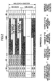
- Fig. 1 is a recording format of recording information in the first embodiment
- SYNC indicates a synchronizing signal designating the first position of a SYNC block
- SA denotes a sector address indicating a number assigned to a sector
- appended data is information added to main data to indicate, for example, a feature of the main data
- main data is primary record information
- C2 stands for a second error correction code (to be abbreviated as a C2 code herebelow) added to the appended and main data
- C1 indicates a first error correction code (to be abbreviated as a C1 code herebelow) added to the appended and main data.
- Main data inputted thereto in a time series is subdivided into 128-byte (indicated as 128B in Fig. 1) units and then 2-byte (2B) appended data is added to each 128-byte unit, thereby producing 128 rows (128 blocks in Fig. 1). Gathering one byte at an identical position of each row including 130 (128 + 2) bytes of data, there is created a 14-byte C2 code to resultantly configure a C2 correction block.
- the 14-byte C2 code is arranged in the direction denoted by an arrow 10. Resultantly, the obtained C2 codes constitute 14 130-byte rows (14 blocks in Fig. 1).
- each of 142 (128 + 14) 130-byte rows is an 8-byte C1 code so as to construct a C1 correction block (designated by an arrow 102).
- a C1 correction block designated by an arrow 102
- the sector contains 2048 (128 x 16) bytes of main data.
- Each sector of data to be recorded on a disk is assigned with a number (sector address) unique thereto. Namely, a 3-byte sector address is added to each C1 correction block together with a synchronizing signal SYNC so as to form a SYNC block.
- a correction block which makes it possible to conclusively achieve the C1 and C2 corrections in the unit of 128 x 128 bytes of main data.
- the data items are written on the media in a sequence beginning at the highest SYNC block and ending with the lowest SYNC block.
- data is sequentially written in each SYNC block in a direction beginning at the left-most position thereof.
- the desired data in the sector can be decoded and converted into output data at a high speed.
- the target sector can be readily decided and hence data of the sector can be outputted at a high speed.
- the data continuously inputted in a time series is only subdivided to form the C1 correction block with the sequence of data kept unchanged. Consequently, when the data is corrected in the reproducing stage according to the C1 code to output the corrected data in the processed sequence, the resultant data is outputted in a sequence identical to that of input data recorded on the disk.
- the C1 code error correction When compared with the error correction of data according to the C2 code, the C1 code error correction enables the output data to be produced at a higher speed, leading to an advantageous effect of facilitating implementation of such special reproducing operations as a variable-speed data reproduction and a reverse data reproduction.
- the appended data, C1 code, C2 code, sector address, and synchronizing signal are added to main data in this order.
- the operation sequence may be varied only if the relationships between the respective codes and signals shown in Fig. 1 are kept unchanged.
- the C1 code is added to the appended data, whereas the C1 code is not provided for the sector address.
- the same advantageous effect is attainable regardless of presence or absence of the C1 code for the appended data and sector address.
- the appended data is disposed on the left of the main data, the effect above can be obtained even when the appended data is arranged at an intermediate point or on the right thereof.
- the C1 code which is on the right of the main data in the first embodiment, may be positioned at a middle point or on the right of the main data.
- the C1 correction blocks each including the C2 code are disposed in the last 14 blocks of one correction block.
- the C1 blocks may be arranged at an intermediate position or before the other 128 C1 correction blocks.
- the numbers respectively of bytes, blocks, and sectors of Fig. 1 may also be appropriately altered to attain the same advantage.
- Fig. 2 shows the layout of the correction block of Fig. 1 corresponding to one sector.
- the contents respectively of SYNC, SA, C1, and appended data are the same as those of Fig. 1.
- C2 codes are also added thereto as in Fig. 1.
- Each transport (TS) packet shown in this diagram has a fixed length and includes data items such as video signals represented in the compressed form.
- the main data includes a transport packet.
- the appended data in one sector, namely, 16 blocks includes 32 bytes.
- the 12-byte area for six blocks is allocated as common appended data area and is not directly related to the input data.
- Ten remaining blocks namely, a 20-byte area is assigned as an area to store therein appended or main data according to the input data.
- the main data is recorded therein when the main data is in the configuration of the transport packet.
- the appended data is additionally recorded therein in other cases.
- the area in which the main data is recorded satisfies Expression (1) as shown in Fig. 2 and hence an integral multiple of transport packets can be exactly recorded in the area.
- the data can be efficiently written on the recording media irrespective of whether or not the main data is in the configuration of the transport packet.
- the common appended data area of Fig. 2 is used to record therein a code indicating whether or not the main data is in the form of the transport packet, the data reproduction can be appropriately carried out for disks in both of the data configurations above. This advantage is also obtained even when the data layout varies between the sectors of the disk. Even if the numeric values shown in the embodiment is changed, the same advantage is obtainable only if the condition of Expression (1) is satisfied.
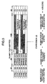
- Fig. 3 shows the data layout of the correction block of Fig. 1 corresponding to six SYNC blocks.
- SYNC, SA, C1, and appended data represent the same items as those of Fig. 1.
- C2 codes are assumed to be also added thereto as in Fig. 1.
- Each transport packet of Fig. 3 is configured in the same way as for that of Fig. 2.
- m a natural number; two in this case
- transport packets are written in the main data area for every n (a natural number; three in this case) SYNC blocks.
- Written in eight-byte remaining portion of the main data area is dummy data not having significance.
- the data can be efficiently written on the recording media regardless of whether or not the main data is in the configuration of the transport packet.
- the common appended data area of Fig. 2 is used to write therein a code indicating whether or not the main data is in the form of the transport packet, the data reproduction can be appropriately carried out irrespective of the data configuration.
- timing information may be recorded in place of the dummy data or may be recorded as a portion of the sector address or appended data.
- the numeric values of the third embodiment may be varied only if the condition of Expression (2) as shown in Fig. 3 is satisfied.
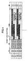
- Fig. 4 description will be given of a fourth embodiment Excepting S0 and S1, the constituent elements of Fig. 4 are the same as those of Fig. 3. Reference symbols S0 and S1 of Fig. 4 indicate synchronizing signals having mutually different patterns. Signals S0 and S1 are added to each SYNC block. The pattern of S0 appears for every n SYNC blocks. Consequently, such decoding operation as a data correction and the detection of the transport packet can be correctly achieved.
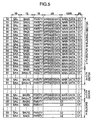
- Fig. 5 shows in detail the SYNC and SA fields of Fig. 1.
- the appended data, main data, C1 code, and C2 code are the same as those of Fig. 1.
- SAu, SAm, and SAl collectively denote a 3-byte sector address. Namely, SAu, SAm, and SAl respectively indicate an upper-most address, an intermediate address, and a lower-most address thereof.
- the sector address is written eight times for each sector.
- Fig. 5 shows data of sectors ranging from the n-th sector to the (n + 7)-th sector.
- the parenthesized value appended to SAl designates a sector address represented by SAu, SAm, and SAl.
- BA stands for a number assigned to a SYNC block in the correction block.
- the associated value in the parentheses thereof indicates by way of example a numeric value assigned to each two-block unit, namely, a one-block address is assigned to every two blocks.
- the sector address added to the SYNC block in which the C2 code is recorded may be assigned in an arbitrary manner if the sector address is other than any sector address assigned to the main data. In Fig. 5, a particular natural number k is assigned to each SYNC block including the C2 code.
- a code which makes it possible to discriminate the first SYNC block of the correction block or a synchronizing signal having a particular pattern unique to the first SYNC block.
- the parity code is related to a group of SAu and BA or a group including SAm and SAl.
- S0 and S1 are synchronizing signals indicating the first position of each SYNC block. These signals have mutually different patterns in which S0 denotes a recording cycle of the sector address.
- a SYNC block including S0 is considered to include SAu and BA and a SYNC block in which S1 is written is assumed to contain SAm and SAl.
- sector address information can be appropriately decided at a high speed without decoding the C1 code and hence the data access speed is increased.
- the sector address includes three bytes and the block address (BA) is of one byte and is written for every second blocks in this embodiment, the present invention is not restricted by these values.
- the precision of positional information of the block address is improved.
- the precision of sensing the sector address and precision of correcting data according to the C2 code can be improved.
- data successively inputted in a time series is only subdivided to form C1 blocks with the input sequence thereof kept unchanged.
- the order of recording the input data is retained in the data outputting operation. Thanks to this provision, in addition to the advantage that the sector address can be appropriately sensed at a high speed, the data can be outputted at a higher speed when compared with the case in which the C2 code is also used to correct the data. This leads to an advantageous effect of facilitating the special data reproduction such as a variable-speed data reproduction and a reverse data reproduction.
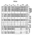
- FIG. 6 shows in detail the SYNC and SA fields of Fig. 1.
- the constituent elements other than S0, S1, SA, BA, and parity are the same as those of Fig. 5.
- SA denotes a sector address and is written 16 times for each sector.
- Fig. 6 shows data from the n-th sector to the (n + 7)-th sector in which the parenthesized value appended to SA designates a sector address.
- BA stands for a number assigned to a SYNC block in the correction block.
- the value in the parentheses of BA indicates by way of example a numeric value of a one-block address for each block.
- the sector address added to the SYNC block in which the C2 code is recorded may be assigned in an arbitrary manner if the sector address is other than any sector address of the main data.
- a particular natural number k is assigned to each SYNC block including the C2 code.
- the parity code is related to 3-byte SA and 1-byte BA.
- S0 and S1 are synchronizing signals indicating the first position of each SYNC block. These signals have mutually different patterns in which S0 denotes the first position of the correction block.
- information of sector addresses can be appropriately determined at a high speed without decoding the C1 code and therefore the data access speed is increased. Thanks to the synchronizing signals and block addresses, the first position of the correction block can be detected with high reliability.
- the sector address includes three bytes and the block address (BA) is of one byte in this embodiment, it is not restricted by these values.
- the first position of the correction block can be decided according to the types of synchronizing signals, the similar advantage is attainable even when the block address is missing.
- block addresses it is possible to detect the first position of the correction block, and the same advantage is obtained without discriminating the synchronizing signals S0 and S1 from each other.
- the precision of positional information indicated by the block address is improved.
- data successively inputted in a time series is only subdivided to construct C1 blocks with the input sequence thereof kept unchanged. Consequently, in the data reproduction, when the data is corrected according to the C1 code and then is outputted in the processing sequence, the input data recording order is retained in the data outputting operation. Thanks to this provision, in addition to the advantage that the sector address can be appropriately sensed at a high speed, the data can be outputted at a higher speed when compared with the case in which the C2 code is also used to correct the data. This leads to an advantageous effect of facilitating such special data reproduction as a variable speed data reproduction and a reverse data reproduction.
- Fig. 7 shows the format of data arrangement of one correction block employed in the recording method of the seventh embodiment. Since the difference between Fig. 7 and Fig. 1 resides only in the operation to add C1 and C2 codes to the data, description of the other constituent elements will be avoided.
- the C1 and C2 correction blocks include only data of one correction block as in Fig. 1, there is used another way of collecting the constituent data items. The data gathering method will be described. Collecting data with a delay of p (p: natural number other than 130 (bytes) which is the total of one row of appended and main data) from the appended and main data configured in the same fashion as for Fig. 1, there is configured a C2 correction block.
- n-th C2 correction block is indicated by arrow 701 in the diagram.
- the arrow is folded to be continuously drawn as indicated by arrow 703. Namely, the data collecting operation is continued along arrows 702 and 703 to resultantly obtain a C2 collection block.
- an 8-byte C1 code is added to each row thereof to construct a C1 correction block as a result.
- Added to each C1 block are a sector address and a synchronizing signal in a manner similar to that of Fig. 1, thereby forming one correction block.
- Data items are written on the recording media in the same way as for Fig. 1.
- data of an objective sector can be reproduced at a high speed equivalent to that developed for the data arrangement of Fig. 1.
- the code redundancy of the seventh embodiment can be lowered by the SYNC, SA, appended data, and C1 code of the SYNC block in which the C2 code is recorded.
- data successively inputted in a time series is only subdivided to construct C1 blocks with the input sequence thereof kept unchanged, when the data is corrected, in the data reproduction, according to the C1 code and is then outputted in the processing sequence, the recording order of the input data is retained in the data outputting operation.
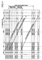
- Fig. 8 is a flowchart showing a method of reproducing data on a disk according to the eighth method and Fig. 11 shows by way of example the format of an oblique data interleaving procedure used in the method.
- reference numeral 802 indicates a C1 error correction process and numeral 803 denotes a step of detecting header information added to each block or each group of blocks.
- the header information is recorded as portion of, e.g., the appended data or sector address.
- the header information includes a code designating a method of interleaving the recorded signals.
- Numeral 804 indicates a step of examining the header information to decide that the interleaving type is an orthogonal block-complete type or an oblique block-incomplete type
- numeral 805 denotes an oblique block-incomplete de-interleaving process
- numeral 807 represents an orthogonal block-complete de-interleaving process
- numerals 806 and 808 each represent a C2 error correction step of correcting errors according to the C2 code added to the pertinent data.
- Numeral 809 indicates a processing step to decide the end of data reproduction.
- C2 codes are added to the data as shown in Fig. 1.
- FIG. 11 shows an example of the oblique block incomplete interleaving process.
- This diagram changes from Fig. 7 only in the arrangement of the C2 correction block.
- data is gathered with a delay of p (p: natural number other than 130 (bytes) which is the total of one row of appended and main data) from the appended and main data configured in the same fashion as for Fig. 7, thereby producing a C2 correction block.
- p natural number other than 130 (bytes) which is the total of one row of appended and main data
- a 14-byte C2 code is added to the block.
- the arrangement of Fig. 11 is different from Figs. 1 and 7 in that such correction blocks terminating respectively with the C1 and C2 blocks are missing.
- the C2 correction steps 806 and 808 the C2 corrections are respectively effected for the data of C2 blocks respectively gathered by the de-interleaving processes 805 and 807.
- the loop of C1 error correction and that of de-interleaving and C2 error correction are concurrently or sequentially performed.
- the C1 correction step 802 is basically common to both interleaving processes, when the block data varies in the number of bytes, there is achieved a change-over operation to transfer the control to an operation step associated thereto.
- the record format of Fig. 11 need not be necessarily used in the orthogonal block-complete interleaving operation as described in conjunction with the eighth embodiment. Namely, only the record format can be effectively employed as an independent element . Furthermore, the format can be efficiently adopted in the combination with each of the embodiments described in relation to Figs. 2 to 6. Namely, only the addition of correction codes of Fig. 11 is accomplished in Figs.
- Fig. 13 is different from Fig. 11 only in that the C1 code is included in the C2 correction block.
- the data reproduction method of the embodiment for either one of the interleaving methods, when the data is corrected according to the C1 code to be outputted without changing the sequence of data items, the input data order can be retained in the output operation.
- the sector address can be appropriately decided at a high speed, the data can be outputted at a higher speed as compared with the case using the C2 code also for the data correction.
- the oblique interleaving method of Fig. 13 may be partly modified such that the input data is arranged in a time series according to the arranging order of the lines of C2 correction blocks. Although the advantageous capability of data reproduction only with the C1 correction is lost in this case, the modified method is applicable also to the eighth embodiment. Moreover, when used in combination with each of the embodiments respectively related to Figs. 2 to 6, the above method leads to an advantage similar to that of the eighth embodiment, for example, in the sector detection as well as in the data recording efficiency when recording data in the transport packet configuration.
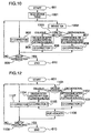
- Fig. 9 shows in a block diagram a data reproducing apparatus in the ninth embodiment.
- the orthogonal block-complete and oblique block-incomplete interleaving operations are assumed to be conducted according to the data formats of Figs. 1 and 11, respectively.
- Reference numerals 901 to 903 designate input process means, header sense means, and a random access memory, respectively.
- Numeral 904 indicates means for generating a write address for reproduction data
- numeral 905 represents means for creating read and write addresses for C1 error correction
- numeral 906 denotes switching means
- numeral 907 indicates means for generating read and write addresses for C2 error correction associated with orthogonal block-complete de-interleaving
- numeral 908 indicates means for generating read and write addresses for C2 error correction associated with oblique block-incomplete de-interleaving
- numeral 909 indicates error correction means for achieving C1 and C2 error corrections
- numeral 910 represents means for creating a read address of output data
- numeral 911 denotes output process means.
- the input process means 901 conducts decoding and synchronization sensing operations for signals inputted thereto and writes the obtained input data in the RAM 903. In this operation, a write address is created by the address generating means 904.
- the sense means 902 detects a header of the input data and selects the address creating means 907 or 908 according to information of the header.
- the address generating means 905 creates addresses respectively used to read data from the RAM 903 to the error correction means and to write data from the means 909 in the RAM 903.
- the address generated from the means 905 need not be subjected to a change-over operation according to the pertinent interleaving mode.
- Each of the means 907 and 908 controls the data reading or writing sequence such that the means 909 achieves the error correction in the C2 block unit shown in Fig. 1 or 11, thereby performing the pertinent de-interleaving operation.
- the change-over means 906 is responsive to a switching signal from the header sense means 902 to select the address from the means 907 or 908.
- data is read from the RAM 903 according to the read address from the means 911 regardless of the operation mode, namely, in the data sequence employed when the data is recorded on the disk. The obtained data is then fed to the output means 911 to be outputted therefrom in the sector unit.
- Fig. 10 is a flowchart showing a method of reproducing data on a disk in the tenth embodiment.
- Fig. 10 is different from Fig. 8 only in steps 1001 to 1003 associated with detection of the interleaving method and. hence only the processing of this portion will be described.
- Reference numeral 1001 indicates a sector table read process to read from a particular area of the disk a correspondence table including a correspondence between sector addresses and interleaving modes.
- Numeral 1002 denotes a step to detect a sector address
- numeral 1003 is a step to select an interleaving process according to the table obtained in step 1001 and the sector address detected in step 1002.
- the other processing steps are substantially the same as those of Fig. 8.
- Fig. 12 is a flowchart showing a method of recording data on a disk in accordance with the 11th embodiment.
- the orthogonal block-complete interleaving and oblique block-incomplete interleaving respectively of Figs. 1 and 11 by way of example.
- reference numeral 1101 indicates a step to select the orthogonal block-complete interleaving or oblique block-incomplete interleaving
- numeral 1104 is a step to conduct the oblique block-incomplete interleaving
- numeral 1102 denotes a step to accomplish the orthogonal block-complete interleaving
- each of numerals 1105 and 1103 represents a step to add the C2 code to the pertinent data
- numeral 1106 is a step to add a header to the data
- numeral 1107 indicates a step to add a C1 code to the data.
- step 1101 the oblique block-incomplete interleaving is selected when the record data includes, e.g., compressed video and audio signals; whereas, orthogonal block-complete interleaving is chosen when the data is, for example, data stored for computers or the like.
- a C2 block is configured as shown in Fig. 11 in step 1104.
- step 1105 a data correcting operation is conducted for the obtained data, thereby completing the oblique block-incomplete interleaving for the input data.
- a C2 block is created as shown in Fig.
- step 1106 a code indicating that the pertinent sector is associated with the oblique or orthogonal interleaving is added as the header.
- Step 1107 of adding C1 codes is basically common to any data. However, when the number of bytes varies between the C1 blocks in either interleaving modes, control is transferred to an appropriate process. Incidentally, the processing loops respectively of adding C1 and C2 codes are executed concurrently or sequentially. In step 1106, there is executed an operation as shown in Fig. 12 when the header includes SA and the C2 code is not added as shown in Figs. 1 and 11. However, when the header is recorded together with the C2 code as appended data, the process of step 1106 is executed immediately after step 1101.
- a disk data reproducing apparatus in which data of a target sector of the disk can be reproduced at a high speed and compressed video signals and the like on the disk can also be reproduced. Moreover, the objective data including only compressed video signals or the like can be recorded on the disk so that the recorded signals are reproduced by an apparatus of a simple configuration.
- Fig. 14 shows an identifier code and a sector address, the identifier code denoting that the input signal is in the transport packet configuration.
- the sector address of Figs. 5 and 6 including three bytes, i.e., 24 bits is expressed by 23 bits and the upper-most bit is assigned as the identifier code in Fig. 14.
- the input signal is in the transport packet form when the identifier code is set to, e.g., zero, and the input signal is in other forms when the code is, for example, one.
- the position of the sector address shown in Figs. 5 and 6 is used as that of the identifier code in the correction block.
- the data reproduction apparatus can recognize the recording format according to the identifier code and hence appropriately reproduces the data on the disk.
- the identifier code indicating whether or not the input signals are in the transport packet configuration is stored in a portion of the sector address area, it is also possible to store the identifier code in a portion of the block address field of Figs. 5 and 6 in a similar fashion.
- the data can be easily retrieved in the sector unit and the operation to reproduce data in the sector unit can be carried out at a high speed. Since the total of one-sector main data having a capacity expressed by a power of two and a portion of appended data added to the sector is equal to the data capacity of a plurality of transport packets, compressed video signals and user data for data application can be efficiently recorded on the disk while reducing the invalid unused areas in the recording areas of the disk. Furthermore, when the output data is produced only by achieving the C1 correction, the data can be outputted in a sequence equal to the data input sequence, which advantageously facilitates special data reproducing operations.
- the media on which data is recorded according to the present invention naturally includes optical, magnetic, opto-magnetic disks and the contour thereof is not limited to that of a disk. Moreover, the data need not be successively recorded thereon.
Landscapes
- Engineering & Computer Science (AREA)
- Signal Processing (AREA)
- Multimedia (AREA)
- Signal Processing For Digital Recording And Reproducing (AREA)
- Optical Recording Or Reproduction (AREA)
Claims (2)
- Support d'enregistrement d'informations, contenant :dans lequel un signal de synchronisation (S0) d'un bloc de synchronisation particulier d'un secteur qui contient ladite adresse la plus haute (SAu) du secteur est différent d'un signal de synchronisation (S1) de tous les blocs de synchronisation se trouvant dans le secteur qui n'incluent pas ladite adresse la plus haute (SAu) du secteur, un signal de synchronisation (S0) d'un bloc de synchronisation d'un secteur qui contient ladite adresse la plus haute (SAu) du secteur est le même qu'un signal de synchronisation (S0) d'un bloc de synchronisation d'un autre secteur qui inclut ladite adresse la plus haute (SAu) du secteur pour identifier ledit autre secteur, et la longueur de code des signaux de synchronisation (S0, S1) de tous les blocs de synchronisation est la même.une pluralité de blocs de synchronisation organisés pour former un secteur,une pluralité desdits secteurs organisée pour former un bloc de correction d'erreur,au moins un signal de synchronisation contenu dans chacun desdits blocs de synchronisation, etune adresse de secteur pour identifier un secteur, ladite adresse de secteur comportant une adresse la plus haute (SAu) qui est contenue au moins dans l'un desdits blocs de synchronisation dudit secteur,
- Dispositif de lecture pour lire un signal à partir d'un support d'enregistrement d'informations selon la revendication 1, ledit dispositif comportant :des moyens pour détecter l'adresse la plus haute d'un secteur, sur la base d'une différence entre le signal de synchronisation du bloc de synchronisation particulier qui contient ladite adresse la plus haute du secteur et les signaux de synchronisation de tous les autres blocs de synchronisation dudit secteur qui n'incluent pas ladite adresse la plus haute du secteur,des moyens pour détecter l'adresse de secteur pour identifier le secteur sur la base d'informations de l'adresse la plus haute détectée du secteur, etdes moyens pour identifier et délivrer en sortie des données requises conformément à l'adresse de secteur détectée.
Applications Claiming Priority (5)
| Application Number | Priority Date | Filing Date | Title |
|---|---|---|---|
| JP3646295 | 1995-02-24 | ||
| JP3646295 | 1995-02-24 | ||
| JP7045245A JP2882302B2 (ja) | 1995-02-24 | 1995-03-06 | 情報の記録方法及び再生方法 |
| JP4524595 | 1995-03-06 | ||
| EP96102364A EP0729151B1 (fr) | 1995-02-24 | 1996-02-16 | Méthode d'enregistrement d'informations, méthode de reproduction et appareil de reproduction |
Related Parent Applications (1)
| Application Number | Title | Priority Date | Filing Date |
|---|---|---|---|
| EP96102364A Division EP0729151B1 (fr) | 1995-02-24 | 1996-02-16 | Méthode d'enregistrement d'informations, méthode de reproduction et appareil de reproduction |
Publications (3)
| Publication Number | Publication Date |
|---|---|
| EP0999552A2 EP0999552A2 (fr) | 2000-05-10 |
| EP0999552A3 EP0999552A3 (fr) | 2000-05-17 |
| EP0999552B1 true EP0999552B1 (fr) | 2002-12-18 |
Family
ID=26375527
Family Applications (3)
| Application Number | Title | Priority Date | Filing Date |
|---|---|---|---|
| EP96102364A Expired - Lifetime EP0729151B1 (fr) | 1995-02-24 | 1996-02-16 | Méthode d'enregistrement d'informations, méthode de reproduction et appareil de reproduction |
| EP00102214A Expired - Lifetime EP0997903B1 (fr) | 1995-02-24 | 1996-02-16 | Procédé d'enregistrement d'informations et procédé de reproduction |
| EP00102213A Expired - Lifetime EP0999552B1 (fr) | 1995-02-24 | 1996-02-16 | Support d'enregistrement d'informations et appareil de reproduction |
Family Applications Before (2)
| Application Number | Title | Priority Date | Filing Date |
|---|---|---|---|
| EP96102364A Expired - Lifetime EP0729151B1 (fr) | 1995-02-24 | 1996-02-16 | Méthode d'enregistrement d'informations, méthode de reproduction et appareil de reproduction |
| EP00102214A Expired - Lifetime EP0997903B1 (fr) | 1995-02-24 | 1996-02-16 | Procédé d'enregistrement d'informations et procédé de reproduction |
Country Status (8)
| Country | Link |
|---|---|
| US (5) | US5768298A (fr) |
| EP (3) | EP0729151B1 (fr) |
| JP (1) | JP2882302B2 (fr) |
| KR (1) | KR100239236B1 (fr) |
| CN (3) | CN1065646C (fr) |
| DE (3) | DE69625524T2 (fr) |
| IN (1) | IN188992B (fr) |
| MY (2) | MY116447A (fr) |
Families Citing this family (47)
| Publication number | Priority date | Publication date | Assignee | Title |
|---|---|---|---|---|
| US5878010A (en) * | 1994-08-06 | 1999-03-02 | Hitachi, Ltd. | Method and apparatus for recording digital signal |
| JP2882302B2 (ja) * | 1995-02-24 | 1999-04-12 | 株式会社日立製作所 | 情報の記録方法及び再生方法 |
| US5978958A (en) * | 1995-04-03 | 1999-11-02 | Matsushita Electric Industrial Co., Ltd. | Data transmission system, data recording and reproducing apparatus and recording medium each having data structure of error correcting code |
| JP3430193B2 (ja) * | 1997-01-20 | 2003-07-28 | 株式会社日立製作所 | ディジタル信号再生装置及びディジタル信号再生方法 |
| JP3669103B2 (ja) * | 1997-03-14 | 2005-07-06 | 株式会社日立製作所 | 記憶装置および記憶装置サブシステム |
| US6279134B1 (en) * | 1998-03-02 | 2001-08-21 | Hitachi, Ltd. | Storage device and storage subsystem for efficiently writing error correcting code |
| DE19713286A1 (de) * | 1997-03-29 | 1998-10-01 | Thomson Brandt Gmbh | Gerät zur CD-Wiedergabe mit veränderbarer Geschwindigkeit oder Richtung |
| JPH1173737A (ja) * | 1997-08-29 | 1999-03-16 | Sony Corp | 記録装置及び方法、再生装置及び方法並びに記録媒体 |
| TW451188B (en) * | 1997-09-10 | 2001-08-21 | Sony Corp | Information recording method and apparatus and information recording medium |
| JPH1185580A (ja) * | 1997-09-11 | 1999-03-30 | Matsushita Electric Ind Co Ltd | ファイル管理システム及びファイル管理方法 |
| JPH11110920A (ja) * | 1997-09-30 | 1999-04-23 | Toshiba Corp | 誤り訂正符号化方法及び装置、誤り訂正復号化方法及び装置、並びにデータ記録・再生装置、並びに記憶媒体 |
| JPH11297000A (ja) * | 1998-04-03 | 1999-10-29 | Toshiba Corp | データ生成方法及びデータ生成装置 |
| DE69832791T2 (de) * | 1998-07-09 | 2006-08-03 | Hewlett-Packard Development Co., L.P., Houston | Verbessertes Datenschreiben auf Datenspeichermedium |
| US6421805B1 (en) * | 1998-11-16 | 2002-07-16 | Exabyte Corporation | Rogue packet detection and correction method for data storage device |
| JP3502559B2 (ja) * | 1999-02-05 | 2004-03-02 | 松下電器産業株式会社 | 消失訂正方法、及び消失訂正回路 |
| JP3529665B2 (ja) * | 1999-04-16 | 2004-05-24 | パイオニア株式会社 | 情報変換方法及び情報変換装置並びに情報再生装置 |
| US6754680B1 (en) * | 1999-05-20 | 2004-06-22 | Matsushita Electric Industrial Co., Ltd. | Data control equipment, method to control data and recording medium to record data control procedure |
| JP3827897B2 (ja) | 1999-11-22 | 2006-09-27 | シャープ株式会社 | 光ディスクの記録方法、光ディスク記録装置、光ディスク再生装置 |
| JP4304802B2 (ja) * | 1999-12-17 | 2009-07-29 | ソニー株式会社 | ダビング装置 |
| US7088911B2 (en) * | 2000-04-26 | 2006-08-08 | Sony Corporation | Recording apparatus and method, playback apparatus and method, and recording medium therefor |
| US8656246B2 (en) * | 2001-04-16 | 2014-02-18 | Qualcomm Incorporated | Method and an apparatus for use of codes in multicast transmission |
| KR100425294B1 (ko) * | 2001-04-20 | 2004-03-30 | 삼성전자주식회사 | 광 정보저장매체, 및 그 데이터 기록장치 |
| JP2002329367A (ja) * | 2001-04-27 | 2002-11-15 | Sony Corp | データ記録方法および装置、データ再生方法および装置、並びにデータ記録媒体 |
| US6978414B2 (en) * | 2001-07-17 | 2005-12-20 | Hewlett-Packard Development Company, L.P. | Method and apparatus for protecting against errors occurring in data storage device buffers |
| JP3993035B2 (ja) * | 2001-07-19 | 2007-10-17 | 松下電器産業株式会社 | データ記録方法、記録媒体、および再生装置 |
| US6877127B2 (en) * | 2001-07-31 | 2005-04-05 | Hewlett-Packard Development Company, L.P. | Quality control in data transfer and storage apparatus |
| US6958873B2 (en) * | 2001-07-31 | 2005-10-25 | Hewlett-Packard Development Company, L.P. | Data rewrite control in data transfer and storage apparatus |
| US6883122B2 (en) * | 2001-07-31 | 2005-04-19 | Hewlett-Packard Development Company, L.P. | Write pass error detection |
| US6792568B2 (en) | 2001-07-31 | 2004-09-14 | Hewlett Packard Development Co. Lp | Data transfer and storage device and method |
| US7042667B2 (en) * | 2001-07-31 | 2006-05-09 | Hewlett-Packard Development Company, L.P. | Data storage |
| US20030044166A1 (en) * | 2001-08-31 | 2003-03-06 | Stmicroelectronics, Inc. | System for multiplexing video data streams in a digital video recorder and method of operating the same |
| JP3559540B2 (ja) | 2001-09-07 | 2004-09-02 | 株式会社東芝 | 多目的情報記憶媒体及び記憶方法及び再生方法及び再生装置 |
| KR100833880B1 (ko) * | 2001-11-06 | 2008-06-02 | 엘지전자 주식회사 | 유자 형상의 스캔을 이용한 광디스크 데이터기록장치/방법 및 재생장치/방법 |
| KR100811628B1 (ko) * | 2001-11-06 | 2008-03-11 | 엘지전자 주식회사 | 워블 어드레스가 기록된 기록 가능한 광디스크와, 그에따른 워블 어드레스검출장치 및 방법 |
| JP3688628B2 (ja) * | 2001-11-09 | 2005-08-31 | 株式会社東芝 | 信号処理方法及び装置、信号再生方法及び装置、記録媒体 |
| JP2004213704A (ja) * | 2002-12-26 | 2004-07-29 | Toshiba Corp | 情報記録再生方法と情報記録再生装置及び情報記録媒体 |
| US7379505B2 (en) * | 2003-02-13 | 2008-05-27 | Broadcom Corporation | Method and apparatus for performing trellis coded modulation of signals for transmission on a TDMA channel of a cable network |
| JP3850433B2 (ja) * | 2003-06-02 | 2006-11-29 | 松下電器産業株式会社 | インタリーブデータに対する誤り訂正方法および装置 |
| KR20050020650A (ko) * | 2003-08-18 | 2005-03-04 | 소니 가부시키가이샤 | 데이터 레코딩/재생 디바이스, 데이터 레코딩/재생 방법,프로그램, 및 레코딩 매체 |
| EP1683364A1 (fr) * | 2003-11-13 | 2006-07-26 | Matsushita Electric Industrial Co., Ltd. | Paquetisation de donnees codees a debit binaire variable basee sur un controle de debit |
| US7430158B1 (en) | 2004-12-13 | 2008-09-30 | Chris Tanner | Music player with adjustable pitch controller |
| US20090028030A1 (en) * | 2006-02-10 | 2009-01-29 | Pioneer Corporation | Apparatus and Method for Driving Optical Disc and Optical Disc Recording Apparatus |
| EP1887446A1 (fr) * | 2006-08-02 | 2008-02-13 | Siemens Aktiengesellschaft | Procédé destiné à la transmission asynchrone sérielle de données dans un dispositif de contrôle, de commande et de régulation d'une installation technique industrielle d'un bâtiment |
| CN101312349B (zh) * | 2007-05-26 | 2010-08-25 | 华为技术有限公司 | 信息块编码及同步检测的方法和装置 |
| JP5194747B2 (ja) * | 2007-12-04 | 2013-05-08 | 富士ゼロックス株式会社 | データ伝送装置、データ送信装置、データ受信装置及びデータ伝送システム |
| US8145975B2 (en) * | 2008-02-28 | 2012-03-27 | Ip Video Communications Corporation | Universal packet loss recovery system for delivery of real-time streaming multimedia content over packet-switched networks |
| JPWO2010113481A1 (ja) * | 2009-03-31 | 2012-10-04 | シャープ株式会社 | ドライブ装置、コンテンツ記録再生装置、データ書き込み方法、プログラムおよび記録媒体 |
Family Cites Families (40)
| Publication number | Priority date | Publication date | Assignee | Title |
|---|---|---|---|---|
| US4949326A (en) * | 1986-12-10 | 1990-08-14 | Matsushita Electric Industrial Co., Ltd. | Optical information recording and reproducing system using optical disks having an error correction function |
| JPS58148551A (ja) * | 1982-02-27 | 1983-09-03 | Sony Corp | デイジタル信号伝送方法 |
| US4564945A (en) * | 1983-06-20 | 1986-01-14 | Reference Technology, Inc. | Error-correction code for digital data on video disc |
| JPS6069917A (ja) * | 1983-09-26 | 1985-04-20 | Pioneer Electronic Corp | デ−タ伝送方式 |
| CA1258134A (fr) * | 1985-04-13 | 1989-08-01 | Yoichiro Sako | Methode de correction d'erreurs |
| US4656532A (en) * | 1985-07-29 | 1987-04-07 | International Business Machines Corporation | Sector identification method for hard sectored hard files |
| AU594995B2 (en) * | 1986-01-24 | 1990-03-22 | Sony Corporation | Data transmission method suitable for a disc |
| JP2590813B2 (ja) * | 1986-02-18 | 1997-03-12 | ソニー株式会社 | データの記録方法 |
| JPS62234426A (ja) * | 1986-04-04 | 1987-10-14 | Sony Corp | エラ−訂正方法 |
| US4907215A (en) * | 1986-08-27 | 1990-03-06 | Sony Corporation | Integral optical recording of product code in data areas |
| JPS63179471A (ja) * | 1987-01-20 | 1988-07-23 | Sanyo Electric Co Ltd | デ−タ記録方法及びデ−タ記録/再生方法 |
| JPS63251968A (ja) * | 1987-04-08 | 1988-10-19 | Pioneer Electronic Corp | デイスク記録方式 |
| JPH01235073A (ja) * | 1988-03-14 | 1989-09-20 | Sony Corp | データ種別検出装置 |
| JP2829963B2 (ja) * | 1988-05-16 | 1998-12-02 | ソニー株式会社 | ディジタルデータ記録/再生装置 |
| JPH02263365A (ja) * | 1989-04-03 | 1990-10-26 | Alps Electric Co Ltd | 磁気ディスク駆動装置のエラー補正方法 |
| US5333126A (en) * | 1990-01-03 | 1994-07-26 | Hitachi, Ltd. | Information recording method and optical disk apparatus using same |
| JP2638248B2 (ja) * | 1990-03-15 | 1997-08-06 | 松下電器産業株式会社 | 光学的情報媒体および再生装置および記録装置および再生方法および記録方法 |
| JP3109087B2 (ja) * | 1990-08-24 | 2000-11-13 | ソニー株式会社 | 符号化装置及び復号化装置 |
| US5293388A (en) * | 1990-11-13 | 1994-03-08 | Hewlett-Packard Company | Compression/decompress with ECC data flow architecture |
| JPH05135367A (ja) * | 1991-11-08 | 1993-06-01 | Sony Corp | 光デイスクの記録方式及び再生方式 |
| US5365530A (en) * | 1992-05-12 | 1994-11-15 | Mitsubishi Denki Kabushiki Kaisha | Error-correction encoding and decoding system |
| JP3428039B2 (ja) * | 1992-06-30 | 2003-07-22 | ソニー株式会社 | 同期信号検出器、同期信号検出方法及び復号化装置 |
| JPH06236632A (ja) * | 1993-02-09 | 1994-08-23 | Matsushita Electric Ind Co Ltd | 光ディスクおよび光ディスク再生装置 |
| JP3440952B2 (ja) * | 1993-02-24 | 2003-08-25 | ソニー株式会社 | データ記録方法及びデータ再生方法 |
| JP3427410B2 (ja) * | 1993-02-24 | 2003-07-14 | ソニー株式会社 | 光ディスク記録装置および光ディスク再生装置 |
| US5640378A (en) * | 1993-02-25 | 1997-06-17 | Sony Corporation | Disc recording apparatus for recording data in units of a full cluster |
| JP2905368B2 (ja) * | 1993-08-10 | 1999-06-14 | 富士通株式会社 | 誤り検出・訂正方法 |
| US5623467A (en) * | 1993-09-27 | 1997-04-22 | Matsushita Electric Industrial Co., Ltd. | Data recording apparatus for recording data in sector units |
| KR100319990B1 (ko) * | 1993-09-29 | 2002-04-22 | 이데이 노부유끼 | 데이타재생방법및데이타재생장치 |
| FR2712760B1 (fr) * | 1993-11-19 | 1996-01-26 | France Telecom | Procédé pour transmettre des bits d'information en appliquant des codes en blocs concaténés. |
| JP2786810B2 (ja) * | 1994-03-16 | 1998-08-13 | 株式会社東芝 | 光ディスクおよびその信号記録装置ならびに信号再生装置 |
| JP2920065B2 (ja) * | 1994-03-16 | 1999-07-19 | 株式会社東芝 | データ記録方法、記録装置、再生装置及び再生方法 |
| JP2856072B2 (ja) * | 1994-06-27 | 1999-02-10 | 株式会社日立製作所 | 情報記録方法、情報再生方法および情報再生装置 |
| JP3282385B2 (ja) * | 1994-07-12 | 2002-05-13 | 株式会社日立製作所 | ディジタル情報記録方法及び記録装置 |
| JP3373690B2 (ja) * | 1994-09-07 | 2003-02-04 | 株式会社東芝 | ディスク状記録媒体及びディスク装置 |
| JPH0896522A (ja) * | 1994-09-20 | 1996-04-12 | Sony Corp | データエンコーダ |
| JPH08161752A (ja) * | 1994-12-06 | 1996-06-21 | Sony Corp | データ記録装置およびデータ再生装置 |
| JPH08221906A (ja) * | 1995-02-15 | 1996-08-30 | Toshiba Corp | データ形成方法、データ再生方法、データ形成装置、データ再生装置および記憶媒体 |
| JP2882302B2 (ja) * | 1995-02-24 | 1999-04-12 | 株式会社日立製作所 | 情報の記録方法及び再生方法 |
| JPH08279252A (ja) * | 1995-03-31 | 1996-10-22 | Fujitsu Ltd | デコード装置及び記憶装置 |
-
1995
- 1995-03-06 JP JP7045245A patent/JP2882302B2/ja not_active Expired - Lifetime
-
1996
- 1996-02-16 EP EP96102364A patent/EP0729151B1/fr not_active Expired - Lifetime
- 1996-02-16 EP EP00102214A patent/EP0997903B1/fr not_active Expired - Lifetime
- 1996-02-16 EP EP00102213A patent/EP0999552B1/fr not_active Expired - Lifetime
- 1996-02-16 DE DE69625524T patent/DE69625524T2/de not_active Expired - Lifetime
- 1996-02-16 DE DE69625720T patent/DE69625720T2/de not_active Expired - Lifetime
- 1996-02-16 DE DE69627741T patent/DE69627741T2/de not_active Expired - Lifetime
- 1996-02-16 US US08/602,708 patent/US5768298A/en not_active Expired - Lifetime
- 1996-02-19 IN IN297CA1996 patent/IN188992B/en unknown
- 1996-02-21 KR KR1019960004072A patent/KR100239236B1/ko not_active Expired - Lifetime
- 1996-02-24 MY MYPI96000673A patent/MY116447A/en unknown
- 1996-02-24 CN CN96105518A patent/CN1065646C/zh not_active Expired - Lifetime
- 1996-02-24 MY MYPI20004928A patent/MY125074A/en unknown
- 1996-02-24 CN CNB031016014A patent/CN1282183C/zh not_active Expired - Lifetime
-
1997
- 1997-10-24 US US08/957,741 patent/US5974581A/en not_active Expired - Lifetime
-
1998
- 1998-01-26 US US09/013,198 patent/US5983387A/en not_active Expired - Lifetime
-
1999
- 1999-03-23 CN CNB991043952A patent/CN1134780C/zh not_active Expired - Lifetime
- 1999-08-02 US US09/365,816 patent/US6076184A/en not_active Expired - Lifetime
-
2000
- 2000-02-28 US US09/514,279 patent/US6314542B1/en not_active Expired - Lifetime
Also Published As
| Publication number | Publication date |
|---|---|
| CN1145514A (zh) | 1997-03-19 |
| JP2882302B2 (ja) | 1999-04-12 |
| CN1516158A (zh) | 2004-07-28 |
| DE69627741T2 (de) | 2004-02-26 |
| EP0999552A3 (fr) | 2000-05-17 |
| DE69625524T2 (de) | 2003-09-25 |
| US5768298A (en) | 1998-06-16 |
| DE69625720D1 (de) | 2003-02-13 |
| EP0729151B1 (fr) | 2003-05-02 |
| US5974581A (en) | 1999-10-26 |
| EP0997903B1 (fr) | 2003-01-08 |
| EP0999552A2 (fr) | 2000-05-10 |
| CN1134780C (zh) | 2004-01-14 |
| MY116447A (en) | 2004-01-31 |
| KR100239236B1 (ko) | 2000-01-15 |
| JPH08293161A (ja) | 1996-11-05 |
| CN1065646C (zh) | 2001-05-09 |
| DE69625720T2 (de) | 2003-11-06 |
| DE69627741D1 (de) | 2003-06-05 |
| US6314542B1 (en) | 2001-11-06 |
| EP0997903A3 (fr) | 2000-05-17 |
| KR960032451A (ko) | 1996-09-17 |
| US5983387A (en) | 1999-11-09 |
| IN188992B (fr) | 2002-12-07 |
| CN1282183C (zh) | 2006-10-25 |
| DE69625524D1 (de) | 2003-01-30 |
| CN1232261A (zh) | 1999-10-20 |
| EP0729151A3 (fr) | 1997-04-09 |
| EP0997903A2 (fr) | 2000-05-03 |
| US6076184A (en) | 2000-06-13 |
| MY125074A (en) | 2006-07-31 |
| EP0729151A2 (fr) | 1996-08-28 |
| HK1023443A1 (en) | 2000-09-08 |
Similar Documents
| Publication | Publication Date | Title |
|---|---|---|
| EP0999552B1 (fr) | Support d'enregistrement d'informations et appareil de reproduction | |
| US7805062B2 (en) | Transmitting and recording method, reproducing method, and reproducing apparatus of information and its recording medium | |
| JP3610608B2 (ja) | ディスク記録方法、および、ディスク記録装置 | |
| CN100530403C (zh) | 信息再生设备 | |
| JP3381628B2 (ja) | 情報の記録方法及び再生方法 | |
| KR100239238B1 (ko) | 정보기록매체 및 재생장치 | |
| HK1023443B (en) | Information recording method and reproducing method | |
| JP3257291B2 (ja) | ディジタル信号記録方法及び装置 | |
| JPH1097767A (ja) | ディジタル情報記録方式及び記録装置 | |
| JPH10116476A (ja) | ディジタル情報記録方式及び記録装置 | |
| JPH1021656A (ja) | 誤り判定装置 | |
| JPH04286775A (ja) | 磁気記録再生装置 |
Legal Events
| Date | Code | Title | Description |
|---|---|---|---|
| PUAI | Public reference made under article 153(3) epc to a published international application that has entered the european phase |
Free format text: ORIGINAL CODE: 0009012 |
|
| PUAL | Search report despatched |
Free format text: ORIGINAL CODE: 0009013 |
|
| 17P | Request for examination filed |
Effective date: 20000210 |
|
| AC | Divisional application: reference to earlier application |
Ref document number: 729151 Country of ref document: EP |
|
| AK | Designated contracting states |
Kind code of ref document: A2 Designated state(s): DE FR GB |
|
| AK | Designated contracting states |
Kind code of ref document: A3 Designated state(s): DE FR GB |
|
| RIN1 | Information on inventor provided before grant (corrected) |
Inventor name: TAKEUCHI, TOSHIFUMI Inventor name: HIRABAYASHI, MASAYUKI Inventor name: NAKAMURA, MASAFUMI, GADENPOTO II-701 Inventor name: NAGAI, YUTAKA |
|
| 17Q | First examination report despatched |
Effective date: 20001013 |
|
| AKX | Designation fees paid |
Free format text: DE FR GB |
|
| GRAG | Despatch of communication of intention to grant |
Free format text: ORIGINAL CODE: EPIDOS AGRA |
|
| GRAG | Despatch of communication of intention to grant |
Free format text: ORIGINAL CODE: EPIDOS AGRA |
|
| GRAH | Despatch of communication of intention to grant a patent |
Free format text: ORIGINAL CODE: EPIDOS IGRA |
|
| GRAH | Despatch of communication of intention to grant a patent |
Free format text: ORIGINAL CODE: EPIDOS IGRA |
|
| GRAA | (expected) grant |
Free format text: ORIGINAL CODE: 0009210 |
|
| AC | Divisional application: reference to earlier application |
Ref document number: 729151 Country of ref document: EP |
|
| AK | Designated contracting states |
Kind code of ref document: B1 Designated state(s): DE FR GB |
|
| REG | Reference to a national code |
Ref country code: GB Ref legal event code: FG4D |
|
| REF | Corresponds to: |
Kind code of ref document: P Ref document number: 69625524 Country of ref document: DE Date of ref document: 20030130 |
|
| ET | Fr: translation filed | ||
| PLBE | No opposition filed within time limit |
Free format text: ORIGINAL CODE: 0009261 |
|
| STAA | Information on the status of an ep patent application or granted ep patent |
Free format text: STATUS: NO OPPOSITION FILED WITHIN TIME LIMIT |
|
| 26N | No opposition filed |
Effective date: 20030919 |
|
| REG | Reference to a national code |
Ref country code: DE Ref legal event code: R081 Ref document number: 69625524 Country of ref document: DE Owner name: HITACHI CONSUMER ELECTRONICS CO., LTD., JP Free format text: FORMER OWNER: HITACHI, LTD., TOKYO, JP Effective date: 20130207 Ref country code: DE Ref legal event code: R082 Ref document number: 69625524 Country of ref document: DE Representative=s name: BARDEHLE PAGENBERG PARTNERSCHAFT PATENTANWAELT, DE Effective date: 20130207 Ref country code: DE Ref legal event code: R082 Ref document number: 69625524 Country of ref document: DE Representative=s name: BARDEHLE PAGENBERG PARTNERSCHAFT MBB PATENTANW, DE Effective date: 20130207 |
|
| REG | Reference to a national code |
Ref country code: GB Ref legal event code: 732E Free format text: REGISTERED BETWEEN 20130404 AND 20130410 |
|
| REG | Reference to a national code |
Ref country code: FR Ref legal event code: TP Owner name: HITACHI CONSUMER ELECTRONICS CO., LTD., JP Effective date: 20130409 |
|
| REG | Reference to a national code |
Ref country code: FR Ref legal event code: PLFP Year of fee payment: 20 |
|
| PGFP | Annual fee paid to national office [announced via postgrant information from national office to epo] |
Ref country code: DE Payment date: 20150210 Year of fee payment: 20 |
|
| PGFP | Annual fee paid to national office [announced via postgrant information from national office to epo] |
Ref country code: FR Payment date: 20150210 Year of fee payment: 20 Ref country code: GB Payment date: 20150211 Year of fee payment: 20 |
|
| REG | Reference to a national code |
Ref country code: DE Ref legal event code: R071 Ref document number: 69625524 Country of ref document: DE |
|
| REG | Reference to a national code |
Ref country code: GB Ref legal event code: PE20 Expiry date: 20160215 |
|
| PG25 | Lapsed in a contracting state [announced via postgrant information from national office to epo] |
Ref country code: GB Free format text: LAPSE BECAUSE OF EXPIRATION OF PROTECTION Effective date: 20160215 |