EP0986676B1 - Auffangwanne - Google Patents
Auffangwanne Download PDFInfo
- Publication number
- EP0986676B1 EP0986676B1 EP98929424A EP98929424A EP0986676B1 EP 0986676 B1 EP0986676 B1 EP 0986676B1 EP 98929424 A EP98929424 A EP 98929424A EP 98929424 A EP98929424 A EP 98929424A EP 0986676 B1 EP0986676 B1 EP 0986676B1
- Authority
- EP
- European Patent Office
- Prior art keywords
- collecting vessel
- bricks
- rim
- sealing
- vessel according
- Prior art date
- Legal status (The legal status is an assumption and is not a legal conclusion. Google has not performed a legal analysis and makes no representation as to the accuracy of the status listed.)
- Expired - Lifetime
Links
- 238000007789 sealing Methods 0.000 claims abstract description 50
- 239000007788 liquid Substances 0.000 claims abstract description 14
- 231100001261 hazardous Toxicity 0.000 claims abstract description 7
- 238000007599 discharging Methods 0.000 claims abstract 2
- 230000007717 exclusion Effects 0.000 claims description 20
- 238000013461 design Methods 0.000 claims description 9
- 239000003566 sealing material Substances 0.000 claims description 8
- 239000011888 foil Substances 0.000 claims description 6
- 239000000523 sample Substances 0.000 claims description 3
- 238000003860 storage Methods 0.000 claims description 3
- 238000003466 welding Methods 0.000 claims description 3
- 239000011248 coating agent Substances 0.000 claims description 2
- 238000000576 coating method Methods 0.000 claims description 2
- 150000001875 compounds Chemical class 0.000 claims description 2
- 239000011449 brick Substances 0.000 claims 16
- 230000002093 peripheral effect Effects 0.000 claims 1
- 238000009424 underpinning Methods 0.000 claims 1
- 230000004888 barrier function Effects 0.000 abstract description 4
- 238000000465 moulding Methods 0.000 description 45
- 239000000565 sealant Substances 0.000 description 24
- 239000004575 stone Substances 0.000 description 24
- 239000006260 foam Substances 0.000 description 18
- 229920001021 polysulfide Polymers 0.000 description 12
- 239000005077 polysulfide Substances 0.000 description 12
- 150000008117 polysulfides Polymers 0.000 description 12
- 230000006378 damage Effects 0.000 description 9
- 230000015572 biosynthetic process Effects 0.000 description 8
- 239000003673 groundwater Substances 0.000 description 7
- 239000004576 sand Substances 0.000 description 7
- 101150006573 PAN1 gene Proteins 0.000 description 6
- 239000000853 adhesive Substances 0.000 description 6
- 230000001070 adhesive effect Effects 0.000 description 6
- 238000009434 installation Methods 0.000 description 6
- 239000000463 material Substances 0.000 description 6
- 230000007774 longterm Effects 0.000 description 5
- 238000004519 manufacturing process Methods 0.000 description 5
- 230000000903 blocking effect Effects 0.000 description 4
- 239000000945 filler Substances 0.000 description 4
- 239000004033 plastic Substances 0.000 description 4
- 238000004026 adhesive bonding Methods 0.000 description 3
- KGNDCEVUMONOKF-UGPLYTSKSA-N benzyl n-[(2r)-1-[(2s,4r)-2-[[(2s)-6-amino-1-(1,3-benzoxazol-2-yl)-1,1-dihydroxyhexan-2-yl]carbamoyl]-4-[(4-methylphenyl)methoxy]pyrrolidin-1-yl]-1-oxo-4-phenylbutan-2-yl]carbamate Chemical compound C1=CC(C)=CC=C1CO[C@H]1CN(C(=O)[C@@H](CCC=2C=CC=CC=2)NC(=O)OCC=2C=CC=CC=2)[C@H](C(=O)N[C@@H](CCCCN)C(O)(O)C=2OC3=CC=CC=C3N=2)C1 KGNDCEVUMONOKF-UGPLYTSKSA-N 0.000 description 3
- 229940125833 compound 23 Drugs 0.000 description 3
- 238000006073 displacement reaction Methods 0.000 description 3
- 239000004744 fabric Substances 0.000 description 3
- 230000008859 change Effects 0.000 description 2
- 239000003344 environmental pollutant Substances 0.000 description 2
- 239000000835 fiber Substances 0.000 description 2
- 231100000719 pollutant Toxicity 0.000 description 2
- 239000004587 polysulfide sealant Substances 0.000 description 2
- 238000003825 pressing Methods 0.000 description 2
- 230000008439 repair process Effects 0.000 description 2
- 238000012549 training Methods 0.000 description 2
- 206010023230 Joint stiffness Diseases 0.000 description 1
- 238000010521 absorption reaction Methods 0.000 description 1
- 239000011149 active material Substances 0.000 description 1
- 239000002318 adhesion promoter Substances 0.000 description 1
- 230000015556 catabolic process Effects 0.000 description 1
- 238000006243 chemical reaction Methods 0.000 description 1
- 239000002131 composite material Substances 0.000 description 1
- 238000010276 construction Methods 0.000 description 1
- 238000011109 contamination Methods 0.000 description 1
- 238000005336 cracking Methods 0.000 description 1
- 230000007423 decrease Effects 0.000 description 1
- 238000006731 degradation reaction Methods 0.000 description 1
- 238000001514 detection method Methods 0.000 description 1
- 238000011161 development Methods 0.000 description 1
- 208000018459 dissociative disease Diseases 0.000 description 1
- 230000000694 effects Effects 0.000 description 1
- 238000005429 filling process Methods 0.000 description 1
- 239000004746 geotextile Substances 0.000 description 1
- 239000000383 hazardous chemical Substances 0.000 description 1
- 230000003993 interaction Effects 0.000 description 1
- 239000012528 membrane Substances 0.000 description 1
- 239000002480 mineral oil Substances 0.000 description 1
- 235000010446 mineral oil Nutrition 0.000 description 1
- 230000035515 penetration Effects 0.000 description 1
- 239000002985 plastic film Substances 0.000 description 1
- 230000001681 protective effect Effects 0.000 description 1
- 230000002787 reinforcement Effects 0.000 description 1
- 238000007711 solidification Methods 0.000 description 1
- 230000008023 solidification Effects 0.000 description 1
- 238000012360 testing method Methods 0.000 description 1
Images


Classifications
-
- E—FIXED CONSTRUCTIONS
- E02—HYDRAULIC ENGINEERING; FOUNDATIONS; SOIL SHIFTING
- E02D—FOUNDATIONS; EXCAVATIONS; EMBANKMENTS; UNDERGROUND OR UNDERWATER STRUCTURES
- E02D31/00—Protective arrangements for foundations or foundation structures; Ground foundation measures for protecting the soil or the subsoil water, e.g. preventing or counteracting oil pollution
Definitions
- the invention relates to a drip pan, in particular for receiving of environmentally hazardous liquids, according to the generic term of claim 1; see DE-A-43 36 570.
- Known drip pans are used to hold environmentally hazardous Liquids are provided as fuse bases, the one cast on-site base plate and adjoining this on the edge Have side walls.
- the drip pan is lined with foil sheets, the installation of industrial plants, storage containers, Transformer systems or the like can be damaged and the accessibility of such sumps is largely restricted.
- the invention is concerned with the problem of a drip pan create whose bottom and side walls with little technical Effort for long-term tightness even when it can be driven on Ensure the drip pan, which also after a leak has occurred without any interim contamination of the underbody can be repaired with little effort is.
- the drip pan according to the invention is a composite unit trained, the wall contours bottom and edge Have concrete moldings as individual components.
- This Shaped bodies form vertically and horizontally in the installed position Grooves as respective grooves, such that a sealant provided therein as a barrier zone for liquids is effective and the molded body cast from concrete integral part of an overall fluid-tight support structure are.
- On the floor moldings can be an environmentally hazardous Container containing liquid or the Trough floor is passable overall, so that for example a tanker or the like containing mineral oil into the sump can drive in. Even in these harsh operating conditions damage to the exclusion zone is avoided with long-term stability and unintentionally escaping liquid remains in the Drip pan. Over both the bottom area and the edge area exclusion zones of the tub body are intrusion the liquid in the area of the underbody too of an accident reliably prevented. In addition, in the In the area of the restricted zones so that occurring leaks are located and the Damaged area can be repaired without endangering the underbody can.
- the concrete moldings are in an appropriate design with each provided with cast geomembranes during manufacture, that protrude into the receiving groove on the edge and here are connected fluid-tight via a weld or adhesive seam.
- a sealing compound introduced into the receiving groove For example, a polysulfide adhesive, a Security of the exclusion zone as a whole still improving groove filling can be achieved.
- the arranged in passable areas of the receptacle Bottom and edge moldings are in their joint-side grooves thanks to a multi-layer filling structure secured against loads from driving and braking forces.
- a closure part provided in the groove base in the form a plug becomes a pressing in of bottom material, for example sand, avoided in the lower joint area, thus a displacement of the filling and Sealant even with high dynamic loads Molded floor prevents and protection for the top Sealant barrier zone is therefore also under rough operating conditions, for example in the area of a loading station with high vehicle loads, guaranteed long-term.
- the sealant barrier zones are expedient arranged that groundwater pressing groundwater is shielded is.
- this support and sealing structure can the drip pan in the area below the bottom molded body with a sealing film that is essentially parallel to the floor be provided as an additional exclusion zone.
- the film sealant in the area of the L-shaped edge shaped bodies are, for example assigned to the floor sealing film via an adhesive connection that the drip pan from a parallel fuse pan is undermined.
- This fuse base will be the highest Meets requirements even against stagnant groundwater, because this is derived in the area of a drainage below the bucket becomes.
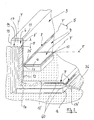
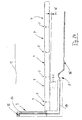
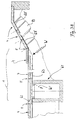
- Fig. 1 is a portion of a total designated 1 Catch pan shown to accommodate environmentally hazardous Liquids are provided and in doing so a recessed floor area 2, for example for industrial plants, Storage containers, transformer systems, loading stations or the like an uncontrolled penetration of pollutants into the Floor area 2, for example in the event of an accident, a leak or the like, is prevented.
- a recessed floor area 2 for example for industrial plants, Storage containers, transformer systems, loading stations or the like an uncontrolled penetration of pollutants into the Floor area 2, for example in the event of an accident, a leak or the like, is prevented.
- the drip pan 1 is made in the inventive design built on the bottom and edge concrete moldings, where in respective joint areas F between the edge molding 3 and bottom molded body 4 provided individual components at least a sealing zone 8, 8 'forming a blocking zone 5, 6, 7 are arranged.
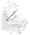
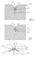
- FIG. 2 shows an enlarged detail representation of edge and base moldings 3 and 4 whose formation with recesses 10, 11 or inside projections 12, which in the case of adjacent laying the molded body has a common receiving groove for the sealant 8, 8 'limit.
- FIG. 2 clarifies this when viewed together 17 shows the formation of the respective exclusion zones 5 and 7 with sealing parts cast into the molded bodies 3, 4 8 'in the form of film material 14, 14' in the edge protrudes the respective joint area or the receiving groove.
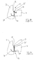
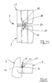
- Fig. 3 is the L-shaped edge molding 4 in an individual representation illustrates, this along its vertical and Horizontal leg 15, 16 with a one-piece continuous Sealing part in the form of the sealing film 14 with the front projecting portion 14 'is provided.
- the edge shaped bodies have 3 different embodiments the vertical exclusion zone 6, which is in the direction of the joint area F vertically in the direction of the leg 15 and horizontally in the direction of the leg 16 of the edge molding 3 extends.
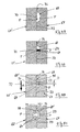
- the edge molding 3 in the region of the mutually facing transverse sides 17, 18 with a Groove / tongue profiling 19 (Fig. 2, Fig. 3) provided by which a precisely fitting toothing of the molded body is possible in this way (Fig. 4 to 6) that for repair purposes individual the edge molding 3 also released from the connection position and afterwards again connected to each other or to the bottom moldings 4 can be.
- this is in the receiving groove protruding sealing film 14 in the edge stones 3 over the end Barb 21 fixed and in the area of the restricted zone 6 provided with a seam 22 produced by welding or gluing.
- the sealing film has 14 multiple barbs 21 'on and in the embodiment 6 is a pourable as an additional sealant Sealant 23 introduced into the receiving groove and spaced via a cord 24 made of foam to the seam 22.
- Sealant 23 introduced into the receiving groove and spaced via a cord 24 made of foam to the seam 22.
- a sealant Pour polysulfide in the longitudinal direction of the entire receiving groove, so that the blocking zone 6 is double-secured with the seam 22 and the sealing compound 23, which also extends along of the horizontal leg 16 up to its end face with the Foil area 14 can extend.
- the two sealants 23 and 23 ' In the area of the molding 12 (Fig. 2) intersect the two sealants 23 and 23 ', so that the exclusion zone 5 is formed.
- FIGS. 7 to 9 show a change in the area of the tongue and groove profile 19, with an additional Receiving chamber 25 for the respective seam 22 of the sealing films 14 is provided and the sealant 23 with the Cord 24 directly adjoins the groove profile 19 '.
- Fig. 10 is in the respective edge molding 3 in the longitudinal direction extending perforated plastic sheet or the like.
- a sealing film 14 "cast in Fig. 11 is the sealing film 14" as a fabric part having holding fibers 27 is formed and in 12 is the sealing film 14 "'over a connector 28 on a cast structural reinforcement 29 stably hooked.
- FIG. 12 Similar to the embodiment according to FIG. 12, one in FIG continuous, in particular wavy fabric web 30 made of oriented fibers or nonwoven material, which is glued to the receiving groove with the sealing film 14 '' '.
- an additional connecting means in the form of an Plastic part cast in or used during assembly 31 provided.
- the tongue and groove profile a receiving chamber 25 'encapsulated with polysulfide seal 32 on the bottom side with a foam layer 33 (FIG. 16) is filled in such a way that the polysulfide layer 32 is elastically supported and has only one flank 26, 26 'existing liability of the reception chamber are cracks in the Sealant for slight displacements of the molded edge 3 avoided.
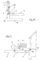
- FIG. 17 to 19 show the connection position the bottom molding 4 in the area of the inside molding 11 on the L-shaped edge shaped bodies 3, the horizontal legs 16 the edge molding 3 the bottom molding 4 in reach under a distance A. It is like a synopsis with Fig. 1 becomes clear in the horizontal section of the sump 1 a double-layer securing through the interaction the exclusion zones 5, 6 and 7 reached.
- the lower exclusion zone 7 is of the catch pan 1 over the entire surface below the bottom molded body 4 and with the Sealing parts 14 of the edge molding 3 connected sealing film 36 formed.
- the sealing film 14 is in the restricted area 6 shown in two layers
- Fig. 18 is the sealing film 14 only in the area of the vertical leg 15 up to the exclusion zone 5 provided
- Fig. 19 shows a double-layer version with a short extension to restricted area 5.
- FIG. 20 and 21 show the enlarged representations expedient embodiments in the area of the exclusion zone 5 between the bottom moldings 4 and the inside molding 12 on the L-shaped shaped edge body 3.
- the web-shaped Plastic parts 37, 38 as a sealant in the area a seam 22 'connected, and this is as an additional Fuse the polysulfide sealant 40 (Fig. 21) introduced.
- Fig. 22 the blocking zone 7 'is at the front end of the horizontal leg 16 provided with the formation 12 'in the area both the sealing film 14 ', 14 are connected as well Sealant 23 are introduced so that the sump 1 according to 23 is formed.
- Fig. 23 to 28 show further embodiments the sump 1.
- Fig. 23 is a complete one Cross section with enlarged horizontal leg 16 L-stones 3 and on the foot side of this Bottom moldings 4 shown (Fig. 22)
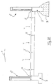
- Fig. 24 shows the Collecting trough 1 with an inclined N shaped body 4 similar to Fig. 1, with the sump on one side is open and passable.
- the edge molding 3 ′′ have respective support feet S, S ′, which are underneath, for example, a concrete layer B.
- the shaped concrete bodies 4 delimit to a bearing surface 43 provided as a basement wall a sealing film 44 screwed on the one hand and to each assigned bottom molded body 4 is welded on the other hand (Fig. 26).
- FIG. 28 shows a drivable drip pan 1 ', in which on the one hand an edge molding 3' in a sealing connection stands with a driving surface 45 and starting from this the bottom molding 4 forming the collecting trough 1 'up to an otherwise provided limit with the L-shaped Edge shaped bodies 3 are laid with a slope N '.
- the inner one Driving surface 45 'on the top of the floor molding 4 has Sealant largely lowered in the grooves 8, 8 ', so that in this passable version Damage to exclusion zone 5 from vehicle tires avoided is.
- 29 to 32 are similar to the joint designs in the area the L-shaped body 3 the connection options the cast sealing foils 14 are shown in the base moldings 4, the design features with the embodiment 4 to 6 are comparable and thus in these respective exclusion zones 5, 7 'essentially the same, long-term stable Sealing conditions have been reached.
- the seals described above are in the grooves between edge molding 3 and bottom molding 4 in Area of the sealing means 8, 8 'or the sealing foils 14, 14' see above designed that if one of the blocking zones 5 is damaged, 6, 7, 7 '(by means of the measuring probes 42, 42' on the liquid detection is detectable), the moldings concerned in each case 3, 4 can be replaced and then the severed sealing areas or restricted areas without any problems are recoverable.
- Shaped bodies 3, 4 is sealing film 14, particularly in areas with high pressure loads, e.g. at the edge of the drip pan 1, with an extended reserve part R at the upper end provided (Fig. 24) so that after inserting an adjacent new molding this part R a renewed welding or gluing.
- the tongue / groove profiling 19 can in an advantageous embodiment with a low tooth depth Z (Fig.
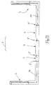
- 33 to 36 are the laying conditions during manufacture shown the bottom of the tub, the respective bottom molded body 4 on a base layer 46 of ballast or lean concrete and a formation layer 47, for example made of sand, are hung up. This is followed by solidification in this installation position by means of a vibrator 48, also in the receiving grooves fillers 55 (FIG. 35) are solidified (Arrow R).
- the opposite Molded base 4 mutually in respective areas 52 and 53 of the short side and the bottom side with a Adhesion-preventing material, such as a wax, coated.
- a Adhesion-preventing material such as a wax
- the filling sand introduced is 55 (Fig. 33) by means of an adhesive entry (filling member 60, Fig. 34) at least in regions to a plug 54, 54 '(Fig. 35, Fig. 36) solidified on the coating areas 52 and 53 is not liable, so that a balance of horizontal and / or vertical movements is possible.
- the Floor moldings 4 are rectangular paving stones only two adjoining side surfaces with the wax layer provided so that in the laying position coated and uncoated Areas in the receiving groove face each other.
- this measure is a postponement of the Sand 55 'from the formation layer 47 and the sand 55 from the Prevents grooves and the top polysulfide layer 23 remains undamaged under pressure loads.
- the embodiment shown in FIG. 36 shows an adhesive entry (FIG. 34), which extends into the area of the formation layer 47 took place, so that with an enlarged plug 54 ' Edge areas of the stones 3 are detected and their tilting movement is prevented.
- the sand 55 present in this area can do not drain and into the area of the polysulfide insert 23 parts of the formation layer cannot be postponed.
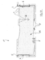
- FIG. 37 shows a drip pan 1 ", the complete with a filler 56 up into the top Edge area of the L-shaped stones 3 '(left side of the figure) filled is similar, so that a passability in this area 28 is achieved.
- the representation ends the laying plane of the shaped base body 4 below the upper edge of the edge molding 3.
- the out Filling layer formed from special biologically active materials 56 provided as a conversion space for pollutants is. This can be used, for example, as a transshipment point trained floor moldings 4 unwanted leaking liquids derived via the grooves and in the filling layer 56 biodegradable. Through this biological Degradation decreases the concentration of environmentally hazardous Fabrics in a direction H to the tub floor, so that the Tub body 1 'with simple exclusion zones 5 and 6 the security requirements justice.
- the in different designs and installation positions as a sealing membrane used film 14, 14 ', 14' ', 14' '' is at least in some areas on the molded body in the connecting position upper side with a roughened adhesive structure 60 (Fig. 2) provided for the introduced into the joint area Polysulfide 23 enables improved adhesion.
- the roughened Structure 60 ' can be of one during film manufacture generated profile or a subsequently incorporated Structural change must be formed.
- the polysulfide grouting is between the shaped bodies of the sump 1 Long-term stable and slight shifts can be made without cracking in the area of the film 14 and / or the polysulfide 23 be balanced.
- Fig. 38 the bucket 1 is in an inclined position located floor moldings 4 provided, being in the horizontal A drainage shaft 61 in the area of the drain pan integrated for groundwater on the ground.
- the top with a cover 62 fluid-tight to the receiving space of the tub closed collecting container 61 has one adjacent Molded base 4 at least in some areas Drainage plate 63, by means of which only the arrow W groundwater shown at W 'introduced into the collecting shaft 61 can be.
- This is damage to the floor moldings 4 or the seals in the area of joint F due to groundwater reliably avoided.
- the bottom moldings 4 still in the inclined area of a protective film 63 ' Undermined, for example, from a on the concrete layer B glued geotextile and the groundwater to the drainage plate 63 leads.
- Fig. 39 is the bottom shaped body designed as a hexagon 64 4 shown in a plan view, with its respective Side flanks provided plastic parts 65, in particular made of foam.
- the one about Part area of the side surface extending foam parts 65 can be glued after the production of the molded body 3 or 4 be (Fig. 41) or already in the manufacture of the corresponding Concrete molded body 64 via a retaining shoulder 66 in the molded body can be integrated (Fig. 42 to 45). In the laying position each cover the foam parts 65 Part of Fugue F.
- the foam parts 65th each extend over a portion of the side surface and with this juxtaposition of the hexagon stones 64 a closure the receiving groove or the joint F in the manner of that already shown in FIG. 2 shown cord 24 is formed.
- the plastic parts 65 are advantageous on the shaped bodies 4 (or 3, Fig. 44, 45) determined that a complex assembly when laying the Components on the construction site is unnecessary.
- the filling sand 55 can be introduced and then the pourable sealant 23, for example in the form of polysulfide, for the final closure of the Fug F can be applied.
- FIG. 44 Joint structure F in the area of a vertical joint of the L-shaped Shaped edge body 3 shown (similar to Fig. 8), the sealant 23 is introduced in the form of filler.
- the 45 shows the foam body 65 in Connection with a formation of the joint shape similar to FIG. 21, wherein the shaped body 3 and at the bottom of the tub body 1 4 adjoin each other.
- Fig. 46 are shaped bottom blocks 67 formed as rectangular stones 4 shown, which are also in the area of a joint F.
- the cross-sectional representations according to FIGS. 47 to 51 show (according to a section line A-A in FIG. 46) an embodiment of sealing chambers 68 on the side surfaces of the stones 67, with at least one foam part 69 in the chambers 68 is glued in.
- 48 shows the one hand provided sealing chamber 68 on the stone 67 and the assigned stone 67 'is provided with a marking edge 70, when filling the liquid sealant 23 (Fig. 49) allows easy control of the fill level.
- a primer effective as an adhesion promoter and the sealing compound 23 are in the longitudinal direction of the joints F, respectively Filling openings 71 (Fig. 46) recessed so that similar to Embodiment according to FIG. 34 via a filling member 60 of the entry of the liquid sealant is possible.
- these chambers 68 is the multi-layer joint seal against external damage protected.
- the sealing material 23 is made of two and four foam parts 69, 69 'surround, the sealing material 23 only with respective in the sealing chamber 68 or perpendicular to the side surface of the opposite stone 67 ' extending surface areas P is glued.
- the sealing material 23 is only deformed so that a Damage to the joint tightness is avoided and in the area the mutually supported side surfaces of the shaped bodies 67 and 67 'local overloads from the individual stones and the Sealing system can be included without damage.
- Over a wedge-shaped Gaps 77 (FIGS. 47, 51) can form contours of the stones these are positioned in an inclined installation position, whereby overloading of the edges in the area of the gap 77 is avoided are.
- the sealing compound 23 has in the joint F or the chamber 68 a cross-section, which by means of the foam parts 69, 69 ' formed with a medium material contour of small thickness D. is. This makes it elastically stretchable after the filling process Sealant 23 for optimal load absorption in this way dimensioned that an unwanted tearing of the sealing material 23rd avoided by the stones (in area P) and in the above Pressure loads (arrow 72) zone D according to Art a predetermined deformation line in the longitudinal direction of the joint is effective.
- the respective lower foam parts 69 dimensioned so that an unwanted leakage of the liquid Sealant is prevented when filling.
- a subsequent tightness check in the area of the joints F is in sections between neighboring areas with little effort Filling openings 71 possible, this with a plug part be closed and then by means of a joint F suction cup positioned on the stones (not shown) a vacuum test can be carried out so that environmental hazards safely avoided in the area of the sump 1 become.
Landscapes
- Engineering & Computer Science (AREA)
- Life Sciences & Earth Sciences (AREA)
- Environmental & Geological Engineering (AREA)
- Hydrology & Water Resources (AREA)
- General Life Sciences & Earth Sciences (AREA)
- Mining & Mineral Resources (AREA)
- Paleontology (AREA)
- Civil Engineering (AREA)
- General Engineering & Computer Science (AREA)
- Structural Engineering (AREA)
- Sewage (AREA)
- Grinding-Machine Dressing And Accessory Apparatuses (AREA)
- Rear-View Mirror Devices That Are Mounted On The Exterior Of The Vehicle (AREA)
- Glass Compositions (AREA)
- Filling Or Discharging Of Gas Storage Vessels (AREA)
- Cleaning In General (AREA)
- Foundations (AREA)
- Cultivation Receptacles Or Flower-Pots, Or Pots For Seedlings (AREA)
- Catching Or Destruction (AREA)
- Details Of Rigid Or Semi-Rigid Containers (AREA)
- Road Paving Structures (AREA)
- Electrical Discharge Machining, Electrochemical Machining, And Combined Machining (AREA)
- Revetment (AREA)
- Iron Core Of Rotating Electric Machines (AREA)
Priority Applications (1)
| Application Number | Priority Date | Filing Date | Title |
|---|---|---|---|
| SI9830232T SI0986676T1 (en) | 1997-06-07 | 1998-06-05 | Collecting vessel |
Applications Claiming Priority (3)
| Application Number | Priority Date | Filing Date | Title |
|---|---|---|---|
| DE29709938U DE29709938U1 (de) | 1997-06-07 | 1997-06-07 | Auffangwanne |
| DE29709938U | 1997-06-07 | ||
| PCT/EP1998/003385 WO1998055701A1 (de) | 1997-06-07 | 1998-06-05 | Auffangwanne |
Publications (2)
| Publication Number | Publication Date |
|---|---|
| EP0986676A1 EP0986676A1 (de) | 2000-03-22 |
| EP0986676B1 true EP0986676B1 (de) | 2002-07-31 |
Family
ID=8041304
Family Applications (1)
| Application Number | Title | Priority Date | Filing Date |
|---|---|---|---|
| EP98929424A Expired - Lifetime EP0986676B1 (de) | 1997-06-07 | 1998-06-05 | Auffangwanne |
Country Status (10)
| Country | Link |
|---|---|
| EP (1) | EP0986676B1 (pl) |
| AT (1) | ATE221600T1 (pl) |
| AU (1) | AU7918698A (pl) |
| CZ (1) | CZ297444B6 (pl) |
| DE (2) | DE29709938U1 (pl) |
| ES (1) | ES2179510T3 (pl) |
| HU (1) | HU226440B1 (pl) |
| PL (1) | PL196702B1 (pl) |
| SI (1) | SI0986676T1 (pl) |
| WO (1) | WO1998055701A1 (pl) |
Cited By (1)
| Publication number | Priority date | Publication date | Assignee | Title |
|---|---|---|---|---|
| DE202010003935U1 (de) | 2010-03-19 | 2011-08-01 | Karl Kortmann | Auffangwanne zur Aufnahme von umweltgefährdenden Produkten |
Families Citing this family (2)
| Publication number | Priority date | Publication date | Assignee | Title |
|---|---|---|---|---|
| DE102005053911A1 (de) * | 2005-08-08 | 2007-02-15 | S. Müller Patent Entwicklungs und Verpachtungs GmbH & Co. KG | Verfahren zum Nachrüsten eines Leckageschutzes für stationäre Tanks oder Behälter |
| DE102015004388A1 (de) | 2015-04-10 | 2016-10-13 | Dieter Swoboda | Sicherungseinrichtung für Untersuchungs- und Bohrplätze in umweltgefährdeten Bereichen |
Family Cites Families (17)
| Publication number | Priority date | Publication date | Assignee | Title |
|---|---|---|---|---|
| US698050A (en) * | 1902-01-03 | 1902-04-22 | Sterling T Playford | Sectional tank. |
| DE1038261B (de) * | 1957-02-20 | 1958-09-04 | Chem Fab Gruenau Ag | Verfahren und Geraet zum Verbinden geformter Bauteile aus einem hydraulisch abbindenden Baustoff mit Fugenbaendern |
| DE1818866U (de) * | 1960-02-20 | 1960-09-29 | Leopold Mueller | Stahlbeton-schutzwanne fuer heizol- und treibstofflagerbehaelter. |
| DE1821016U (de) * | 1960-09-03 | 1960-11-03 | Leopold Mueller | Schutzwanne fuer heizoel- und treibstoff-lagerbehaelter. |
| FR2173368A5 (pl) * | 1972-02-21 | 1973-10-05 | Nicephor Andre | |
| NL7505062A (nl) * | 1975-04-29 | 1976-11-02 | Stamicarbon | Betonnen reservoir samengesteld uit geprefabri- ceerde elementen. |
| EP0411389A1 (de) * | 1989-08-02 | 1991-02-06 | Hans-Jürgen Klatt | Flüssigkeitsdichte Auffangwanne |
| EP0445341B1 (de) * | 1990-03-09 | 1992-11-19 | Stelcon Aktiengesellschaft | Flüssigkeitsdichter Industriefussbodenbelag |
| DE9003844U1 (de) * | 1990-04-03 | 1990-06-13 | Schaup, Reiner | Elemente und deren Verbindungen zur Erstellung nahtloser Auffangwannen |
| DE9005435U1 (de) * | 1990-05-12 | 1990-07-26 | Becker, Annette, 5300 Bonn | Tragwanne für Lastkraftwagen zum Auffangen von flüssigen Stoffen |
| DE9109114U1 (de) * | 1991-02-06 | 1991-11-07 | Stelcon Ag, 4300 Essen | Erweiterbares Lager für VBF-Produkte gemäß WHG |
| DE4122413C2 (de) * | 1991-06-11 | 1997-02-13 | Heitkamp Gmbh E | Verfahren und Vorrichtung zur Herstellung eines Auffangraumes |
| DE9108276U1 (de) * | 1991-07-04 | 1991-10-17 | Strätner, Heinz, 4300 Essen | Auffangplatte für Tankfahrzeugbefüllstationen |
| DE9117082U1 (de) * | 1991-11-06 | 1995-10-26 | Dipl.-Ing. Helmut Hemmerlein GmbH & Co. Bau KG, 91077 Neunkirchen | Betonwanne |
| DE4434503A1 (de) * | 1993-09-27 | 1995-03-30 | Schuette Reiner | Flüssigkeitsdichte Fahrbahn |
| DE4336570A1 (de) * | 1993-10-27 | 1995-05-04 | Walter Ludwig Behaelter Stahl | Wannen- oder beckenförmiger Auffangraum für in Ladebehältern gelagerte wassergefährdende Flüssigkeiten |
| DE29621187U1 (de) * | 1996-11-19 | 1997-02-06 | Lingen, Paul, 47669 Wachtendonk | Mehrschichtige Bodenfläche mit integriertem Schutz für Boden und Wasser |
-
1997
- 1997-06-07 DE DE29709938U patent/DE29709938U1/de not_active Expired - Lifetime
-
1998
- 1998-06-05 PL PL337325A patent/PL196702B1/pl not_active IP Right Cessation
- 1998-06-05 SI SI9830232T patent/SI0986676T1/xx unknown
- 1998-06-05 EP EP98929424A patent/EP0986676B1/de not_active Expired - Lifetime
- 1998-06-05 CZ CZ0439699A patent/CZ297444B6/cs not_active IP Right Cessation
- 1998-06-05 HU HU0002947A patent/HU226440B1/hu not_active IP Right Cessation
- 1998-06-05 AU AU79186/98A patent/AU7918698A/en not_active Abandoned
- 1998-06-05 DE DE59805017T patent/DE59805017D1/de not_active Expired - Lifetime
- 1998-06-05 AT AT98929424T patent/ATE221600T1/de active
- 1998-06-05 ES ES98929424T patent/ES2179510T3/es not_active Expired - Lifetime
- 1998-06-05 WO PCT/EP1998/003385 patent/WO1998055701A1/de not_active Ceased
Cited By (1)
| Publication number | Priority date | Publication date | Assignee | Title |
|---|---|---|---|---|
| DE202010003935U1 (de) | 2010-03-19 | 2011-08-01 | Karl Kortmann | Auffangwanne zur Aufnahme von umweltgefährdenden Produkten |
Also Published As
| Publication number | Publication date |
|---|---|
| DE29709938U1 (de) | 1998-10-08 |
| AU7918698A (en) | 1998-12-21 |
| DE59805017D1 (de) | 2002-09-05 |
| HU226440B1 (en) | 2008-12-29 |
| EP0986676A1 (de) | 2000-03-22 |
| PL337325A1 (en) | 2000-08-14 |
| ES2179510T3 (es) | 2003-01-16 |
| ATE221600T1 (de) | 2002-08-15 |
| WO1998055701A1 (de) | 1998-12-10 |
| HUP0002947A3 (en) | 2002-01-28 |
| CZ297444B6 (cs) | 2006-12-13 |
| PL196702B1 (pl) | 2008-01-31 |
| HUP0002947A2 (hu) | 2001-01-29 |
| CZ9904396A3 (cs) | 2001-04-11 |
| SI0986676T1 (en) | 2002-12-31 |
Similar Documents
| Publication | Publication Date | Title |
|---|---|---|
| EP0986676B1 (de) | Auffangwanne | |
| WO2008009483A1 (de) | Erdtank | |
| JPH08218410A (ja) | 流体貯蔵タンクの基礎補修工法 | |
| EP0358857B1 (de) | Dränschacht | |
| DE102012203818B4 (de) | Bodeneinsatz für Schachtbauwerke | |
| DE3809963C2 (pl) | ||
| DE69514878T2 (de) | Lagertank und Verfahren zur Überwachung von Lecks in Tankböden | |
| EP0326892B1 (de) | Stehender zylindrischer Behälter aus Stahlbeton, insbesondere zur Lagerung von Flüssigkeiten | |
| EP1252394B1 (de) | Bauteilanordnung zur erstellung eines fundamentes | |
| DE4015349C2 (pl) | ||
| AT228717B (de) | Schutzwanne | |
| DE4434503A1 (de) | Flüssigkeitsdichte Fahrbahn | |
| DE2939007A1 (de) | Betankungsanlage | |
| DE1181391B (de) | Schutzwanne fuer einen zylindrischen liegenden Fluessigkeitstank | |
| DE29705704U1 (de) | Aufbau einer Fahrbahndecke mit Flächendichtung | |
| WO2023227476A1 (de) | Rinnenelement zum entwässern | |
| CN109680727A (zh) | 一种危险品货物堆场工程的防渗结构体系及构筑方法 | |
| AT387344B (de) | Abfall-deponie | |
| DD144683A1 (de) | Arbeitsoeffnung,insbesondere rohrdurchfuehrung in der wandung eines betontanks | |
| DE202008008498U1 (de) | Doppelwandige Innenauskleidung für Flüssigkeitsbehälter, insbesondere aus Beton | |
| EP0467050B1 (de) | Auffangraum für bei einem Störfall freiwerdende umweltgefährdende Flüssigkeiten | |
| EP0863258A2 (de) | Aufbau einer Fahrbahndecke mit Flächendichtung | |
| CH403644A (de) | Schutzeinrichtung für einen zylindrischen, liegenden Flüssigkeitstank | |
| DE2337468A1 (de) | Lagertank mit auffangtasse | |
| DE9005435U1 (de) | Tragwanne für Lastkraftwagen zum Auffangen von flüssigen Stoffen |
Legal Events
| Date | Code | Title | Description |
|---|---|---|---|
| PUAI | Public reference made under article 153(3) epc to a published international application that has entered the european phase |
Free format text: ORIGINAL CODE: 0009012 |
|
| 17P | Request for examination filed |
Effective date: 19991130 |
|
| AK | Designated contracting states |
Kind code of ref document: A1 Designated state(s): AT BE CH DE DK ES FI FR GB GR IT LI NL SE |
|
| RAX | Requested extension states of the european patent have changed |
Free format text: SI PAYMENT 19991130 |
|
| GRAG | Despatch of communication of intention to grant |
Free format text: ORIGINAL CODE: EPIDOS AGRA |
|
| 17Q | First examination report despatched |
Effective date: 20011004 |
|
| GRAG | Despatch of communication of intention to grant |
Free format text: ORIGINAL CODE: EPIDOS AGRA |
|
| GRAH | Despatch of communication of intention to grant a patent |
Free format text: ORIGINAL CODE: EPIDOS IGRA |
|
| GRAH | Despatch of communication of intention to grant a patent |
Free format text: ORIGINAL CODE: EPIDOS IGRA |
|
| GRAA | (expected) grant |
Free format text: ORIGINAL CODE: 0009210 |
|
| AK | Designated contracting states |
Kind code of ref document: B1 Designated state(s): AT BE CH DE DK ES FI FR GB GR IT LI NL SE |
|
| AX | Request for extension of the european patent |
Free format text: SI PAYMENT 19991130 |
|
| PG25 | Lapsed in a contracting state [announced via postgrant information from national office to epo] |
Ref country code: GR Free format text: LAPSE BECAUSE OF FAILURE TO SUBMIT A TRANSLATION OF THE DESCRIPTION OR TO PAY THE FEE WITHIN THE PRESCRIBED TIME-LIMIT Effective date: 20020731 Ref country code: FI Free format text: LAPSE BECAUSE OF FAILURE TO SUBMIT A TRANSLATION OF THE DESCRIPTION OR TO PAY THE FEE WITHIN THE PRESCRIBED TIME-LIMIT Effective date: 20020731 |
|
| REF | Corresponds to: |
Ref document number: 221600 Country of ref document: AT Date of ref document: 20020815 Kind code of ref document: T |
|
| REG | Reference to a national code |
Ref country code: GB Ref legal event code: FG4D Free format text: NOT ENGLISH Ref country code: CH Ref legal event code: EP |
|
| REG | Reference to a national code |
Ref country code: CH Ref legal event code: NV Representative=s name: PATENTANWAELTE FELDMANN & PARTNER AG |
|
| REF | Corresponds to: |
Ref document number: 59805017 Country of ref document: DE Date of ref document: 20020905 |
|
| GBT | Gb: translation of ep patent filed (gb section 77(6)(a)/1977) |
Effective date: 20020829 |
|
| PG25 | Lapsed in a contracting state [announced via postgrant information from national office to epo] |
Ref country code: DK Free format text: LAPSE BECAUSE OF FAILURE TO SUBMIT A TRANSLATION OF THE DESCRIPTION OR TO PAY THE FEE WITHIN THE PRESCRIBED TIME-LIMIT Effective date: 20021031 |
|
| ET | Fr: translation filed | ||
| REG | Reference to a national code |
Ref country code: ES Ref legal event code: FG2A Ref document number: 2179510 Country of ref document: ES Kind code of ref document: T3 |
|
| PLBE | No opposition filed within time limit |
Free format text: ORIGINAL CODE: 0009261 |
|
| STAA | Information on the status of an ep patent application or granted ep patent |
Free format text: STATUS: NO OPPOSITION FILED WITHIN TIME LIMIT |
|
| 26N | No opposition filed |
Effective date: 20030506 |
|
| REG | Reference to a national code |
Ref country code: SI Ref legal event code: IF |
|
| REG | Reference to a national code |
Ref country code: CH Ref legal event code: PFA Owner name: KORTMANN, KARL Free format text: KORTMANN, KARL#AM WERKSHORN 21#48465 SCHUETTORF (DE) -TRANSFER TO- KORTMANN, KARL#AM WERKSHORN 21#48465 SCHUETTORF (DE) |
|
| PGFP | Annual fee paid to national office [announced via postgrant information from national office to epo] |
Ref country code: ES Payment date: 20120622 Year of fee payment: 15 |
|
| PGFP | Annual fee paid to national office [announced via postgrant information from national office to epo] |
Ref country code: AT Payment date: 20120626 Year of fee payment: 15 |
|
| PGFP | Annual fee paid to national office [announced via postgrant information from national office to epo] |
Ref country code: GB Payment date: 20130617 Year of fee payment: 16 Ref country code: SE Payment date: 20130625 Year of fee payment: 16 |
|
| PGFP | Annual fee paid to national office [announced via postgrant information from national office to epo] |
Ref country code: IT Payment date: 20130611 Year of fee payment: 16 |
|
| PGFP | Annual fee paid to national office [announced via postgrant information from national office to epo] |
Ref country code: BE Payment date: 20130621 Year of fee payment: 16 |
|
| PGFP | Annual fee paid to national office [announced via postgrant information from national office to epo] |
Ref country code: NL Payment date: 20130627 Year of fee payment: 16 Ref country code: CH Payment date: 20130924 Year of fee payment: 16 |
|
| PGFP | Annual fee paid to national office [announced via postgrant information from national office to epo] |
Ref country code: FR Payment date: 20130716 Year of fee payment: 16 |
|
| PGFP | Annual fee paid to national office [announced via postgrant information from national office to epo] |
Ref country code: DE Payment date: 20140602 Year of fee payment: 17 |
|
| REG | Reference to a national code |
Ref country code: NL Ref legal event code: V1 Effective date: 20150101 |
|
| PG25 | Lapsed in a contracting state [announced via postgrant information from national office to epo] |
Ref country code: SE Free format text: LAPSE BECAUSE OF NON-PAYMENT OF DUE FEES Effective date: 20140606 |
|
| REG | Reference to a national code |
Ref country code: CH Ref legal event code: PL |
|
| REG | Reference to a national code |
Ref country code: SE Ref legal event code: EUG |
|
| REG | Reference to a national code |
Ref country code: AT Ref legal event code: MM01 Ref document number: 221600 Country of ref document: AT Kind code of ref document: T Effective date: 20140605 |
|
| GBPC | Gb: european patent ceased through non-payment of renewal fee |
Effective date: 20140605 |
|
| REG | Reference to a national code |
Ref country code: FR Ref legal event code: ST Effective date: 20150227 |
|
| PG25 | Lapsed in a contracting state [announced via postgrant information from national office to epo] |
Ref country code: NL Free format text: LAPSE BECAUSE OF NON-PAYMENT OF DUE FEES Effective date: 20150101 |
|
| REG | Reference to a national code |
Ref country code: SI Ref legal event code: KO00 Effective date: 20150213 |
|
| PG25 | Lapsed in a contracting state [announced via postgrant information from national office to epo] |
Ref country code: IT Free format text: LAPSE BECAUSE OF NON-PAYMENT OF DUE FEES Effective date: 20140605 Ref country code: LI Free format text: LAPSE BECAUSE OF NON-PAYMENT OF DUE FEES Effective date: 20140630 Ref country code: CH Free format text: LAPSE BECAUSE OF NON-PAYMENT OF DUE FEES Effective date: 20140630 |
|
| PG25 | Lapsed in a contracting state [announced via postgrant information from national office to epo] |
Ref country code: FR Free format text: LAPSE BECAUSE OF NON-PAYMENT OF DUE FEES Effective date: 20140630 Ref country code: AT Free format text: LAPSE BECAUSE OF NON-PAYMENT OF DUE FEES Effective date: 20140605 Ref country code: GB Free format text: LAPSE BECAUSE OF NON-PAYMENT OF DUE FEES Effective date: 20140605 |
|
| REG | Reference to a national code |
Ref country code: ES Ref legal event code: FD2A Effective date: 20150724 |
|
| PG25 | Lapsed in a contracting state [announced via postgrant information from national office to epo] |
Ref country code: ES Free format text: LAPSE BECAUSE OF NON-PAYMENT OF DUE FEES Effective date: 20140606 |
|
| REG | Reference to a national code |
Ref country code: DE Ref legal event code: R119 Ref document number: 59805017 Country of ref document: DE |
|
| PG25 | Lapsed in a contracting state [announced via postgrant information from national office to epo] |
Ref country code: DE Free format text: LAPSE BECAUSE OF NON-PAYMENT OF DUE FEES Effective date: 20160101 |
|
| PG25 | Lapsed in a contracting state [announced via postgrant information from national office to epo] |
Ref country code: BE Free format text: LAPSE BECAUSE OF NON-PAYMENT OF DUE FEES Effective date: 20140630 |