EP0986676B1 - Collecting vessel - Google Patents
Collecting vessel Download PDFInfo
- Publication number
- EP0986676B1 EP0986676B1 EP98929424A EP98929424A EP0986676B1 EP 0986676 B1 EP0986676 B1 EP 0986676B1 EP 98929424 A EP98929424 A EP 98929424A EP 98929424 A EP98929424 A EP 98929424A EP 0986676 B1 EP0986676 B1 EP 0986676B1
- Authority
- EP
- European Patent Office
- Prior art keywords
- collecting vessel
- bricks
- rim
- sealing
- vessel according
- Prior art date
- Legal status (The legal status is an assumption and is not a legal conclusion. Google has not performed a legal analysis and makes no representation as to the accuracy of the status listed.)
- Expired - Lifetime
Links
Images


Classifications
-
- E—FIXED CONSTRUCTIONS
- E02—HYDRAULIC ENGINEERING; FOUNDATIONS; SOIL SHIFTING
- E02D—FOUNDATIONS; EXCAVATIONS; EMBANKMENTS; UNDERGROUND OR UNDERWATER STRUCTURES
- E02D31/00—Protective arrangements for foundations or foundation structures; Ground foundation measures for protecting the soil or the subsoil water, e.g. preventing or counteracting oil pollution
Definitions
- the invention relates to a drip pan, in particular for receiving of environmentally hazardous liquids, according to the generic term of claim 1; see DE-A-43 36 570.
- Known drip pans are used to hold environmentally hazardous Liquids are provided as fuse bases, the one cast on-site base plate and adjoining this on the edge Have side walls.
- the drip pan is lined with foil sheets, the installation of industrial plants, storage containers, Transformer systems or the like can be damaged and the accessibility of such sumps is largely restricted.
- the invention is concerned with the problem of a drip pan create whose bottom and side walls with little technical Effort for long-term tightness even when it can be driven on Ensure the drip pan, which also after a leak has occurred without any interim contamination of the underbody can be repaired with little effort is.
- the drip pan according to the invention is a composite unit trained, the wall contours bottom and edge Have concrete moldings as individual components.
- This Shaped bodies form vertically and horizontally in the installed position Grooves as respective grooves, such that a sealant provided therein as a barrier zone for liquids is effective and the molded body cast from concrete integral part of an overall fluid-tight support structure are.
- On the floor moldings can be an environmentally hazardous Container containing liquid or the Trough floor is passable overall, so that for example a tanker or the like containing mineral oil into the sump can drive in. Even in these harsh operating conditions damage to the exclusion zone is avoided with long-term stability and unintentionally escaping liquid remains in the Drip pan. Over both the bottom area and the edge area exclusion zones of the tub body are intrusion the liquid in the area of the underbody too of an accident reliably prevented. In addition, in the In the area of the restricted zones so that occurring leaks are located and the Damaged area can be repaired without endangering the underbody can.
- the concrete moldings are in an appropriate design with each provided with cast geomembranes during manufacture, that protrude into the receiving groove on the edge and here are connected fluid-tight via a weld or adhesive seam.
- a sealing compound introduced into the receiving groove For example, a polysulfide adhesive, a Security of the exclusion zone as a whole still improving groove filling can be achieved.
- the arranged in passable areas of the receptacle Bottom and edge moldings are in their joint-side grooves thanks to a multi-layer filling structure secured against loads from driving and braking forces.
- a closure part provided in the groove base in the form a plug becomes a pressing in of bottom material, for example sand, avoided in the lower joint area, thus a displacement of the filling and Sealant even with high dynamic loads Molded floor prevents and protection for the top Sealant barrier zone is therefore also under rough operating conditions, for example in the area of a loading station with high vehicle loads, guaranteed long-term.
- the sealant barrier zones are expedient arranged that groundwater pressing groundwater is shielded is.
- this support and sealing structure can the drip pan in the area below the bottom molded body with a sealing film that is essentially parallel to the floor be provided as an additional exclusion zone.
- the film sealant in the area of the L-shaped edge shaped bodies are, for example assigned to the floor sealing film via an adhesive connection that the drip pan from a parallel fuse pan is undermined.
- This fuse base will be the highest Meets requirements even against stagnant groundwater, because this is derived in the area of a drainage below the bucket becomes.
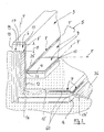
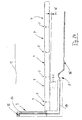
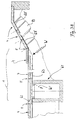
- Fig. 1 is a portion of a total designated 1 Catch pan shown to accommodate environmentally hazardous Liquids are provided and in doing so a recessed floor area 2, for example for industrial plants, Storage containers, transformer systems, loading stations or the like an uncontrolled penetration of pollutants into the Floor area 2, for example in the event of an accident, a leak or the like, is prevented.
- a recessed floor area 2 for example for industrial plants, Storage containers, transformer systems, loading stations or the like an uncontrolled penetration of pollutants into the Floor area 2, for example in the event of an accident, a leak or the like, is prevented.
- the drip pan 1 is made in the inventive design built on the bottom and edge concrete moldings, where in respective joint areas F between the edge molding 3 and bottom molded body 4 provided individual components at least a sealing zone 8, 8 'forming a blocking zone 5, 6, 7 are arranged.
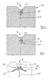
- FIG. 2 shows an enlarged detail representation of edge and base moldings 3 and 4 whose formation with recesses 10, 11 or inside projections 12, which in the case of adjacent laying the molded body has a common receiving groove for the sealant 8, 8 'limit.
- FIG. 2 clarifies this when viewed together 17 shows the formation of the respective exclusion zones 5 and 7 with sealing parts cast into the molded bodies 3, 4 8 'in the form of film material 14, 14' in the edge protrudes the respective joint area or the receiving groove.
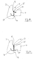
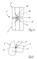
- Fig. 3 is the L-shaped edge molding 4 in an individual representation illustrates, this along its vertical and Horizontal leg 15, 16 with a one-piece continuous Sealing part in the form of the sealing film 14 with the front projecting portion 14 'is provided.
- the edge shaped bodies have 3 different embodiments the vertical exclusion zone 6, which is in the direction of the joint area F vertically in the direction of the leg 15 and horizontally in the direction of the leg 16 of the edge molding 3 extends.
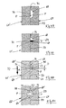
- the edge molding 3 in the region of the mutually facing transverse sides 17, 18 with a Groove / tongue profiling 19 (Fig. 2, Fig. 3) provided by which a precisely fitting toothing of the molded body is possible in this way (Fig. 4 to 6) that for repair purposes individual the edge molding 3 also released from the connection position and afterwards again connected to each other or to the bottom moldings 4 can be.
- this is in the receiving groove protruding sealing film 14 in the edge stones 3 over the end Barb 21 fixed and in the area of the restricted zone 6 provided with a seam 22 produced by welding or gluing.
- the sealing film has 14 multiple barbs 21 'on and in the embodiment 6 is a pourable as an additional sealant Sealant 23 introduced into the receiving groove and spaced via a cord 24 made of foam to the seam 22.
- Sealant 23 introduced into the receiving groove and spaced via a cord 24 made of foam to the seam 22.
- a sealant Pour polysulfide in the longitudinal direction of the entire receiving groove, so that the blocking zone 6 is double-secured with the seam 22 and the sealing compound 23, which also extends along of the horizontal leg 16 up to its end face with the Foil area 14 can extend.
- the two sealants 23 and 23 ' In the area of the molding 12 (Fig. 2) intersect the two sealants 23 and 23 ', so that the exclusion zone 5 is formed.
- FIGS. 7 to 9 show a change in the area of the tongue and groove profile 19, with an additional Receiving chamber 25 for the respective seam 22 of the sealing films 14 is provided and the sealant 23 with the Cord 24 directly adjoins the groove profile 19 '.
- Fig. 10 is in the respective edge molding 3 in the longitudinal direction extending perforated plastic sheet or the like.
- a sealing film 14 "cast in Fig. 11 is the sealing film 14" as a fabric part having holding fibers 27 is formed and in 12 is the sealing film 14 "'over a connector 28 on a cast structural reinforcement 29 stably hooked.
- FIG. 12 Similar to the embodiment according to FIG. 12, one in FIG continuous, in particular wavy fabric web 30 made of oriented fibers or nonwoven material, which is glued to the receiving groove with the sealing film 14 '' '.
- an additional connecting means in the form of an Plastic part cast in or used during assembly 31 provided.
- the tongue and groove profile a receiving chamber 25 'encapsulated with polysulfide seal 32 on the bottom side with a foam layer 33 (FIG. 16) is filled in such a way that the polysulfide layer 32 is elastically supported and has only one flank 26, 26 'existing liability of the reception chamber are cracks in the Sealant for slight displacements of the molded edge 3 avoided.
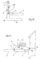
- FIG. 17 to 19 show the connection position the bottom molding 4 in the area of the inside molding 11 on the L-shaped edge shaped bodies 3, the horizontal legs 16 the edge molding 3 the bottom molding 4 in reach under a distance A. It is like a synopsis with Fig. 1 becomes clear in the horizontal section of the sump 1 a double-layer securing through the interaction the exclusion zones 5, 6 and 7 reached.
- the lower exclusion zone 7 is of the catch pan 1 over the entire surface below the bottom molded body 4 and with the Sealing parts 14 of the edge molding 3 connected sealing film 36 formed.
- the sealing film 14 is in the restricted area 6 shown in two layers
- Fig. 18 is the sealing film 14 only in the area of the vertical leg 15 up to the exclusion zone 5 provided
- Fig. 19 shows a double-layer version with a short extension to restricted area 5.
- FIG. 20 and 21 show the enlarged representations expedient embodiments in the area of the exclusion zone 5 between the bottom moldings 4 and the inside molding 12 on the L-shaped shaped edge body 3.
- the web-shaped Plastic parts 37, 38 as a sealant in the area a seam 22 'connected, and this is as an additional Fuse the polysulfide sealant 40 (Fig. 21) introduced.
- Fig. 22 the blocking zone 7 'is at the front end of the horizontal leg 16 provided with the formation 12 'in the area both the sealing film 14 ', 14 are connected as well Sealant 23 are introduced so that the sump 1 according to 23 is formed.
- Fig. 23 to 28 show further embodiments the sump 1.
- Fig. 23 is a complete one Cross section with enlarged horizontal leg 16 L-stones 3 and on the foot side of this Bottom moldings 4 shown (Fig. 22)
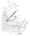
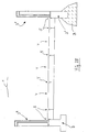
- Fig. 24 shows the Collecting trough 1 with an inclined N shaped body 4 similar to Fig. 1, with the sump on one side is open and passable.
- the edge molding 3 ′′ have respective support feet S, S ′, which are underneath, for example, a concrete layer B.
- the shaped concrete bodies 4 delimit to a bearing surface 43 provided as a basement wall a sealing film 44 screwed on the one hand and to each assigned bottom molded body 4 is welded on the other hand (Fig. 26).
- FIG. 28 shows a drivable drip pan 1 ', in which on the one hand an edge molding 3' in a sealing connection stands with a driving surface 45 and starting from this the bottom molding 4 forming the collecting trough 1 'up to an otherwise provided limit with the L-shaped Edge shaped bodies 3 are laid with a slope N '.
- the inner one Driving surface 45 'on the top of the floor molding 4 has Sealant largely lowered in the grooves 8, 8 ', so that in this passable version Damage to exclusion zone 5 from vehicle tires avoided is.
- 29 to 32 are similar to the joint designs in the area the L-shaped body 3 the connection options the cast sealing foils 14 are shown in the base moldings 4, the design features with the embodiment 4 to 6 are comparable and thus in these respective exclusion zones 5, 7 'essentially the same, long-term stable Sealing conditions have been reached.
- the seals described above are in the grooves between edge molding 3 and bottom molding 4 in Area of the sealing means 8, 8 'or the sealing foils 14, 14' see above designed that if one of the blocking zones 5 is damaged, 6, 7, 7 '(by means of the measuring probes 42, 42' on the liquid detection is detectable), the moldings concerned in each case 3, 4 can be replaced and then the severed sealing areas or restricted areas without any problems are recoverable.
- Shaped bodies 3, 4 is sealing film 14, particularly in areas with high pressure loads, e.g. at the edge of the drip pan 1, with an extended reserve part R at the upper end provided (Fig. 24) so that after inserting an adjacent new molding this part R a renewed welding or gluing.
- the tongue / groove profiling 19 can in an advantageous embodiment with a low tooth depth Z (Fig.
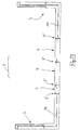
- 33 to 36 are the laying conditions during manufacture shown the bottom of the tub, the respective bottom molded body 4 on a base layer 46 of ballast or lean concrete and a formation layer 47, for example made of sand, are hung up. This is followed by solidification in this installation position by means of a vibrator 48, also in the receiving grooves fillers 55 (FIG. 35) are solidified (Arrow R).
- the opposite Molded base 4 mutually in respective areas 52 and 53 of the short side and the bottom side with a Adhesion-preventing material, such as a wax, coated.
- a Adhesion-preventing material such as a wax
- the filling sand introduced is 55 (Fig. 33) by means of an adhesive entry (filling member 60, Fig. 34) at least in regions to a plug 54, 54 '(Fig. 35, Fig. 36) solidified on the coating areas 52 and 53 is not liable, so that a balance of horizontal and / or vertical movements is possible.
- the Floor moldings 4 are rectangular paving stones only two adjoining side surfaces with the wax layer provided so that in the laying position coated and uncoated Areas in the receiving groove face each other.
- this measure is a postponement of the Sand 55 'from the formation layer 47 and the sand 55 from the Prevents grooves and the top polysulfide layer 23 remains undamaged under pressure loads.
- the embodiment shown in FIG. 36 shows an adhesive entry (FIG. 34), which extends into the area of the formation layer 47 took place, so that with an enlarged plug 54 ' Edge areas of the stones 3 are detected and their tilting movement is prevented.
- the sand 55 present in this area can do not drain and into the area of the polysulfide insert 23 parts of the formation layer cannot be postponed.
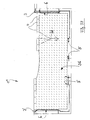
- FIG. 37 shows a drip pan 1 ", the complete with a filler 56 up into the top Edge area of the L-shaped stones 3 '(left side of the figure) filled is similar, so that a passability in this area 28 is achieved.
- the representation ends the laying plane of the shaped base body 4 below the upper edge of the edge molding 3.
- the out Filling layer formed from special biologically active materials 56 provided as a conversion space for pollutants is. This can be used, for example, as a transshipment point trained floor moldings 4 unwanted leaking liquids derived via the grooves and in the filling layer 56 biodegradable. Through this biological Degradation decreases the concentration of environmentally hazardous Fabrics in a direction H to the tub floor, so that the Tub body 1 'with simple exclusion zones 5 and 6 the security requirements justice.
- the in different designs and installation positions as a sealing membrane used film 14, 14 ', 14' ', 14' '' is at least in some areas on the molded body in the connecting position upper side with a roughened adhesive structure 60 (Fig. 2) provided for the introduced into the joint area Polysulfide 23 enables improved adhesion.
- the roughened Structure 60 ' can be of one during film manufacture generated profile or a subsequently incorporated Structural change must be formed.
- the polysulfide grouting is between the shaped bodies of the sump 1 Long-term stable and slight shifts can be made without cracking in the area of the film 14 and / or the polysulfide 23 be balanced.
- Fig. 38 the bucket 1 is in an inclined position located floor moldings 4 provided, being in the horizontal A drainage shaft 61 in the area of the drain pan integrated for groundwater on the ground.
- the top with a cover 62 fluid-tight to the receiving space of the tub closed collecting container 61 has one adjacent Molded base 4 at least in some areas Drainage plate 63, by means of which only the arrow W groundwater shown at W 'introduced into the collecting shaft 61 can be.
- This is damage to the floor moldings 4 or the seals in the area of joint F due to groundwater reliably avoided.
- the bottom moldings 4 still in the inclined area of a protective film 63 ' Undermined, for example, from a on the concrete layer B glued geotextile and the groundwater to the drainage plate 63 leads.
- Fig. 39 is the bottom shaped body designed as a hexagon 64 4 shown in a plan view, with its respective Side flanks provided plastic parts 65, in particular made of foam.
- the one about Part area of the side surface extending foam parts 65 can be glued after the production of the molded body 3 or 4 be (Fig. 41) or already in the manufacture of the corresponding Concrete molded body 64 via a retaining shoulder 66 in the molded body can be integrated (Fig. 42 to 45). In the laying position each cover the foam parts 65 Part of Fugue F.
- the foam parts 65th each extend over a portion of the side surface and with this juxtaposition of the hexagon stones 64 a closure the receiving groove or the joint F in the manner of that already shown in FIG. 2 shown cord 24 is formed.
- the plastic parts 65 are advantageous on the shaped bodies 4 (or 3, Fig. 44, 45) determined that a complex assembly when laying the Components on the construction site is unnecessary.
- the filling sand 55 can be introduced and then the pourable sealant 23, for example in the form of polysulfide, for the final closure of the Fug F can be applied.
- FIG. 44 Joint structure F in the area of a vertical joint of the L-shaped Shaped edge body 3 shown (similar to Fig. 8), the sealant 23 is introduced in the form of filler.
- the 45 shows the foam body 65 in Connection with a formation of the joint shape similar to FIG. 21, wherein the shaped body 3 and at the bottom of the tub body 1 4 adjoin each other.
- Fig. 46 are shaped bottom blocks 67 formed as rectangular stones 4 shown, which are also in the area of a joint F.
- the cross-sectional representations according to FIGS. 47 to 51 show (according to a section line A-A in FIG. 46) an embodiment of sealing chambers 68 on the side surfaces of the stones 67, with at least one foam part 69 in the chambers 68 is glued in.
- 48 shows the one hand provided sealing chamber 68 on the stone 67 and the assigned stone 67 'is provided with a marking edge 70, when filling the liquid sealant 23 (Fig. 49) allows easy control of the fill level.
- a primer effective as an adhesion promoter and the sealing compound 23 are in the longitudinal direction of the joints F, respectively Filling openings 71 (Fig. 46) recessed so that similar to Embodiment according to FIG. 34 via a filling member 60 of the entry of the liquid sealant is possible.
- these chambers 68 is the multi-layer joint seal against external damage protected.
- the sealing material 23 is made of two and four foam parts 69, 69 'surround, the sealing material 23 only with respective in the sealing chamber 68 or perpendicular to the side surface of the opposite stone 67 ' extending surface areas P is glued.
- the sealing material 23 is only deformed so that a Damage to the joint tightness is avoided and in the area the mutually supported side surfaces of the shaped bodies 67 and 67 'local overloads from the individual stones and the Sealing system can be included without damage.
- Over a wedge-shaped Gaps 77 (FIGS. 47, 51) can form contours of the stones these are positioned in an inclined installation position, whereby overloading of the edges in the area of the gap 77 is avoided are.
- the sealing compound 23 has in the joint F or the chamber 68 a cross-section, which by means of the foam parts 69, 69 ' formed with a medium material contour of small thickness D. is. This makes it elastically stretchable after the filling process Sealant 23 for optimal load absorption in this way dimensioned that an unwanted tearing of the sealing material 23rd avoided by the stones (in area P) and in the above Pressure loads (arrow 72) zone D according to Art a predetermined deformation line in the longitudinal direction of the joint is effective.
- the respective lower foam parts 69 dimensioned so that an unwanted leakage of the liquid Sealant is prevented when filling.
- a subsequent tightness check in the area of the joints F is in sections between neighboring areas with little effort Filling openings 71 possible, this with a plug part be closed and then by means of a joint F suction cup positioned on the stones (not shown) a vacuum test can be carried out so that environmental hazards safely avoided in the area of the sump 1 become.
Abstract
Description
Die Erfindung betrifft eine Auffangwanne, insbesondere zur Aufnahme
von umweltgefährdenden Flüssigkeiten, gemäß dem Oberbegriff
des Anspruches 1; siche DE-A- 43 36 570.The invention relates to a drip pan, in particular for receiving
of environmentally hazardous liquids, according to the generic term
of
Bekannte Auffangwannen sind zur Aufnahme von umweltgefährdenden Flüssigkeiten als Sicherungsunterbauten vorgesehen, die eine vor Ort gegossene Bodenplatte und an diese randseitig anschließende Seitenwandungen aufweisen. Zur vollständigen Abdichtung ist die Auffangwanne mit Folienbahnen ausgekleidet, die bei der Installation von Industrieanlagen, Vorratsbehältern, Trafoanlagen oder dgl. beschädigt werden können und die Befahrbarkeit derartiger Auffangwannen ist weitgehend eingeschränkt.Known drip pans are used to hold environmentally hazardous Liquids are provided as fuse bases, the one cast on-site base plate and adjoining this on the edge Have side walls. For complete sealing the drip pan is lined with foil sheets, the installation of industrial plants, storage containers, Transformer systems or the like can be damaged and the accessibility of such sumps is largely restricted.
Die Erfindung befaßt sich mit dem Problem, eine Auffangwanne zu schaffen, deren Boden- und Seitenwandungen mit geringem technischem Aufwand eine langzeitstabile Dichtigkeit auch bei Befahrbarkeit der Auffangwanne gewährleisten, wobei diese auch nach Auftreten einer Undichtigkeit ohne zwischenzeitliche Verunreinigungen des Unterbodens mit geringem Aufwand reparierbar ist.The invention is concerned with the problem of a drip pan create whose bottom and side walls with little technical Effort for long-term tightness even when it can be driven on Ensure the drip pan, which also after a leak has occurred without any interim contamination of the underbody can be repaired with little effort is.
Ausgehend von einer Auffangwanne nach dem Oberbegriff des Anspruches
1 löst die Erfindung diese Aufgabe mit den Merkmalen
des kennzeichnenden Teils des Anspruches 1. Hinsichtlich
wesentlicher weiterer Ausgestaltungen wird auf die Ansprüche 2
bis 16 verwiesen.Starting from a sump according to the preamble of the
Die erfindungsgemäße Auffangwanne ist als eine Verbundbaueinheit ausgebildet, deren Wandungskonturen bodenseitige und randseitige Beton-Formkörper als Einzelbauteile aufweisen. Diese Formkörper bilden in Einbaulage vertikal und horizontal verlaufende Fugen als jeweilige Aufnahmenuten, derart, daß ein darin vorgesehenes Dichtungsmittel als Sperrzone für Flüssigkeiten wirksam ist und die aus Beton gegossenen Formkörper integraler Teil einer insgesamt fluiddichten Stützkonstruktion sind.The drip pan according to the invention is a composite unit trained, the wall contours bottom and edge Have concrete moldings as individual components. This Shaped bodies form vertically and horizontally in the installed position Grooves as respective grooves, such that a sealant provided therein as a barrier zone for liquids is effective and the molded body cast from concrete integral part of an overall fluid-tight support structure are.
Auf den Bodenformkörpern kann dabei ein die umweltgefährdende Flüssigkeit enthaltender Behälter abgestützt sein oder der Wannenboden ist insgesamt befahrbar, so daß beispielsweise auch ein Mineralöl enthaltendes Tankfahrzeug oder dgl., in die Auffangwanne einfahren kann. Auch bei diesen rauhen Betriebsbedingungen sind Beschädigungen der Sperrzone langzeitstabil vermieden und ungewollt austretende Flüssigkeit verbleibt in der Auffangwanne. Über sowohl den Bodenbereich als auch den Randbereich des Wannenkörpers umfassende Sperrzonen ist ein Eindringen der Flüssigkeit in den Bereich des Unterbodens auch bei einer Havarie zuverlässig verhindert. Zusätzlich sind in den Bereich der Sperrzonen diese untergreifende Meßfühler eingebracht, so daß auftretende Undichtigkeiten geortet und die Schadstelle ohne Gefährdung des Unterbodens ausgebessert werden kann. On the floor moldings can be an environmentally hazardous Container containing liquid or the Trough floor is passable overall, so that for example a tanker or the like containing mineral oil into the sump can drive in. Even in these harsh operating conditions damage to the exclusion zone is avoided with long-term stability and unintentionally escaping liquid remains in the Drip pan. Over both the bottom area and the edge area exclusion zones of the tub body are intrusion the liquid in the area of the underbody too of an accident reliably prevented. In addition, in the In the area of the restricted zones so that occurring leaks are located and the Damaged area can be repaired without endangering the underbody can.
Die Beton-Formkörper sind in zweckmäßiger Ausführung mit jeweils bei der Herstellung eingegossenen Dichtungsbahnen versehen, die randseitig in die Aufnahmenut vorstehen und hier über eine Schweiß- oder Klebenaht fluiddicht verbunden sind. Über eine zusätzlich in die Aufnahmenut eingebrachte Dichtungsmasse, beispielsweise einen Polysulfid-Kleber, kann ein die Sicherheit der Sperrzone insgesamt noch verbessernde Nutfüllung erreicht werden.The concrete moldings are in an appropriate design with each provided with cast geomembranes during manufacture, that protrude into the receiving groove on the edge and here are connected fluid-tight via a weld or adhesive seam. Via an additional sealing compound introduced into the receiving groove, For example, a polysulfide adhesive, a Security of the exclusion zone as a whole still improving groove filling can be achieved.
Die in befahrbaren Bereichen der Aufnahmewanne angeordneten Boden- und Randformkörper sind in ihren fugenseitigen Aufnahmenuten durch einen mehrschichtigen Füllungsaufbau zusätzlich gegen Belastungen durch Fahr- und Bremskräfte gesichert. Durch einen auf dem Nutgrund vorgesehenen Verschlußteil in Form eines Pfropfens wird ein Einpressen von bodenseitigem Material, beispielsweise Sand, in den unteren Fugebereich vermieden, damit eine Verdrängung des in der Nut befindlichen Füll- und Dichtmittels auch bei hohen dynamischen Belastungen der Bodenformkörper verhindert und ein Schutz für die oberseitige Dichtmittel-Sperrzone ist damit auch unter rauhen Betriebsbedingungen, beispielsweise im Bereich einer Verladestation mit hohen Fahrzeugbelastungen, langzeitig gewährleistet. Die Dichtmittel-Sperrzonen sind dabei zweckmäßig so angeordnet, daß auch bodenseitig drückendes Grundwasser abgeschirmt ist.The arranged in passable areas of the receptacle Bottom and edge moldings are in their joint-side grooves thanks to a multi-layer filling structure secured against loads from driving and braking forces. By a closure part provided in the groove base in the form a plug becomes a pressing in of bottom material, for example sand, avoided in the lower joint area, thus a displacement of the filling and Sealant even with high dynamic loads Molded floor prevents and protection for the top Sealant barrier zone is therefore also under rough operating conditions, for example in the area of a loading station with high vehicle loads, guaranteed long-term. The sealant barrier zones are expedient arranged that groundwater pressing groundwater is shielded is.
In vorteilhafter Weiterbildung dieser Stütz- und Dichtkonstruktion kann die Auffangwanne im Bereich unterhalb der Bodenformkörper mit einer im wesentlichen bodenparallelen Dichtfolie als zusätzliche Sperrzone versehen sein. Die Folien-Dichtmittel im Bereich der L-förmigen Randformkörper sind dabei beispielsweise über eine Klebeverbindung der Boden-Dichtfolie so zugeordnet, daß die Auffangwanne von einer parallelen Sicherungswanne untergriffen ist. Dieser Sicherungsunterbau wird höchsten Anforderungen auch gegen stauendes Grundwasser gerecht, da dieses im Bereich einer Dainage unterhalb der Aufwangwanne abgeleitet wird.In an advantageous development of this support and sealing structure can the drip pan in the area below the bottom molded body with a sealing film that is essentially parallel to the floor be provided as an additional exclusion zone. The film sealant in the area of the L-shaped edge shaped bodies are, for example assigned to the floor sealing film via an adhesive connection that the drip pan from a parallel fuse pan is undermined. This fuse base will be the highest Meets requirements even against stagnant groundwater, because this is derived in the area of a drainage below the bucket becomes.
Weitere Einzelheiten und Vorteile der Erfindung ergeben sich aus der nachfolgenden Beschreibung und den Zeichnungen, die mehrere Ausführungsbeispiele einer erfindungsgemäßen Auffangwanne veranschaulichen. In der Zeichnung zeigen:
- Fig. 1
- eine teilweise geschnittene Prinzipdarstellung der erfindungsgemäßen Auffangwanne mit jeweiligen randseitigen und bodenseitigen Formkörpern aus Beton,
- Fig. 2
- eine vergrößerte Ausschnittsdarstellung im Verbindungsbereich eines Randformkörpers mit einem Bodenformkörper,
- Fig. 3
- eine vergrößerte Einzeldarstellung des L-förmigen Randformkörpers in Einbaulage,
- Fig. 4 bis Fig. 15
- jeweilige Draufsichten zweier in Einbaulage befindlicher Randformsteine mit einer eine Aufnahmenut bildenden Fuge, mit verschiedenen Ausführungsformen eines Dichtungsmittels,
- Fig. 16
- eine vergrößerte Ausschnittsdarstellung eines Dichtungsmittels im Bereich der Aufnahmefuge gemäß Fig. 14,
- Fig. 17 bis Fig. 19
- jeweilige Ausschnittsdarstellungen des Bodenformkörpers und des Randformkörpers ähnlich Fig. 2 mit unterschiedlichen Ausführungen der Dichtungsmittel im Verbindungsbereich,
- Fig. 20 und Fig. 21
- vergrößerte Ausschnittsdarstellungen einer innenseitigen Anformung des Randformsteines und die mit dem Bodenformstein gebildete Aufnahmenut,
- Fig. 22
- eine Ausschnittsdarstellung eines L-förmigen Randformsteines mit an dessen Horizontalschenkel anliegendem Bodenformstein,
- Fig. 23 bis Fig. 28
- jeweilige Querschnittsdarstellungen der Auffangwanne ähnlich Fig. 1 mit unterschiedlicher Ausbildung der Sperrzone,
- Fig. 29 bis Fig. 32
- jeweilige Einzeldarstellungen von Aufnahmenuten zwischen den Bodenformkörpern mit unterschiedlichen Dichtungsausführungen,
- Fig. 33
- eine Querschnittsdarstellung von zwei Bodenformkörpern auf bodenseitigen Tragschichten,
- Fig. 34
- eine Prinzipdarstellung ähnlich Fig. 33 beim Verfüllen der Aufnahmenut,
- Fig. 35 und Fig. 36
- jeweilige vergrößerte Ausschnittsdarstellungen im Bereich der Aufnahmenut zwischen den Bodenformsteinen ähnlich Fig. 34 mit einem im Bereich der Aufnahmenut erzeugten Verschlußpfropfen,
- Fig. 37
- eine Querschnittsdarstellung der Aufnahmewanne ähnlich Fig. 1 mit gleichebnig mit den Randformkörpern angeordneten Bodenformkörpern und einem unter diesen vorgesehenen Schichtaufbau,
- Fig. 38
- eine Ausschnittsvergrößerung der Aufwangwanne mit geneigtem Seitenwandbereich und einem bodenseitigen Entwässerungsschacht,
- Fig. 39
- eine Draufsicht des sechseckigen Bodenformkörpers mit an dessen Seitenflächen vorgesehenen Schaumstoffteilen,
- Fig. 40
- eine Ausschnittsdarstellung als Draufsicht mehrerer der Bodenformkörper in Einbaulage,
- Fig. 41 bis Fig. 43
- jeweilige Querschnittsdarstellungen der Aufnahmenut zwischen den Bodenformkörpern mit Schaumstoffteilen,
- Fig. 44
- eine Draufsicht ähnlich Fig. 8 mit der zwischen den Randformkörpern gebildeten Aufnahmenut,
- Fig. 45
- eine Schnittdarstellung ähnlich Fig. 20 mit dem Schaumstoffteil in der Aufnahmenut,
- Fig. 46
- eine geschnittene Draufsicht auf mehrere rechteckige Bodenformkörper im Bereich der gemeinsamen Aufnahmenuten, und
- Fig. 47 bis Fig. 51
- jeweilige Schnittdarstellungen von aneinanderliegenden Formkörpern mit zusätzlichen Formnuten in der Seitenfläche.
- Fig. 1
- a partially sectioned schematic representation of the collecting trough according to the invention with respective edge-side and bottom-side shaped bodies made of concrete,
- Fig. 2
- 2 shows an enlarged detail view in the connection area of a shaped edge body with a shaped bottom body,
- Fig. 3
- an enlarged individual view of the L-shaped molded body in the installed position,
- 4 to 15
- respective top views of two edge shaped stones in the installed position with a joint forming a receiving groove, with different embodiments of a sealant,
- Fig. 16
- 14 shows an enlarged detail of a sealant in the region of the receiving joint according to FIG. 14,
- 17 to 19
- respective sectional representations of the shaped base body and the shaped edge body similar to FIG. 2 with different designs of the sealing means in the connection area,
- 20 and 21
- Enlarged detail representations of an inside molding of the edge molding and the receiving groove formed with the bottom molding,
- Fig. 22
- 2 shows a detail of an L-shaped edge stone with a bottom stone lying against its horizontal leg,
- 23 to 28
- respective cross-sectional representations of the drip pan similar to FIG. 1 with different design of the exclusion zone,
- 29 to 32
- respective individual representations of grooves between the shaped base bodies with different seal designs,
- Fig. 33
- 2 shows a cross-sectional representation of two shaped floor bodies on base-side base layers,
- Fig. 34
- 33 shows a basic illustration similar to FIG. 33 when filling the receiving groove,
- 35 and 36
- respective enlarged detail views in the area of the receiving groove between the shaped base stones similar to FIG. 34 with a closure plug produced in the area of the receiving groove,
- Fig. 37
- 2 shows a cross-sectional illustration of the receiving trough similar to FIG. 1 with bottom shaped bodies arranged level with the edge shaped bodies and a layer structure provided underneath them,
- Fig. 38
- an enlarged section of the sump with an inclined side wall area and a drainage shaft on the bottom,
- Fig. 39
- 2 shows a plan view of the hexagonal shaped base body with foam parts provided on its side surfaces,
- Fig. 40
- 2 shows a cutout view as a top view of several of the shaped base bodies in the installed position,
- 41 to 43
- respective cross-sectional representations of the receiving groove between the base moldings with foam parts,
- Fig. 44
- 8 with the receiving groove formed between the edge shaped bodies,
- Fig. 45
- 20 shows a sectional illustration similar to FIG. 20 with the foam part in the receiving groove,
- Fig. 46
- a sectional plan view of several rectangular shaped bodies in the area of the common grooves, and
- 47 to 51
- respective sectional views of adjoining moldings with additional grooves in the side surface.
In Fig. 1 ist ein Teilbereich einer insgesamt mit 1 bezeichnete
Auffangwanne dargestellt, die zur Aufnahme von umweltgefährdenden
Flüssigkeiten vorgesehen ist und dabei einen in
einen Bodenbereich 2 eingelassenen, beispielsweise für Industrieanlagen,
Vorratsbehälter, Trafoanlagen, Verladestationen
oder dgl. vorgesehenen Sicherheitsunterbau definiert, mittels
dem ein unkontrolliertes Eindringen von Schadstoffen in den
Bodenbereich 2, beispielsweise bei einer Havarie, einer Leckage
o. dgl., verhindert ist. In Fig. 1 is a portion of a total designated 1
Catch pan shown to accommodate environmentally hazardous
Liquids are provided and in doing so
a recessed
Die Auffangwanne 1 ist in erfindungsgemäßer Ausführung aus
bodenseitigen und randseitigen Beton-Formkörpern aufgebaut, wobei
in jeweiligen Fugenbereichen F zwischen den als Randformkörper
3 und Bodenformkörper 4 vorgesehenen Einzelbauteilen zumindest
eine Sperrzone 5, 6, 7 bildende Dichtungsmittel 8, 8'
angeordnet sind.The
In Fig. 2 verdeutlicht eine vergrößerte Ausschnittsdarstellung
von in Einbaulage befindlichen Rand- und Bodenformkörpern 3 und
4 deren Ausbildung mit randseitigen Ausnehmungen 10, 11 bzw.
innenseitigen Anformungen 12, die bei benachbarter Verlegung
der Formkörper eine gemeinsame Aufnahmenut für die Dichtungsmittel
8, 8' begrenzen.2 shows an enlarged detail representation
of edge and
Die Darstellung gemäß Fig. 2 verdeutlicht dabei in Zusammenschau
mit Fig. 17 die Ausbildung der jeweiligen Sperrzonen 5
und 7 mit in die Formkörper 3, 4 eingegossenen Dichtungsteilen
8' in Form von Folienmaterial 14, 14' das randseitig in
den jeweiligen Fugenbereich bzw. die Aufnahmenut vorsteht. In
Fig. 3 ist der L-förmige Randformkörper 4 in Einzeldarstellung
veranschaulicht, wobei dieser entlang seines Vertikal- und
Horizontalschenkels 15, 16 mit einem einteilig durchgehenden
Dichtungsteil in Form der Dichtfolie 14 mit dem stirnseitig
vorstehenden Teilbereich 14' versehen ist.The illustration according to FIG. 2 clarifies this when viewed together
17 shows the formation of the
In Fig. 4 bis 15 verdeutlichen jeweilige Draufsichten von in
Einbaulage befindlichen Randformkörpern 3 unterschiedliche Ausführungsformen
der vertikalen Sperrzone 6, die sich in Richtung
des Fugenbereiches F vertikal in Richtung des Schenkels 15 und
horizontal in Richtung des Schenkels 16 der Randformkörper 3
erstreckt. In zweckmäßiger Ausführung sind die Randformkörper 3
im Bereich der einander zugewandten Querseiten 17, 18 mit einer
Nut/Feder-Profilierung 19 (Fig. 2, Fig. 3) versehen, mittels
der eine paßgenaue Verzahnung der Formkörper derart möglich ist
(Fig. 4 bis 6), daß zu Reparaturzwecken einzelne der Randformkörper
3 auch aus der Verbindungsstellung gelöst und danach
wieder untereinander oder mit den Bodenformkörpern 4 verbunden
werden können.4 to 15 illustrate respective top views of in
In the installed position, the edge shaped bodies have 3 different embodiments
the
In der Ausführungsform gemäß Fig. 4 ist die in die Aufnahmenut
vorstehende Dichtfolie 14 in den Randformsteinen 3 über endseitig
Widerhaken 21 festgelegt und im Bereich der Sperrzone 6
mit einer durch Schweißen oder Kleben erzeugten Naht 22 versehen.
In der Ausführungsform gemäß Fig. 5 weist die Dichtfolie
14 mehrere Widerhaken 21' auf und in der Ausführungsform
gemäß Fig. 6 ist als zusätzliches Dichtungsmittel eine gießfähige
Dichtungsmasse 23 in die Aufnahmenut eingebracht und
über eine Kordel 24 aus Schaumstoff zur Naht 22 hin beabstandet.
In zweckmäßiger Ausführung ist als Dichtungsmasse
Polysulfid in Längsrichtung der gesamten Aufnahmenut vergossen,
so daß die Sperrzone 6 eine Doppel-Sicherung mit der Naht 22
und der Dichtmasse 23 aufweist, wobei sich diese auch entlang
des horizontalen Schenkels 16 bis an dessen Stirnseite mit dem
Folienbereich 14 erstrecken kann. Im Bereich der Anformung 12
(Fig. 2) verschneiden sich die beiden Dichtungsmassen 23 und
23', so daß die Sperrzone 5 gebildet ist.In the embodiment according to FIG. 4, this is in the receiving groove
protruding sealing
Die Ausführungsformen gemäß Fig. 7 bis 9 zeigen eine Veränderung
im Bereich des Nut/Feder-Profiles 19, wobei eine zusätzliche
Aufnahmekammer 25 für die jeweilige Naht 22 der Dichtfolien
14 vorgesehen ist und die Dichtungsmasse 23 mit der
Kordel 24 unmittelbar an das Nutprofil 19' angrenzt. In Fig. 10
ist in die jeweiligen Randformkörper 3 eine sich in Längsrichtung
erstreckende gelochte Kunststoffbahn oder dgl. als Dichtfolie
14" eingegossen, in Fig. 11 ist die Dichtfolie 14" als
ein Haltefasern 27 aufweisendes Gewebeteil ausgebildet und in
der Ausführungsform gemäß Fig. 12 ist die Dichtfolie 14"' über
einen Verbinder 28 an einer eingegossenen Baustahlarmierung 29
stabil verhakt.The embodiments according to FIGS. 7 to 9 show a change
in the area of the tongue and
Ähnlich der Ausführungsform gemäß Fig. 12 ist in Fig. 13 eine
durchgehend, insbesondere wellenförmig verlaufende Gewebebahn
30 aus gerichteten Fasern oder Vliesmaterial vorgesehen,
die zur Aufnahmenut hin mit der Dichtfolie 14''' verklebt ist.
Im Bereich des Nut/Feder-Profiles 19 ist in der Aufnahmekammer
25 ein zusätzliches Verbindungsmittel in Form eines im
Verbund eingegossenen oder bei der Montage eingesetzten Kunststoffteiles
31 vorgesehen.Similar to the embodiment according to FIG. 12, one in FIG
continuous, in particular
In der Ausführungsform gemäß Fig. 14 weist das Nut/Feder-Profil
eine mit Polysulfid-Dichtung 32 vergossene Aufnahmekammer 25'
auf, die bodenseitig mit einer Schaumstoffschicht 33 (Fig. 16)
so ausgefüllt ist, daß zu dieser hin die Polysulfid-Schicht 32
elastisch abgestützt ist und über eine nur zu zwei Flanken 26,
26' der Aufnahmekammer bestehende Haftung sind Rißbildungen im
Dichtmittel bei geringfügigen Verschiebungen der Randformkörper
3 vermieden.In the embodiment according to FIG. 14, the tongue and groove profile
a receiving chamber 25 'encapsulated with
In der Ausführungsform gemäß Fig. 15 ist eine ähnliche Ausführung
im Bereich des Nut/Feder-Profiles 19 vorgesehen, wobei als
Einsatzteil 34 in den Hinterschneidungen aufweisenden Aufnahmekammern
25' ein in Verbindungsstellung der Randformkörper 3
eingetriebener Keil vorgesehen ist. Die Dichtfolie 14 erstreckt
sich hier unmittelbar aus dem Bereich der Nut/Feder-Profilierung
19 in die Aufnahmenut.15 is a similar embodiment
provided in the area of the tongue and
Die Darstellungen gemäß Fig. 17 bis 19 zeigen die Verbindungsstellung
der Bodenformkörper 4 im Bereich der innenseitigen Anformung
11 an den L-förmigen Randformkörpern 3, wobei die Horizontalschenkel
16 der Randformkörper 3 die Bodenformkörper 4 in
einem Abstand A untergreifen. Damit ist, wie in Zusammenschau
mit Fig. 1 deutlich wird, im Horizontalschnitt der Auffangwanne
1 eine doppellagige Sicherung durch das Zusammenwirken
der Sperrzonen 5, 6 und 7 erreicht. Die untere Sperrzone
7 ist dabei von einer die Auffangwanne 1 vollflächig
unterhalb der Bodenformkörper 4 untergreifenden und mit den
Dichtungsteilen 14 der Randformkörper 3 verbundenen Dichtungsfolie
36 gebildet. In Fig. 17 ist die Dichtfolie 14 im Sperrbereich
6 doppellagig dargestellt, in Fig. 18 ist die Dichtfolie
14 nur im Bereich des Vertikalschenkels 15 bis zur Sperrzone
5 hin vorgesehen und Fig. 19 zeigt eine doppellagige Ausführung
mit kurzem Ansatzteil zur Sperrzone 5 hin.17 to 19 show the connection position
the
Zur Überprüfung der Dichtigkeit der vorbeschriebenen Sperrzonen
5 und 7 kann in einer den Abstand A definierenden
Zwischenschicht 41 zwischen den Bodenformkörpern 4 und der
jeweiligen Folie 36 eine Kontrollsonde 42 vorgesehen sein
(Fig. 1). In Fig. 24 ist diese Ausbildung der Sperrzone 7
ähnlich Fig. 1 mit der Folie 36 näher dargestellt. To check the tightness of the above-mentioned
Die vergrößerten Darstellungen gemäß Fig. 20 und 21 zeigen
zweckmäßige Ausführungsformen im Bereich der Sperrzone 5
zwischen den Bodenformkörpern 4 und der innenseitigen Anformung
12 am L-förmigen Randformkörper 3. Dabei sind die bahnförmigen
Kunststoffteile 37, 38 als Dichtmittel im Bereich
einer Naht 22' verbunden, und über dieser ist als zusätzliche
Sicherung das Polysulfid-Dichtmittel 40 (Fig. 21) eingebracht.
In Fig. 22 ist die Sperrzone 7' am stirnseitigen Ende des Horizontalschenkels
16 mit der Anformung 12' versehen, in deren Bereich
sowohl die Dichtfolie 14', 14 verbunden sind als auch das
Dichtmittel 23 so eingebracht sind, daß die Auffangwanne 1 gemäß
Fig. 23 gebildet ist.20 and 21 show the enlarged representations
expedient embodiments in the area of the
Die Darstellungen gemäß Fig. 23 bis 28 zeigen weitere Ausführungsformen
der Auffangwanne 1. In Fig. 23 ist ein vollständiger
Querschnitt mit vergrößertem Horizontalschenkel 16 aufweisenden
L-Steinen 3 und fußseitig an diesem anliegenden
Bodenformkörpern 4 dargestellt (Fig. 22), Fig. 24 zeigt die
Auffangwanne 1 mit eine Neigung N aufweisenden Bodenformkörpern
4 ähnlich Fig. 1, wobei die Auffangwanne einseitig
offen und befahrbar ist. In der Ausführungsform gemäß Fig. 25
weisen die Randformkörper 3'' jeweilige Stützfüße S, S' auf,
die beispielsweise von einer Betonschicht B untergriffen sind.
In der Darstellung gemäß Fig. 27 grenzen die Betonformkörper 4
an eine als Kellerwandung vorgesehene Anlagefläche 43 an, wobei
eine Dichtfolie 44 einerseits angeschraubt und an den jeweils
zugeordneten Bodenformkörper 4 andererseits angeschweißt ist
(Fig. 26). 23 to 28 show further embodiments
the
Die Darstellung gemäß Fig. 28 zeigt eine befahrbare Auffangwanne
1', bei der einerseits ein Randformkörper 3' in Dichtverbindung
mit einer Fahrfläche 45 steht und von dieser ausgehend
die die Auffangwanne 1' bildenden Bodenformkörper 4 bis zu
einer andererseits vorgesehenen Begrenzung mit den L-förmigen
Randformkörpern 3 mit einer Schräge N' verlegt sind. Die innere
Fahrfläche 45' an der Oberseite der Bodenformkörper 4 weist dabei
in den Aufnahmenuten weitgehend abgesenkte Dichtungsmittel
8, 8' auf, so daß in dieser befahrbaren Ausführung eine
Beschädigung der Sperrzone 5 durch Fahrzeug-Reifen vermieden
ist.28 shows a drivable drip pan
1 ', in which on the one hand an edge molding 3' in a sealing connection
stands with a driving
In Fig. 29 bis 32 sind ähnlich den Fugenausbildungen im Bereich
der L-förmigen Randformkörper 3 die Verbindungsmöglichkeiten
der eingegossenen Dichtfolien 14 in den Bodenformkörpern 4 dargestellt,
wobei die konstruktiven Merkmale mit den Ausführungsform
gemäß Fig. 4 bis 6 vergleichbar sind und damit in diesen
jeweiligen Sperrzonen 5, 7' im wesentlichen gleiche, langzeitstabile
Dichtungsbedingungen erreicht sind.29 to 32 are similar to the joint designs in the area
the L-shaped
Gleichzeitig sind die vorbeschriebenen Dichtungen in den Aufnahmenuten
zwischen Randformkörper 3 und Bodenformkörper 4 im
Bereich der Dichtmittel 8, 8' bzw. der Dichtfolien 14, 14' so
ausgelegt, daß bei einer Beschädigung einer der Sperrzonen 5,
6, 7, 7' (die mittels der Meß-Sonden 42, 42' über den Flüssigkeitsnachweis
erfaßbar ist) die jeweils betroffenen Formkörper
3, 4 ausgewechselt werden können und danach die dabei
durchtrennten Dichtungsbereiche bzw. Sperrzonen problemlos
wiederherstellbar sind. At the same time, the seals described above are in the grooves
between
Für die Wiederherstellung von beschädigten Fugenbereichen F
bzw. von darin verlaufenden Sperrzonen bei ausgewechselten
Formkörpern 3, 4 ist die Dichtfolie 14 insbesondere in Bereichen
mit hohen Druckbelastungen, z.B. am Rand der Auffangwanne
1, mit einem verlängerten Reserveteil R am oberen Ende
versehen (Fig. 24), so daß nach dem Einsetzen eines benachbarten
neuen Formkörpers dieser Teil R eine nochmalige Verschweißung
oder Verklebung ermöglicht. Außerdem sind die Formkörper
3 im Bereich der jeweiligen Querseitenfläche 17 bzw. 18
(Fig. 3) mit einer vergrößerten Freifläche P versehen, deren
jeweilige Höhe in Verlegestellung (Fig. 4) einen wiederholt
verfüllbaren Spaltbereich B mit großen Verbindungsflächen, z.B.
für das Polysulfid, definiert. Die Nut/Federprofilierung 19
kann in vorteilhafter Ausführung mit einer geringen Verzahnungstiefe
Z (Fig. 3) ausgebildet sein, so daß beispielsweise
Teil A des Federprofils 19 bei dessen Überbelastung nach Art
einer Sollbruchstelle wirksam wird und eine vollständige Zerstörung
des Verbindungssystems der Formkörper 3 vermieden ist.
Nach einer örtlich begrenzten Beschädigung kann die Auffangwanne
1 mittels einer Teilreparatur bei geringem Aufwand vollständig
abgedichtet werden.For the restoration of damaged joint areas F
or from restricted zones running in it when replaced
In Fig. 33 bis 36 sind die Verlegebedingungen bei der Herstellung
des Wannenbodens dargestellt, wobei die jeweiligen Bodenformkörper
4 auf einer Tragschicht 46 aus Schotter oder Magerbeton
und einer Planumsschicht 47, beispielsweise aus Sand,
aufgelegt sind. Danach erfolgt eine Verfestigung in dieser Einbaulage
mittels eines Rüttlers 48, wobei auch in den Aufnahmenuten
befindlichen Füllstoffe 55 (Fig. 35) verfestigt werden
(Pfeil R). 33 to 36 are the laying conditions during manufacture
shown the bottom of the tub, the respective bottom molded
Diese Nutbereiche zwischen den Steinen 3 stellen insbesondere
bei einer Ausbildung der Auffangwanne 1 als befahrbarer Unterbau
eine durch dynamische Belastungen gefährdete Zone dar, da
es durch Schub- und Druckbelastungen (Pfeile 49 und 50,
Fig. 36) zu Aufschiebungen der im Fugenbereich befindlichen
Sandteile als Füllstoff 55 kommen kann und damit zu einem Anheben
(Pfeil 51) der darüber befindlichen Polysulfidschicht 23,
so daß die Dichtzone insgesamt beschädigt ist.These groove areas between the
Zur Vermeidung dieser Beschädigungszonen verursachenden Materialverschiebungen
in den Aufnahmenuten sind die gegenüberliegenden
Bodenformkörper 4 wechselseitig in jeweiligen Bereichen
52 und 53 der Querseite bzw. der Bodenseite mit einem
Haftung verhindernden Material, beispielsweise einem Wachs, beschichtet.
Gleichzeitig ist der eingebrachte Füllsand 55
(Fig. 33) mittels eines Klebereintrags (Füllglied 60, Fig. 34)
zumindest bereichsweise zu einem Pfropfen 54, 54' (Fig. 35,
Fig. 36) verfestigt, der an den Beschichtungs-Bereichen 52 und
53 nicht haftet, so daß ein Ausgleich von horizontalen und/oder
vertikalen Bewegungen möglich ist. Bei einer Ausbildung der
Bodenformkörper 4 als rechteckige Pflastersteine sind jeweils
nur zwei aneinandergrenzende Seitenflächen mit der Wachsschicht
versehen, so daß in Verlegestellung beschichtete und unbeschichtete
Bereiche in der Aufnahmenut gegenüberliegen.To avoid these material zones causing damage
in the receiving grooves are the opposite
Molded
Insbesondere ist mit dieser Maßnahme ein Aufschieben des
Sandes 55' aus der Planumsschicht 47 bzw. des Sandes 55 aus den
Aufnahmenuten verhindert und die oberseitig befindliche Polysulfidschicht
23 bleibt bei Druckbelastungen unbeschädigt. Die
in Fig. 36 dargestellte Ausführungsform zeigt einen Klebeeintrag
(Fig. 34), der bis in den Bereich der Planumsschicht 47
erfolgte, so daß mit einem vergrößerten Pfropfen 54' die
Kantenbereiche der Steine 3 erfaßt sind und deren Kippbewegung
verhindert ist. Der in diesem Bereich vorhandene Sand 55 kann
nicht abfließen und in den Bereich der Polysulfideinlage 23
können Teile der Planumsschicht nicht aufgeschoben werden.In particular, this measure is a postponement of the
Sand 55 'from the
Die Ausführungsform gemäß Fig. 37 zeigt eine Auffangwanne 1",
die vollständig mit einem Füllmaterial 56 bis in den oberen
Randbereich der L-Randformsteine 3' (linke Seite der Figur) gefüllt
ist, so daß in diesem Bereich eine Befahrbarkeit ähnlich
der Darstellung in Fig. 28 erreicht ist. Auf der rechten Seite
der Darstellung endet die Verlegeebene der Bodenformkörper 4
unterhalb der oberen Randkante der Randformkörper 3. In beiden
dargestellten Fällen sind die Bodenformkörper 4 untereinander
im Bereich ihrer Aufnahmenut nicht abgedichtet, da die aus
speziellen biologisch-aktiven Materialien gebildete Füllschicht
56 als ein Umwandlungsraum für Schadstoffe vorgesehen
ist. Damit können beispielsweise über den als Umschlagplatz
ausgebildeten Bodenformkörpern 4 ungewollt auslaufende Flüssigkeiten
über die Aufnahmenuten abgeleitet und in der Füllschicht
56 biologisch abgebaut werden. Durch diesen biologischen
Abbau nimmt die Konzentration der umweltgefährdenden
Stoffe in einer Richtung H zum Wannenboden hin ab, so daß der
Wannenkörper 1' mit einfachen Sperrzonen 5 und 6 den Sicherheitsanforderungen
gerecht wird.The embodiment according to FIG. 37 shows a
Die in unterschiedlichen Ausführungen und Einbaulagen als Dichtungsbahn
eingesetzte Folie 14, 14', 14'', 14''' ist zumindest
bereichsweise auf der in Verbindungsstellung der Formkörper
oberen Seite mit einer aufgerauhten Haftungsstruktur 60
(Fig. 2) versehen, die für das in den Fugenbereich eingebrachte
Polysulfid 23 eine verbesserte Haftung ermöglicht. Die aufgerauhte
Struktur 60' kann dabei von einer während der Folienherstellung
erzeugten Profilierung oder einer nachträglich eingearbeiteten
Strukturveränderung gebildet sein. Die Polysulfid-Verfugung
zwischen den Formkörpern der Auffangwanne 1 ist damit
langzeitstabil und geringfügige Verschiebungen können ohne Rißbildungen
im Bereich der Folie 14 und/oder des Polysulfids 23
ausgeglichen werden.The in different designs and installation positions as a sealing membrane
used
In Fig. 38 ist die Aufwangwanne 1 mit in geneigter Einbaulage
befindlichen Bodenformkörpern 4 versehen, wobei in den waagerechten
Bereich der Aufwangwanne ein Entwässerungsschacht 61
für bodenseitiges Grundwasser integriert ist. Der oberseitig
mit einem Deckel 62 fluiddicht zum Aufnahmeraum der Wanne hin
verschlossene Sammelbehälter 61 weist eine die angrenzenden
Bodenformkörper 4 zumindest bereichsweise untergreifende
Drainageplatte 63 auf, mittels der nur das mit einem Pfeil W
dargestellte Grundwasser bei W' in den Sammelschacht 61 eingeleitet
werden kann. Damit sind Beschädigungen der Bodenformkörper
4 bzw. der Dichtungen im Bereich der Fuge F durch Grundwasser
zuverlässig vermieden. Zusätzlich sind die Bodenformkörper
4 noch im geneigten Bereich von einer Schutzfolie 63'
untergriffen, die beispielsweise aus einem auf der Betonlage B
aufgeklebten Geotextil besteht und das Grundwasser zur Drainageplatte
63 hin ableitet. In Fig. 38 the
In Fig. 39 ist der als Sechseckstein 64 ausgebildete Bodenformkörper
4 in einer Draufsicht dargestellt, wobei an dessen jeweiligen
Seitenflanken vorgesehene Kunststoffteile 65, insbesondere
aus Schaumstoff, deutlich werden. Die sich über einen
Teilbereich der Seitenfläche erstreckenden Schaumstoffteile 65
können nach der Herstellung der Formkörper 3 bzw. 4 aufgeklebt
werden (Fig. 41) oder bereits bei der Herstellung des entsprechenden
Beton-Formkörpers 64 über einen Halteansatz 66 in
den Formkörper integriert werden (Fig. 42 bis 45). In der Verlegestellung
bedecken die Schaumstoffteile 65 jeweils einen
Teil der Fuge F.In Fig. 39 is the bottom shaped body designed as a
In der Draufsicht gemäß Fig. 40 sind mehrere Steine 64 ausschnittsweise
dargestellt, wobei sich deren Schaumstoffteile 65
jeweils über einen Teilbereich der Seitenfläche erstrecken und
bei dieser Aneinanderlage der Sechsecksteine 64 ein Verschluß
der Aufnahmenut bzw. der Fuge F nach Art der bereits in Fig. 2
dargestellten Kordel 24 gebildet ist. Die Kunststoffteile 65
sind vorteilhaft so an den Formkörpern 4 (bzw. 3, Fig. 44, 45)
festgelegt, daß eine aufwendige Montage bei der Verlegung der
Bauteile auf der Baustelle entbehrlich ist. Unterhalb der jeweiligen
Schaumstoffteile 65 ist der Füllsand 55 einbringbar
und danach kann die gießfähige Dichtungsmasse 23, beispielsweise
in Form von Polysulfid, zum endgültigen Verschluß der
Fuge F aufgetragen werden. In Fig. 44 ist beispielhaft ein
Fugenaufbau F im Bereich einer vertikalen Fuge des L-förmigen
Randformkörpers 3 dargestellt (ähnlich Fig. 8), wobei die Dichtungsmasse
23 in Form von Spachtelmasse eingebracht ist. Die
Darstellung gemäß Fig. 45 zeigt den Schaumstoffkörper 65 in
Verbindung mit einer Ausbildung der Fugenform ähnlich Fig. 21,
wobei am Bodenbereich des Wannenkörpers 1 die Formkörper 3 und
4 aneinandergrenzen.40,
In Fig. 46 sind als Rechtecksteine 67 ausgebildete Bodenformkörper
4 dargestellt, die ebenfalls im Bereich einer Fuge F aneinanderliegen.
Die Querschnittsdarstellungen gemäß Fig. 47 bis
51 zeigen (gemäß einer Schnittlinie A-A in Fig. 46) eine Ausbildung
von Dichtungskammern 68 an den Seitenflächen der Steine
67, wobei in den Kammern 68 zumindest ein Schaumstoffteil 69
eingeklebt ist. Die Darstellung gemäß Fig. 48 zeigt die einerseits
vorgesehene Dichtungskammer 68 an dem Stein 67 und der
zugeordnete Stein 67' ist mit einer Markierungskante 70 versehen,
die beim Einfüllen der flüssigen Dichtungsmasse 23
(Fig. 49) eine einfache Kontrolle der Füllhöhe ermöglicht. Für
das Einbringen eines als Haftverstärker wirksamen Primers und
der Dichtungsmasse 23 sind in Längsrichtung der Fugen F jeweilige
Füllöffnungen 71 (Fig. 46) ausgespart, so daß ähnlich der
Ausführungsform gemäß Fig. 34 über ein Füllglied 60 der Eintrag
des flüssigen Dichtmittels möglich ist. In diesen Kammern 68
ist die mehrlagige Fugendichtung gegen äußere Beschädigungen
geschützt.In Fig. 46 are shaped bottom blocks 67 formed as
In Fig. 50 und 51 ist das Dichtungsmaterial 23 von zwei bzw.
vier Schaumstoffteilen 69, 69' umgeben, wobei das Dichtungsmaterial
23 nur mit jeweiligen in der Dichtungskammer 68 bzw.
an der Seitenfläche des gegenüberliegenden Steines 67' senkrecht
verlaufenden Flächenbereichen P verklebt ist. Bei einer
geringfügigen Verschiebung der Steine (dargestellt mit einem
der Belastungsrichtung entsprechenden Pfeil 72) wird das elastische
Dichtungsmaterial 23 lediglich deformiert, so daß eine
Beschädigung der Fugendichtigkeit vermieden ist und im Bereich
der aneinander abgestützten Seitenflächen der Formkörper 67 und
67' örtliche Überbelastungen von den Einzelsteinen und dem
Dichtungssystem beschädigungsfrei aufgenommen werden können.
Die Steine 67, 67' sind in Einbaulage nur in den bodennahen
Anlagebereichen 73 aneinander abgestützt und an der Oberseite
der Fuge F ist mittels Fasen 74, 75 und einem Spalt 76 eine berührungslose
Einbauposition gebildet. Über einen keilförmigen
Spalt 77 (Fig. 47, 51) bildende Konturen der Steine können
diese in einer geneigten Verlegestellung positioniert werden,
wobei Überbelastungen der Kanten im Bereich des Spaltes 77 vermieden
sind.50 and 51, the sealing
Die Dichtungsmasse 23 weist in der Fuge F bzw. der Kammer 68
einen Querschnitt auf, der mittels der Schaumstoffteile 69, 69'
mit einer mittleren Materialkontur geringer Dicke D geformt
ist. Damit ist die nach dem Einfüllvorgang elastisch dehnbare
Dichtungsmasse 23 für eine optimale Belastungsaufnahme derart
bemessen, daß ein ungewollter Abriß des Dichtungsmaterials 23
von den Steinen (im Bereich P) vermieden und bei den vorbeschriebenen
Druckbelastungen (Pfeil 72) die Zone D nach Art
einer vorgegebenen Deformationslinie in Fugenlängsrichtung
wirksam ist. Dabei sind die jeweiligen unteren Schaumstoffteile
69 so bemessen, daß ein ungewollter Austritt der flüssigen
Dichtungsmasse beim Einfüllen verhindert ist. Die in Fig. 50
und 51 dargestellten oberen Schaumstoffteile 69' ermöglichen
die Verlegung der Steine 67, 67' mit einer Neigung in Längsrichtung
der Fuge F, da beim Einfüllen der Polysulfid-Dichtmasse
deren Verklebung mit dem oberen Randbereich 78 in der
Kammer 68 verhindert ist und die elastisch aushärtende Dichtmasse
den Raum zwischen den oberen Schaumstoffteilen 69' und
den unteren Schaumstoffteilen 69 vollständig ausfüllen kann.The sealing
Eine nachfolgende Dichtigkeitskontrolle im Bereich der Fugen F
ist mit gerinem Aufwand abschnittsweise zwischen benachbarten
Füllöffnungen 71 möglich, wobei diese mit einem Pfropfenteil
verschlossen werden und danach mittels einer über der Fuge F
auf den Steinen positionierten Saugglocke (nicht dargestellt)
eine Unterdruckprüfung vorgenommen werden kann, so daß Umweltgefährdungen
im Bereich der Auffangwanne 1 sicher vermieden
werden.A subsequent tightness check in the area of the joints F
is in sections between neighboring areas with little
Claims (16)
- A collecting vessel made of concrete for receiving hazardous liquids, serving as a safety substructure for industrial plant, storage tanks, transformers, discharging plants, and the like, it having a bottom and a surround going round this, characterised in that the bottom of the collecting vessel (1; 1'; 1'') is comprised of a number of individual purpose-made blocks (4) contiguously laid to form joints (F) sealed from each other by means of a sealing material (8, 8 ') forming at least one exclusion zone, and the rim of the collecting vessel (1; 1'; 1'') is composed of individual rim bricks (3; 3'; 3'') laid for their part side by side with each other and the bottom bricks (4), thus forming joints (F), which are sealed from each other and from the bottom bricks (4) by means of a sealing material (8, 8 ') and having a locking shape (19) on their transverse sides (17, 18) which face each other in the build-in position.
- A collecting vessel as claimed in claim 1, characterised in that the moulded bodies (3, 4) have rim-sided recesses (10,10') or moulded shapes (12; 12') on the inside, which together constitute a receiving groove for the sealing material (8, 8') between the contiguously laid moulded bodies (3, 4).
- A collecting vessel as claimed in claim 1 or 2, characterised in that a pourable sealing compound (23) is provided as the sealing material (8).
- A collecting vessel according to any one of claims 1 - 3, characterised in that the moulded bodies (3, 4) have cast-in sealing parts (8'), which project into the receiving groove on the rim side.
- A collecting vessel according to claim 4, characterised in that the sealing parts (8') projecting into the receiving groove are joined together to form a seal and an upper exclusion zone (5, 6), particularly by welding or bonding them together.
- A collecting vessel according to claim 4 or 5,characterised in that the sealing parts (8, 8') are foil-like (14; 14 '; 14''; 14''').
- A collecting vessel according to claims 1-6, characterised in that the rim bricks (3) are L-shaped, their vertical leg (15) forming the side wall of the receiving vessel (1; 1'; 1'') and with their horizontal leg (16) underpin the bottom bricks (4) in their outer rim area.
- A collecting vessel according to claim 7,characterised in that the horizontal leg (16) of the rim bricks (3) underpin the bottom bricks (4) at a distance of (A).
- A collecting vessel according to any one of claims 4-8, characterised in that the sealing parts (14; 14 '; 14'') of the rim bricks (3) along the vertical and the horizontal legs (15, 16) are of one-piece continuous design.
- A collecting vessel according to any one of claims 4-9, characterised in that the rim bricks (3) on their horizontal leg (16) have a sealing part (14') which projects out from its front end.
- A collecting vessel according to any one of claims 1-10, characterised in that the rim bricks (3), at their transverse sides (17, 18) which face each other in the built-in position, are provided with a tongue and groove section (19).
- A collecting vessel according to any one of claims 1-11, characterised in that below the bottom bricks (4) a sealing foil (36) underpinning all of the collecting vessel (1) and connected to the sealing parts (14, 14') of the rim bricks (3), is provided to serve as a bottom exclusion zone (7).
- A receiving vessel according to claim 12, characterised in that the sealing foil (36), which forms the bottom exclusion zone (7), is arranged at a distance (A') from the bottom bricks (4).
- A collecting vessel according to claim 12 or 13, characterised in that above the bottom exclusion zone (7; 7') there is fitted at least one checking probe (42).
- A collecting vessel according to any one of claims 1-6, characterised in that near the side faces of the bottom bricks (4) there is a coating (52, 53) provided, at least in some areas.
- A receiving vessel according to any one of claims 1-15, characterised in that these (1') have a rectangular peripheral shape, and in a side area the rim bricks (3 ') have a traversable built-in position going towards the inside bottom bricks (4).
Priority Applications (1)
| Application Number | Priority Date | Filing Date | Title |
|---|---|---|---|
| SI9830232T SI0986676T1 (en) | 1997-06-07 | 1998-06-05 | Collecting vessel |
Applications Claiming Priority (3)
| Application Number | Priority Date | Filing Date | Title |
|---|---|---|---|
| DE29709938U | 1997-06-07 | ||
| DE29709938U DE29709938U1 (en) | 1997-06-07 | 1997-06-07 | Drip pan |
| PCT/EP1998/003385 WO1998055701A1 (en) | 1997-06-07 | 1998-06-05 | Collecting vessel |
Publications (2)
| Publication Number | Publication Date |
|---|---|
| EP0986676A1 EP0986676A1 (en) | 2000-03-22 |
| EP0986676B1 true EP0986676B1 (en) | 2002-07-31 |
Family
ID=8041304
Family Applications (1)
| Application Number | Title | Priority Date | Filing Date |
|---|---|---|---|
| EP98929424A Expired - Lifetime EP0986676B1 (en) | 1997-06-07 | 1998-06-05 | Collecting vessel |
Country Status (10)
| Country | Link |
|---|---|
| EP (1) | EP0986676B1 (en) |
| AT (1) | ATE221600T1 (en) |
| AU (1) | AU7918698A (en) |
| CZ (1) | CZ297444B6 (en) |
| DE (2) | DE29709938U1 (en) |
| ES (1) | ES2179510T3 (en) |
| HU (1) | HU226440B1 (en) |
| PL (1) | PL196702B1 (en) |
| SI (1) | SI0986676T1 (en) |
| WO (1) | WO1998055701A1 (en) |
Cited By (1)
| Publication number | Priority date | Publication date | Assignee | Title |
|---|---|---|---|---|
| DE202010003935U1 (en) | 2010-03-19 | 2011-08-01 | Karl Kortmann | Drip tray for holding environmentally hazardous products |
Families Citing this family (2)
| Publication number | Priority date | Publication date | Assignee | Title |
|---|---|---|---|---|
| DE102005053911A1 (en) * | 2005-08-08 | 2007-02-15 | S. Müller Patent Entwicklungs und Verpachtungs GmbH & Co. KG | Retro-fitting tank with leakage protection measures, raises tank, makes base liquid tight and adds tank supports, interceptor and instrumentation |
| DE102015004388A1 (en) | 2015-04-10 | 2016-10-13 | Dieter Swoboda | Safety device for examination and drilling sites in environmentally hazardous areas |
Family Cites Families (17)
| Publication number | Priority date | Publication date | Assignee | Title |
|---|---|---|---|---|
| US698050A (en) * | 1902-01-03 | 1902-04-22 | Sterling T Playford | Sectional tank. |
| DE1038261B (en) * | 1957-02-20 | 1958-09-04 | Chem Fab Gruenau Ag | Method and device for connecting formed components made of a hydraulically setting building material with joint tapes |
| DE1818866U (en) * | 1960-02-20 | 1960-09-29 | Leopold Mueller | REINFORCED CONCRETE PROTECTION TUB FOR HEATING OIL AND FUEL STORAGE TANK |
| DE1821016U (en) * | 1960-09-03 | 1960-11-03 | Leopold Mueller | PROTECTIVE TRAY FOR HEATING OIL AND FUEL STORAGE TANK. |
| FR2173368A5 (en) * | 1972-02-21 | 1973-10-05 | Nicephor Andre | |
| NL7505062A (en) * | 1975-04-29 | 1976-11-02 | Stamicarbon | CONCRETE RESERVOIR COMPOSED OF PREFABRICATED ELEMENTS. |
| EP0411389A1 (en) * | 1989-08-02 | 1991-02-06 | Hans-Jürgen Klatt | Fluid-tight collecting vessel |
| DE59000487D1 (en) * | 1990-03-09 | 1992-12-24 | Stelcon Ag | LIQUID-TIGHT INDUSTRIAL FLOOR COVERING. |
| DE9003844U1 (en) * | 1990-04-03 | 1990-06-13 | Schaup, Reiner | |
| DE9005435U1 (en) * | 1990-05-12 | 1990-07-26 | Becker, Annette, 5300 Bonn, De | |
| DE9109114U1 (en) * | 1991-02-06 | 1991-11-07 | Stelcon Ag, 4300 Essen, De | |
| DE4122413C2 (en) * | 1991-06-11 | 1997-02-13 | Heitkamp Gmbh E | Method and device for producing a collecting space |
| DE9108276U1 (en) * | 1991-07-04 | 1991-10-17 | Straetner, Heinz, 4300 Essen, De | |
| DE9117082U1 (en) * | 1991-11-06 | 1995-10-26 | Helmut Hemmerlein Gmbh & Co Ba | Concrete tub |
| DE4434503A1 (en) * | 1993-09-27 | 1995-03-30 | Schuette Reiner | Liquid-tight roadway |
| DE4336570A1 (en) * | 1993-10-27 | 1995-05-04 | Walter Ludwig Behaelter Stahl | Trough-like or basin-like receiving chamber for water-contaminating liquids stored in storage vessels |
| DE29621187U1 (en) * | 1996-11-19 | 1997-02-06 | Lingen Paul | Multi-layer floor surface with integrated protection for soil and water |
-
1997
- 1997-06-07 DE DE29709938U patent/DE29709938U1/en not_active Expired - Lifetime
-
1998
- 1998-06-05 ES ES98929424T patent/ES2179510T3/en not_active Expired - Lifetime
- 1998-06-05 SI SI9830232T patent/SI0986676T1/en unknown
- 1998-06-05 CZ CZ0439699A patent/CZ297444B6/en not_active IP Right Cessation
- 1998-06-05 PL PL337325A patent/PL196702B1/en not_active IP Right Cessation
- 1998-06-05 EP EP98929424A patent/EP0986676B1/en not_active Expired - Lifetime
- 1998-06-05 HU HU0002947A patent/HU226440B1/en not_active IP Right Cessation
- 1998-06-05 DE DE59805017T patent/DE59805017D1/en not_active Expired - Lifetime
- 1998-06-05 AU AU79186/98A patent/AU7918698A/en not_active Abandoned
- 1998-06-05 WO PCT/EP1998/003385 patent/WO1998055701A1/en active IP Right Grant
- 1998-06-05 AT AT98929424T patent/ATE221600T1/en active
Cited By (1)
| Publication number | Priority date | Publication date | Assignee | Title |
|---|---|---|---|---|
| DE202010003935U1 (en) | 2010-03-19 | 2011-08-01 | Karl Kortmann | Drip tray for holding environmentally hazardous products |
Also Published As
| Publication number | Publication date |
|---|---|
| EP0986676A1 (en) | 2000-03-22 |
| WO1998055701A1 (en) | 1998-12-10 |
| HUP0002947A3 (en) | 2002-01-28 |
| ES2179510T3 (en) | 2003-01-16 |
| AU7918698A (en) | 1998-12-21 |
| DE59805017D1 (en) | 2002-09-05 |
| CZ9904396A3 (en) | 2001-04-11 |
| HU226440B1 (en) | 2008-12-29 |
| SI0986676T1 (en) | 2002-12-31 |
| DE29709938U1 (en) | 1998-10-08 |
| PL196702B1 (en) | 2008-01-31 |
| PL337325A1 (en) | 2000-08-14 |
| CZ297444B6 (en) | 2006-12-13 |
| HUP0002947A2 (en) | 2001-01-29 |
| ATE221600T1 (en) | 2002-08-15 |
Similar Documents
| Publication | Publication Date | Title |
|---|---|---|
| EP0269871A2 (en) | Flooring material | |
| EP0986676B1 (en) | Collecting vessel | |
| DE202006011483U1 (en) | Tank for holding rainwater, effluent, chemicals and other liquids comprises a supply chamber having partially hollow pressing force deviating elements spaced from the wall region | |
| DE102012203818B4 (en) | Ground insert for manhole structures | |
| EP0358857B1 (en) | Drain manhole | |
| DE3809963C2 (en) | ||
| JPH08218410A (en) | Repair method of foundation of fluid storage tank | |
| EP0326892B1 (en) | Upright cylindrical reinforced-concrete containers, especially for storing fluids | |
| EP1252394B1 (en) | System of building components for use in the construction of a foundation | |
| DE4009387C1 (en) | Slope drainage system for rubbish dump - uses porous drainage blocks with sand layer for pressure distribution | |
| CN209816934U (en) | Seepage-proofing structure system of dangerous goods storage yard engineering | |
| DE3719443A1 (en) | Floor covering | |
| DE4015349C2 (en) | ||
| AT228717B (en) | Protective tray | |
| DE2939007A1 (en) | Petrol filling station drainage system - has troughed continuous layered fuel resistant insulating foil below surface or forecourt | |
| DE1181391B (en) | Protective trough for a cylindrical, lying liquid tank | |
| DE102022113081A1 (en) | Gutter element for drainage | |
| DE4215804A1 (en) | Device for sealing floors | |
| CH687261A5 (en) | Mounting for cast-iron frame accommodating manhole cover | |
| DE4434503A1 (en) | Liquid-tight roadway | |
| AT387344B (en) | Refuse tip | |
| DE202005004204U1 (en) | Storage unit for containers either empty or filled, in particular with products of the chemical industry, incorporates a catchment area formed by a plastic sheeting for possible container leakages | |
| DE3714664A1 (en) | Vertical sealing wall for landfill sites | |
| DD144683A1 (en) | WORKING OPENING, PARTICULARLY TUBE PROCESSING IN THE WALL OF A BED TANKS | |
| EP0467050B1 (en) | Collecting basin for polluting liquids set free by leakage |
Legal Events
| Date | Code | Title | Description |
|---|---|---|---|
| PUAI | Public reference made under article 153(3) epc to a published international application that has entered the european phase |
Free format text: ORIGINAL CODE: 0009012 |
|
| 17P | Request for examination filed |
Effective date: 19991130 |
|
| AK | Designated contracting states |
Kind code of ref document: A1 Designated state(s): AT BE CH DE DK ES FI FR GB GR IT LI NL SE |
|
| RAX | Requested extension states of the european patent have changed |
Free format text: SI PAYMENT 19991130 |
|
| GRAG | Despatch of communication of intention to grant |
Free format text: ORIGINAL CODE: EPIDOS AGRA |
|
| 17Q | First examination report despatched |
Effective date: 20011004 |
|
| GRAG | Despatch of communication of intention to grant |
Free format text: ORIGINAL CODE: EPIDOS AGRA |
|
| GRAH | Despatch of communication of intention to grant a patent |
Free format text: ORIGINAL CODE: EPIDOS IGRA |
|
| GRAH | Despatch of communication of intention to grant a patent |
Free format text: ORIGINAL CODE: EPIDOS IGRA |
|
| GRAA | (expected) grant |
Free format text: ORIGINAL CODE: 0009210 |
|
| AK | Designated contracting states |
Kind code of ref document: B1 Designated state(s): AT BE CH DE DK ES FI FR GB GR IT LI NL SE |
|
| AX | Request for extension of the european patent |
Free format text: SI PAYMENT 19991130 |
|
| PG25 | Lapsed in a contracting state [announced via postgrant information from national office to epo] |
Ref country code: GR Free format text: LAPSE BECAUSE OF FAILURE TO SUBMIT A TRANSLATION OF THE DESCRIPTION OR TO PAY THE FEE WITHIN THE PRESCRIBED TIME-LIMIT Effective date: 20020731 Ref country code: FI Free format text: LAPSE BECAUSE OF FAILURE TO SUBMIT A TRANSLATION OF THE DESCRIPTION OR TO PAY THE FEE WITHIN THE PRESCRIBED TIME-LIMIT Effective date: 20020731 |
|
| REF | Corresponds to: |
Ref document number: 221600 Country of ref document: AT Date of ref document: 20020815 Kind code of ref document: T |
|
| REG | Reference to a national code |
Ref country code: GB Ref legal event code: FG4D Free format text: NOT ENGLISH Ref country code: CH Ref legal event code: EP |
|
| REG | Reference to a national code |
Ref country code: CH Ref legal event code: NV Representative=s name: PATENTANWAELTE FELDMANN & PARTNER AG |
|
| REF | Corresponds to: |
Ref document number: 59805017 Country of ref document: DE Date of ref document: 20020905 |
|
| GBT | Gb: translation of ep patent filed (gb section 77(6)(a)/1977) |
Effective date: 20020829 |
|
| PG25 | Lapsed in a contracting state [announced via postgrant information from national office to epo] |
Ref country code: DK Free format text: LAPSE BECAUSE OF FAILURE TO SUBMIT A TRANSLATION OF THE DESCRIPTION OR TO PAY THE FEE WITHIN THE PRESCRIBED TIME-LIMIT Effective date: 20021031 |
|
| ET | Fr: translation filed | ||
| REG | Reference to a national code |
Ref country code: ES Ref legal event code: FG2A Ref document number: 2179510 Country of ref document: ES Kind code of ref document: T3 |
|
| PLBE | No opposition filed within time limit |
Free format text: ORIGINAL CODE: 0009261 |
|
| STAA | Information on the status of an ep patent application or granted ep patent |
Free format text: STATUS: NO OPPOSITION FILED WITHIN TIME LIMIT |
|
| 26N | No opposition filed |
Effective date: 20030506 |
|
| REG | Reference to a national code |
Ref country code: SI Ref legal event code: IF |
|
| REG | Reference to a national code |
Ref country code: CH Ref legal event code: PFA Owner name: KORTMANN, KARL Free format text: KORTMANN, KARL#AM WERKSHORN 21#48465 SCHUETTORF (DE) -TRANSFER TO- KORTMANN, KARL#AM WERKSHORN 21#48465 SCHUETTORF (DE) |
|
| PGFP | Annual fee paid to national office [announced via postgrant information from national office to epo] |
Ref country code: ES Payment date: 20120622 Year of fee payment: 15 |
|
| PGFP | Annual fee paid to national office [announced via postgrant information from national office to epo] |
Ref country code: AT Payment date: 20120626 Year of fee payment: 15 |
|
| PGFP | Annual fee paid to national office [announced via postgrant information from national office to epo] |
Ref country code: GB Payment date: 20130617 Year of fee payment: 16 Ref country code: SE Payment date: 20130625 Year of fee payment: 16 |
|
| PGFP | Annual fee paid to national office [announced via postgrant information from national office to epo] |
Ref country code: IT Payment date: 20130611 Year of fee payment: 16 |
|
| PGFP | Annual fee paid to national office [announced via postgrant information from national office to epo] |
Ref country code: BE Payment date: 20130621 Year of fee payment: 16 |
|
| PGFP | Annual fee paid to national office [announced via postgrant information from national office to epo] |
Ref country code: NL Payment date: 20130627 Year of fee payment: 16 Ref country code: CH Payment date: 20130924 Year of fee payment: 16 |
|
| PGFP | Annual fee paid to national office [announced via postgrant information from national office to epo] |
Ref country code: FR Payment date: 20130716 Year of fee payment: 16 |
|
| PGFP | Annual fee paid to national office [announced via postgrant information from national office to epo] |
Ref country code: DE Payment date: 20140602 Year of fee payment: 17 |
|
| REG | Reference to a national code |
Ref country code: NL Ref legal event code: V1 Effective date: 20150101 |
|
| PG25 | Lapsed in a contracting state [announced via postgrant information from national office to epo] |
Ref country code: SE Free format text: LAPSE BECAUSE OF NON-PAYMENT OF DUE FEES Effective date: 20140606 |
|
| REG | Reference to a national code |
Ref country code: CH Ref legal event code: PL |
|
| REG | Reference to a national code |
Ref country code: SE Ref legal event code: EUG |
|
| REG | Reference to a national code |
Ref country code: AT Ref legal event code: MM01 Ref document number: 221600 Country of ref document: AT Kind code of ref document: T Effective date: 20140605 |
|
| GBPC | Gb: european patent ceased through non-payment of renewal fee |
Effective date: 20140605 |
|
| REG | Reference to a national code |
Ref country code: FR Ref legal event code: ST Effective date: 20150227 |
|
| PG25 | Lapsed in a contracting state [announced via postgrant information from national office to epo] |
Ref country code: NL Free format text: LAPSE BECAUSE OF NON-PAYMENT OF DUE FEES Effective date: 20150101 |
|
| REG | Reference to a national code |
Ref country code: SI Ref legal event code: KO00 Effective date: 20150213 |
|
| PG25 | Lapsed in a contracting state [announced via postgrant information from national office to epo] |
Ref country code: IT Free format text: LAPSE BECAUSE OF NON-PAYMENT OF DUE FEES Effective date: 20140605 Ref country code: LI Free format text: LAPSE BECAUSE OF NON-PAYMENT OF DUE FEES Effective date: 20140630 Ref country code: CH Free format text: LAPSE BECAUSE OF NON-PAYMENT OF DUE FEES Effective date: 20140630 |
|
| PG25 | Lapsed in a contracting state [announced via postgrant information from national office to epo] |
Ref country code: FR Free format text: LAPSE BECAUSE OF NON-PAYMENT OF DUE FEES Effective date: 20140630 Ref country code: AT Free format text: LAPSE BECAUSE OF NON-PAYMENT OF DUE FEES Effective date: 20140605 Ref country code: GB Free format text: LAPSE BECAUSE OF NON-PAYMENT OF DUE FEES Effective date: 20140605 |
|
| REG | Reference to a national code |
Ref country code: ES Ref legal event code: FD2A Effective date: 20150724 |
|
| PG25 | Lapsed in a contracting state [announced via postgrant information from national office to epo] |
Ref country code: ES Free format text: LAPSE BECAUSE OF NON-PAYMENT OF DUE FEES Effective date: 20140606 |
|
| REG | Reference to a national code |
Ref country code: DE Ref legal event code: R119 Ref document number: 59805017 Country of ref document: DE |
|
| PG25 | Lapsed in a contracting state [announced via postgrant information from national office to epo] |
Ref country code: DE Free format text: LAPSE BECAUSE OF NON-PAYMENT OF DUE FEES Effective date: 20160101 |
|
| PG25 | Lapsed in a contracting state [announced via postgrant information from national office to epo] |
Ref country code: BE Free format text: LAPSE BECAUSE OF NON-PAYMENT OF DUE FEES Effective date: 20140630 |