EP0953687A2 - Vorrichtung zum Höhenausgleich zwischen Schachtabdeckung und Fahrbahnoberfläche - Google Patents
Vorrichtung zum Höhenausgleich zwischen Schachtabdeckung und Fahrbahnoberfläche Download PDFInfo
- Publication number
- EP0953687A2 EP0953687A2 EP99108212A EP99108212A EP0953687A2 EP 0953687 A2 EP0953687 A2 EP 0953687A2 EP 99108212 A EP99108212 A EP 99108212A EP 99108212 A EP99108212 A EP 99108212A EP 0953687 A2 EP0953687 A2 EP 0953687A2
- Authority
- EP
- European Patent Office
- Prior art keywords
- manhole cover
- insert
- circumferential collar
- attachment
- road surface
- Prior art date
- Legal status (The legal status is an assumption and is not a legal conclusion. Google has not performed a legal analysis and makes no representation as to the accuracy of the status listed.)
- Granted
Links
- 238000007789 sealing Methods 0.000 claims abstract description 25
- 239000000463 material Substances 0.000 claims description 34
- 239000012530 fluid Substances 0.000 claims description 23
- 238000009423 ventilation Methods 0.000 claims description 17
- 239000011230 binding agent Substances 0.000 claims description 16
- 238000006073 displacement reaction Methods 0.000 claims description 5
- 239000004033 plastic Substances 0.000 claims description 4
- 229920003023 plastic Polymers 0.000 claims description 4
- 230000000284 resting effect Effects 0.000 claims description 3
- 230000008646 thermal stress Effects 0.000 claims description 2
- 239000002184 metal Substances 0.000 abstract 1
- 238000010276 construction Methods 0.000 description 7
- 238000004519 manufacturing process Methods 0.000 description 4
- 230000008439 repair process Effects 0.000 description 4
- 230000006378 damage Effects 0.000 description 2
- 230000000694 effects Effects 0.000 description 2
- 230000010354 integration Effects 0.000 description 2
- 230000009467 reduction Effects 0.000 description 2
- 238000005096 rolling process Methods 0.000 description 2
- XLYOFNOQVPJJNP-UHFFFAOYSA-N water Substances O XLYOFNOQVPJJNP-UHFFFAOYSA-N 0.000 description 2
- FIKFLLIUPUVONI-UHFFFAOYSA-N 8-(2-phenylethyl)-1-oxa-3,8-diazaspiro[4.5]decan-2-one;hydrochloride Chemical compound Cl.O1C(=O)NCC11CCN(CCC=2C=CC=CC=2)CC1 FIKFLLIUPUVONI-UHFFFAOYSA-N 0.000 description 1
- 229910001018 Cast iron Inorganic materials 0.000 description 1
- 230000005540 biological transmission Effects 0.000 description 1
- 239000004566 building material Substances 0.000 description 1
- 239000011248 coating agent Substances 0.000 description 1
- 238000000576 coating method Methods 0.000 description 1
- 150000001875 compounds Chemical class 0.000 description 1
- 239000004035 construction material Substances 0.000 description 1
- 238000005520 cutting process Methods 0.000 description 1
- 238000001514 detection method Methods 0.000 description 1
- 238000010348 incorporation Methods 0.000 description 1
- 238000007689 inspection Methods 0.000 description 1
- 238000012423 maintenance Methods 0.000 description 1
- 238000003801 milling Methods 0.000 description 1
- 238000004064 recycling Methods 0.000 description 1
- 239000011347 resin Substances 0.000 description 1
- 229920005989 resin Polymers 0.000 description 1
- 239000010865 sewage Substances 0.000 description 1
- 238000003860 storage Methods 0.000 description 1
- 229920001169 thermoplastic Polymers 0.000 description 1
- 239000012815 thermoplastic material Substances 0.000 description 1
- 239000004416 thermosoftening plastic Substances 0.000 description 1
- 239000002699 waste material Substances 0.000 description 1
Images


Classifications
-
- E—FIXED CONSTRUCTIONS
- E02—HYDRAULIC ENGINEERING; FOUNDATIONS; SOIL SHIFTING
- E02D—FOUNDATIONS; EXCAVATIONS; EMBANKMENTS; UNDERGROUND OR UNDERWATER STRUCTURES
- E02D29/00—Independent underground or underwater structures; Retaining walls
- E02D29/12—Manhole shafts; Other inspection or access chambers; Accessories therefor
- E02D29/14—Covers for manholes or the like; Frames for covers
- E02D29/1409—Covers for manholes or the like; Frames for covers adjustable in height or inclination
Definitions
- the invention relates to a device for height compensation between Manhole cover and road surface as with road surface material can be filled and integrated homogeneously into the road surface Manhole cover attachment, as used in the construction and repair of traffic areas with underlying supply and disposal routes is needed.
- DE U1 297 07 603 characterizes the manhole cover of a sewerage system in which the uppermost annular concrete molded part of the manhole made therefrom has an upper contact surface on which a support frame for an insertable manhole cover is arranged and in which at least one between the support frame and the contact surface permanently elastic support is provided, which consists at least of an organic reactive resin compound with shock-absorbing properties.
- the application of this technical solution improves the maneuverability of the manhole cover, but still requires either supporting frames of different thicknesses and / or dimensionally precise foundations of the manholes erected if there are to be no height differences between the surface of the elastically shifted manhole cover and the surrounding road surface.
- DE C2 43 32 968 describes a round manhole cover, which consists of a shell open to the top and filled with concrete Cast iron consists of a surrounding support edge and in some areas Above the edge of the support upper, penetrated by ventilation openings Has surfaces, these surfaces in two opposite Edge areas of the cover lie and in each of the two surfaces at least two parallel to each other and to an axis of symmetry of the Cover longitudinal slots are arranged.
- This technical too The solution pursues the goal of the fitability of the manhole cover surface and to improve the surrounding traffic area. At the same time sufficient releasability of the manhole cover from its support be guaranteed. It is also crucial here that the Manhole cover support with regard to the intended position of the Road surface is precisely dimensionally fixed. Any change in the location of the Road surface, for example by milling or by applying new wear layers also requires the redesign of the Manhole cover support.
- the object of the invention is therefore to create a technical Solution for reliable height compensation between manhole covers and road surface.
- the indispensable detachability of the manhole cover from the traffic area should also be ensured for the case of need.
- the aim is to achieve economical manufacture and reliable avoidance of drive-over noises.
- the task is essentially according to the invention characteristic features of claims 1, 13 and 14 solved.
- the manhole cover attachment is made in several parts and at least exists from a circumferential collar and a fit insert.
- the circumferential collar points to the upper edge of the manhole cover fixable supports.
- the all-round collar has Support ring adjacent overlaps, which the lateral displacement of the prevent circumferential collar.
- between the circumferential collar and the fit insert channels for arranged if necessary introduction of fluid pressure medium.
- the fit walls of the circumferential collar and the fit Inserts are flared upwards. Besides, they are fit walls of the circumferential collar and the fit Use thermally and / or mechanically shortened. Are between the fit insert and the all-round collar Pressure chambers arranged, if necessary with fluid pressure media can be filled in.
- Binder and / or cover layers on the traffic area and filling of the manhole cover in one continuous operation to make.
- Sufficiently dimensioned when used Manhole cover attachments can be subsequently adjusted for Height compensation between the surface of the manhole cover and the surrounding road surface are eliminated.
- fixable One-piece support and at least the entire manhole cover to form partially overlapping component are provided.
- the device can be designed so that the rotating Collar and the fit insert made of a uniform material, preferably made of stabilized against thermal stress Plastic.
- channels and pressure chambers for the Inclusion of hydraulic or alternatively pneumatic Pressure media are formed.
- the device can also be used in a simple manner to improve the retrievability.
- the closure cover for the central bore and / or the fitable walls of the circumferential collar and fitable insert are color-coded for the position.
- the support between the circumferential collar and the fit insert is advantageous to design the support between the circumferential collar and the fit insert as a flexible sealing lip system that forms the pressure chamber.
- the flexible sealing lip system between the fit insert and the circumferential collar can also be designed as part of the circumferential collar.
- the overlaps preventing lateral movement of the manhole cover attachment as ring elements which are in contact with the support ring and can be widened in a wedge shape to train.
- a special embodiment of the invention provides that the device for height compensation between the manhole cover and the road surface is designed as a one-piece manhole cover attachment that can be filled with road surface material and homogeneously integrated into the road surface.
- the manhole cover attachment has a circumferential collar which is flared at the top and can be filled with driving surface material.
- the circumferential collar is equipped with overlaps that prevent lateral movement of the manhole cover attachment and abut against the support ring.
- the manhole cover attachment is equipped with a floor resting on the manhole cover. At least one tool holder reaching to the road surface is arranged on the bottom of the manhole cover attachment.
- the manhole cover attachment is in the floor outside the area of the Manhole cover at least one zone designed as a predetermined breaking point arranged, which can take effect in the inevitable case.
- the manhole cover is of any geometric shape Customizable manhole neck.
- a special embodiment of the invention provides a device for leveling the height between the manhole cover and the carriageway surface in the form of a manhole top which can be integrated into the carriageway surface and which is designed in several parts.
- an outer ring that extends up to the level of the binder course and has an upward conical opening is arranged on the support ring below the manhole cover.
- an attachment with ventilation slots is arranged on the manhole cover itself, these ventilation slots predominantly matching the openings in the manhole cover.
- Slidable sliding sleeves are arranged in the ventilation slots, which are first brought into a correspondingly lower position when binder layer material is applied.
- an intermediate ring which can be removed after filling is arranged between the outer ring and the attachment and, after its removal, forms an annular gap which is conically open above the shaft cover between the outer ring and the binder layer material.
- a sliding ring which can be moved up to the desired height of the cover layer, is now arranged in the conical outer ring, into which an insert with fluid supply channels and upper and lower sealing lips is introduced.
- the cover layer material gets into this insert and forms a homogeneous surface, which only extends from the upper edge of the slide ring, from the upper edge of the insert with the closable openings of the fluid supply channels and from the ends of the ventilation slots arranged in and up to sliding sleeves reaching to the upper level of the cover layer material is interrupted.
- mechanical lifting aids can be inserted into the sliding sleeves, the shaft cover with the structure being able to be lifted off after the mechanical lifting aid has been turned approximately 90 °.
- any fluid media can be introduced into the fluid feed channels.
- profiles are arranged on the attachment, which serve the intimate connection of the binder layer material to be introduced with the attachment. Furthermore, it is possible to arrange profiles on the inner surface of the insert, which are used for the intimate connection of the cover layer material with the insert.
- the ventilation slots and the sliding sleeves arranged therein can be provided with an oval or a rectangular cross section. This embodiment of the invention particularly takes into account the requirement to securely fix the road construction material at least in a form-fitting manner on the upper end of the shaft structure, to ensure the intimate integration of the device for shaft covering in the remaining part of the road structure, and at the same time to save time, costs and energy To enable access to the shaft structure in the event of repair or inspection.
- the advantages of the invention are thus summarized in a basic simplification of the manufacture and maintenance of traffic areas with manhole covers integrated into the surfaces. Existing or emerging height differences can be compensated for or avoided with high productivity. In addition to economic advantages, significant reductions in noise emissions can be achieved when driving over the manhole cover attachments. Finally, the application of the proposed technical solution is a prerequisite for significantly minimizing mechanical damage to the rolling material on the one hand and to the traffic areas and to the shaft structures on the other.
- the particular advantage of the technical solution according to the invention is that different materials, preferably components made of recyclable primary or secondary plastic, can be used for the individual components of the device. Such parts can be easily milled off with the surface of the highway in the event of repairs.
- the cover is milled off using the mechanical lifting aid and if necessary with the support of Introducing appropriate fluid media from the shaft structure removed and by removing the sliding ring with further use of the outer ring, the device for height compensation between The manhole cover and road surface were rebuilt.
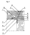
- the circumferential collar 2 also has a cylindrical overlap 7, which rests on the support ring 6 and secures the manhole cover attachment 1 against lateral displacement.
- the fixable support 5 has a bent annular element which forms a pressure chamber 10 as a flexible sealing lip system 14 between the circumferential collar 2 and the fit insert 3.
- four channels 8 are arranged on the circumference of the outer edge of the fitable insert 3, via which fluid pressure media, preferably water or compressed air, can be supplied to the pressure chamber 10 in order to release the fitable insert 3 from the construction of the circumferential collar 2 to effect.
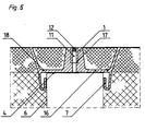
- a thermally stabilized and colored thermoplastic material made from recycling material was used for the construction of the manhole cover attachment 1.
- the manhole cover attachment 1 has a height which exceeds the difference between the existing upper edge of the manhole cover and the desired road surface by approximately 100 mm.
- the manhole cover attachment is shortened to the resulting differential dimension in the region of the circumferentially flared collar and the fit insert, in order then to be incorporated into the manufacture of the road surface when installed .
- the channels 8 for the supply of fluid pressure medium to the pressure chamber 10 have previously been closed with colored caps 12 in order to facilitate the position detection if necessary.
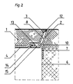
- the circumferential collar 2 has a circular shaped fixable support 5 and on the circumference distributes at least three pieces of overlaps 7 which rest on the support ring 6 and prevent the manhole cover attachment from moving sideways.
- This sealing lip system 14 includes a circular ring Pressure chamber 10, which in turn by at least two pieces on Circumferentially distributed channels 8 are supplied with pressure media can be.
- the channels 8 are in the circumferential collar 2 educated.
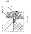
- a manhole cover attachment 1 consists of a circumferential collar 2 and a fitable insert 3.
- the circumferential collar 2 has, in addition to an annular overlap 7 resting on the support ring 6, a fixable support 5, which rests fully on the upper manhole cover 4.
- the annular overlap 7 is designed as a ring element 15 which is flared upwards and into which the downwardly conically tapered end of the fit insert 3 engages.
- This end together with the ring element 15 of the circumferential collar 2, forms the flexible sealing lip system 14, which, if necessary, includes a pressure chamber 10 receiving fluid pressure medium.
- a total of two channels 8 are incorporated, which are connected to the pressure chamber 10.
- the circumferential collar 2 is first positioned on the support ring 6, the elastic overlaps 7 positioning the circumferential collar 2 on the support ring 6.
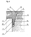
- the fit insert 3 then inserted into the circumferential collar 2 forms with its circular lower end an annular wedge which engages in the ring element 15 of the circumferential collar 2 and positions the manhole cover attachment 1 firmly at the upper edge of the manhole cover 4.
- the ring wedge of the fitable insert 3 is at the same time designed as a flexible sealing lip system 14, so that, if necessary, the introduction of fluid pressure media that supports the lifting of the fitable insert 3 can be made possible via the channels 8 formed in the fitable insert 3.
- the manhole cover attachment 1 is formed in one piece. He owns a bottom 16, the fixable support 5 on the upper edge of the Manhole cover 4 forms.
- the ring-shaped overlap 7 is flexibly designed and lies on the support ring 6. This ensures that the manhole cover 1 even with low dimensional accuracy Shaft construction sufficient against lateral displacement when Application of the road layers is secured.
- the necessary when exposing the top of the required Manhole cover 4 act as a predetermined breaking point 18.
- For the mechanical Removal from the traffic area has the manhole cover attachment 1 central bore 11, which is required for the tool holder 17th is formed and in which a colored and removable Cap 12 is inserted.
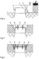
- FIGS. 6 to 12 there is a device for height compensation between the shaft cover and the road surface from an am Support ring 6 arranged up to the upper level of the binder layer reaching outer ring 19, which extends conically with about 3 ° upwards is executed.
- the outer ring 19 lies on the support ring by means of a cylindrical part bent at the top by friction.
- Both the outer ring 19 and the other parts of the device are made of thermoplastic.
- the inner surface of the sliding sliding ring 24 and the outer surface of the insert 25 are additionally coated with a material which improves the slidability.
- An attachment 20 is arranged on the manhole cover, the edge bent downward enclosing the manhole cover and at the same time covering the upwardly directed cylindrical part of the outer ring 19.
- the attachment 20 contains ventilation slots 21 which correspond in position to the ventilation slots of the manhole cover.
- sliding sleeves 22 are arranged, which are first inserted into the ventilation slots to such an extent that the upper edges of the sliding sleeves 22 are approximately at the level of the planned upper edge of the binder layer to be applied.
- a removable intermediate ring 23 with a V-shaped cross section is inserted into the outer ring 19 such that the upper edge of the removable intermediate ring 23 also extends to the intended height of the binder layer.
- this intermediate ring 23 is removed.
- the sliding sleeves 22 are pulled out of the ventilation slots 21 to such an extent that the upper edges of the sliding sleeves correspond to the intended position of the road surface.
- a sliding sliding ring 24 is inserted into the conical outer ring 19 and also aligned with its upper edge to the intended upper edge of the intended road surface.
- the insert 25 is inserted, which contains in its lower region an annular lower sealing lip 27 which bears on the outer ring 19 and furthermore contains an upper annular sealing lip 28 which bears on the attachment 20.
- the insert 25 here contains, for example, four pieces of fluid supply channels 8 which are uniformly distributed around the circumference of the insert 25 and by means of which, if necessary, pressurized fluid auxiliary media, for example compressed air or pressure fluid, can be introduced.
- pressurized fluid auxiliary media for example compressed air or pressure fluid
- web-shaped profiles 30 are also arranged, which serve the intimate connection of the cover layer material with the insert 25.
Landscapes
- Engineering & Computer Science (AREA)
- Environmental & Geological Engineering (AREA)
- Life Sciences & Earth Sciences (AREA)
- General Life Sciences & Earth Sciences (AREA)
- Mining & Mineral Resources (AREA)
- Paleontology (AREA)
- Civil Engineering (AREA)
- General Engineering & Computer Science (AREA)
- Structural Engineering (AREA)
- Underground Structures, Protecting, Testing And Restoring Foundations (AREA)
- Road Signs Or Road Markings (AREA)
Abstract
Description
Unzureichende Paßfähigkeit führt zwangsläufig zu vermeidbaren Belastungen der Fahrzeuge, der Verkehrsflächen und der Zugangsschächte gleichermaßen.
Deshalb sind Anstrengungen unverkennbar, mit Hilfe neuer technischer Mittel das bestehende Problem zuverlässig zu lösen.
So kennzeichnet die DE U1 297 07 603 die Schachtabdeckung von einer Kanalisation, bei der das oberste ringförmige Betonformteil des daraus hergestellten Schachtes eine obere Auflagefläche aufweist, auf der ein Tragrahmen für einen einlegbaren Schachtdeckel angeordnet ist und bei dem zumindest zwischen dem Tragrahmen und der Auflagefläche eine dauerelastische Auflage vorgesehen ist, die wenigstens aus einer organischen Reaktionsharzmasse mit stoßdämpfenden Eigenschaften besteht.
Die Anwendung dieser technischen Lösung verbessert zwar die Befahrbarkeit der Schachtabdeckung, erfordert jedoch nach wie vor entweder unterschiedlich dicke Tragrahmen und/oder maßlich präzise Gründungen der errichteten Schächte, wenn es nicht zu Höhendifferenzen zwischen der Oberfläche des elastisch verlagerten Schachtdeckels und der umgebenden Fahrbahnoberfläche kommen soll.
Mit Hilfe dieser technischen Lösung ist es prinzipiell möglich, die Schachtdeckelfüllung gemeinsam mit der übrigen Trag- und Verschleißschicht der umgebenden Verkehrsfläche herzustellen. Allerdings ist die erforderliche Paßfähigkeit zwischen der Oberkante der Deckelschale und der umgebenden Verkehrsfläche nur dadurch herzustellen, daß die Lagerung der Deckelschale bereits die erforderliche Maßhaltigkeit aufweist. Nachteilig an dieser Lösung ist außerdem, für die bedarfsweise Lösbarkeit des gefüllten Schachtdeckels bei erforderlichem Zugang zum Schacht besonders aufwendige Vorkehrungen treffen zu müssen.
Neben der stabilen und dauerhaften Einbindung der Schachtabdeckung in das umgebende Deckschichtenmaterial soll die wirtschaftliche Herstellbarkeit und die zuverlässige Vermeidung von Überfahrgeräuschen erreicht werden.
Die erforderlichen Anpassungsarbeiten lassen sich auf das Abschneiden des gegebenenfalls überstehenden Randes des umlaufenden Kragens und des paßfähigen Einsatzes auf das Niveau der Fahrbahnoberfläche reduzieren. Infolge der Möglichkeit des Einsatzes von fluiden Druckmitteln beim Lösen des paßfähigen Einsatzes aus dem umlaufenden Kragen läßt sich der Zugang zum jeweiligen Schacht im Bedarfsfall einfach und rationell gestalten. Sowohl nach dem Ausfüllen des paßfähigen Einsatzes mit Fahrbabnbelagmaterial als auch nach dem Wiedereinsetzen des zwischenzeitlich gelösten Schachtdeckeleinsatzes ist die mechanische und akustische Klapperfreiheit beim Überfahren gewährleistet. Erreicht wird außerdem eine höhere Sicherheit gegen das mißbräuchliche Entfernen der Schachtabdeckung wegen der dazu benötigten speziellen Arbeitsmittel. Die Überfahrbarkeit der Schachtabdeckung läßt sich aufdem vorgeschlagenen Wege ohne Inkaufnahme einer markanten Geräuschkulisse gewährleisten.
Als Vorteil der vorgeschlagenen technischen Lösung gilt weiterhin die Möglichkeit des Einsatzes von Recyclingbaustoffen für die Herstellung des Schachtdeckelaufsatzes, beispielsweise von mechanisch stabilisierten Altkunststoffen.
Dazu sind der Verschlußdeckel für die zentrale Bohrung und/oder die paßfähigen Wandungen von umlaufendem Kragen und paßfähigem Einsatz lagekennzeichnend farbgestaltet.
Das flexible Dichtlippensystem zwischen dem paßfähigen Einsatz und dem umlaufenden Kragen kann auch als Teil des umlaufenden Kragens ausgebildet sein.
Schließlichist ist es auchmöglich, das flexible Dichtlippensystem zwischen dem paßfähigen Einsatz und dem umlaufenden Kragen als Teil des paßfähigen Einsatzes auszubilden.
Der Schachtdeckelaufsatz weist dazu einen nach oben konisch erweiterten und mit Fahrbabnbelagsmaterial ausfüllbaren umlaufenden Kragen auf. Der umlaufende Kragen ist mit das seitliche Verschieben des Schachtdeckelaufsatzes verhindernden und am Auflagering anliegenden Übergriffen ausgestattet.
Außerdem ist der Schachtdeckelaufsatz mit einem aufdem Schachtdeckel aufliegenden Boden ausgestattet.
Am Boden des Schachtdeckelaufsatzes ist wenigstens eine bis zur Fahrbahnoberfläche reichende Werkzeugaufnahme angeordnet.
Bei Neubau oder bei Reparatur einer Fahrbahn wird am Auflagering unterhalb des Schachtdeckels ein bis in das Niveau der Binderschicht ragender Außenring angeordnet, der eine nach oben gerichtete konische Öffnung aufweist. Außerdem wird aufdem Schachtdeckel selbst ein Aufsatz mit Belüftungschlitzen angeordnet, wobei diese Belüftungsschlitze überwiegend mit den Öffnungen im Schachtdeckel übereinstimmen. In den Belüftungsschlitzen sind verschiebliche Schiebehülsen angeordnet, die zunächst beim Aufbringen von Binderschichtmaterial in eine entsprechend tiefere Stellung gebracht werden. Für das Auffüllen des Aufsatzes mit Binderschichtmateiial wird ein nach dem Auffüllen entnehmbarer Zwischenring zwischen dem Außenring und dem Aufsatz angeordnet, der nach seiner Entnahme zwischen dem Außenring und dem Binderschichimaterial oberhalb des Schachtdeckels einen nach oben konisch geöffneten Ringspalt bildet. Im konisch nach oben erweiterten Außenring wird nunmehr ein bis zur Sollhöhe der Deckschicht verschieblicher Schiebering angeordnet, in den ein Einsatz mit Fluidzuführungskanälen und oberen und unteren Dichtlippen eingebracht wird. In diesen Einsatz gelangt während des Aufbringens des Deckschichtmaterials auf die Fahrbahn das Deckschichtmaterial und bildet eine homogene Oberfläche, die lediglich von der Oberkante des Schiebrings, von der Oberkante des Einsatzes mit den verschließbaren Öffnungen der Fluidzuführungskanäle und von den Enden der in den Belüftungsschltzen angeordneten und bis zur oberen Ebene des Deckschichtmaterials reichenden Schiebehülsen unterbrochen wird. Im Reparaturfall können in die Schiebehülsen mechanische Hebehilfen eingesetzt werden, wobei der Schachtdeckel mit Aufbau nach annähernd 90° Drehung der mechanischen Hebehilfe abgehoben werden kann. Zur Erleichterung der Abnahme des Schachtdeckels vom Schachtbauwerk können in die Fluidzuführungskanäle beliebige fluide Medien eingebracht werden.
Weiterhin ist es möglich, an der Innenfläche des Einsatzes Profilierungen anzuordnen, die der innigen Verbindung des Deckschichtmaterials mit dem Einsatz dienen.
Zum erleichterten Einführen der mechanischen Hebehilfenkönnen die Belüftungsschlitze sowie die darin angeordneten Schiebhülsen mit einem ovalen oder einem rechteckigen Querschnitt ausgestattet sein. Diese Ausführungsform der Erfindung trägt im besonderen Maße der Forderung Rechnung, das Straßenbaumaterial zumindest formschlüssig auf dem oberen Abschluß des Schachtbauwerkes sicher zu fixieren, die innige Eingliederung der Vorrichtung zur Schachtabdeckung in den übrigen Teil des Fahrbahnaufbaus sicherzustellen und gleichzeitig zeit-, kosten- und kraftsparend die Zugänglichkeit des Schachtbauwerks im Reparatur- oder Inspektionsfall zu ermöglichen.
Der besondere Vorzug der erfindungsgemäßen technischen Lösung besteht darin, daß für die einzelnen Komponenten der Vorrichtung unterschiedliche Materialien, bevorzugt Bauteile aus recyclingfähigen Primär- oder Sekundärkunststoff, eingesetzt werden können. Derartige Teile lassen sich im Reparaturfall mit der Fahbahnoberfläche unproblematisch abfräsen.
In der beiliegenden Zeichnung zeigen:
- Fig. 1
- die schematische Schnittdarstellung der Kontaktstelle zwischen umlaufendem Kragen und paßfähigem Einsatz mit am umlaufenden Kragen angeordneter elastischer Dichtlippe, Druckkammer und Zuführungskanal für fluide Druckmittel im paßfähigen Einsatz;
- Fig. 2
- die schematische Schnittdarstellung vom umlaufendem Kragen mit daran angeordneter elastischer Dichtlippe, Abstützung und Druckkammer sowie angeordnetem Zuführungskanal für fluide Druckmittel;
- Fig. 3
- die schematische Schnittdarstellung der Kontaktstelle zwischen umlaufendem Kragen und paßfähigem Einsatz, wobei das fixierbare Auflager als Ringelement ausgebildet ist;
- Fig. 4
- die schematische Schnittdarstellung analog Fig. 3 mit einem bis zur Fahrbahnoberfläche reichenden umlaufenden Kragen und speziellem Dichtlippensystem am paßfähigem Einsatz;
- Fig. 5
- die schematische Schnittdarstellung eines einteiligen Schachtdeckelaufsatzes.
- Fig. 6
- die schematische Schnittdarstellung eines bis zum Auflagering freigelegten Schachtbauwerks mit am Auflagering angeordnetem Außenring;
- Fig. 7
- die schematische Schnittdarstellung eines freigelegten Schachthalses mit daran angeordnetem Außenring und auf dem Schachtdeckel aufgesetztem Aufsatz mit Belüftungsschlitzen und Schiebehülsen;
- Fig. 8
- die schematische Schnittdarstellung dermit Binderschichtmaterial ausgefüllten Teile der Vorrichtung unter Einsatz des zwischen Außenring und Aufsatz angeordnetem entnehmbaren Zwischenrings;
- Fig. 9
- die schematische Schnittdarstellung der Vorrichtung an einem Schachtbauwerk mit bis zur Fahrbahnoberfläche verschieblichen Schiebering;
- Fig. 10
- die schematische Schnittdarstellung der unter Anwendung eines Einsatzes mit Deckschichtmaterial fertiggestellten Fahrbahn im Bereich eines Schachtbauwerks;
- Fig. 11
- die schematische Schnittdarstellung der fertiggestellten Fahrbahn im Bereich einer Schachtabdeckung im Zustand des Abhebens der Vorrichtung mit Hilfe mechanischer Hebehilfen unter Zusatz von das Abheben unterstützenden fluiden Medien;
- Fig. 12
- den Ausschnitt einer schematischen Schnittdarstellung der Vorrichtung an einer Schachtabdeckung unter Einsatz von Außenring, Aufsatz mit Belüftungsschlitz und Schiebehülse (in zwei Ausführungsvarianten), Schiebering und Einsatz mit unteren und oberen Dichtlippen sowie Fluidzuführungkanälen.
Für die Konstruktion des Schachtdeckelaufsatzes 1 wurde ein thermisch stabilisierter und eingefärbter Thermoplastwerkstoff aus Recyclingmaterial verwendet. Im Rohbaumaß besitzt der Schachtdeckelaufsatz 1 eine solche Höhe, die um ca. 100 mm das Differenzmaß zwischen dem vorhandenen oberen Rand der Scbachtabdeckung und der gewünschten Fahrbahnoberfläche übersteigt.
Vor dem Aufbringen der Binder- und/oder Verschleißschichten aufdie die Schachtabdeckung umgebende Verkehrsfläche wird der Schachdeckelaufsatz im Bereich des konisch nach oben erweiterten umlaufenden Kragens und des paßfähigen Einsatzes aufdas sich ergebende Differenzmaß gekürzt, um danach im eingebauten Zustand in die Fertigung der Fahrbahnoberfläche einbezogen zu werden.
Die Kanäle 8 für das Zuführen von fluiden Druckmitteln zur Druckkammer 10 sind zuvor mit farbigen Verschlußdeckeln 12 verschlossen worden, um im Bedarfsfall die Lageerkennung zu erleichtern.
Der vollständig in den Fabrbahnaufbau integrierte Schachtdeckelaufsatz 1 stellt nunmehr für den rollenden Verkehr keine Inhomogenität mehr dar, führt zur Minderung von Geräuschsemissionen und verbessert die Standfestigkeit der Schachtkonstruktion und der umgebenden Verkehrsfläche.
In der Wandkonstruktion des paßfähigen Einsatzes 3 sind beispielsweise insgesamt zwei Kanäle 8 eingearbeitet, die mit der Druckkammer 10 in Verbindung stehen.
Der danach in denumlaufenden Kragen 2 eingesetzte paßfähige Einsatz 3 bildet mit seinem kreisringförmigen unteren Ende einen Ringkeil, der in das Ringelement 15 des umlaufenden Kragens 2 eingreift und den Schachtdeckelaufsatz 1 fest am oberen Rand der Schachtabdeckung 4 positioniert. Der Ringkeil des paßfähigen Einsatzes 3 ist gleichzeitig als flexibles Dichtlippensystem 14 ausgebildet, so daß bedarfsweise über die im paßfähigen Einsatz 3 ausgebildeten Kanäle 8 das, das Abheben des paßfähigen Einsatzes 3 unterstützende Einbringen von fluiden Druckmitteln ermöglicht werden kann.
Der Aufsatz 20 enthält Belüftungschlitze 21, die mit den Belüftungsschlitzen des Schachtdeckels lagemäßig übereinstimmen. In den Belüftungsschlitzen 21 sind Schiebehülsen 22 angeordnet, die zunächst soweit in die Belüftungsschlitze eingeschoben sind, daß sich die Oberkanten der Schiebehülsen 22 etwa in Höhe der geplanten Oberkante der aufzubringenden Binderschicht befinden. Danach wird in den Außenring 19 ein entnehmbarer Zwischenring 23 mit V-förmigen Querschnitt so eingelegt, daß die Oberkante des entnehmbaren Zwischenring 23 ebenfalls bis zur vorgesehenen Höhe der Binderschicht reicht. Nach Aufbringen der Binderschicht wird dieser Zwischenring 23 entnommen. Zugleich werden die Schiebehülsen 22 aus den Belüftungsschlitzen 21 soweit herausgezogen, daß die Oberkanten der Schiebehülsen der vorgesehenen Lage der Fahrbahnoberfläche entsprechen.
Danach wird in den konischen Außenring 19 ein verschieblicher Schiebering 24 eingesetzt und ebenfalls mit seiner Oberkante zur vorgesehenen Oberkante der vorgesehenen Fahrbahnoberfläche ausgerichtet. In diesen verschieblichen Schiebering 24 wird der Einsatz 25 eingelegt, der in seinem unteren Bereich eine ringförmige untere Dichtlippe 27 enthält, die am Außenring 19 anliegt, undweiterhin eine obere ringförmige Dichtlippe 28 enthält, die am Aufsatz 20 anliegt. Der Einsatz 25 enthält hier beispielsweise vier Stück am Umfang des Einsatzes 25 gleichverteilte Fluidzuführungskanäle 8, mit deren Hilfe bei Erfordernis unter Druck stehende fluide Hilfsmedien, beispielsweise Druckluft oder Druckflüssigkeit, eingebracht werden können.
Auf dem Aufsatz 20 sind beispielsweise nagelförmige Profilierungen 29 angeordnet, die dem innigen Verbund des Binderschichtmaterials mit dem Aufsatz 20 dienen.
An der Innenfläche des Einsatzes 25 sind ebenfalls stegförmige Profilierungen 30 angeordnet, die dem innigen Verbund des Deckschichtmaterials mit dem Einsatz 25 dienen.
- 1
- - Schachtdeckelaufsatz
- 2
- - umlaufender Kragen
- 3
- - paßfähiger Einsatz
- 4
- - oberer Rand der Schachtabdeckung
- 5
- - fixierbares Auflager
- 6
- - Auflagering
- 7
- - Übergriff
- 8
- - Kanal
- 9
- - paßfähige Wandung
- 10
- - Druckkammer
- 11
- - zentrale Bohrung
- 12
- - Verschlußdeckel
- 13
- - Abstützung
- 14
- - flexibles Dichtlippensystem
- 15
- - Ringelement
- 16
- - Boden des einteiligen Schachtdeckelaufsatzes
- 17
- - Werkzeugaufnahme
- 18
- - Sollbruchstelle
- 19
- - Außenring
- 20
- - Aufsatz
- 21
- - Belüftungsschlitz
- 22
- - verschiebliche Hülse
- 23
- - wiederverwendbarer Zwischenring
- 24
- - höhenverstellbarer Schiebering
- 25
- - Einsatz
- 26
- - mechanische Hebehilfe
- 27
- - untere Dichtlippen
- 28
- - obere Dichtlippe
- 29
- - Profilierung an der Oberseite des Aufsatzes
- 30
- - Profilierung an der Innenseite des Einsatzes
Claims (19)
- Vorrichtung zum Höhenausgleich zwischen Schachtabdeckung und Fahrbahnoberfläche als mit Fahrbahnbelagmaterial ausfüllbarer und homogen m die Fahrbahnoberfläche eingliederungsfähiger Schachtdeckelaufsatz, dadurch gekennzeichnet,daß der Schachtdeckelaufsatz (1) mehrteilig ausgebildet ist und wenigstens aus einem umlaufenden Kragen (2) und einem paßfähigen Einsatz (3) besteht,daß der umlaufende Kragen (2) aufdem oberen Rand der Scbachtabdeckung (4) fixierbare Auflager (5) aufweist,daß der umlaufende Kragen (2) das seitliche Verschieben verbindernde und am Auflagering (6) anliegende Übergriffe (7) aufweist,daß zwischen umlaufendem Kragen (2) und paßfähigem Einsatz (3) das Einführen von fluiden Druckmitteln zulassende Kanäle (8) angeordnet sind,daß die paßfähigen Wandungen (9) des umlaufenden Kragens (2) und des paßfähigen Einsatzes (3) nach oben konisch erweitert ausgebildet sind,daß die paßfähigen Wandungen (9) des umlaufenden Kragens (2) und des paßfähigen Einsatzes (3) thermisch odermechanisch kürzbar gestaltet sind unddaß zwischen paßfähigem Einsatz (3) und umlaufendem Kragen (2) mit fluiden Druckmitteln ausfüllbare Druckkammern (10) angeordnet sind.
- Vorrichtung nach dem Anspruch 1, dadurch gekennzeichnet, daß das fixierbare Auflager (5) als einteiliges und den gesamten Schachtabdeckung (4) zumindest teilweise überdeckendes Bauelement ausgebildet ist.
- Vorrichtung nach dem Anspruch 1, dadurch gekennzeichnet, daß das fixierbare Auflager (5) als mehrteiliges und den Schachtabdeckung (4) nur teilweise überdeckendes Bauelemet ausgebildet ist.
- Vorrichtung nach den Ansprüchen 1 bis 3, dadurch gekennzeichnet, daß der umlaufende Kragen (2) und der paßfähige Einsatz (3) aus einem einheitlichen Werkstoff, vorzugsweise aus gegen thermische Beanspruchung stabilisiertem Kunststoff, besteht.
- Vorrichtung nach den Ansprüchen 1 bis 4, dadurch gekennzeichnet, daß die Kanäle (8) und Druckkammern (10) für die Aufnahme von hydraulischen Druckmitteln ausgebildet sind.
- Vorrichtung nach einem der Ansprüche 1 bis 4, dadurch gekennzeichnet, daß die Kanäle (8) und Druckkammern (10) für die Aufnahme von pneumatischen Druckmittein ausgebildet sind.
- Vorrichtung nach einem der Ansprüche 1 bis 6, dadurch gekennzeichnet, daß der paßfähige Einsatz (3) eine zentrale Bohrung (11) für die Aufnahme von mechanischen Lösehilfen aufweist.
- Vorrichtung nach einem der Ansprüche 1 bis 7, dadurch gekennzeichnet, daß der Verschlußdeckel (12) für die zentrale Bohrung (11) und/oder die paßfähigen Wandungen (9) von umlaufendem Kragen (2) und paßfähigem Einsatz (3) lagekennzeichnend farbgestaltet sind.
- Vorrichtung nach einem der Ansprüche 1 bis 8, dadurch gekennzeichnet, daß die Abstützung (13) zwischen dem umlaufenden Kragen (2) und dem paßfähigen Einsatz (3) als druckkammerbildendes flexibles Dichtlippensystem (14) ausgebildet ist.
- Vorrichtung nach dem Anspruch 9, dadurch gekennzeichnet, daß das flexible Dichtlippensystem (14) zwischen dem paßfähigen Einsatz (3) und dem umlaufenden Kragen (2) als Teil des umlaufenden Kragens (2) ausgebildet ist.
- Vorrichtung nach dem Anspruch 9, dadurch gekennzeichnet, daß das flexible Dichtlippensystem (14) zwischen dem paßfähigen Einsatz (3) und dem umlaufenden Kragen (2) als Teil des paßfähigen Einsatzes (3) ausgebildet ist.
- Vorrichtung nach einem der Ansprüche 1 bis 11, dadurch gekennzeichnet, daß die das seitliche Verschieben des Schachtdeckelaufsatzes (1) verbindenden Übergriffe (7) als an dem Auflagering (6) anliegende und keilförmig aufweitbare Ringelemente (15) ausgebildet sind.
- Vorrichtung zum Höhenausgleich zwischen Schachtabdeckung und Fahrbahnoberfläche als mit Fahrbahnbelagmaterial ausfüllbarer und homogen in die Fahrbahnoberfläche eingliederungsfähiger Schachtdeckelaufsatz, dadurch gekennzeichnet,daß der Schachtdeckelaufsatz (1) einteilig ausgebildet ist,daß der Schachtdeckelaufsatz (1) einen nach oben konisch erweiterten undmit Fahrbahnbelagsmaterial ausfüllbaren umlaufenden Kragen (2) aufweist,daß der umlaufende Kragen (2) mit das seitliche Verschieben des Schachtdeckelaufsatzes (1) verhindernden und am Auflagering (6) anliegenden Übergriffen (7) ausgestattet ist,daß der Schachtdeckelaufsatz (1) mit einem auf dem Schachtdeckel aufliegenden Boden (16) ausgestattet ist,daß an dem Boden (16) des Schachtdeckelaufsatzes (1) wenigstens eine bis zur Fahrbahnoberfläche reichende Werkzeugaufnahme (17) angeordnet ist unddaß im Boden (16) außerhalb des Bereichs des Schachtdeckels wenigstens eine als Sollbruchstelle (18) ausgebildete Zone angeordnet ist.
- Vorrichtung zum Höhenausgleich zwischen Schachtabdeckung und Fahrbahnoberfläche als mit Fahrbahnbelagmaterial ausfüllbarer und homogen in die Fahrbahnoberfläche eingliederungsfähiger Schachtdeckelaufsatz, dadurch gekennzeichnet,daß die Vorrichtung zum Höhenausgleich mehrteilig ausgebildet ist,daß ein bis in das Niveau der Binderschicht ragender Außenring (19) am Auflagering (6) mit nach oben geöffneter Konizität angeordnet ist,daß auf dem Schachtdeckel ein Aufsatz (20) mit Belüftungsschlitzen (21) und Schiebehülsen (22) angeordnet ist,daß ein beim Auffüllen des Aufsatzes (20) mit Binderschichtmaterial der Bildung eines nach oben geöffneten konischen Ringspaltes dienender und nach dem Auffüllen entnehmbarer Zwichenring (23) zwischen dem Außenring (19) und dem Aufsatz (20) angeordnet ist,daß im konischen Außenring (19) ein bis zur Sollhöhe der Deckschicht verschieblicher Schiebering (24) angeordnet ist unddaß ein der Aufnahme von Deckschichtmaterial dienender und in den Schiebering (24) einbringbarer Einsatz (25) mit den Fluidzuführungskanälen (8) und den oberen und unteren Dichtlippen (27, 28) angeordnet ist.
- Vorrichtung nach dem Anspruch 14, dadurch gekennzeichnet, daß in die Schiebehülsen (22) einführbare und nach annähernd 90° Drehung zum Abheben des Schachtdeckels dienende mechanische Hebebilfen (26) anordnungsfähig sind.
- Vorrichtung nach einem der Ansprüche 14 und 15, dadurch gekennzeichnet, daß am Aufsatz (20) der innigen Verbindung des einzubringenden Binderschichtmaterials mit dem Aufsatz (20) dienende Profilierungen (29) angeordnet sind.
- Vorrichtung nach einem der Ansprüche 14 bis 16, dadurch gekennzeichnet, daß an der Innenfläche des Einsatzes (25) der innigen Verbindung des Deckschichtmaterials mit dem Einsatz (25) dienende Profilierungen (30) angeordnet sind.
- Vorrichtung nach einem der Ansprüche 14 bis 17, dadurch gekennzeichnet, daß die Belüftungsschlitze (21) und die Schiebehülsen (22) mit einem ovalen Querschnitt ausgestattet sind.
- Vorrichtung nach einem der Ansprüche 14 bis 17, dadurch gekennzeichnet, daß die Belüftungsschlitze (21) und die Schiebehülsen (22) mit einem rechteckigen Querschnitt ausgestattet sind.
Applications Claiming Priority (2)
| Application Number | Priority Date | Filing Date | Title |
|---|---|---|---|
| DE19819334 | 1998-04-30 | ||
| DE19819334 | 1998-04-30 |
Publications (3)
| Publication Number | Publication Date |
|---|---|
| EP0953687A2 true EP0953687A2 (de) | 1999-11-03 |
| EP0953687A3 EP0953687A3 (de) | 2000-01-05 |
| EP0953687B1 EP0953687B1 (de) | 2006-08-16 |
Family
ID=7866291
Family Applications (1)
| Application Number | Title | Priority Date | Filing Date |
|---|---|---|---|
| EP99108212A Expired - Lifetime EP0953687B1 (de) | 1998-04-30 | 1999-04-27 | Vorrichtung zum Höhenausgleich zwischen Schachthals und Fahrbahnoberfläche und Anordnung der Vorrichtung in einer Fahrbahnkonstruktion |
Country Status (3)
| Country | Link |
|---|---|
| EP (1) | EP0953687B1 (de) |
| AT (1) | ATE336620T1 (de) |
| DE (2) | DE59913773D1 (de) |
Cited By (5)
| Publication number | Priority date | Publication date | Assignee | Title |
|---|---|---|---|---|
| SG87147A1 (en) * | 2000-08-01 | 2002-03-19 | Byung Moo Ahn | Steel manhole |
| AU2003203540B2 (en) * | 2002-05-30 | 2007-05-31 | Bullock Mfg Pty Limited | An Access Panel |
| DE10329695B4 (de) * | 2003-07-02 | 2010-05-12 | Schädler, Reiner | Schacht mit höhenverstellbarer Schachtabdeckung |
| EP3556944A1 (de) * | 2018-04-18 | 2019-10-23 | MeierGuss Sales & Logistics GmbH & Co. KG | Schachtabdeckungsrahmen, schachtabdeckungsanordnung, schachtanordnung und installationsverfahren |
| US11326321B2 (en) | 2020-02-28 | 2022-05-10 | Barrco, Inc. | Height-adjustable fixtures for buried tubulars and methods of adjusting the height-adjustable fixtures |
Families Citing this family (1)
| Publication number | Priority date | Publication date | Assignee | Title |
|---|---|---|---|---|
| AT14954U1 (de) * | 2015-09-24 | 2016-09-15 | Aco Severin Ahlmann Gmbh & Co Kg | Entwässerungsvorrichtung zur Ableitung von Abwasser |
Citations (3)
| Publication number | Priority date | Publication date | Assignee | Title |
|---|---|---|---|---|
| DE9401426U1 (de) | 1994-01-28 | 1994-03-24 | Passavant-Werke Ag, 65326 Aarbergen | Mit Beton gefüllter Schachtdeckel für befahrbare Schachtabdeckungen |
| DE4332968C2 (de) | 1993-09-28 | 1997-06-05 | Buderus Guss Gmbh | Runder Schachtdeckel |
| DE29707603U1 (de) | 1997-04-26 | 1997-07-03 | DENSO-Holding GmbH & Co., 51371 Leverkusen | Schachtabdeckung an einer Kanalisation |
Family Cites Families (5)
| Publication number | Priority date | Publication date | Assignee | Title |
|---|---|---|---|---|
| CH369075A (de) * | 1959-03-04 | 1963-04-30 | Von Roll Ag | Bodenwasserablauf |
| GB1186860A (en) * | 1968-01-04 | 1970-04-08 | Dover Eng Works Ltd | Improvements relating to manhole and like covers and frames |
| DE7331952U (de) * | 1973-09-03 | 1973-12-13 | Passavant-Werke Michelbacher Huette | Schachtabdeckung |
| DE3920327A1 (de) * | 1989-06-21 | 1991-01-10 | Ernst Zuern Unternehmen Fuer I | Hoehenverstellbare strassenkappe |
| JPH07331685A (ja) * | 1994-06-06 | 1995-12-19 | Daiichi Kizai Kk | 単目地充填式化粧マンホールカバー |
-
1999
- 1999-04-27 DE DE59913773T patent/DE59913773D1/de not_active Expired - Fee Related
- 1999-04-27 DE DE19918944A patent/DE19918944A1/de not_active Withdrawn
- 1999-04-27 EP EP99108212A patent/EP0953687B1/de not_active Expired - Lifetime
- 1999-04-27 AT AT99108212T patent/ATE336620T1/de not_active IP Right Cessation
Patent Citations (3)
| Publication number | Priority date | Publication date | Assignee | Title |
|---|---|---|---|---|
| DE4332968C2 (de) | 1993-09-28 | 1997-06-05 | Buderus Guss Gmbh | Runder Schachtdeckel |
| DE9401426U1 (de) | 1994-01-28 | 1994-03-24 | Passavant-Werke Ag, 65326 Aarbergen | Mit Beton gefüllter Schachtdeckel für befahrbare Schachtabdeckungen |
| DE29707603U1 (de) | 1997-04-26 | 1997-07-03 | DENSO-Holding GmbH & Co., 51371 Leverkusen | Schachtabdeckung an einer Kanalisation |
Cited By (6)
| Publication number | Priority date | Publication date | Assignee | Title |
|---|---|---|---|---|
| SG87147A1 (en) * | 2000-08-01 | 2002-03-19 | Byung Moo Ahn | Steel manhole |
| AU2003203540B2 (en) * | 2002-05-30 | 2007-05-31 | Bullock Mfg Pty Limited | An Access Panel |
| DE10329695B4 (de) * | 2003-07-02 | 2010-05-12 | Schädler, Reiner | Schacht mit höhenverstellbarer Schachtabdeckung |
| EP3556944A1 (de) * | 2018-04-18 | 2019-10-23 | MeierGuss Sales & Logistics GmbH & Co. KG | Schachtabdeckungsrahmen, schachtabdeckungsanordnung, schachtanordnung und installationsverfahren |
| DE202019005915U1 (de) | 2018-04-18 | 2023-04-05 | Meierguss Sales & Logistics Gmbh & Co. Kg | Schachtabdeckungsrahmen, Schachtabdeckungsanordnung und Schachtanordnung |
| US11326321B2 (en) | 2020-02-28 | 2022-05-10 | Barrco, Inc. | Height-adjustable fixtures for buried tubulars and methods of adjusting the height-adjustable fixtures |
Also Published As
| Publication number | Publication date |
|---|---|
| EP0953687B1 (de) | 2006-08-16 |
| ATE336620T1 (de) | 2006-09-15 |
| EP0953687A3 (de) | 2000-01-05 |
| DE59913773D1 (de) | 2006-09-28 |
| DE19918944A1 (de) | 2000-01-20 |
Similar Documents
| Publication | Publication Date | Title |
|---|---|---|
| EP0953687B1 (de) | Vorrichtung zum Höhenausgleich zwischen Schachthals und Fahrbahnoberfläche und Anordnung der Vorrichtung in einer Fahrbahnkonstruktion | |
| EP2381037A1 (de) | Selbstnivellierender Schachtabdeckungsrahmen | |
| DE2241222C3 (de) | Höhenverstellbarer Deckelrahmen für einen Straßenschacht o.dgl. | |
| DE29924904U1 (de) | Vorrichtung zum Höhenausgleich zwischen Schachtabdeckung und Fahrbahnoberfläche | |
| DE69333069T2 (de) | In höhe und azimut verstellbarer behälter | |
| DE202008000463U1 (de) | Schieberkappe für den Straßeneinbau | |
| EP1031663A2 (de) | Vorrichtung zum Abdecken von Schächten sowie Trennvorrichtung zum Freilegen von Schachtabdeckungen | |
| EP0120218B1 (de) | Strassenkappe für Schieber von unter Flur verlegten Leitungen | |
| DE19738218C2 (de) | Tragrahmen für Kanalabdeckungen, Steigleitungsanordnung und Verfahren zur Herstellung | |
| DE10009871C2 (de) | Kappenvorrichtung zum Einbau in Fahrbahnen oder/und Gehwegen | |
| EP1048787A2 (de) | Verfahren und Vorrichtung zur Reperatur oder zum Ersetzen von Teilen einer bituminösen Strassendecke | |
| EP2319993B1 (de) | Führung | |
| DE3821545A1 (de) | Schachtabdeckung fuer in verkehrsflaechen liegende schaechte | |
| EP4283041B1 (de) | Rampe für ein plattenelement | |
| DE10056130C2 (de) | Schachtabdeckung und Verfahren zur Vorbereitung einer Schachtabdeckung | |
| DE2000966C3 (de) | Fahrbahnbelag aus Betonplatten | |
| DE4413062C2 (de) | Straßeneinlauf | |
| DE2030276C3 (de) | Schachtabdeckung, bestehend aus einem Deckel und einem in der Höhe verstellbaren Rahmen | |
| DE19641473C1 (de) | Verfahren und Vorrichtung zum Ausgleichen einer Absenkung einer Schachtabdeckung | |
| AT409643B (de) | Höhen- und neigungsjustierbare kanalschachtabdeckung | |
| AT408105B (de) | Strassenkappe | |
| DE102024113052A1 (de) | Straßenkappe | |
| EP0950766A1 (de) | Ausgleichringe für Schachtabdeckungen und Strasseneinläufe | |
| DE102010047728A1 (de) | Verfahren zum Herstellen und Anordnung eines Revisionsschachtes eines Kanals in einer Straße | |
| DE102004017805A1 (de) | Schachtabdeckung |
Legal Events
| Date | Code | Title | Description |
|---|---|---|---|
| PUAI | Public reference made under article 153(3) epc to a published international application that has entered the european phase |
Free format text: ORIGINAL CODE: 0009012 |
|
| AK | Designated contracting states |
Kind code of ref document: A2 Designated state(s): AT BE DE ES FR GB IT NL SE |
|
| AX | Request for extension of the european patent |
Free format text: AL;LT;LV;MK;RO;SI |
|
| PUAL | Search report despatched |
Free format text: ORIGINAL CODE: 0009013 |
|
| AK | Designated contracting states |
Kind code of ref document: A3 Designated state(s): AT BE CH CY DE DK ES FI FR GB GR IE IT LI LU MC NL PT SE |
|
| AX | Request for extension of the european patent |
Free format text: AL;LT;LV;MK;RO;SI |
|
| RIC1 | Information provided on ipc code assigned before grant |
Free format text: 7E 02D 29/14 A, 7B 66F 19/00 B |
|
| 17P | Request for examination filed |
Effective date: 20000606 |
|
| AKX | Designation fees paid |
Free format text: AT BE DE ES FR GB IT NL SE |
|
| 17Q | First examination report despatched |
Effective date: 20031008 |
|
| GRAP | Despatch of communication of intention to grant a patent |
Free format text: ORIGINAL CODE: EPIDOSNIGR1 |
|
| RTI1 | Title (correction) |
Free format text: HEIGHT LEVELLING DEVICE BETWEEN A MANHOLE COLLAR AND A ROADWAY SURFACE AND IMPLEMENTATION OF THE DEVICE IN A ROADWAY CONSTRUCTION |
|
| GRAS | Grant fee paid |
Free format text: ORIGINAL CODE: EPIDOSNIGR3 |
|
| GRAA | (expected) grant |
Free format text: ORIGINAL CODE: 0009210 |
|
| AK | Designated contracting states |
Kind code of ref document: B1 Designated state(s): AT BE DE ES FR GB IT NL SE |
|
| PG25 | Lapsed in a contracting state [announced via postgrant information from national office to epo] |
Ref country code: NL Free format text: LAPSE BECAUSE OF FAILURE TO SUBMIT A TRANSLATION OF THE DESCRIPTION OR TO PAY THE FEE WITHIN THE PRESCRIBED TIME-LIMIT Effective date: 20060816 Ref country code: IT Free format text: LAPSE BECAUSE OF FAILURE TO SUBMIT A TRANSLATION OF THE DESCRIPTION OR TO PAY THE FEE WITHIN THE PRESCRIBED TIME-LIMIT;WARNING: LAPSES OF ITALIAN PATENTS WITH EFFECTIVE DATE BEFORE 2007 MAY HAVE OCCURRED AT ANY TIME BEFORE 2007. THE CORRECT EFFECTIVE DATE MAY BE DIFFERENT FROM THE ONE RECORDED. Effective date: 20060816 Ref country code: GB Free format text: LAPSE BECAUSE OF FAILURE TO SUBMIT A TRANSLATION OF THE DESCRIPTION OR TO PAY THE FEE WITHIN THE PRESCRIBED TIME-LIMIT Effective date: 20060816 |
|
| REG | Reference to a national code |
Ref country code: GB Ref legal event code: FG4D Free format text: NOT ENGLISH |
|
| REF | Corresponds to: |
Ref document number: 59913773 Country of ref document: DE Date of ref document: 20060928 Kind code of ref document: P |
|
| PG25 | Lapsed in a contracting state [announced via postgrant information from national office to epo] |
Ref country code: SE Free format text: LAPSE BECAUSE OF FAILURE TO SUBMIT A TRANSLATION OF THE DESCRIPTION OR TO PAY THE FEE WITHIN THE PRESCRIBED TIME-LIMIT Effective date: 20061116 |
|
| PG25 | Lapsed in a contracting state [announced via postgrant information from national office to epo] |
Ref country code: ES Free format text: LAPSE BECAUSE OF FAILURE TO SUBMIT A TRANSLATION OF THE DESCRIPTION OR TO PAY THE FEE WITHIN THE PRESCRIBED TIME-LIMIT Effective date: 20061127 |
|
| NLV1 | Nl: lapsed or annulled due to failure to fulfill the requirements of art. 29p and 29m of the patents act | ||
| GBV | Gb: ep patent (uk) treated as always having been void in accordance with gb section 77(7)/1977 [no translation filed] |
Effective date: 20060816 |
|
| EN | Fr: translation not filed | ||
| PLBE | No opposition filed within time limit |
Free format text: ORIGINAL CODE: 0009261 |
|
| STAA | Information on the status of an ep patent application or granted ep patent |
Free format text: STATUS: NO OPPOSITION FILED WITHIN TIME LIMIT |
|
| 26N | No opposition filed |
Effective date: 20070518 |
|
| BERE | Be: lapsed |
Owner name: SCHONE, GERHARD Effective date: 20070430 |
|
| PG25 | Lapsed in a contracting state [announced via postgrant information from national office to epo] |
Ref country code: BE Free format text: LAPSE BECAUSE OF NON-PAYMENT OF DUE FEES Effective date: 20070430 |
|
| PG25 | Lapsed in a contracting state [announced via postgrant information from national office to epo] |
Ref country code: FR Free format text: LAPSE BECAUSE OF FAILURE TO SUBMIT A TRANSLATION OF THE DESCRIPTION OR TO PAY THE FEE WITHIN THE PRESCRIBED TIME-LIMIT Effective date: 20070511 |
|
| PG25 | Lapsed in a contracting state [announced via postgrant information from national office to epo] |
Ref country code: FR Free format text: LAPSE BECAUSE OF FAILURE TO SUBMIT A TRANSLATION OF THE DESCRIPTION OR TO PAY THE FEE WITHIN THE PRESCRIBED TIME-LIMIT Effective date: 20060816 |
|
| PGFP | Annual fee paid to national office [announced via postgrant information from national office to epo] |
Ref country code: DE Payment date: 20090415 Year of fee payment: 11 Ref country code: AT Payment date: 20090414 Year of fee payment: 11 |
|
| PG25 | Lapsed in a contracting state [announced via postgrant information from national office to epo] |
Ref country code: AT Free format text: LAPSE BECAUSE OF NON-PAYMENT OF DUE FEES Effective date: 20100427 |
|
| PG25 | Lapsed in a contracting state [announced via postgrant information from national office to epo] |
Ref country code: DE Free format text: LAPSE BECAUSE OF NON-PAYMENT OF DUE FEES Effective date: 20101103 |