EP0931662B1 - Ink-jet printer and method of controlling the same - Google Patents
Ink-jet printer and method of controlling the same Download PDFInfo
- Publication number
- EP0931662B1 EP0931662B1 EP99300465A EP99300465A EP0931662B1 EP 0931662 B1 EP0931662 B1 EP 0931662B1 EP 99300465 A EP99300465 A EP 99300465A EP 99300465 A EP99300465 A EP 99300465A EP 0931662 B1 EP0931662 B1 EP 0931662B1
- Authority
- EP
- European Patent Office
- Prior art keywords
- ink
- print head
- jet printer
- pump
- tank
- Prior art date
- Legal status (The legal status is an assumption and is not a legal conclusion. Google has not performed a legal analysis and makes no representation as to the accuracy of the status listed.)
- Expired - Lifetime
Links
Images


Classifications
-
- B—PERFORMING OPERATIONS; TRANSPORTING
- B41—PRINTING; LINING MACHINES; TYPEWRITERS; STAMPS
- B41J—TYPEWRITERS; SELECTIVE PRINTING MECHANISMS, i.e. MECHANISMS PRINTING OTHERWISE THAN FROM A FORME; CORRECTION OF TYPOGRAPHICAL ERRORS
- B41J2/00—Typewriters or selective printing mechanisms characterised by the printing or marking process for which they are designed
- B41J2/005—Typewriters or selective printing mechanisms characterised by the printing or marking process for which they are designed characterised by bringing liquid or particles selectively into contact with a printing material
- B41J2/01—Ink jet
- B41J2/17—Ink jet characterised by ink handling
- B41J2/18—Ink recirculation systems
-
- B—PERFORMING OPERATIONS; TRANSPORTING
- B41—PRINTING; LINING MACHINES; TYPEWRITERS; STAMPS
- B41J—TYPEWRITERS; SELECTIVE PRINTING MECHANISMS, i.e. MECHANISMS PRINTING OTHERWISE THAN FROM A FORME; CORRECTION OF TYPOGRAPHICAL ERRORS
- B41J2/00—Typewriters or selective printing mechanisms characterised by the printing or marking process for which they are designed
- B41J2/005—Typewriters or selective printing mechanisms characterised by the printing or marking process for which they are designed characterised by bringing liquid or particles selectively into contact with a printing material
- B41J2/01—Ink jet
- B41J2/17—Ink jet characterised by ink handling
- B41J2/1707—Conditioning of the inside of ink supply circuits, e.g. flushing during start-up or shut-down
-
- B—PERFORMING OPERATIONS; TRANSPORTING
- B41—PRINTING; LINING MACHINES; TYPEWRITERS; STAMPS
- B41J—TYPEWRITERS; SELECTIVE PRINTING MECHANISMS, i.e. MECHANISMS PRINTING OTHERWISE THAN FROM A FORME; CORRECTION OF TYPOGRAPHICAL ERRORS
- B41J2/00—Typewriters or selective printing mechanisms characterised by the printing or marking process for which they are designed
- B41J2/005—Typewriters or selective printing mechanisms characterised by the printing or marking process for which they are designed characterised by bringing liquid or particles selectively into contact with a printing material
- B41J2/01—Ink jet
- B41J2/17—Ink jet characterised by ink handling
- B41J2/175—Ink supply systems ; Circuit parts therefor
-
- B—PERFORMING OPERATIONS; TRANSPORTING
- B41—PRINTING; LINING MACHINES; TYPEWRITERS; STAMPS
- B41J—TYPEWRITERS; SELECTIVE PRINTING MECHANISMS, i.e. MECHANISMS PRINTING OTHERWISE THAN FROM A FORME; CORRECTION OF TYPOGRAPHICAL ERRORS
- B41J2202/00—Embodiments of or processes related to ink-jet or thermal heads
- B41J2202/01—Embodiments of or processes related to ink-jet heads
- B41J2202/12—Embodiments of or processes related to ink-jet heads with ink circulating through the whole print head
Definitions
- the present invention relates to an ink-jet printer which prints an image onto a print medium held on a rotary drum with ink jetted from a print head, and particularly, to an ink-jet printer in which ink is supplied from an ink tank apart from the print head.
- serial-type ink-jet printers are widely spreading.
- a print head and an ink tank of a relatively small capacity are mounted on a carriage and the carriage is movably attached to a guide bar extending across a paper sheet to be printed.
- the paper sheet is fed in a direction perpendicular to the guide bar at a constant pitch, and the carriage is moved along the guide bar each time paper sheet is fed by the pitch.
- a serial-type color ink-jet printer a plurality of print heads are employed and are supplied with ink of different colors from the respective ink tanks. The plurality of print heads are beforehand filled with ink when the printer is shipped. In the structure as described above, a color image of A4 size is printed out at a relatively low speed.
- This ink-jet printer includes a rotary drum rotating in one direction and a print head disposed to face a paper sheet held on the rotary drum.
- the print head has a plurality of line-type nozzle units which are arranged along the peripheral surface of the rotary drum, corresponding to cyan(C), yellow(Y), magenta(M) and black(B).
- Each nozzle unit has a plurality of ink-jet nozzles disposed across the paper sheet in the axial direction of the rotary drum.
- This ink-jet printer jets ink droplets from nozzle units in response to image signals to print a color image on the paper sheet rotating together with the rotary drum.
- a color image of A4 size can be printed extremely faster than the above-described serial-type printers.
- a plurality of ink tanks are placed apart from the print head and store ink of different colors to be supplied to the nozzle units of the print head.
- Each ink tank is connected to a corresponding nozzle unit via a supply tube, and is filled with ink supplied from an ink supplement bottle detachably attached thereto.
- the ink is conveyed from the ink tank to an ink pressure chamber of the nozzle unit by a supply pump having a valve function and interposed in the supply tube.
- the supply pump is stopped in a valve-open state, and the nozzle unit is driven to jet ink.
- ink is supplemented to the ink pressure chamber through the supply tube by a capillary action.
- the nozzle unit is empty when the printer is shipped and is filled with ink at a user side when the printer is used.
- Foreign matter such as a lump of dried ink may exist in the nozzle unit at the beginning of ink-supply.
- ink-jet nozzles of the nozzle unit are apt to be clogged by the foreign matter and the quality of printing carried out by such a nozzle unit deteriorates.
- GB 1562878 discloses an ink jet printer having the precharacterising features of claim 1.
- An object of the present invention is to carry out a high quality printing on a print medium by an inkjet printer.
- the invention seeks to reduce or prevent the entrance of lumps of dried ink into a plurality of ink-jet nozzles of an ink-jet printer.
- the invention also seeks to provide an ink-jet printer having a novel ink supply stem.
- an ink-jet printer as claimed in claim 1.
- FIGS.1 to 6 An ink-jet printer according to an embodiment of the present invention is described with reference to FIGS.1 to 6.
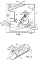
- FIG. 1 shows the internal structure of the ink-jet printer
- the ink-jet printer is used to perform a multicolor printing on a paper sheet P cut as n printing medium.
- the paper sheet P may be a plain paper, a coated paper or an OIII' sheet.
- the ink-jet printer comprises a rotary drum 10, a print head 20U. a manual-feed tray T1, a paper cassette T2. a sheet feed-in mechanism FM1, a sheet feed-out mechanism FM2, an ink supply system SP and a control unit. CNT.
- the rotary drum 10 rotates at a predetermined circumferential speed, with a paper sheet P held thereon.
- the print head 20U performs a multicolor printing on the paper sheet P.
- the manual-feed tray T1 places thereon paper sheets P for feeding one by one.
- the paper cassette T2 stores therein a stack of paper sheets I'.
- the sheet feed-in mechansim FMI feeds each paper sheet P from the paper cassette T2 or the manual-feed tray T1 onto the rotary drum 10.
- the sheet feed-out mechanism FM2 feeds out the paper sheet P printed at the rotary drum 10.
- the ink supply system SP performs an ink supply.
- the control unit CNT controls the overall operation made by the components or circuits of the ink jet printer.
- the control unit is construed as a controller.
- the rotary drum 10 is located near the central position within a housing 1.
- the manual-feed tray T1 is located below the rotary drum 10 and extends externally from a side wall face of the housing 1, and the paper cassette T2 is located under the rotary drum 10.
- the sheet feed-in mechanism FM 1 is placed upstream of the rotary drum 10.
- the print head 20U is located above the rotary drum 10.
- the sheet feed-out mechanism FM2 is located downstream of the rotary drum 10.
- the rotary drum 10 is supported about the axis Z, and causes the paper sheet P to be wound around a peripheral surface 11 thereof in accordance with its rotation indicated by an arrow R in FIG2.
- the rotational position of the rotary drum 10 is detected by a rotational position detector DT disposed near the peripheral surface 11 of the rotary drum 10.
- the print head 20U includes four nozzle units 20 (C, Y, M, and B) which are arranged in order along the peripheral surface 11 of the rotary drum 10 from the upstream side to the downstream side so as to perform a printing on the paper sheet P with inks of cyan(C), yellow(Y), magenta(M), and black(B).
- the nozzle units 20 receive ink of corresponding colors from the ink supply system SP.
- Each of the nozzle units 20 has a plurality of ink-jet nozzles 23 which are arranged in the axial direction X of the rotary drum 10 to have a span corresponding to the width of the paper sheet P of A4 size and jet the corresponding color ink to the paper sheet P.
- the plurality of ink-jet nozzles 23 are provided with heaters acting as an energy generator and thus, ink is jetted from nozzles 23 when heaters are selectively energized in a print mode. Piezo-electric element may be used, instead of the heater, to jet ink.
- the nozzle units 20 are constructed in structures identical to each other.
- Each of the nozzle units 20 (C, Y, M, and B) has four nozzle segments 20A to 20D arrayed in a zigzag form on a connection plate (not shown) extending in the axial direction X of the rotary drum 10.
- the nozzle segments 20A and 20C are mounted on a first surface of the connection plate, and the nozzle segments 20B and 20D are mounted on a second surface of connection plate opposed to the first surface, for example.
- each of the nozzle segments 20A to 20D is constituted by ink-jet nozzles 23 and an ink pressure chamber 22 for directly applying ink to the ink-jet nozzles 23.
- the ink pressure chambers 22 of the nozzle segments 20A to 20D are connected in series such that ink flows there-through as shown in FIG.3.
- Each of the ink pressure chambers 22 has a capacity of 0.55 ml.
- the pitch of the ink-jet nozzles 23 is set up to 1/150 inch, for example, in the case where the printing resolution is 300 dpi in the main scanning direction X.
- the sheet feed-in mechanism FM1 has a sheet loader LD for loading the paper sheet P to the rotary drum 10 such that the width direction of the paper sheet P corresponds with the axial direction X of the rotary drum 10.
- the paper sheet P is taken out of either the manual feed tray T1 or the paper cassette T2 by the sheet feed-in mechanism FM1.
- the paper loader LD is controlled to load the paper sheet P toward the rotary drum 10 when the position detector DT detects the rotary drum 10 at a predetermined rotating position.
- the paper sheet P is then wound around the peripheral surfacell of the rotary drum 10 when the rotary drum 10 made one rotation.
- the print head 20U prints a color image on the paper sheet P as the rotary drum 10 rotates.
- the paper loader LD includes at least a pair of loading rollers R1 and R2 extending in the axial direction X of the rotary drum 10 to load the paper sheet P fed from the manual-feed tray T1 or paper cassette T2 to the rotary drum 10 at a predetermined timing.
- the feeding speed of the paper of the paper sheet P is set at a speed corresponding to the circumferential speed of the rotary drum 10.
- the peripheral surface 11 of the rotary drum 10 is about 220 mm wide in the axial direction X and 408 mm long in the rotational direction R. Therefore, the rotary drum 10 can fully hold the A4 size paper sheet P having a width of 210 mm and a length of 297 mm.
- the paper sheet P is removed from the peripheral surface 11 of the rotary drum 10 by a sheet separator PL and fed in a predetermined direction by the sheet feed-out mechanism FM2.
- Driving of the sheet feed-in mechanism FM1 and the sheet feed-out mechanism FM2 are performed by a sheet feed motor FM.
- the paper separator PL includes a separation claw to be contacted with the peripheral surface 11 of the rotary drum 10 at the time of sheet removal.
- a discharge switch SEL guides the paper sheet P to either a rear discharge tray RT or an upper discharge tray UT.
- the rear discharge tray RT receives the paper sheet P with the print surface facing upward
- the upper discharge tray UT receives the paper sheet P with the print surface facing downward.
- the print head 20U is capable of being reciprocally shifted by 1/75 inch in the main scanning direction parallel to the axial direction X of the rotary drum 10.
- the rotary drum 10 holds the paper sheet P, and rotates in a sub-scanning direction perpendicular to the main scanning direction X.
- the rotary drum 10 is maintained at a constant rotation rate of 120 rpm and makes one rotation every 0.5 second, for example.
- the print head 20U is shifted in the main scanning direction X at a constant rate of 1/2 nozzle pitch each time the rotary drum 10 makes one rotation, so that it move for a distance equal to a nozzle pitch PT while the rotary drum 10 makes two rotations.
- the ink-jet printer further includes an elevation mechanism 90 for automatically adjusting the height of the print head 20U, an ink collection tray 30 for collecting ink flowed out of the print head 20U during a non-printing time, and a reciprocating rotation mechanism 46 for rotating reciprocally the ink collection tray 30 along the peripheral surface 11 of the rotary drum 10 such that the ink collection tray 30 can face the print head 20U.
- the elevation mechanism 90 moves the print head 20U to a lower limit position (print position) near the peripheral surface 11 of the rotary drum 10.
- the elevation mechanism 90 moves the print head 20U to an upper limit position spaced from the rotary drum 10, and then to a non-print position wherein print head 20U is located between the upper and lower limit positions.
- the elevation mechanism 90 sets the print head 20U in a state where the print head 20U is disposed at the upper limit position at the non-printing time, so that the ink collection tray 30 is inserted between the print head 20U and the rotary drum 10.
- the print head 20U is further moved to the non-print position after insertion of the ink collection tray 30. In this state, a top end 24 of the ink-jet nozzle 23 of the nozzle unit 20 (C, Y.
- M, and B is disposed close to the ink collection tray 30 without making contact with the tray 30, so that the ink collection try 30 can be used in common to collect inks flowed out of each the nozzle units 20 (C, Y, M, and B). Collected ink is drained as waste ink to a detachable waste ink cassette (not shown) from the ink collection tray 30.
- the ink supply system SP includes ink supply sections 40 for nozzle units 20 (C, Y, M, and B), respectively. Since the ink supply sections 40 for the nozzle units 20 have the same construction with one another, only one of the ink supply sections 40 will be described.
- the ink supply section 40 includes an ink tank TK which is located apart from the nozzle unit 20 and stores ink, an ink reserve bottle CT for supplying ink to the ink tank TK, an ink supply tube 41 for guiding ink from the ink tank TK to an upstream side of the nozzle unit 20, and an ink return tube 47 for guiding ink from a downstream side of the nozzle unit 20 to the ink tank TK.
- the ink supply section 40 further includes a push type ink supply pump 42 interposed in the ink supply tube 41 and a pull type ink return pump 48 interposed in the ink return tube 47.
- the ink supply pump 42 performs an ink supply operation in which ink is forcibly pushed from the ink tank TK to the nozzle unit 20 through the ink supply tube 41 at a rate of 0.7ml/sec.
- the ink return pump 48 performs an ink suction operation in which an excessive ink is forcibly pulled from the nozzle unit 20 to the ink tank TK through the ink return tube 47 at a rate of 0.35ml/sec.
- the ink suction operation is construed as an ink return operation.
- the ink supply tube 41 and the ink return tube 47 are made of a soft synthetic resin.
- the ink supply pump 42 is a conventional rotary type in which four press rollers 42RL are located at a predetermined interval on a circular locus.
- the ink supply tube 41 is located between the press rollers 42RL and the ink supply pump guide 42G which is formed in a semi-circular shape.
- the press rollers 42RL press the ink supply tube 41 against the ink supply pump guide 42G to act as a valve.
- the ink supply tube 41 is repeatedly set at a selected one of open and closed state as the press rollers 42RL are rotated by an ink supply pump motor 42M.
- ink in the ink supply tube 41 pressed by adjacent press rollers 42RL is conveyed from an upstream side to a downstream side of the ink supply pump 42.
- ink return pump 48 Since construction and operation of the ink return pump 48 is the same as those of ink supply pump 42 and therefore, the explanation of these are omitted. As described above, when both pump motors are driven, ink is supplied between the ink tank TK and the nozzle unit 20, and is circulated.
- the ink supply tube 41 and the ink return tube 47 are construed as a tube member, the ink supply pump 42 and the ink return pump 48 are construed as a pump mechanism..
- a heating unit is located downstream of the ink supply pump 42 in the ink supply tube 41.
- the heating unit includes a heater 51 for heating ink supplying to nozzle unit 20 and an ink temperature detector 55.
- the ink temperature detector 55 detects temperature of ink heated by the heater 51.
- the control unit CNT includes a CPU (Central Processing Unit) 61 for performing a processing control, a ROM (Read Only Memory) 62 for storing a control program for the CPU 61, a RAM (Random Access Memory) 63 for temporarily storing data items input into and output from the CPU 61, a display unit 64 for displaying the status of the ink-jet printer, a keyboard unit 65 for entering various mode (print mode, filling mode) settings, and an input and output port (or I/O port) 66 serving as an interface for external components of the control unit CNT.
- the CPU 61 is connected to the ROM 62, the RAM 63, the display unit 64, the keyboard unit 65, and the I/O port 66 through a system bus SB.
- the I/O port 66 is connected to the print head 20U, the rotational position detector DT, the ink temperature detector 55, the heater 51, the ink supply pump motor 42M, the ink return pump motor 48M, the elevation mechanism 90, the reciprocating rotation mechanism 46 and the sheet feed motor FM.
- the keyboard unit 65 is capable of setting a filling mode in which the nozzle unit 20 is filled with ink in the ink tank TK at the non-printing time.
- the ROM 62 stores a control program for starting the ink return pump motor 48M a preset time, for example, 30 seconds, after the ink supply pump motor 42M starts. It was experimentally confirmed beforehand that it took 30 seconds to fill ink into all of the ink-jet nozzles 23.
- the ROM 62 stores numbers of rotation per minute of the ink supply pump motor 42M and the ink return pump motor 48M. Further the ROM 62 stores the control program for controlling a voltage supplied to the heater 51 and optimum temperature volumes of color inks heated by the heater 51.
- control unit CNT controls the heater 51 at a most pertinent temperature the range of which is 45 °C to 55 °C and therefore, nozzle unit 20 can be smoothly filled with ink by the supply system SP.
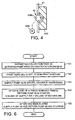
- a filling mode operation of ink-jet printer is described in more detail with reference to FIG 6.
- control unit CNT controls the reciprocating rotation mechanism 46 to insert the ink collection tray 30 between the print head 20U and the rotation drum 10 as in step 101.
- the print head 20U is moved to the non-print position after insertion of the ink collection tray 30 in step 102.
- control unit CNT performs a pump drive process described below.
- the control unit CNT controls the flow of ink from the print head 20U.
- the ink supply pump motor 42M and the ink return pump motor 48M are controlled as described below by the control unit CNT.
- the ink supply pump motor 42M is driven to supply ink from the ink tank TK to the nozzle unit 20 and the heater 51 is energized to heat ink at a most pertinent temperature of each color of inks in step 103. All of the presser chamber 22 is filled with ink from the tank TK by the supply pump 42 and ink reaches each ink-jet nozzles 23. 30 seconds after the ink supply pump motor 42M is driven, as described before. Then, the ink return pump motor 48M is driven. In other words, the ink return pump motor 48M and the ink supply pump motor 42M are not driven, simultaneously.
- the volume of ink supplied by the ink supply pump 42 is greater than that returned by the ink return pump 48 to increase the presser of the ink pressure chamber 22 in step 104.
- ink in the nozzle unit 20 flows out of nozzle unit 20 through the ink-jet nozzles 23 by the difference in the ink volume between ink supply pump 42 and the ink return pump 48. Therefore, a lump of dried ink and gas or air in the ink-jet nozzles 23 are discharged therefrom together with flowing ink and, in addition, gas or air outside the ink-jet nozzles 23 can be prevented from entering into the ink-jet nozzles 23.
- the ink supply pump motor 42M and the ink return pump motor 48M are stopped in step 105. Namely, the ink supply tube 41, the nozzle unit 20 and the ink return tube 47 are filled with ink. Ink flowing out of nozzle unit 20 is collected by the ink collection tray 30, and is drained to the waste ink cassette as a waste ink.
- control unit CNT performs the pump drive process in the filling mode, so that a foreign matter in the ink-jet nozzles 23 of the print head 20U can be discharged by the ink flowing out of the ink-jet nozzles 23. Further the difference in ink flow rate between the ink supply pump 42 and the ink return pump 48 prevent gas or air outside the ink-jet nozzles 23 from entering into the ink-jet nozzles 23 in the pump drive process.
- the ink supply pump motor 42M is driven prior to the operation of ink return pump motor 48M, and the ink return pump motor 48M is driven after ink in the ink-jet nozzles 23 has flowed.
- the ink return pump motor 48M is driven after ink in the ink-jet nozzles 23 has flowed.
- it can prevent a foreign matter which may float around the end surface 24 of the ink-jet nozzles 23 from entering into the ink-jet nozzles 23.
- an ink-jet printer of the present embodiment can print images on a paper sheet with high quality and smoothness.
- the ink-jet printer can fill the ink nozzle unit 20 with ink smoothly by heating ink flowing through the ink supply tube 41.
Applications Claiming Priority (2)
| Application Number | Priority Date | Filing Date | Title |
|---|---|---|---|
| JP10010858A JPH11207993A (ja) | 1998-01-22 | 1998-01-22 | インクジェットプリンタ |
| JP1085898 | 1998-01-22 |
Publications (3)
| Publication Number | Publication Date |
|---|---|
| EP0931662A2 EP0931662A2 (en) | 1999-07-28 |
| EP0931662A3 EP0931662A3 (en) | 1999-12-29 |
| EP0931662B1 true EP0931662B1 (en) | 2006-04-19 |
Family
ID=11762064
Family Applications (1)
| Application Number | Title | Priority Date | Filing Date |
|---|---|---|---|
| EP99300465A Expired - Lifetime EP0931662B1 (en) | 1998-01-22 | 1999-01-22 | Ink-jet printer and method of controlling the same |
Country Status (5)
| Country | Link |
|---|---|
| US (1) | US6213601B1 (ko) |
| EP (1) | EP0931662B1 (ko) |
| JP (1) | JPH11207993A (ko) |
| KR (1) | KR19990067985A (ko) |
| DE (1) | DE69930885T2 (ko) |
Cited By (2)
| Publication number | Priority date | Publication date | Assignee | Title |
|---|---|---|---|---|
| US8282184B2 (en) | 2004-05-27 | 2012-10-09 | Zamtec Limited | Print engine controller employing accumulative correction factor in pagewidth printhead |
| US8308274B2 (en) | 2004-05-27 | 2012-11-13 | Zamtec Limited | Printhead integrated circuit with thermally sensing heater elements |
Families Citing this family (23)
| Publication number | Priority date | Publication date | Assignee | Title |
|---|---|---|---|---|
| JP2002264362A (ja) * | 2001-03-08 | 2002-09-18 | Seiko Instruments Inc | インクジェット式記録装置 |
| JP4887579B2 (ja) * | 2001-07-06 | 2012-02-29 | ブラザー工業株式会社 | 印字装置 |
| JP4337500B2 (ja) * | 2003-10-24 | 2009-09-30 | ソニー株式会社 | 液体吐出装置 |
| US7484831B2 (en) | 2004-05-27 | 2009-02-03 | Silverbrook Research Pty Ltd | Printhead module having horizontally grouped firing order |
| US7328956B2 (en) | 2004-05-27 | 2008-02-12 | Silverbrook Research Pty Ltd | Printer comprising a printhead and at least two printer controllers connected to a common input of the printhead |
| US7735944B2 (en) | 2004-05-27 | 2010-06-15 | Silverbrook Research Pty Ltd | Printer comprising two printhead modules and at least two printer controllers |
| US20070035594A1 (en) * | 2005-08-10 | 2007-02-15 | Brooks Jeffrey B | Ink supply system |
| US7645034B2 (en) | 2006-03-03 | 2010-01-12 | Silverbrook Research Pty Ltd | Pulse damped fluidic architecture |
| US7637602B2 (en) | 2006-03-03 | 2009-12-29 | Silverbrook Research Pty Ltd | Printer with ink flow shutoff valve |
| US7661803B2 (en) | 2006-07-31 | 2010-02-16 | Silverbrook Research Pty Ltd | Inkjet printhead with controlled de-prime |
| JP2008254312A (ja) * | 2007-04-04 | 2008-10-23 | Seiko Epson Corp | 液体吐出装置、液体吐出方法、及び、プログラム |
| JP5211828B2 (ja) * | 2007-06-28 | 2013-06-12 | セイコーエプソン株式会社 | 流体吐出装置、及び、流体吐出装置の制御方法 |
| US20100079559A1 (en) * | 2008-09-29 | 2010-04-01 | Greg Justice | Fluid Circulation System |
| JP5489629B2 (ja) * | 2008-12-05 | 2014-05-14 | キヤノン株式会社 | 記録装置 |
| JP5248421B2 (ja) | 2009-06-22 | 2013-07-31 | ブラザー工業株式会社 | 液体吐出装置 |
| JP2012040712A (ja) * | 2010-08-17 | 2012-03-01 | Seiko Epson Corp | 液体噴射装置 |
| US9751323B2 (en) | 2013-08-27 | 2017-09-05 | Hewlett-Packard Development Company, L.P. | Thermally-induced recirculation of printing fluid |
| JP6322094B2 (ja) * | 2014-09-04 | 2018-05-09 | 理想科学工業株式会社 | インクジェット印刷装置 |
| JP2016168780A (ja) * | 2015-03-13 | 2016-09-23 | 富士フイルム株式会社 | 液体供給装置及び画像形成装置 |
| JP6661576B2 (ja) | 2017-06-28 | 2020-03-11 | キヤノン株式会社 | インクジェット記録装置 |
| US11267254B2 (en) | 2018-09-27 | 2022-03-08 | Hewlett-Packard Development Company, L.P. | Fluid recirculation within printing device reservoir via extraction pump and supply pump |
| JP7166869B2 (ja) | 2018-10-05 | 2022-11-08 | キヤノン株式会社 | 記録装置および記録方法 |
| JP7135017B2 (ja) * | 2020-02-12 | 2022-09-12 | キヤノン株式会社 | インクジェット記録装置 |
Family Cites Families (19)
| Publication number | Priority date | Publication date | Assignee | Title |
|---|---|---|---|---|
| IT1129356B (it) * | 1980-10-31 | 1986-06-04 | Olivetti Ing C Spa | Dispositivo di stampa a getto selettivo di inchiostro |
| GB1562878A (en) * | 1978-05-02 | 1980-03-19 | Itt Creed | Ink-jet printers |
| JPS5869057A (ja) * | 1981-10-20 | 1983-04-25 | Ricoh Co Ltd | インクシエツトプリンタのキヤリツジ装置 |
| GB8328000D0 (en) * | 1983-10-19 | 1983-11-23 | Domino Printing Sciences Ltd | Hydraulic systems |
| JP2728436B2 (ja) * | 1988-06-23 | 1998-03-18 | キヤノン株式会社 | インクジェット記録装置 |
| US4929963A (en) * | 1988-09-02 | 1990-05-29 | Hewlett-Packard Company | Ink delivery system for inkjet printer |
| JP2700341B2 (ja) | 1989-11-29 | 1998-01-21 | キヤノン株式会社 | 液体噴射記録装置 |
| JPH03213350A (ja) * | 1990-01-19 | 1991-09-18 | Canon Inc | インクジェット記録装置 |
| DE69118489T2 (de) * | 1990-11-30 | 1996-08-14 | Canon Kk | Tintenbehälter und Aufzeichnungskopf mit einem solchen Behälter |
| US5485187A (en) * | 1991-10-02 | 1996-01-16 | Canon Kabushiki Kaisha | Ink-jet recording apparatus having improved recovery device |
| JP3114776B2 (ja) * | 1992-06-23 | 2000-12-04 | セイコーエプソン株式会社 | インクジェット式ライン記録ヘッドを用いたプリンタ |
| JP3247558B2 (ja) * | 1994-11-07 | 2002-01-15 | キヤノンアプテックス株式会社 | プリンタ |
| US5956062A (en) * | 1995-01-11 | 1999-09-21 | Canon Kabushiki Kaisha | Liquid jet recording apparatus and recovery method therefor |
| JPH08244250A (ja) * | 1995-01-11 | 1996-09-24 | Canon Inc | 液体吐出記録装置およびその回復方法 |
| JP3684022B2 (ja) * | 1996-04-25 | 2005-08-17 | キヤノン株式会社 | 液体補充方法、液体吐出記録装置および該液体吐出記録装置のメインタンクとして用いられるインクタンク |
| JP3375046B2 (ja) * | 1997-09-19 | 2003-02-10 | 東芝テック株式会社 | インクジェットプリンタ |
| JP3416904B2 (ja) * | 1997-09-19 | 2003-06-16 | 東芝テック株式会社 | インクジェットプリンタ |
| JP2978908B1 (ja) * | 1998-08-19 | 1999-11-15 | 新潟日本電気株式会社 | 静電式インクジェット記録装置におけるインク供給機構 |
| CN101821092B (zh) * | 2007-10-05 | 2014-07-09 | 大日本印刷株式会社 | 带有压纹的脱模纸和其制造方法 |
-
1998
- 1998-01-22 JP JP10010858A patent/JPH11207993A/ja not_active Abandoned
-
1999
- 1999-01-19 KR KR1019990001450A patent/KR19990067985A/ko active IP Right Grant
- 1999-01-22 EP EP99300465A patent/EP0931662B1/en not_active Expired - Lifetime
- 1999-01-22 US US09/235,331 patent/US6213601B1/en not_active Expired - Fee Related
- 1999-01-22 DE DE69930885T patent/DE69930885T2/de not_active Expired - Lifetime
Cited By (2)
| Publication number | Priority date | Publication date | Assignee | Title |
|---|---|---|---|---|
| US8282184B2 (en) | 2004-05-27 | 2012-10-09 | Zamtec Limited | Print engine controller employing accumulative correction factor in pagewidth printhead |
| US8308274B2 (en) | 2004-05-27 | 2012-11-13 | Zamtec Limited | Printhead integrated circuit with thermally sensing heater elements |
Also Published As
| Publication number | Publication date |
|---|---|
| DE69930885T2 (de) | 2006-11-16 |
| DE69930885D1 (de) | 2006-05-24 |
| EP0931662A2 (en) | 1999-07-28 |
| EP0931662A3 (en) | 1999-12-29 |
| KR19990067985A (ko) | 1999-08-25 |
| JPH11207993A (ja) | 1999-08-03 |
| US6213601B1 (en) | 2001-04-10 |
Similar Documents
| Publication | Publication Date | Title |
|---|---|---|
| EP0931662B1 (en) | Ink-jet printer and method of controlling the same | |
| JP3813208B2 (ja) | インクジェット印刷用のマトリクスペン配列 | |
| US7618115B2 (en) | Image forming apparatus | |
| US8113642B2 (en) | Liquid ejection head | |
| US6050671A (en) | Stalagmite dissolving spittoon system for inkjet printheads | |
| US6644778B2 (en) | Stalagmite dissolving spittoon system for inkjet printheads | |
| US5971641A (en) | Carriage driven tray lowering device for an ink jet printer | |
| US6447096B1 (en) | Ink jet recording apparatus and recovery method therefor | |
| EP0903240B1 (en) | Ink-jet printer | |
| US6019460A (en) | Ink jet printer | |
| US8757753B2 (en) | Printing apparatus and printing method | |
| JP2002036603A (ja) | インクジェット記録装置 | |
| US7494200B2 (en) | Recording apparatus and recovery control method | |
| EP0576285A2 (en) | Ink jet recording method and apparatuses | |
| JP3015188B2 (ja) | インクジェット記録装置 | |
| JP3887985B2 (ja) | インクジェットプリンタ | |
| JPH04212864A (ja) | インクジェット記録装置 | |
| JPH08156280A (ja) | インクジェット記録装置および情報処理システム | |
| EP0884185B1 (en) | Image forming method and apparatus therefor | |
| JPH06191060A (ja) | インクジェット記録装置 | |
| JP2004249631A (ja) | インクジェット記録装置 | |
| JP3157931B2 (ja) | インクジェット記録装置 | |
| JP2003182109A (ja) | 液体給排機構および画像形成装置 | |
| JP3162794B2 (ja) | インクジェット記録装置および回復方法 | |
| JP3248544B2 (ja) | インクジェット記録装置 |
Legal Events
| Date | Code | Title | Description |
|---|---|---|---|
| PUAI | Public reference made under article 153(3) epc to a published international application that has entered the european phase |
Free format text: ORIGINAL CODE: 0009012 |
|
| 17P | Request for examination filed |
Effective date: 19990215 |
|
| AK | Designated contracting states |
Kind code of ref document: A2 Designated state(s): DE FR GB |
|
| AX | Request for extension of the european patent |
Free format text: AL;LT;LV;MK;RO;SI |
|
| RAP1 | Party data changed (applicant data changed or rights of an application transferred) |
Owner name: TOSHIBA TEC KABUSHIKI KAISHA |
|
| PUAL | Search report despatched |
Free format text: ORIGINAL CODE: 0009013 |
|
| AK | Designated contracting states |
Kind code of ref document: A3 Designated state(s): AT BE CH CY DE DK ES FI FR GB GR IE IT LI LU MC NL PT SE |
|
| AX | Request for extension of the european patent |
Free format text: AL;LT;LV;MK;RO;SI |
|
| RIC1 | Information provided on ipc code assigned before grant |
Free format text: 6B 41J 2/175 A, 6B 41J 2/17 B |
|
| AKX | Designation fees paid |
Free format text: DE FR GB |
|
| 17Q | First examination report despatched |
Effective date: 20041119 |
|
| GRAP | Despatch of communication of intention to grant a patent |
Free format text: ORIGINAL CODE: EPIDOSNIGR1 |
|
| GRAS | Grant fee paid |
Free format text: ORIGINAL CODE: EPIDOSNIGR3 |
|
| GRAA | (expected) grant |
Free format text: ORIGINAL CODE: 0009210 |
|
| AK | Designated contracting states |
Kind code of ref document: B1 Designated state(s): DE FR GB |
|
| REG | Reference to a national code |
Ref country code: GB Ref legal event code: FG4D |
|
| REF | Corresponds to: |
Ref document number: 69930885 Country of ref document: DE Date of ref document: 20060524 Kind code of ref document: P |
|
| ET | Fr: translation filed | ||
| PLBE | No opposition filed within time limit |
Free format text: ORIGINAL CODE: 0009261 |
|
| STAA | Information on the status of an ep patent application or granted ep patent |
Free format text: STATUS: NO OPPOSITION FILED WITHIN TIME LIMIT |
|
| 26N | No opposition filed |
Effective date: 20070122 |
|
| PGFP | Annual fee paid to national office [announced via postgrant information from national office to epo] |
Ref country code: FR Payment date: 20080108 Year of fee payment: 10 |
|
| REG | Reference to a national code |
Ref country code: FR Ref legal event code: ST Effective date: 20091030 |
|
| PG25 | Lapsed in a contracting state [announced via postgrant information from national office to epo] |
Ref country code: FR Free format text: LAPSE BECAUSE OF NON-PAYMENT OF DUE FEES Effective date: 20090202 |
|
| PGFP | Annual fee paid to national office [announced via postgrant information from national office to epo] |
Ref country code: DE Payment date: 20120118 Year of fee payment: 14 |
|
| PG25 | Lapsed in a contracting state [announced via postgrant information from national office to epo] |
Ref country code: DE Free format text: LAPSE BECAUSE OF NON-PAYMENT OF DUE FEES Effective date: 20130801 |
|
| REG | Reference to a national code |
Ref country code: DE Ref legal event code: R119 Ref document number: 69930885 Country of ref document: DE Effective date: 20130801 |
|
| PGFP | Annual fee paid to national office [announced via postgrant information from national office to epo] |
Ref country code: GB Payment date: 20180117 Year of fee payment: 20 |
|
| REG | Reference to a national code |
Ref country code: GB Ref legal event code: PE20 Expiry date: 20190121 |
|
| PG25 | Lapsed in a contracting state [announced via postgrant information from national office to epo] |
Ref country code: GB Free format text: LAPSE BECAUSE OF EXPIRATION OF PROTECTION Effective date: 20190121 |