EP0930657A1 - Zweidimensionaler Bilddetektor und Verfahren zu dessen Herstellung - Google Patents
Zweidimensionaler Bilddetektor und Verfahren zu dessen Herstellung Download PDFInfo
- Publication number
- EP0930657A1 EP0930657A1 EP99100884A EP99100884A EP0930657A1 EP 0930657 A1 EP0930657 A1 EP 0930657A1 EP 99100884 A EP99100884 A EP 99100884A EP 99100884 A EP99100884 A EP 99100884A EP 0930657 A1 EP0930657 A1 EP 0930657A1
- Authority
- EP
- European Patent Office
- Prior art keywords
- dimensional image
- image detector
- set forth
- active matrix
- adhesive agent
- Prior art date
- Legal status (The legal status is an assumption and is not a legal conclusion. Google has not performed a legal analysis and makes no representation as to the accuracy of the status listed.)
- Granted
Links
- 238000000034 method Methods 0.000 title claims description 54
- 230000008569 process Effects 0.000 title claims description 27
- 238000004519 manufacturing process Methods 0.000 title claims description 19
- 239000000758 substrate Substances 0.000 claims abstract description 383
- 239000011159 matrix material Substances 0.000 claims abstract description 143
- 239000004065 semiconductor Substances 0.000 claims abstract description 129
- 239000000853 adhesive Substances 0.000 claims abstract description 128
- 239000003990 capacitor Substances 0.000 claims abstract description 38
- 238000003860 storage Methods 0.000 claims abstract description 38
- 229910004613 CdTe Inorganic materials 0.000 claims abstract description 24
- 239000000463 material Substances 0.000 claims abstract description 24
- 229910004611 CdZnTe Inorganic materials 0.000 claims abstract description 21
- 239000002245 particle Substances 0.000 claims description 29
- 230000005855 radiation Effects 0.000 claims description 28
- 230000000903 blocking effect Effects 0.000 claims description 19
- 230000001681 protective effect Effects 0.000 claims description 16
- 230000035945 sensitivity Effects 0.000 claims description 16
- 150000001875 compounds Chemical class 0.000 claims description 6
- 230000035699 permeability Effects 0.000 claims description 5
- 239000011248 coating agent Substances 0.000 claims description 3
- 238000000576 coating method Methods 0.000 claims description 3
- 238000000016 photochemical curing Methods 0.000 claims description 2
- 229920001187 thermosetting polymer Polymers 0.000 claims description 2
- 230000004044 response Effects 0.000 abstract description 5
- 239000010408 film Substances 0.000 description 87
- 238000000151 deposition Methods 0.000 description 22
- 238000010438 heat treatment Methods 0.000 description 21
- 229910052751 metal Inorganic materials 0.000 description 16
- 239000002184 metal Substances 0.000 description 16
- 239000004020 conductor Substances 0.000 description 15
- 239000011669 selenium Substances 0.000 description 14
- 229910021417 amorphous silicon Inorganic materials 0.000 description 11
- 230000008021 deposition Effects 0.000 description 11
- 239000011521 glass Substances 0.000 description 11
- 238000000059 patterning Methods 0.000 description 7
- 238000003825 pressing Methods 0.000 description 7
- 238000001704 evaporation Methods 0.000 description 6
- 230000008020 evaporation Effects 0.000 description 6
- 238000002488 metal-organic chemical vapour deposition Methods 0.000 description 6
- 229910004205 SiNX Inorganic materials 0.000 description 5
- VYPSYNLAJGMNEJ-UHFFFAOYSA-N Silicium dioxide Chemical compound O=[Si]=O VYPSYNLAJGMNEJ-UHFFFAOYSA-N 0.000 description 5
- 230000001070 adhesive effect Effects 0.000 description 5
- 229910052782 aluminium Inorganic materials 0.000 description 5
- 239000003795 chemical substances by application Substances 0.000 description 5
- 238000005229 chemical vapour deposition Methods 0.000 description 5
- 230000000694 effects Effects 0.000 description 5
- 238000007650 screen-printing Methods 0.000 description 5
- 229910052814 silicon oxide Inorganic materials 0.000 description 5
- 230000007812 deficiency Effects 0.000 description 4
- 229910052737 gold Inorganic materials 0.000 description 4
- 239000004973 liquid crystal related substance Substances 0.000 description 4
- 150000002739 metals Chemical class 0.000 description 4
- 230000003647 oxidation Effects 0.000 description 4
- 238000007254 oxidation reaction Methods 0.000 description 4
- 239000012466 permeate Substances 0.000 description 4
- 239000004033 plastic Substances 0.000 description 4
- 229920003023 plastic Polymers 0.000 description 4
- 229910052715 tantalum Inorganic materials 0.000 description 4
- 239000004925 Acrylic resin Substances 0.000 description 3
- 229920000178 Acrylic resin Polymers 0.000 description 3
- 238000002347 injection Methods 0.000 description 3
- 239000007924 injection Substances 0.000 description 3
- 239000002923 metal particle Substances 0.000 description 3
- 239000002994 raw material Substances 0.000 description 3
- 238000000926 separation method Methods 0.000 description 3
- 229910017107 AlOx Inorganic materials 0.000 description 2
- 238000010521 absorption reaction Methods 0.000 description 2
- 239000003513 alkali Substances 0.000 description 2
- 239000002585 base Substances 0.000 description 2
- 230000008901 benefit Effects 0.000 description 2
- 229910052802 copper Inorganic materials 0.000 description 2
- 238000010586 diagram Methods 0.000 description 2
- FRLYMSHUDNORBC-UHFFFAOYSA-N diisopropylzinc Chemical compound [Zn+2].C[CH-]C.C[CH-]C FRLYMSHUDNORBC-UHFFFAOYSA-N 0.000 description 2
- AXAZMDOAUQTMOW-UHFFFAOYSA-N dimethylzinc Chemical compound C[Zn]C AXAZMDOAUQTMOW-UHFFFAOYSA-N 0.000 description 2
- 239000003822 epoxy resin Substances 0.000 description 2
- 238000011049 filling Methods 0.000 description 2
- 230000008014 freezing Effects 0.000 description 2
- 238000007710 freezing Methods 0.000 description 2
- LNEPOXFFQSENCJ-UHFFFAOYSA-N haloperidol Chemical compound C1CC(O)(C=2C=CC(Cl)=CC=2)CCN1CCCC(=O)C1=CC=C(F)C=C1 LNEPOXFFQSENCJ-UHFFFAOYSA-N 0.000 description 2
- 229910052739 hydrogen Inorganic materials 0.000 description 2
- 239000001257 hydrogen Substances 0.000 description 2
- 229910052738 indium Inorganic materials 0.000 description 2
- 238000010030 laminating Methods 0.000 description 2
- 238000002156 mixing Methods 0.000 description 2
- 238000000206 photolithography Methods 0.000 description 2
- 229920002037 poly(vinyl butyral) polymer Polymers 0.000 description 2
- 229920000647 polyepoxide Polymers 0.000 description 2
- 239000004814 polyurethane Substances 0.000 description 2
- 229920002635 polyurethane Polymers 0.000 description 2
- 238000007639 printing Methods 0.000 description 2
- 230000009467 reduction Effects 0.000 description 2
- 229910052709 silver Inorganic materials 0.000 description 2
- 229910000679 solder Inorganic materials 0.000 description 2
- 230000003068 static effect Effects 0.000 description 2
- 229920000468 styrene butadiene styrene block copolymer Polymers 0.000 description 2
- -1 styrene-ethylenebutylene-styrene Chemical class 0.000 description 2
- 238000005979 thermal decomposition reaction Methods 0.000 description 2
- 239000010409 thin film Substances 0.000 description 2
- 238000011282 treatment Methods 0.000 description 2
- 238000001771 vacuum deposition Methods 0.000 description 2
- OKTJSMMVPCPJKN-UHFFFAOYSA-N Carbon Chemical compound [C] OKTJSMMVPCPJKN-UHFFFAOYSA-N 0.000 description 1
- 239000004593 Epoxy Substances 0.000 description 1
- 206010073306 Exposure to radiation Diseases 0.000 description 1
- UFHFLCQGNIYNRP-UHFFFAOYSA-N Hydrogen Chemical compound [H][H] UFHFLCQGNIYNRP-UHFFFAOYSA-N 0.000 description 1
- 206010034972 Photosensitivity reaction Diseases 0.000 description 1
- 239000004642 Polyimide Substances 0.000 description 1
- BUGBHKTXTAQXES-UHFFFAOYSA-N Selenium Chemical compound [Se] BUGBHKTXTAQXES-UHFFFAOYSA-N 0.000 description 1
- XUIMIQQOPSSXEZ-UHFFFAOYSA-N Silicon Chemical compound [Si] XUIMIQQOPSSXEZ-UHFFFAOYSA-N 0.000 description 1
- 239000011358 absorbing material Substances 0.000 description 1
- NIXOWILDQLNWCW-UHFFFAOYSA-N acrylic acid group Chemical group C(C=C)(=O)O NIXOWILDQLNWCW-UHFFFAOYSA-N 0.000 description 1
- 229910052793 cadmium Inorganic materials 0.000 description 1
- BDOSMKKIYDKNTQ-UHFFFAOYSA-N cadmium atom Chemical compound [Cd] BDOSMKKIYDKNTQ-UHFFFAOYSA-N 0.000 description 1
- VQNPSCRXHSIJTH-UHFFFAOYSA-N cadmium(2+);carbanide Chemical compound [CH3-].[CH3-].[Cd+2] VQNPSCRXHSIJTH-UHFFFAOYSA-N 0.000 description 1
- 229910052799 carbon Inorganic materials 0.000 description 1
- 239000000919 ceramic Substances 0.000 description 1
- 238000006243 chemical reaction Methods 0.000 description 1
- 239000002131 composite material Substances 0.000 description 1
- 239000013078 crystal Substances 0.000 description 1
- 230000002542 deteriorative effect Effects 0.000 description 1
- HQWPLXHWEZZGKY-UHFFFAOYSA-N diethylzinc Chemical compound CC[Zn]CC HQWPLXHWEZZGKY-UHFFFAOYSA-N 0.000 description 1
- 229920001971 elastomer Polymers 0.000 description 1
- 238000005516 engineering process Methods 0.000 description 1
- 238000005530 etching Methods 0.000 description 1
- ILXWFJOFKUNZJA-UHFFFAOYSA-N ethyltellanylethane Chemical compound CC[Te]CC ILXWFJOFKUNZJA-UHFFFAOYSA-N 0.000 description 1
- 239000012530 fluid Substances 0.000 description 1
- 239000007789 gas Substances 0.000 description 1
- 150000002431 hydrogen Chemical class 0.000 description 1
- 230000006872 improvement Effects 0.000 description 1
- 229910010272 inorganic material Inorganic materials 0.000 description 1
- 239000011147 inorganic material Substances 0.000 description 1
- 230000001678 irradiating effect Effects 0.000 description 1
- 238000003475 lamination Methods 0.000 description 1
- 230000004048 modification Effects 0.000 description 1
- 238000012986 modification Methods 0.000 description 1
- 229910052759 nickel Inorganic materials 0.000 description 1
- 238000007645 offset printing Methods 0.000 description 1
- 230000036211 photosensitivity Effects 0.000 description 1
- 238000007747 plating Methods 0.000 description 1
- 229910021420 polycrystalline silicon Inorganic materials 0.000 description 1
- 229920001721 polyimide Polymers 0.000 description 1
- 238000002601 radiography Methods 0.000 description 1
- 229910052711 selenium Inorganic materials 0.000 description 1
- 229910052710 silicon Inorganic materials 0.000 description 1
- 239000010703 silicon Substances 0.000 description 1
- 229920006132 styrene block copolymer Polymers 0.000 description 1
- 229910052714 tellurium Inorganic materials 0.000 description 1
- 238000004227 thermal cracking Methods 0.000 description 1
- 229920001169 thermoplastic Polymers 0.000 description 1
- 239000004416 thermosoftening plastic Substances 0.000 description 1
- 235000016804 zinc Nutrition 0.000 description 1
Images


Classifications
-
- H—ELECTRICITY
- H01—ELECTRIC ELEMENTS
- H01L—SEMICONDUCTOR DEVICES NOT COVERED BY CLASS H10
- H01L27/00—Devices consisting of a plurality of semiconductor or other solid-state components formed in or on a common substrate
- H01L27/14—Devices consisting of a plurality of semiconductor or other solid-state components formed in or on a common substrate including semiconductor components sensitive to infrared radiation, light, electromagnetic radiation of shorter wavelength or corpuscular radiation and specially adapted either for the conversion of the energy of such radiation into electrical energy or for the control of electrical energy by such radiation
- H01L27/144—Devices controlled by radiation
- H01L27/146—Imager structures
- H01L27/14665—Imagers using a photoconductor layer
- H01L27/14676—X-ray, gamma-ray or corpuscular radiation imagers
-
- H—ELECTRICITY
- H01—ELECTRIC ELEMENTS
- H01L—SEMICONDUCTOR DEVICES NOT COVERED BY CLASS H10
- H01L2924/00—Indexing scheme for arrangements or methods for connecting or disconnecting semiconductor or solid-state bodies as covered by H01L24/00
- H01L2924/30—Technical effects
- H01L2924/35—Mechanical effects
- H01L2924/351—Thermal stress
Definitions
- the present invention relates to a two-dimensional image detector for detecting an image by radiation such as X-rays, visible light, infrared light, etc., and a process for manufacturing such a two-dimensional image detector.
- a device conventionally known as a two-dimensional image detector for detecting an image by radiation has such a structure that semiconductor sensors for sensing X-rays to generate charges (electrons-holes) are two-dimensionally disposed, and electric switches are provided for the respective sensors so as to read out the charges of the sensors column by column by sequentially turning on the electric switches row by row.
- the specific structure and the principle of the two-dimensional image detector are described in, for example, references: D. L. Lee, et al., "A New Digital Detector for Projection Radiography", SPIE, 2432, pp. 237-249, 1995; and L. S.
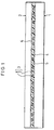
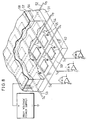
- Fig. 8 is a depiction of the structure of the two-dimensional radiation image detector.
- Fig. 9 is a depiction of the cross section showing the structure of each pixel of the two-dimensional radiation image detector.
- the two-dimensional radiation image detector includes an active matrix substrate having a glass substrate 51 on which XY matrix-form electrode wiring (gate electrodes 52 and source electrodes 53), TFTs (thin film transistors) 54, and charge storage capacitors (Cs) 55, etc. are formed.
- XY matrix-form electrode wiring gate electrodes 52 and source electrodes 53
- TFTs thin film transistors
- Cs charge storage capacitors
- the charge storage capacitor 55 includes a Cs electrode 59 and a pixel electrode 60 connected to a drain electrode of the TFT 54, arranged so that the Cs electrode 59 faces the pixel electrode 60 through an insulating film 61.
- the photoconductive film 56 is formed by a semiconductor material for generating charges on exposure to radiation such as X-rays. According to the above references, amorphous selenium (a-Se) having a high dark resistance and showing satisfactory photoconduction characteristics on exposure to X-ray irradiation is used.
- the photoconductive film 56 is formed by a vacuum evaporation method to have a thickness ranging from 300 to 600 ⁇ m.
- an active matrix substrate formed in the process of manufacturing a liquid crystal display device can be utilized.
- an active matrix substrate used for an active-matrix type liquid crystal display device includes TFTs formed by amorphous silicon (a-Si) or poly-silicon (p-Si), XY matrix electrodes, and charge storage capacitors. Therefore, by only slightly changing the design, the active matrix substrate formed in the process of manufacturing the liquid crystal display device can be easily utilized as the active matrix substrate for use in the two-dimensional radiation image detector.
- a charge blocking layer 62 as a thin insulating layer is formed between the photoconductive film 56 and the charge storage capacitor 55, and functions as a blocking-type photodiode for blocking the flow of the charges from one side.
- the charges accumulated in the charge storage capacitors 55 can be taken out via source electrodes S1, S2, S3, ..., Sn by setting the TFTs 54 to the open state in accordance with input signals of gate electrodes G1, G2, G3, ..., Gn. Since the gate electrodes 52, the source electrodes 53, the TFTs 54, the charge storage capacitors 55, etc. are all provided in the XY-matrix form, X-ray image information can be obtained two-dimensionally by sequentially scanning the signals inputted to the gate electrodes G1, G2, G3, ..., Gn line by line.
- the two-dimensional image detector also functions as a two-dimensional image detector for detecting an image by visible light and infrared light.
- a-Se is used as the photoconductive film 56.
- the response of a-Se is not good because the photocurrent produced by a-Se has distributed conduction characteristics typical of amorphous materials. Further, since the sensitivity (S/N ratio) of a-Se to X-rays is not sufficient, information cannot be read out until the charge storage capacitors 55 are fully charged by long-time irradiation with X-rays.
- the dielectric layer 57 is provided between the photoconductive film 56 and the top electrode 58 for reduction of the leakage current (dark current) and protection from the high voltage. Since the charges remain in the dielectric layer 57, a sequence for removing the remaining charges every frame must be added, thereby causing such a problem that the two-dimensional image detector can be utilized for only shooting static images.
- the photoconductive film 56 made of a crystalline (or polycrystalline) photoconductive material having excellent sensitivity (S/N ratio) to X-rays in place of a-Se.
- S/N ratio sensitivity to X-rays
- the charge storage capacitors 55 can be sufficiently charged even by short-time irradiation with X-rays, and the application of a high voltage to the photoconductive film 56 becomes unnecessary, thereby eliminating the need for providing the dielectric layer 57.
- adding the sequence for removing the remaining charges every frame is not required, thereby making it possible to shoot dynamic images.
- Photoconductive materials known to have excellent sensitivity to X-rays are CdTe, CdZnTe, etc.
- X-ray photoelectric absorption of a material is proportional to the fifth power of the effective atomic number of the absorbing material.
- the atomic number of Se is 34 and the effective atomic number of CdTe is 50, about 6.9-times improvement in sensitivity can be expected.
- CdTe or CdZnTe as the photoconductive film 56 of the two-dimensional radiation image detector instead of a-Se, the following problem arises.
- the vacuum evaporation method can be employed as the method for depositing the film, and the film can be deposited at room temperatures.
- the film deposition on the active matrix substrate was easy.
- the MBE method and the MOCVD method are known as methods for depositing the film, and particularly, the MOCVD method is suitable, considering deposition of the film over the large-area substrate.
- CdTe or CdZnTe by the MOCVD method requires a high temperature of about 400°C, because thermal decomposition of organic cadmium (DMCd) as a raw material occurs at about 300°C, and thermal decomposition of organic telluriums (DETe and DiPTe) as raw materials occurs at about 400°C and 350°C, respectively.
- DMCd organic cadmium
- DETe and DiPTe organic telluriums
- the above-mentioned TFT 54 formed on the active matrix substrate includes an a-Si film or a p-Si film as a semiconductor layer. These films are deposited at temperatures ranging from about 300 to 350°C while adding hydrogen (H 2 ), so as to improve their semiconductor characteristics.
- the TFT 54 formed in this way has a heat resistance up to about 300°C. Accordingly, treating the TFT 54 at temperatures higher than 300°C causes hydrogen to come out of the a-Si film or the p-Si film, thereby deteriorating the semiconductor characteristics.
- An object of the present invention is to provide a two-dimensional image detector which has an improved response and is capable of dealing with the dynamic images by using CdTe, CdZnTe, etc. as a material of a semiconductor layer having photoconductivity, and a process for manufacturing such a two-dimensional image detector.
- a two-dimensional image detector in accordance with the present invention is characterized in including:
- the active matrix substrate including the switching elements and the charge storage capacitors and the opposing substrate including the electrode layer and the semiconductor layer are disposed so as to face each other, and connected to each other by the connection layer.
- the semiconductor layer is electrically and physically connected to the charge storage capacitors through the connection layer, it is not required to be disposed directly on the active matrix substrate. Therefore, even a semiconductor material that requires the heat treatment at a temperature higher than the heat resistance temperature of the switching element (temperature the switching element can resist) in the film deposition step can be used for the semiconductor layer.
- the semiconductor material having excellent sensitivity to radiation such as X-rays, visible light, and infrared light can be freely chosen and used for the semiconductor layer.
- the semiconductor material with excellent sensitivity for the semiconductor layer the time required for storing necessary charges is shortened. Therefore, the voltage applied to the electrode section can be set lower than the conventional value. It is thus possible to omit the dielectric layer which were conventionally provided between the semiconductor layer and the electrode section for protection from the high voltage.
- a process for manufacturing a two-dimensional image detector is characterized in including the steps of:
- the active matrix substrate including the switching elements and the charge storage capacitors having the pixel electrodes is prepared first in the step (a), and the opposing substrate including the electrode layer and the semiconductor layer showing photoconductivity is prepared in the step (b). Then, in the step (c), the active matrix substrate is connected to the opposing substrate with the connection layer having anisotropic conductivity.
- the semiconductor layer is formed not on the active matrix substrate but on the opposing substrate, and then electrically and physically connected to the active matrix substrate through the connection layer having anisotropic conductivity. Therefore, the semiconductor layer can be formed by using the material which could not be conventionally used from the viewpoint of the heat resistance temperature of the switching element, i.e., the semiconductor material which requires the heat treatment at a high temperature in the film deposition step.
- the semiconductor material having excellent sensitivity to radiation such as X-rays and light such as visible light and infrared light can be freely chosen and used for the semiconductor layer.
- the semiconductor material with excellent sensitivity for the semiconductor layer the time required for storing necessary charges is shortened. Therefore, the voltage applied to the electrode section can be set lower than the conventional value. It is thus possible to omit the dielectric layer which were conventionally provided between the semiconductor layer and the electrode section for protection from the high voltage.
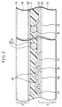
- a two-dimensional image detector in accordance with the present embodiment includes an active matrix substrate 1 on which charge storage capacitors (Cs) 4 and TFTs (thin film transistors) 5 as switching elements are formed, and an opposing substrate 2 on which connection electrodes 6 are formed.
- the active matrix substrate 1 and the opposing substrate 2 are adhered to each other by an anisotropic conductive adhesive agent 3 as an anisotropic conductive material.
- anisotropic conductive material is a generic name of materials whose conduction characteristics have anisotropy.
- the anisotropic conductive adhesive agent 3 according to this embodiment is produced by mixing conductive particles 8 with an insulating adhesive agent 7.
- the active matrix substrate 1 includes a glass substrate 9 on which XY matrix-form electrode wiring formed by gate electrodes 10 and source electrodes 11, the charge storage capacitors 4, the TFTs 5, etc. are formed. Namely, the electrode wiring, the charge storage capacitors 4, and the TFTs 5 constitute a pixel array layer.
- the glass substrate 9 is a no-alkali glass substrate (for example, #7059 or #1737 manufactured by Corning Inc.) on which the gate electrode 10 made of a film of metals such as Ta is formed.
- the gate electrode 10 is obtained by depositing a film of Ta, etc. to have a thickness of about 3000 ⁇ by sputter evaporation, and then patterning the film to have a desired pattern.
- a Cs electrode 12 of the charge storage capacitor 4 is formed.
- an insulating film 13 made of SiN x or SiO x is deposited to have a thickness of about 3500 ⁇ by the CVD method.
- the insulating film 13 functions as a gate insulating film of the TFT 5 and as a dielectric layer between the electrodes of the charge storage capacitor 4.
- an anodic oxidation coating produced by anodic oxidation of the gate electrode 10 and the Cs electrode 12 may be used in combination with SiN x or SiO x .
- an a-Si film (i layer) 14 as a channel section of the TFT 5 and an a-Si film (n + layer) 15 for bringing source and drain electrodes into contact with each other are deposited by the CVD method to have thicknesses of about 1000 ⁇ and 400 ⁇ , respectively, and the films are patterned to have desired patterns.
- the source electrode 11 and the drain electrode also functioning as a pixel electrode 16
- the source electrode 11 and the pixel electrode 16 are obtained by depositing the metal films to have a thickness of about 3000 ⁇ by sputter evaporation, and patterning them to have desired patterns.
- an insulating protective film 17 is formed so as to insulate and protect the area except for the opening section of the pixel electrode 16.
- the insulating protective film 17 is obtained by depositing an insulating film made of SiN x or SiO x by the CVD method to have a thickness of about 3000 ⁇ , and patterning it to have a desired pattern.
- organic films made of acrylic, polyimide, etc. can be used in place of the insulating films made of inorganic materials. In this manner, the active matrix substrate 1 is formed.
- the TFT 5 having an anti-staggered structure including a-Si is used as the TFT element of the active matrix substrate 1, but the TFT element is not limited to this structure. Namely, p-Si or a staggered structure is also acceptable.
- the active matrix substrate 1 can be formed by the same process as that of the active matrix substrate formed in the process of manufacturing the liquid crystal display device.
- the opposing substrate 2 includes as a support substrate a semiconductor substrate (semiconductor layer) 18 having photoconductivity with respect to radiation such as X-rays.
- a semiconductor substrate semiconductor layer
- a compound semiconductor such as CdTe or CdZnTe is used in the semiconductor substrate 18.
- the thickness of the semiconductor substrate 18 is about 0.5 mm.
- the semiconductor substrate 18 is a substrate made of a crystal, and easily formed by the Bridgeman method, the gradient freezing method, the travel heating method, etc.
- a top electrode (electrode section) 19 is formed by an X-ray permeable metal such as Al.
- connection electrode 6 On the other surface of the semiconductor substrate 18, a charge blocking layer 20 is formed on the almost entire surface, and then the connection electrode 6 is formed.
- the charge blocking layer 20 is an insulating layer made of AlO x , and has a thickness of about 300 ⁇ .
- the connection electrode 6 is formed by depositing a metal film such as Ta and Al by sputter evaporation to have a thickness of about 2000 ⁇ , and patterning it to have a desired pattern.
- the connection electrode 6 is formed at the position corresponding to the pixel electrode 16 formed on the active matrix substrate 1.
- the two-dimensional image detector according to the present embodiment is formed by disposing the active matrix substrate 1 and the opposing substrate 2 obtained by the above process so that each of the pixel electrodes 16 faces the connection electrode 6, filling the space therebetween with the anisotropic conductive material, and adhering the two substrates by pressure.
- the anisotropic conductive adhesive agent 3 is used as the anisotropic conductive material, which is produced by dispersing the conductive particles 8 made of metal particles, etc. into the insulating adhesive agent 7 such as an epoxy thermosetting-type adhesive agent in the form of paste, etc.
- the anisotropic conductive adhesive agent 3 the agent whose setting is facilitated by a heat treatment at about 160°C is used.
- FIG. 3 An equivalent circuit diagram of each pixel of the two-dimensional image detector is shown in Fig. 3. With reference to Figs. 2 and 3, the operational principle of the two-dimensional image detector will be explained below.
- the semiconductor substrate 18 made of CdTe or CdZnTe is exposed to X-rays, charges (electrons-holes) are generated in the semiconductor substrate 18 by the effect of photoconductivity.
- the charge storage capacitor 4 and the semiconductor substrate 18 are connected in series via the pixel electrode 16, the anisotropic conductive adhesive agent 3, and the connection electrode 6. Therefore, when a voltage is applied across the top electrode 19 and the Cs electrode 12, the negative and positive charges generated in the semiconductor substrate 18 move toward the anode side and the cathode side, respectively. As a result, the charges are accumulated in the charge storage capacitor 4.
- the charge blocking layer 20 as a thin insulating layer is formed between the semiconductor substrate 18 and the connection electrode 6, and functions as a blocking-type photodiode having a MIS (Metal-Insulator-Semiconductor) structure for blocking the injection of charges from one side.
- This function contributes to the reduction of the dark current generated when no X-rays come into the semiconductor substrate 18. Namely, when a positive voltage is applied to the top electrode 19, the charge blocking layer 20 blocks the injection of electrons from the connection electrode 6 to the semiconductor substrate 18.
- a charge blocking layer is also provided between the semiconductor substrate 18 and the top electrode 19 so as to block the injection of holes from the top electrode 19 to the semiconductor substrate 18, thereby further reducing the dark current.
- a heterojunction structure using a lamination film of CdTe/CdS, etc., a PIN junction structure, and a Schottky junction structure are also acceptable as the structure of the blocking-type photodiode, i.e., the structure of the charge blocking layer 20.
- the charges accumulated in the charge storage capacitor 4 can be taken out of the source electrode 11 by setting the TFT 5 to be in the open state by the input signal of the gate electrode 10.
- the electrode wiring (the gate electrodes 10 and the source electrodes 11), the TFTs 5, the charge storage capacitors 4, and other members are all arranged in the XY-matrix form like the conventional example shown in Fig. 8. Therefore, X-ray image information can be two-dimensionally obtained by sequentially scanning the signals input to the gate electrodes G1, G2, G3, ..., Gn line by line.
- the basic operational principle of the two-dimensional image detector of the present embodiment is the same as that of the image detector shown as the conventional example.
- the active matrix substrate 1 and the opposing substrate 2 are electrically and physically adhered to each other by the anisotropic conductive adhesive agent 3 produced by dispersing the conductive particles 8 into the adhesive agent 7.
- the active matrix substrate 1 is equipped with the lattice-form electrode wiring, and a plurality of TFTs 5 and pixel electrodes 16, provided at the respective lattice points.
- the opposing substrate 2 is equipped with the semiconductor substrate 18 having photoconductivity, formed on the almost entire surface of the opposing substrate 2.
- the restriction on the film deposition temperature of the photoconductor due to the heat resistance of the active matrix substrate becomes less severe, which has been a problem in the case of directly depositing the photoconductive semiconductor on the active matrix substrate as in the conventional two-dimensional image detector.
- the semiconductor materials for example, CdTe and CdZnTe
- the temperature required for causing the thermosetting-type anisotropic conductive adhesive agent to set is restricted.
- the active matrix substrate usually has a heat resistance up to about 250°C, an adhesive agent whose setting proceeds under such a temperature can be easily chosen, thereby causing no trouble in using CdTe or CdZnTe as the semiconductor material.
- CdTe or CdZnTe can be used as the semiconductor substrate 18 for the above-described reasons, sensitivity to X-rays is improved compared with the conventional two-dimensional image detector using a-Se, and the dielectric layer is not required to be provided between the semiconductor substrate 18 and the top electrode 19. It is thus possible to obtain image data corresponding to dynamic images, i.e., to obtain image data at a rate of 33 msec/frame.
- connection electrodes 6 are formed on the side of the semiconductor substrate 18, which side faces the active matrix substrate 1, so that the connection electrodes 6 are separately provided for the respective pixels in correspondence with a plurality of pixel electrodes 16 formed on the active matrix substrate 1. Therefore, the pixels on the semiconductor substrate 18 of the opposing substrate 2 are electrically separated from each other. As a result, the charges generated in the semiconductor substrate 18 by incidence of radiation or a light beam are collected on only the connection electrode 6 corresponding to the incidence location, thereby limiting the electric crosstalk caused by the charges moving to the surrounding pixels.
- connection electrode 6 having a maximum size within each pixel is formed on the semiconductor substrate 18, and the area of the pixel electrode 16 is set to be less than that of the connection electrode 6 in each pixel.
- This arrangement enables efficient collection of the charges generated in the semiconductor by incidence of X-rays and light beams, and limits the electric crosstalk between the adjacent pixels even when the active matrix substrate 1 and the opposing substrate 2 are not accurately placed in the correct positions in adhering the two substrates.
- the pixel electrode 16 was arranged to have a substantially square shape whose side length was about 80 ⁇ m, and the connection electrode 6 was arranged to have a substantially square shape whose side length is about 120 ⁇ m. With this arrangement, a margin of ⁇ 20 ⁇ m was secured in adhering the active matrix substrate 1 and the opposing substrate 2.
- the conductive particle 8 available here includes metal particles such as Ni and Ag or these metal particles plated with Au, a carbon particle, a metal-film coated plastic particle, i.e., a plastic particle plated with Au or Au/Ni, a transparent conductive particle such as ITO, and a conductive particle composite plastic which is produced by mixing Ni particles with polyurethane.
- the metal-film coated plastic particle having excellent elasticity was used so as to accommodate variations in thickness of the upper and lower substrates (the active matrix substrate 1 and the opposing substrate 2).
- the adhesive agent 7 available here includes adhesive agents of thermosetting type, thermoplastic type, and photo-curing type.
- the adhesive agent of each type has the following characteristics.
- thermosetting-type adhesive agent is the agent whose setting is facilitated by only applying a heat treatment, and has various kinds such as epoxy resins, acrylic resins, and polyurethane.
- epoxy resins having excellent reliability in their heat resistance and adhesive property can realize a highly-reliable two-dimensional image detector.
- the thermoplastic-type adhesive agent has reversibility in setting and softening, and includes various kinds such as SBS (styrene-butadiene-styrene block copolymer), SEBS (styrene-ethylenebutylene-styrene block copolymer), and PVB (polyvinyl butyral).
- SBS styrene-butadiene-styrene block copolymer
- SEBS styrene-ethylenebutylene-styrene block copolymer
- PVB polyvinyl butyral
- the adhesive agent of this type is the agent whose setting is facilitated by irradiation of light such as ultraviolet rays, and requires no heat treatment. Therefore, when adhering the active matrix substrate 1 and the opposing substrate 2, even if their thermal expansion coefficients are different, warpage of the substrates and separation of adhered surfaces are not caused by the difference in the thermal expansion coefficients. It is thus possible to adhere the substrates having relatively large areas.
- the glass substrate #1737 manufactured by Corning Inc. used in the active matrix substrate 1 has the thermal expansion coefficient of 37.8 ⁇ 10 -7 (/°C), while CdTe has the thermal expansion coefficient of 47 ⁇ 10 -7 (/°C) which is different from the above value. Therefore, in adhering the two members using the photo-curing-type adhesive agent requiring no heat treatment is preferable, if possible.
- the Cs electrode 12 and the pixel electrode 16 are preferably formed by transparent electrodes such as ITO. This is because the anisotropic conductive adhesive agent 3 located in the gap between the active matrix substrate 1 and the opposing substrate 2 must be irradiated with light, when the two substrates are kept adhered to each other. By irradiation with light incident from the active matrix substrate 1 through the transparent Cs electrode 12 and pixel electrode 16, setting of the anisotropic conductive adhesive agent 3 can be facilitated.
- the adhesive agent 7 of the above types to be used for the anisotropic conductive adhesive agent 3 can be selected depending on the uses. In the present embodiment, taking the adhesion strength seriously, the thermosetting-type adhesive agent is used.
- the paste-type adhesive agent can be easily applied to a large-area substrate by, for example, the screen printing method.
- the film-type adhesive agent has excellent uniformity in its thickness, thereby easily achieving a uniform thickness of the adhesive agent even when adhering the large-area substrates.
- the paste-type adhesive agent was adopted.
- Figs. 4(a) to 4(d) show the process of adhering the two substrates to each other.
- the anisotropic conductive adhesive agent 3 is applied by the screen printing method to the almost entire surface of one of the active matrix substrate 1 and the opposing substrate 2 to have a thickness of about 10 ⁇ m, to which surface the other of the two substrates is to be adhered. If the flatness of the adhesive agent 7 after applied is not sufficient, it may be improved by a heat treatment at low temperatures ranging from 50 to 60°C.
- the two substrates are disposed so as to face each other with a slight gap therebetween.
- the two substrates are supported vertically and arranged to face each other as shown in Fig. 4(b).
- the two substrates disposed so as to face each other are adhered to each other by heat and pressure by passing the substrates between heat rollers 21 from one end of the substrates.
- the heat rollers 21 are made of rubber heated to the setting temperature at which the anisotropic conductive adhesive agent 3 sets (about 160°C in the present embodiment).
- the two substrates may be preheated before subjected to roller heating, or the two substrates may be gradually heated by using heat rollers of more than two types for heating at low and high temperatures.
- the anisotropic conductive adhesive agent 3 is applied by the screen printing method. Therefore, application of the adhesive agent is easy even when adhering the active matrix substrate 1 and the opposing substrate 2 having large areas. It is needless to say that printing methods other than the screen printing method, for example, the offset printing method may be used in the step of applying the anisotropic conductive adhesive agent 3. In addition, when using the film-type anisotropic conductive adhesive agent 3 in place of the paste-type anisotropic conductive adhesive agent 3, transferring the film by the laminating method instead of printing is convenient.
- the diameter of the conductive particle 8 contained in the anisotropic conductive adhesive agent 3 is preferably set to be substantially equal to the thickness of the applied adhesive agent 7. This is because the surfaces of the two substrates, where the substrates are adhered to each other, are substantially flat and have no protrusion (bump) formed on the electrodes.
- the anisotropic conductive adhesive agent 3 mentioned above is arranged to achieve conductivity between the upper and lower substrates by reducing the clearance between the two substrates to a value equal to or smaller than the diameter of the conductive particles 8 in the pressing step and bringing the two substrates into contact with the conductive particles 8. In this case, the excessive adhesive agent 7 can flow into the gaps where the bumps do not exist.
- the excessive adhesive agent 7 makes it difficult to reduce the clearance between the two substrates in the pressing step.
- the diameter of the conductive particle 8 contained in the anisotropic conductive adhesive agent 3 and the thickness of the applied adhesive agent 7 are in advance set to be substantially equal to each other. As a result, the amount of the excessive adhesive agent 7 can be minimized, thereby making it possible to achieve satisfactory anisotropic conductivity.
- the thickness of the applied adhesive agent 7 is preferably set a little smaller than the diameter of the conductive particle 8, considering the amount of deformation of the conductive particles 8 after the pressing step. In the present embodiment, it was confirmed that a satisfactory result would be obtained by using the conductive particles 8 having a diameter of 10 ⁇ m, and setting the thickness of the applied adhesive agent 7 within a range from 9 to 10 ⁇ m.
- the anisotropic conductive adhesive agent 3 to be used requires a pressure of 10 kgf/cm 2
- a press force as large as 20000 kgf is required for pressing the whole surfaces of the two substrates having a size of about 40 cm ⁇ 50 cm against each other by the hydraulic press device.
- a large-scale press device is necessary.
- the substrates can be adhered to each other by the press force ranging from about 200 to 500 kgf, thereby simplifying the devices.
- the substrates to be adhered When the substrates to be adhered have a relatively small area, they can be pressed by a general hydraulic press device and adhered to each other by thermocompression bonding. For example, when the substrates have a size of about 10 cm ⁇ 10 cm, since a press force of 1000 kgf is enough, a relatively small-scale press device can be used. In this case, a general thermal press device can be used.
- an autoclave device for pressing the substrates using high pressure can be utilized instead of the hydraulic press device. Since the autoclave device presses the substrates using high pressure of gas (fluid), a uniform pressure can be obtained even when applied to the large-area substrates, and the heat treatment can be performed at the same time.
- the active matrix substrate used in the two-dimensional image detector according to the present invention is not limited to the structure shown in Fig. 2, and an active matrix substrate having another structure can be used.
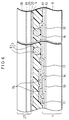
- Fig. 5 shows the structure of a two-dimensional image detector including an active matrix substrate 22 as another example of the structure of the active matrix substrate.
- the structure of the active matrix substrate 22 is similar to that of the active matrix substrate 1 shown in Fig. 2. Therefore, the members having the same function as those shown in Fig. 2 will be designated by the same reference numbers, and their descriptions will be omitted.
- the active matrix substrate 22 includes a glass substrate 9 on which XY matrix-form electrode wiring formed by gate electrodes 10 and source electrodes 11, the charge storage capacitors 4, the TFTs 5, etc. are formed.
- the glass substrate 9 is a no-alkali glass substrate (for example, #7059 or #1737 manufactured by Corning Inc.) on which the gate electrode 10 made of a metal film of Ta, etc. is formed.
- the gate electrode 10 is obtained by depositing a film of Ta, etc. to have a thickness of about 3000 ⁇ by sputter evaporation, and then patterning the film to have a desired pattern.
- a Cs electrode 12 of the charge storage capacitor 4 is formed.
- an insulating film 13 made of SiN x or SiO x is deposited to have a thickness of about 3500 ⁇ by the CVD method.
- the insulating film 13 functions as a gate insulating film of the TFT 5 and as a dielectric layer between the electrodes of the charge storage capacitor 4. Together with SiN x or SiO x , an anodic oxidation coating produced by anodic oxidation of the gate electrode 10 and the Cs electrode 12 may be used for forming the insulating film 13.
- an a-Si film (i layer) 14 functioning as a channel section of the TFT 5 and an a-Si film (n + layer) 15 for bringing the source electrode 11 and a drain electrode 23 (to be described later) into contact with each other are deposited by the CVD method to have thicknesses of about 1000 ⁇ and 400 ⁇ , respectively, and then patterned to have desired patterns. Thereafter, the source electrode 11 and the drain electrode 23 made of metal films of Ta or Al are formed. The source electrode 11 and the drain electrode 23 are obtained by depositing the metal films to have a thickness of 3000 ⁇ by sputter evaporation, and patterning them to have desired patterns.
- an insulating protective film 24 having a thickness of about 3 ⁇ m.
- an organic insulating film having photosensitivity for example, an acrylic resin is used.
- the insulating protective film 24 is then patterned by a photolithography technique, and a throughhole 25 is formed at a specific location.
- a pixel electrode 26 made of a conductive film such as Al, Ti, and ITO is deposited on the insulating protective film 24 by sputter evaporation to have a thickness of about 2000 ⁇ , and patterned to have a desired pattern.
- the pixel electrode 26 and the drain electrode 23 of the TFT 5 are electrically connected through the throughhole 23 provided in the insulating protective film 24.
- the two-dimensional image detector according to the present embodiment is completed in the same manner as in the first embodiment. Namely, the active matrix substrate 22 having the above structure is adhered to an opposing substrate 2 including as a support substrate a semiconductor substrate 18 having photoconductivity with respect to X-rays with an anisotropic conductive material 3.
- This two-dimensional image detector operates on the same basic principle as that described in the first embodiment, though the structures of the active matrix substrates are slightly different.
- the two-dimensional image detector in accordance with the present embodiment includes the active matrix substrate 22 whose surface is substantially entirely covered with the insulating protective film 24 made of an organic insulating film. Therefore, the insulating protective film 24 makes the base substrate (the glass substrate 9 with the XY matrix-form electrode wiring and the TFTs 5 formed thereon) flat.
- the surface of the active matrix substrate 1 has projections and depressions of about 1 ⁇ m because of the TFTs 5 and the XY matrix-form electrode wiring.
- the surface of the base substrate is made flat by the insulating protective film 24 as shown in Fig. 5, thereby reducing the projections and the depressions on the surface of the active matrix substrate 22 to those of about 0.2 ⁇ m.
- the pixel electrode 26 can be formed on the TFT 5 and the electrode wiring in an overlapped manner, thereby securing a large margin in designing the pixel electrode 26.
- the opposing substrate used in the two-dimensional image detector according to the present invention is not limited to the structure shown in Fig. 2, and an opposing substrate having another structure can be used.
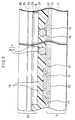
- Fig. 6 shows the structure of a two-dimensional image detector including an opposing substrate 27 as another example of the structure of the opposing substrate.
- the structure of the opposing substrate 27 is similar to that of the opposing substrate 2 shown in Fig. 2. Therefore, the members having the same function as those shown in Fig. 2 will be designated by the same reference numbers, and their descriptions will be omitted.
- the opposing substrate 27 mainly includes a support substrate 28 and a semiconductor film (semiconductor layer) 29 to be deposited on the support substrate 28.
- the support substrate 28 must be a substrate having X-ray permeability, made of glass, ceramic, silicon, etc. A glass substrate having excellent permeability with respect to both X-rays and visible light, and a thickness ranging from about 0.7 to 1.1 mm is used here. Most X-rays at 40 to 100 keV can permeate the support substrate 28 like this.
- a top electrode 19 is formed by a metal such as Ti and Ag on one surface of the semiconductor substrate 18, particularly on the almost entire surface.
- a metal such as Ti and Ag
- an ITO electrode which is transparent with respect to visible light is used as the top electrode 19.
- a polycrystalline film made of CdTe or CdZnTe is formed by the MOCVD method to have a thickness of about 0.5 mm.
- the MOCVD method is suitable for depositing the film on a large-area substrate.
- the film deposition can be performed at a deposition temperature ranging from 400 to 500°C by using the raw materials: organic cadmiums (dimethyl cadmium [DMCd], etc.), organic telluriums (diethyl tellurium [DETe], diisopropyl tellurium [DiPTe], etc.), organic zincs (diethyl zinc [DEZn], diisopropyl zinc [DiPZn], dimethyl zinc [DMZn], etc.).
- organic cadmiums dimethyl cadmium [DMCd], etc.
- organic telluriums diethyl tellurium [DETe], diisopropyl tellurium [DiPTe], etc.
- organic zincs diethyl zinc [DEZn], diisopropyl zinc [DiPZn], dimethyl zinc [DMZn], etc.
- connection electrode 6 is formed by depositing a film of a metal such as Ta and Al to have a thickness of about 2000 ⁇ , and patterning it to have a desired pattern.
- the connection electrode 6 is preferably formed at the position corresponding to the pixel electrode 16 formed on the active matrix substrate 1.
- the two-dimensional image detector in accordance with the present embodiment is completed by adhering the opposing substrate 27 arranged as above to the active matrix substrate 1 with an anisotropic conductive adhesive agent 3.
- This two-dimensional image detector operates on the same basic principle as that described in the first embodiment, though the structures of the opposing substrates are slightly different. Needless to say, it is also possible to arrange the opposing substrate 27 to be adhered to the active matrix substrate 22 in the second embodiment.
- the opposing substrate 27 having the above structure since the semiconductor film 29 with photoconductivity is formed on the support substrate 28, the physical strength can be increased compared with the opposing substrate 2 described in the first embodiment. As a result, the opposing substrate 27 becomes less likely to crack when adhering the active matrix substrate 1 and the opposing substrate 27, thereby increasing the process margin.
- this two-dimensional image detector is limited to detecting images by X-rays, it is also possible to use a X-ray permeable metal substrate, and make it function as the support substrate 28 and the top electrode 19.
- the opposing substrate used in the two-dimensional image detector according to the present invention is not limited to the structures shown in Figs. 2 and 6, and an opposing substrate having another structure can be used.
- Fig. 7 shows the structure of a two-dimensional image detector including an opposing substrate 30 as another example of the structure of the opposing substrate.
- the structure of the opposing substrate 30 is similar to that of the opposing substrate 27 shown in Fig. 6. Therefore, the members having the same function as those shown in Fig. 6 will be designated by the same reference numbers and their descriptions will be omitted.
- the opposing substrate 30 has basically the same structure as the opposing substrate 27 shown in the third embodiment, and further includes a protrusion electrode 31 on a connection electrode 6. Namely, the protrusion electrode 31 is formed in correspondence with each of the plurality of pixel electrodes 16 on an active matrix substrate 1.
- the protrusion electrode 31 is formed on the connection electrode 6 by a metal such as Au, Cu, In, and solder, having a height ranging from a few micrometers to several tens micrometers, by the plating method or the stud bumping method. Alternatively, these metals may be laminated to form the protrusion electrode 31.
- the protrusion electrode 31 may have other structures as below.
- the connection electrode 6 may be formed by the metals such as Au, Cu, In, and solder, having a height ranging from a few micrometers to several tens micrometers, or formed by laminating these metals, and arranged to function as the protrusion electrode 31.
- the protrusion electrode 31 can be formed as follows. Projections and depressions ranging from a few micrometers to several tens micrometers are formed at connection parts, i.e., locations where the connection electrodes 6 are to be formed, of the front surface (the surface facing the active matrix substrate 1) of the semiconductor film 29 made of CdTe, CdZnTe, etc. by photolithography or etching, and then the connection electrode 6 may be formed on the projection by the process shown in the third embodiment and arranged to function as the protrusion electrode 31.
- the two-dimensional image detector according to the present embodiment is completed by adhering the opposing substrate 30 including the protrusion electrode 31 arranged as above to the active matrix substrate 1 with an anisotropic conductive adhesive agent 3.
- the opposing substrate 30 for example, a structure in which the protrusion electrodes 31 are formed on the opposing substrate 27 shown in the third embodiment is illustrated.
- other arrangements of the opposing substrate 30 are acceptable.
- a structure in which the protrusion electrodes 31 are formed on the opposing substrate 2 shown in the first embodiment may be used.
- the protrusion electrode 31 may be formed on the pixel electrode 16 of the active matrix substrate 1, and this arrangement can achieve the same effect as the above-mentioned example.
- the two-dimensional image detector for detecting images by X-rays (radiation).
- the semiconductor the semiconductor substrate 18 or the semiconductor film 29
- the two-dimensional image detector can be also used for detecting images by visible light and infrared light.
- a transparent electrode made of ITO, etc. which visible light and infrared light can permeate, is used.
- the thickness of the semiconductor is optimized in accordance with the absorption efficiency of visible light and infrared light.
- the TFT 5 is used as the switching element for use in the active matrix substrate 1 (or the active matrix substrate 22).
- Other elements available here as the switching element are a two-terminal element such as a MIM (Metal-Insulator-Metal) and a varistor, and a switching element produced by combining diodes such as a diode ring and a back-to-back diode.
- the basic structure of the present invention is such that the active matrix substrate and the photoconductor layer are formed on different substrates and then adhered to each other. Therefore, in addition to the above-mentioned effects, the present invention produces such an effect that overall yield is improved compared with the structure where the photoconductor layer is directly formed on the active matrix substrate.
- the reason for this is as follows. In the conventional structure where the photoconductor layer is directly laminated on the active matrix substrate, when a deficiency exists in the photoconductor layer, the active matrix substrate below the photoconductor layer is wasted. In contrast, in the present invention, the active matrix substrate and the opposing substrate, having no deficiencies, can be chosen and combined.
- the present invention is not limited to the two-dimensional image detector using the above-mentioned photoconductor material and sensor structure, and can be applied to a two-dimensional image detector using another photoconductor material and sensor structure.
- a photoconductor layer polycrystal like CdTe and CdZnTe having excellent sensitivity to X-rays
- other semiconductor materials such as a-Se and a-Si can be used as the photoconductor layer.
- the opposing substrate may be arranged to use a combination of a conversion layer (for example, CsI) for converting X-rays to visible light and a visible-light sensor.
- a conversion layer for example, CsI
- the two-dimensional image detector of the present invention is based on a two-dimensional image detector including:
- the semiconductor layer is preferably arranged to have sensitivity to radiation.
- the semiconductor layer is preferably made of a compound semiconductor represented by CdTe or CdZnTe.
- the anisotropic conductive material is preferably an anisotropic conductive adhesive agent produced by dispersing conductive particles in an insulating adhesive agent.
- the two-dimensional image detector is arranged so that the active matrix substrate including the pixel array layer is connected to the opposing substrate including the electrode section and the semiconductor layer with the anisotropic conductive material, the active matrix substrate and the opposing substrate can be produced individually. It is thus possible to use, for the semiconductor layer, the material which could not be conventionally used because of the relation between the film deposition temperature of the semiconductor layer and the heat resistance of the switching element on the active matrix substrate. In addition, by arranging the semiconductor layer to have sensitivity to radiation, the two-dimensional image detector for detecting the radiation image can be realized.
- the compound semiconductor like CdTe or CdZnTe having higher sensitivity (S/N ratio) to radiation such as X-rays than a-Se used conventionally it is possible to improve the response of the two-dimensional image detector compared with the conventional one.
- the voltage applied to the electrode section can be set lower than the conventional value. It is thus possible to omit the dielectric layer which were conventionally provided between the semiconductor layer and the electrode section for protection from the high voltage. Since the conventional structure where the dielectric layer is provided between the semiconductor layer and the electrode section requires a sequence for removing the charges remaining in the dielectric layer every frame, only static images can be detected. However, since the two-dimensional image detector of the present invention can omit the dielectric layer, dynamic images can be detected as well.
- the two substrates i.e., the active matrix substrate and the opposing substrate are connected to each other with the anisotropic conductive material. Therefore, the pixels of the active matrix substrate are electrically insulated from each other, and the pixel electrodes on the active matrix substrate and the semiconductor layer of the opposing substrate can be electrically and physically connected to each other without causing crosstalk between the adjacent pixels.
- the anisotropic conductive adhesive agent produced by dispersing the conductive particles in the insulating adhesive agent can be used.
- the anisotropic conductive adhesive agent for example, by filling the anisotropic conductive adhesive agent between the upper and lower substrates and pressing the substrates so as to adhere the two substrates, the two facing substrates can be brought into conduction by the conductive particles, and the adjacent electrodes can be insulated from each other. It is thus possible to obtain satisfactory anisotropic conduction characteristics.
- a paste-form adhesive agent can be used as the anisotropic conductive adhesive agent. This adhesive agent can be easily applied to even a large-area substrate by the screen printing method, etc.
- a film-form adhesive agent can be also used as the anisotropic conductive adhesive agent.
- the film-form adhesive agent having excellent uniformity in thickness as the anisotropic conductive adhesive agent, a uniform thickness of the adhesive agent can be easily realized even when adhering the large-area substrates.
- thermosetting-type adhesive agent with excellent reliability in the heat resistance, the adhesive property, etc. as the anisotropic conductive adhesive agent, a highly-reliable two-dimensional image detector can be realized.
- thermoplastic-type adhesive agent can be also used as the anisotropic conductive adhesive agent.
- the use of the thermoplastic-type adhesive agent as the anisotropic conductive adhesive agent produces the following effect. Namely, when a deficiency is found in either the active matrix substrate or the opposing substrate after the two substrates are adhered by performing the heat treatment, the substrates once adhered can be separated by softening the adhesive agent by performing the heat treatment again. In addition, reworking can be easily performed.
- a photo-curing-type adhesive agent can be used as the anisotropic conductive adhesive agent.
- the pixel electrode is preferably a transparent electrode. Since the photo-curing-type agent is used as the anisotropic conductive adhesive agent, no heat treatment is required when adhering the two substrates, i.e., the active matrix substrate and the opposing substrate. Therefore, when adhering the active matrix substrate and the opposing substrate having relatively large areas, even if the two substrates have different thermal expansion coefficients, no heat treatment is necessary. Therefore, warpage of the substrates and separation of adhered surfaces are not caused by the difference in the degree of thermal expansion.
- the photo-curing-type anisotropic conductive adhesive agent can be irradiated with light incident from the active matrix substrate side through the pixel electrode.
- connection electrodes are formed on the surface of the semiconductor layer of the opposing substrate in correspondence with a plurality of pixel electrodes formed on the active matrix substrate.
- the pixels of the semiconductor on the opposing substrate are electrically separated from each other by the plurality of connection electrodes in correspondence with the plurality of pixel electrodes formed on the active matrix substrate. Therefore, the charges generated in the semiconductor by incidence of radiation and light beams are collected by only the connection electrode corresponding to the incidence location, and the charges do not move to the surrounding pixels. As a result, the electrical crosstalk is prevented.
- each pixel electrode has a smaller area than the connection electrode.
- the connection electrode having a maximum size within each pixel on the semiconductor layer side of the opposing substrate, the charges generated in the semiconductor by incidence of X-rays and light beams can be efficiently collected.
- the pixel electrode of the active matrix substrate side to have a smaller size than the connection electrode, even if the active matrix substrate and the opposing substrate are not accurately aligned when adhering the two substrates, the electric crosstalk between the adjacent pixels can be prevented.
- a plurality of protrusion electrodes may be formed on the connection surface of at least one of the active matrix substrate and the opposing substrate in correspondence with a plurality of pixel electrodes formed on the active matrix substrate.
- a crystalline semiconductor substrate obtained by the Bridgeman method, the gradient freezing method, the travel heating method, etc. can be used as the semiconductor layer.
- the opposing substrate can be also arranged so that a substrate which light and radiation to be detected can permeate is provided as the support substrate, and the semiconductor layer having photoconductivity is formed on the support substrate. Since the opposing substrate is arranged to include the substrate which light and radiation to be detected can permeate as the support substrate, and the semiconductor layer with photoconductivity formed on the support substrate, the strength of the opposing substrate can be increased.
- a process for manufacturing a two-dimensional image detector of the present invention is based on a process for manufacturing a two-dimensional image detector including:
- the active matrix substrate including the pixel array layer is produced in the first step, and the opposing substrate including the electrode section and the semiconductor layer is produced in the second step.
- the individually produced substrates are then connected to each other with the anisotropic conductive material in the third step. Therefore, unlike the conventional process, it is unnecessary to newly form the semiconductor layer on the substrate where the pixel array layer is already formed.
- the material which could not be conventionally used for example, the compound semiconductor like CdTe or CdZnTe can be used for the semiconductor layer.
- the above semiconductor material has higher sensitivity (S/N ratio) to radiation such as X-rays than a-Se which was conventionally used, when the compound semiconductor like CdTe or CdZnTe is used for the semiconductor layer, the response of the two-dimensional image detector can be improved, and dynamic images can be detected as well.
- the anisotropic conductive adhesive agent including the conductive particles dispersed in the adhesive agent is used as the anisotropic conductive material, and after applying or transferring this anisotropic conductive adhesive agent to the surface of at least one of the active matrix substrate and the opposing substrate, the two substrates are adhered to each other.
- the anisotropic conductive adhesive agent is used as the anisotropic conductive material, and the active matrix substrate and the opposing substrate are adhered with the anisotropic conductive adhesive agent. Consequently, even when adhering the active matrix substrate and the opposing substrate having the large areas, the anisotropic conductive adhesive agent can be easily applied or transferred, and thus the two substrates can be easily adhered to each other.
- the anisotropic conductive adhesive agent is applied or transferred to have a thickness substantially equal to the diameter of the conductive particle. Therefore, even when adhering substantially-flat surfaces of the substrates, it is possible to minimize the flow of the excessive adhesive agent and to obtain satisfactory anisotropic conductivity.
- thermosetting-type anisotropic conductive adhesive agent or the thermoplastic-type anisotropic conductive adhesive agent is used as the anisotropic conductive adhesive agent, and the active matrix substrate and the opposing substrate are adhered to each other by passing them between the heat rollers.
- the press force is not required to be applied to the entire surface of the substrate.
- the large-scale hydraulic press device, etc. are not required, and a relatively small-scale press device can be used.
- the step of adhering the two substrates and the devices used in the adhering step can be simplified.
- thermosetting-type anisotropic conductive adhesive agent or the thermoplastic-type anisotropic conductive adhesive agent can be used as the anisotropic conductive adhesive agent, and the active matrix substrate and the opposing substrate can be adhered to each other by thermocompression bonding using the press device.
- thermocompression bonding using the press device
- a general thermal press device can be used in the step of adhering the substrates.
- the press device can be replaced by the autoclave device. Therefore, even when adhering the active matrix substrate and the opposing substrate having the large areas, a uniform pressure can be obtained.
- the photo-curing-type anisotropic conductive adhesive agent can be used as the anisotropic conductive adhesive agent, and the active matrix substrate and the opposing substrate can be brought into contact with and then adhered to each other by irradiation of light from the active matrix substrate.
- the active matrix substrate and the opposing substrate can be adhered to each other without requiring heat treatment.
- the active matrix substrate and the opposing substrate can be adhered to each other without requiring heat treatment.
Landscapes
- Engineering & Computer Science (AREA)
- Power Engineering (AREA)
- Physics & Mathematics (AREA)
- General Physics & Mathematics (AREA)
- Electromagnetism (AREA)
- Condensed Matter Physics & Semiconductors (AREA)
- Health & Medical Sciences (AREA)
- Toxicology (AREA)
- Computer Hardware Design (AREA)
- Microelectronics & Electronic Packaging (AREA)
- Solid State Image Pick-Up Elements (AREA)
- Measurement Of Radiation (AREA)
- Light Receiving Elements (AREA)
Applications Claiming Priority (4)
| Application Number | Priority Date | Filing Date | Title |
|---|---|---|---|
| JP906798 | 1998-01-20 | ||
| JP906798 | 1998-01-20 | ||
| JP13398698A JP3649907B2 (ja) | 1998-01-20 | 1998-05-15 | 二次元画像検出器およびその製造方法 |
| JP13398698 | 1998-05-15 |
Publications (2)
| Publication Number | Publication Date |
|---|---|
| EP0930657A1 true EP0930657A1 (de) | 1999-07-21 |
| EP0930657B1 EP0930657B1 (de) | 2006-05-17 |
Family
ID=26343719
Family Applications (1)
| Application Number | Title | Priority Date | Filing Date |
|---|---|---|---|
| EP99100884A Expired - Lifetime EP0930657B1 (de) | 1998-01-20 | 1999-01-19 | Zweidimensionaler Bilddetektor und Verfahren zu dessen Herstellung |
Country Status (5)
| Country | Link |
|---|---|
| US (1) | US6262408B1 (de) |
| EP (1) | EP0930657B1 (de) |
| JP (1) | JP3649907B2 (de) |
| CN (1) | CN1174491C (de) |
| DE (1) | DE69931287T2 (de) |
Cited By (5)
| Publication number | Priority date | Publication date | Assignee | Title |
|---|---|---|---|---|
| EP1207559A2 (de) * | 2000-10-26 | 2002-05-22 | Canon Kabushiki Kaisha | Strahlungsdetektorvorrichtung, Verfahren zur Herstellung einer Vorrichtung, und radiographisches Abbildungssystem |
| FR2833410A1 (fr) * | 2001-12-10 | 2003-06-13 | Commissariat Energie Atomique | Procede de realisation d'un dispositif d'imagerie |
| WO2004097938A1 (en) | 2003-03-27 | 2004-11-11 | Ajat Oy, Ltd. | Conductive adhesive bonded semiconductor substrates for radiation imaging devices |
| EP1207560A3 (de) * | 2000-11-01 | 2006-06-14 | Canon Kabushiki Kaisha | Anordnung zur elektromagnetischen Strahltransformation |
| DE102008025199B3 (de) * | 2008-05-27 | 2009-09-17 | Siemens Aktiengesellschaft | Strahlungsdetektor und Herstellungsverfahren sowie Strahlungserfassungseinrichtung |
Families Citing this family (53)
| Publication number | Priority date | Publication date | Assignee | Title |
|---|---|---|---|---|
| US7136452B2 (en) * | 1995-05-31 | 2006-11-14 | Goldpower Limited | Radiation imaging system, device and method for scan imaging |
| JP3976915B2 (ja) * | 1998-02-09 | 2007-09-19 | シャープ株式会社 | 二次元画像検出器およびその製造方法 |
| JP3430040B2 (ja) * | 1998-11-19 | 2003-07-28 | シャープ株式会社 | 二次元画像検出器およびその製造方法 |
| JP4036555B2 (ja) * | 1999-01-14 | 2008-01-23 | 松下電器産業株式会社 | 実装構造体の製造方法および実装構造体 |
| JP2001210813A (ja) | 2000-01-27 | 2001-08-03 | Sharp Corp | 二次元画像検出器およびその製造方法 |
| JP2001210855A (ja) | 2000-01-27 | 2001-08-03 | Sharp Corp | 二次元画像検出器 |
| JP2001313384A (ja) * | 2000-04-28 | 2001-11-09 | Shimadzu Corp | 放射線検出器 |
| JP3588053B2 (ja) * | 2001-02-07 | 2004-11-10 | シャープ株式会社 | 電磁波検出器 |
| US7038242B2 (en) * | 2001-02-28 | 2006-05-02 | Agilent Technologies, Inc. | Amorphous semiconductor open base phototransistor array |
| JP2002333848A (ja) * | 2001-05-10 | 2002-11-22 | Sharp Corp | 複合アクティブマトリクス基板、その製造方法、及び電磁波撮像装置 |
| US6828545B1 (en) * | 2001-05-15 | 2004-12-07 | Raytheon Company | Hybrid microelectronic array structure having electrically isolated supported islands, and its fabrication |
| US7009663B2 (en) | 2003-12-17 | 2006-03-07 | Planar Systems, Inc. | Integrated optical light sensitive active matrix liquid crystal display |
| US7053967B2 (en) * | 2002-05-23 | 2006-05-30 | Planar Systems, Inc. | Light sensitive display |
| US7023503B2 (en) * | 2002-02-20 | 2006-04-04 | Planar Systems, Inc. | Image sensor with photosensitive thin film transistors |
| US7408598B2 (en) | 2002-02-20 | 2008-08-05 | Planar Systems, Inc. | Light sensitive display with selected interval of light sensitive elements |
| JP4152684B2 (ja) * | 2002-07-17 | 2008-09-17 | 松下電器産業株式会社 | 受光モジュールとその製造方法 |
| KR100505355B1 (ko) * | 2002-07-22 | 2005-08-01 | 남상희 | 고해상도 디지털 엑스레이 검출용 tft 기판 |
| EP1565942B1 (de) * | 2002-11-19 | 2009-07-15 | Koninklijke Philips Electronics N.V. | Röntgenuntersuchungsgerät |
| CN1230693C (zh) * | 2002-11-26 | 2005-12-07 | 张亚美 | 小面积像素电极直接平板x-线探测器 |
| US20080084374A1 (en) | 2003-02-20 | 2008-04-10 | Planar Systems, Inc. | Light sensitive display |
| TW200417770A (en) * | 2003-03-07 | 2004-09-16 | Au Optronics Corp | Method for assembling a component of a liquid crystal display device |
| US20040246355A1 (en) * | 2003-06-06 | 2004-12-09 | Ji Ung Lee | Storage capacitor array for a solid state radiation imager |
| US7773139B2 (en) | 2004-04-16 | 2010-08-10 | Apple Inc. | Image sensor with photosensitive thin film transistors |
| US6953935B1 (en) * | 2004-05-11 | 2005-10-11 | General Electric Company | CT detector fabrication process |
| DE102004029589A1 (de) * | 2004-06-18 | 2005-12-29 | Tesa Ag | Elektrisch anisotrop leitfähiger Schmelzkleber zur Implantierung von elektrischen Modulen in einen Kartenkörper |
| JP2006269465A (ja) * | 2005-03-22 | 2006-10-05 | Fuji Photo Film Co Ltd | 画像記録媒体の製造方法 |
| JP2007214191A (ja) * | 2006-02-07 | 2007-08-23 | Sumitomo Heavy Ind Ltd | 放射線検出器および放射線検査装置 |
| JP4432949B2 (ja) * | 2006-09-15 | 2010-03-17 | パナソニック株式会社 | 電気部品の接続方法 |
| JP2008139124A (ja) * | 2006-11-30 | 2008-06-19 | Shimadzu Corp | 放射線二次元検出器 |
| US8525132B2 (en) | 2007-09-06 | 2013-09-03 | Konica Minolta Medical & Graphic, Inc. | Flat panel detector |
| DE102008013412B3 (de) * | 2008-03-10 | 2009-10-15 | Siemens Aktiengesellschaft | Herstellungsverfahren für ein Strahlungsdetektormodul und Herstellungsverfahren für einen Strahlungsdetektor |
| US8071953B2 (en) * | 2008-04-29 | 2011-12-06 | Redlen Technologies, Inc. | ACF attachment for radiation detector |
| KR101672344B1 (ko) * | 2010-05-20 | 2016-11-04 | 삼성전자주식회사 | 광센싱 회로, 상기 광센싱 회로의 구동 방법, 및 상기 광센싱 회로를 채용한 광센싱 장치 |
| JP5676155B2 (ja) * | 2010-06-23 | 2015-02-25 | 日立アロカメディカル株式会社 | 放射線検出器の製造方法、及び放射線検出器 |
| US8187912B2 (en) * | 2010-08-27 | 2012-05-29 | Primestar Solar, Inc. | Methods of forming an anisotropic conductive layer as a back contact in thin film photovoltaic devices |
| US9310923B2 (en) | 2010-12-03 | 2016-04-12 | Apple Inc. | Input device for touch sensitive devices |
| JP2012177624A (ja) * | 2011-02-25 | 2012-09-13 | Fujifilm Corp | 放射線画像検出装置及び放射線画像検出装置の製造方法 |
| US8928635B2 (en) | 2011-06-22 | 2015-01-06 | Apple Inc. | Active stylus |
| US9329703B2 (en) | 2011-06-22 | 2016-05-03 | Apple Inc. | Intelligent stylus |
| US8638320B2 (en) | 2011-06-22 | 2014-01-28 | Apple Inc. | Stylus orientation detection |
| US9176604B2 (en) | 2012-07-27 | 2015-11-03 | Apple Inc. | Stylus device |
| US9652090B2 (en) | 2012-07-27 | 2017-05-16 | Apple Inc. | Device for digital communication through capacitive coupling |
| US9557845B2 (en) | 2012-07-27 | 2017-01-31 | Apple Inc. | Input device for and method of communication with capacitive devices through frequency variation |
| CN107889344A (zh) * | 2012-08-15 | 2018-04-06 | 深圳迈辽技术转移中心有限公司 | 软性电路板装置 |
| US10048775B2 (en) | 2013-03-14 | 2018-08-14 | Apple Inc. | Stylus detection and demodulation |
| US10845901B2 (en) | 2013-07-31 | 2020-11-24 | Apple Inc. | Touch controller architecture |
| US9859316B2 (en) * | 2014-06-06 | 2018-01-02 | Sharp Kabushiki Kaisha | Semiconductor device and method for manufacturing same |
| US10067618B2 (en) | 2014-12-04 | 2018-09-04 | Apple Inc. | Coarse scan and targeted active mode scan for touch |
| EP3241041B1 (de) * | 2014-12-30 | 2020-06-17 | General Electric Company | Röntgendetektoranordnung |
| US9753151B2 (en) * | 2015-07-31 | 2017-09-05 | General Electric Company | Light guide array for pet detector fabrication methods and apparatus |
| US10474277B2 (en) | 2016-05-31 | 2019-11-12 | Apple Inc. | Position-based stylus communication |
| CN110473771B (zh) * | 2019-07-30 | 2021-04-20 | 西北工业大学 | 直接转换x射线探测材料的制备方法 |
| CN112820784B (zh) * | 2020-11-24 | 2022-11-25 | 上海航天电子通讯设备研究所 | 一种垂直背入射同面电极高功率光导开关 |
Citations (4)
| Publication number | Priority date | Publication date | Assignee | Title |
|---|---|---|---|---|
| EP0523783A1 (de) * | 1991-07-15 | 1993-01-20 | Philips Electronics Uk Limited | Bildgebender Detektor mit Wellenlängenschieber |
| EP0602475A2 (de) * | 1992-12-16 | 1994-06-22 | E.I. Du Pont De Nemours And Company | Methode und Apparat zur Gerinnung eines Röntgenbildes unter Verwendung eines Festkörper-Elementes |
| US5379336A (en) * | 1992-05-21 | 1995-01-03 | Hughes Aircraft Company | Hybridized semiconductor pixel detector arrays for use in digital radiography |
| EP0783177A1 (de) * | 1991-10-24 | 1997-07-09 | Fujitsu Limited | Verfahren zur Erzeugung eines leitenden Füllstoffes vom Mikrokapseltyp |
Family Cites Families (4)
| Publication number | Priority date | Publication date | Assignee | Title |
|---|---|---|---|---|
| CA2034118A1 (en) * | 1990-02-09 | 1991-08-10 | Nang Tri Tran | Solid state radiation detector |
| GB9301405D0 (en) * | 1993-01-25 | 1993-03-17 | Philips Electronics Uk Ltd | An image sensor |
| US6035013A (en) * | 1994-06-01 | 2000-03-07 | Simage O.Y. | Radiographic imaging devices, systems and methods |
| US5723866A (en) * | 1996-06-26 | 1998-03-03 | He Holdings, Inc. | Method for yield and performance improvement of large area radiation detectors and detectors fabricated in accordance with the method |
-
1998
- 1998-05-15 JP JP13398698A patent/JP3649907B2/ja not_active Expired - Lifetime
-
1999
- 1999-01-13 US US09/229,269 patent/US6262408B1/en not_active Expired - Lifetime
- 1999-01-19 DE DE69931287T patent/DE69931287T2/de not_active Expired - Lifetime
- 1999-01-19 EP EP99100884A patent/EP0930657B1/de not_active Expired - Lifetime
- 1999-01-20 CN CNB99101264XA patent/CN1174491C/zh not_active Expired - Fee Related
Patent Citations (5)
| Publication number | Priority date | Publication date | Assignee | Title |
|---|---|---|---|---|
| EP0523783A1 (de) * | 1991-07-15 | 1993-01-20 | Philips Electronics Uk Limited | Bildgebender Detektor mit Wellenlängenschieber |
| EP0783177A1 (de) * | 1991-10-24 | 1997-07-09 | Fujitsu Limited | Verfahren zur Erzeugung eines leitenden Füllstoffes vom Mikrokapseltyp |
| US5379336A (en) * | 1992-05-21 | 1995-01-03 | Hughes Aircraft Company | Hybridized semiconductor pixel detector arrays for use in digital radiography |
| EP0602475A2 (de) * | 1992-12-16 | 1994-06-22 | E.I. Du Pont De Nemours And Company | Methode und Apparat zur Gerinnung eines Röntgenbildes unter Verwendung eines Festkörper-Elementes |
| JPH06342098A (ja) * | 1992-12-16 | 1994-12-13 | E I Du Pont De Nemours & Co | ソリッド・ステート・デバイスを用いたx線イメージ捕獲エレメントおよび方法 |
Cited By (11)
| Publication number | Priority date | Publication date | Assignee | Title |
|---|---|---|---|---|
| EP1207559A2 (de) * | 2000-10-26 | 2002-05-22 | Canon Kabushiki Kaisha | Strahlungsdetektorvorrichtung, Verfahren zur Herstellung einer Vorrichtung, und radiographisches Abbildungssystem |
| EP1207559A3 (de) * | 2000-10-26 | 2005-10-12 | Canon Kabushiki Kaisha | Strahlungsdetektorvorrichtung, Verfahren zur Herstellung einer Vorrichtung, und radiographisches Abbildungssystem |
| EP1207560A3 (de) * | 2000-11-01 | 2006-06-14 | Canon Kabushiki Kaisha | Anordnung zur elektromagnetischen Strahltransformation |
| FR2833410A1 (fr) * | 2001-12-10 | 2003-06-13 | Commissariat Energie Atomique | Procede de realisation d'un dispositif d'imagerie |
| WO2003050875A2 (fr) * | 2001-12-10 | 2003-06-19 | Commissariat A L'energie Atomique | Procede de realisation d'un dispositif d'imagerie |
| WO2003050875A3 (fr) * | 2001-12-10 | 2003-12-11 | Commissariat Energie Atomique | Procede de realisation d'un dispositif d'imagerie |
| US7713759B2 (en) | 2001-12-10 | 2010-05-11 | Commissariat A L'energie Atomique | Method for producing an imaging device |
| WO2004097938A1 (en) | 2003-03-27 | 2004-11-11 | Ajat Oy, Ltd. | Conductive adhesive bonded semiconductor substrates for radiation imaging devices |
| EP1606843A1 (de) * | 2003-03-27 | 2005-12-21 | Ajat OY, LTD. | Leitfähige klebende gebondete halbleitersubstrate für strahlungsabbildungseinrichtungen |
| EP1606843A4 (de) * | 2003-03-27 | 2007-02-21 | Ajat Oy Ltd | Leitfähige klebende gebondete halbleitersubstrate für strahlungsabbildungseinrichtungen |
| DE102008025199B3 (de) * | 2008-05-27 | 2009-09-17 | Siemens Aktiengesellschaft | Strahlungsdetektor und Herstellungsverfahren sowie Strahlungserfassungseinrichtung |
Also Published As
| Publication number | Publication date |
|---|---|
| US6262408B1 (en) | 2001-07-17 |
| CN1174491C (zh) | 2004-11-03 |
| CN1224244A (zh) | 1999-07-28 |
| DE69931287T2 (de) | 2007-02-01 |
| DE69931287D1 (de) | 2006-06-22 |
| JPH11274448A (ja) | 1999-10-08 |
| EP0930657B1 (de) | 2006-05-17 |
| JP3649907B2 (ja) | 2005-05-18 |
Similar Documents
| Publication | Publication Date | Title |
|---|---|---|
| US6262408B1 (en) | Two-dimensional image detector and process for manufacturing the same | |
| US6342700B1 (en) | Two-dimensional image detector | |
| JP3976915B2 (ja) | 二次元画像検出器およびその製造方法 | |
| JP3430040B2 (ja) | 二次元画像検出器およびその製造方法 | |
| JP3847494B2 (ja) | 二次元画像検出器の製造方法 | |
| JP3432770B2 (ja) | 二次元画像検出器の製造方法 | |
| JP3549039B2 (ja) | 二次元画像検出器 | |
| US6340818B1 (en) | Two-dimensional image detector | |
| US6825473B2 (en) | Radiation detecting apparatus, methods of producing apparatus, and radiographic imaging system | |
| JP4205134B2 (ja) | 二次元画像検出器 | |
| CA2482279A1 (en) | Radiation detector | |
| Zhao et al. | Digital radiology using self-scanned readout of amorphous selenium: Design considerations for mammography | |
| US6603106B2 (en) | Two-dimensional image detector and fabrication method of the same | |
| JP4202315B2 (ja) | 二次元画像検出器 | |
| JP3587991B2 (ja) | 二次元画像検出器およびその製造方法 | |
| JP3798145B2 (ja) | 二次元画像検出器およびその製造方法 | |
| JP2001091656A (ja) | 二次元画像検出器 | |
| JP3437461B2 (ja) | 二次元画像検出器 | |
| JP2003234461A (ja) | 二次元画像検出器 | |
| JP3670161B2 (ja) | 二次元画像検出器 | |
| JPH11295144A (ja) | 二次元画像検出器およびその製造方法 | |
| JPH11274453A (ja) | 二次元画像検出器およびその製造方法 | |
| JP2006303070A (ja) | 二次元画像検出器およびその製造方法 | |
| JPH11297977A (ja) | 二次元画像検出器 |
Legal Events
| Date | Code | Title | Description |
|---|---|---|---|
| PUAI | Public reference made under article 153(3) epc to a published international application that has entered the european phase |
Free format text: ORIGINAL CODE: 0009012 |
|
| AK | Designated contracting states |
Kind code of ref document: A1 Designated state(s): DE FR NL |
|
| AX | Request for extension of the european patent |
Free format text: AL;LT;LV;MK;RO;SI |
|
| 17P | Request for examination filed |
Effective date: 19990817 |
|
| AKX | Designation fees paid |
Free format text: DE FR NL |
|
| 17Q | First examination report despatched |
Effective date: 20031001 |
|
| GRAP | Despatch of communication of intention to grant a patent |
Free format text: ORIGINAL CODE: EPIDOSNIGR1 |
|
| GRAS | Grant fee paid |
Free format text: ORIGINAL CODE: EPIDOSNIGR3 |
|
| GRAA | (expected) grant |
Free format text: ORIGINAL CODE: 0009210 |
|
| AK | Designated contracting states |
Kind code of ref document: B1 Designated state(s): DE FR NL |
|
| REF | Corresponds to: |
Ref document number: 69931287 Country of ref document: DE Date of ref document: 20060622 Kind code of ref document: P |
|
| ET | Fr: translation filed | ||
| PLBE | No opposition filed within time limit |
Free format text: ORIGINAL CODE: 0009261 |
|
| STAA | Information on the status of an ep patent application or granted ep patent |
Free format text: STATUS: NO OPPOSITION FILED WITHIN TIME LIMIT |
|
| 26N | No opposition filed |
Effective date: 20070220 |
|
| REG | Reference to a national code |
Ref country code: FR Ref legal event code: PLFP Year of fee payment: 17 |
|
| PGFP | Annual fee paid to national office [announced via postgrant information from national office to epo] |
Ref country code: NL Payment date: 20141210 Year of fee payment: 17 |
|
| PGFP | Annual fee paid to national office [announced via postgrant information from national office to epo] |
Ref country code: DE Payment date: 20150113 Year of fee payment: 17 |
|
| PGFP | Annual fee paid to national office [announced via postgrant information from national office to epo] |
Ref country code: FR Payment date: 20150108 Year of fee payment: 17 |
|
| REG | Reference to a national code |
Ref country code: DE Ref legal event code: R119 Ref document number: 69931287 Country of ref document: DE |
|
| REG | Reference to a national code |
Ref country code: NL Ref legal event code: MM Effective date: 20160201 |
|
| REG | Reference to a national code |
Ref country code: FR Ref legal event code: ST Effective date: 20160930 |
|
| PG25 | Lapsed in a contracting state [announced via postgrant information from national office to epo] |
Ref country code: DE Free format text: LAPSE BECAUSE OF NON-PAYMENT OF DUE FEES Effective date: 20160802 |
|
| PG25 | Lapsed in a contracting state [announced via postgrant information from national office to epo] |
Ref country code: FR Free format text: LAPSE BECAUSE OF NON-PAYMENT OF DUE FEES Effective date: 20160201 Ref country code: NL Free format text: LAPSE BECAUSE OF NON-PAYMENT OF DUE FEES Effective date: 20160201 |