EP0926401A2 - Dispositif d'alimentention de pression hydraulique pour transmission véhiculaire - Google Patents
Dispositif d'alimentention de pression hydraulique pour transmission véhiculaire Download PDFInfo
- Publication number
- EP0926401A2 EP0926401A2 EP98124592A EP98124592A EP0926401A2 EP 0926401 A2 EP0926401 A2 EP 0926401A2 EP 98124592 A EP98124592 A EP 98124592A EP 98124592 A EP98124592 A EP 98124592A EP 0926401 A2 EP0926401 A2 EP 0926401A2
- Authority
- EP
- European Patent Office
- Prior art keywords
- motor
- drive ratio
- oil pressure
- automatic transmission
- rotation speed
- Prior art date
- Legal status (The legal status is an assumption and is not a legal conclusion. Google has not performed a legal analysis and makes no representation as to the accuracy of the status listed.)
- Withdrawn
Links
Images


Classifications
-
- B—PERFORMING OPERATIONS; TRANSPORTING
- B60—VEHICLES IN GENERAL
- B60W—CONJOINT CONTROL OF VEHICLE SUB-UNITS OF DIFFERENT TYPE OR DIFFERENT FUNCTION; CONTROL SYSTEMS SPECIALLY ADAPTED FOR HYBRID VEHICLES; ROAD VEHICLE DRIVE CONTROL SYSTEMS FOR PURPOSES NOT RELATED TO THE CONTROL OF A PARTICULAR SUB-UNIT
- B60W20/00—Control systems specially adapted for hybrid vehicles
-
- B—PERFORMING OPERATIONS; TRANSPORTING
- B60—VEHICLES IN GENERAL
- B60K—ARRANGEMENT OR MOUNTING OF PROPULSION UNITS OR OF TRANSMISSIONS IN VEHICLES; ARRANGEMENT OR MOUNTING OF PLURAL DIVERSE PRIME-MOVERS IN VEHICLES; AUXILIARY DRIVES FOR VEHICLES; INSTRUMENTATION OR DASHBOARDS FOR VEHICLES; ARRANGEMENTS IN CONNECTION WITH COOLING, AIR INTAKE, GAS EXHAUST OR FUEL SUPPLY OF PROPULSION UNITS IN VEHICLES
- B60K6/00—Arrangement or mounting of plural diverse prime-movers for mutual or common propulsion, e.g. hybrid propulsion systems comprising electric motors and internal combustion engines
- B60K6/20—Arrangement or mounting of plural diverse prime-movers for mutual or common propulsion, e.g. hybrid propulsion systems comprising electric motors and internal combustion engines the prime-movers consisting of electric motors and internal combustion engines, e.g. HEVs
- B60K6/42—Arrangement or mounting of plural diverse prime-movers for mutual or common propulsion, e.g. hybrid propulsion systems comprising electric motors and internal combustion engines the prime-movers consisting of electric motors and internal combustion engines, e.g. HEVs characterised by the architecture of the hybrid electric vehicle
- B60K6/48—Parallel type
-
- B—PERFORMING OPERATIONS; TRANSPORTING
- B60—VEHICLES IN GENERAL
- B60K—ARRANGEMENT OR MOUNTING OF PROPULSION UNITS OR OF TRANSMISSIONS IN VEHICLES; ARRANGEMENT OR MOUNTING OF PLURAL DIVERSE PRIME-MOVERS IN VEHICLES; AUXILIARY DRIVES FOR VEHICLES; INSTRUMENTATION OR DASHBOARDS FOR VEHICLES; ARRANGEMENTS IN CONNECTION WITH COOLING, AIR INTAKE, GAS EXHAUST OR FUEL SUPPLY OF PROPULSION UNITS IN VEHICLES
- B60K6/00—Arrangement or mounting of plural diverse prime-movers for mutual or common propulsion, e.g. hybrid propulsion systems comprising electric motors and internal combustion engines
- B60K6/20—Arrangement or mounting of plural diverse prime-movers for mutual or common propulsion, e.g. hybrid propulsion systems comprising electric motors and internal combustion engines the prime-movers consisting of electric motors and internal combustion engines, e.g. HEVs
- B60K6/50—Architecture of the driveline characterised by arrangement or kind of transmission units
- B60K6/54—Transmission for changing ratio
- B60K6/543—Transmission for changing ratio the transmission being a continuously variable transmission
-
- B—PERFORMING OPERATIONS; TRANSPORTING
- B60—VEHICLES IN GENERAL
- B60W—CONJOINT CONTROL OF VEHICLE SUB-UNITS OF DIFFERENT TYPE OR DIFFERENT FUNCTION; CONTROL SYSTEMS SPECIALLY ADAPTED FOR HYBRID VEHICLES; ROAD VEHICLE DRIVE CONTROL SYSTEMS FOR PURPOSES NOT RELATED TO THE CONTROL OF A PARTICULAR SUB-UNIT
- B60W10/00—Conjoint control of vehicle sub-units of different type or different function
- B60W10/04—Conjoint control of vehicle sub-units of different type or different function including control of propulsion units
- B60W10/08—Conjoint control of vehicle sub-units of different type or different function including control of propulsion units including control of electric propulsion units, e.g. motors or generators
-
- B—PERFORMING OPERATIONS; TRANSPORTING
- B60—VEHICLES IN GENERAL
- B60W—CONJOINT CONTROL OF VEHICLE SUB-UNITS OF DIFFERENT TYPE OR DIFFERENT FUNCTION; CONTROL SYSTEMS SPECIALLY ADAPTED FOR HYBRID VEHICLES; ROAD VEHICLE DRIVE CONTROL SYSTEMS FOR PURPOSES NOT RELATED TO THE CONTROL OF A PARTICULAR SUB-UNIT
- B60W10/00—Conjoint control of vehicle sub-units of different type or different function
- B60W10/10—Conjoint control of vehicle sub-units of different type or different function including control of change-speed gearings
-
- B—PERFORMING OPERATIONS; TRANSPORTING
- B60—VEHICLES IN GENERAL
- B60W—CONJOINT CONTROL OF VEHICLE SUB-UNITS OF DIFFERENT TYPE OR DIFFERENT FUNCTION; CONTROL SYSTEMS SPECIALLY ADAPTED FOR HYBRID VEHICLES; ROAD VEHICLE DRIVE CONTROL SYSTEMS FOR PURPOSES NOT RELATED TO THE CONTROL OF A PARTICULAR SUB-UNIT
- B60W10/00—Conjoint control of vehicle sub-units of different type or different function
- B60W10/30—Conjoint control of vehicle sub-units of different type or different function including control of auxiliary equipment, e.g. air-conditioning compressors or oil pumps
-
- F—MECHANICAL ENGINEERING; LIGHTING; HEATING; WEAPONS; BLASTING
- F16—ENGINEERING ELEMENTS AND UNITS; GENERAL MEASURES FOR PRODUCING AND MAINTAINING EFFECTIVE FUNCTIONING OF MACHINES OR INSTALLATIONS; THERMAL INSULATION IN GENERAL
- F16H—GEARING
- F16H61/00—Control functions within control units of change-speed- or reversing-gearings for conveying rotary motion ; Control of exclusively fluid gearing, friction gearing, gearings with endless flexible members or other particular types of gearing
- F16H61/0021—Generation or control of line pressure
- F16H61/0025—Supply of control fluid; Pumps therefor
- F16H61/0031—Supply of control fluid; Pumps therefor using auxiliary pumps, e.g. pump driven by a different power source than the engine
-
- B—PERFORMING OPERATIONS; TRANSPORTING
- B60—VEHICLES IN GENERAL
- B60L—PROPULSION OF ELECTRICALLY-PROPELLED VEHICLES; SUPPLYING ELECTRIC POWER FOR AUXILIARY EQUIPMENT OF ELECTRICALLY-PROPELLED VEHICLES; ELECTRODYNAMIC BRAKE SYSTEMS FOR VEHICLES IN GENERAL; MAGNETIC SUSPENSION OR LEVITATION FOR VEHICLES; MONITORING OPERATING VARIABLES OF ELECTRICALLY-PROPELLED VEHICLES; ELECTRIC SAFETY DEVICES FOR ELECTRICALLY-PROPELLED VEHICLES
- B60L2240/00—Control parameters of input or output; Target parameters
- B60L2240/40—Drive Train control parameters
- B60L2240/42—Drive Train control parameters related to electric machines
- B60L2240/421—Speed
-
- B—PERFORMING OPERATIONS; TRANSPORTING
- B60—VEHICLES IN GENERAL
- B60L—PROPULSION OF ELECTRICALLY-PROPELLED VEHICLES; SUPPLYING ELECTRIC POWER FOR AUXILIARY EQUIPMENT OF ELECTRICALLY-PROPELLED VEHICLES; ELECTRODYNAMIC BRAKE SYSTEMS FOR VEHICLES IN GENERAL; MAGNETIC SUSPENSION OR LEVITATION FOR VEHICLES; MONITORING OPERATING VARIABLES OF ELECTRICALLY-PROPELLED VEHICLES; ELECTRIC SAFETY DEVICES FOR ELECTRICALLY-PROPELLED VEHICLES
- B60L2240/00—Control parameters of input or output; Target parameters
- B60L2240/40—Drive Train control parameters
- B60L2240/48—Drive Train control parameters related to transmissions
- B60L2240/486—Operating parameters
-
- B—PERFORMING OPERATIONS; TRANSPORTING
- B60—VEHICLES IN GENERAL
- B60W—CONJOINT CONTROL OF VEHICLE SUB-UNITS OF DIFFERENT TYPE OR DIFFERENT FUNCTION; CONTROL SYSTEMS SPECIALLY ADAPTED FOR HYBRID VEHICLES; ROAD VEHICLE DRIVE CONTROL SYSTEMS FOR PURPOSES NOT RELATED TO THE CONTROL OF A PARTICULAR SUB-UNIT
- B60W2510/00—Input parameters relating to a particular sub-units
- B60W2510/10—Change speed gearings
- B60W2510/1015—Input shaft speed, e.g. turbine speed
-
- B—PERFORMING OPERATIONS; TRANSPORTING
- B60—VEHICLES IN GENERAL
- B60W—CONJOINT CONTROL OF VEHICLE SUB-UNITS OF DIFFERENT TYPE OR DIFFERENT FUNCTION; CONTROL SYSTEMS SPECIALLY ADAPTED FOR HYBRID VEHICLES; ROAD VEHICLE DRIVE CONTROL SYSTEMS FOR PURPOSES NOT RELATED TO THE CONTROL OF A PARTICULAR SUB-UNIT
- B60W2710/00—Output or target parameters relating to a particular sub-units
- B60W2710/08—Electric propulsion units
- B60W2710/081—Speed
-
- F—MECHANICAL ENGINEERING; LIGHTING; HEATING; WEAPONS; BLASTING
- F16—ENGINEERING ELEMENTS AND UNITS; GENERAL MEASURES FOR PRODUCING AND MAINTAINING EFFECTIVE FUNCTIONING OF MACHINES OR INSTALLATIONS; THERMAL INSULATION IN GENERAL
- F16H—GEARING
- F16H59/00—Control inputs to control units of change-speed- or reversing-gearings for conveying rotary motion
- F16H59/14—Inputs being a function of torque or torque demand
- F16H59/141—Inputs being a function of torque or torque demand of rate of change of torque or torque demand
-
- F—MECHANICAL ENGINEERING; LIGHTING; HEATING; WEAPONS; BLASTING
- F16—ENGINEERING ELEMENTS AND UNITS; GENERAL MEASURES FOR PRODUCING AND MAINTAINING EFFECTIVE FUNCTIONING OF MACHINES OR INSTALLATIONS; THERMAL INSULATION IN GENERAL
- F16H—GEARING
- F16H59/00—Control inputs to control units of change-speed- or reversing-gearings for conveying rotary motion
- F16H59/36—Inputs being a function of speed
- F16H59/46—Inputs being a function of speed dependent on a comparison between speeds
-
- F—MECHANICAL ENGINEERING; LIGHTING; HEATING; WEAPONS; BLASTING
- F16—ENGINEERING ELEMENTS AND UNITS; GENERAL MEASURES FOR PRODUCING AND MAINTAINING EFFECTIVE FUNCTIONING OF MACHINES OR INSTALLATIONS; THERMAL INSULATION IN GENERAL
- F16H—GEARING
- F16H59/00—Control inputs to control units of change-speed- or reversing-gearings for conveying rotary motion
- F16H59/68—Inputs being a function of gearing status
- F16H59/72—Inputs being a function of gearing status dependent on oil characteristics, e.g. temperature, viscosity
-
- F—MECHANICAL ENGINEERING; LIGHTING; HEATING; WEAPONS; BLASTING
- F16—ENGINEERING ELEMENTS AND UNITS; GENERAL MEASURES FOR PRODUCING AND MAINTAINING EFFECTIVE FUNCTIONING OF MACHINES OR INSTALLATIONS; THERMAL INSULATION IN GENERAL
- F16H—GEARING
- F16H61/00—Control functions within control units of change-speed- or reversing-gearings for conveying rotary motion ; Control of exclusively fluid gearing, friction gearing, gearings with endless flexible members or other particular types of gearing
- F16H61/66—Control functions within control units of change-speed- or reversing-gearings for conveying rotary motion ; Control of exclusively fluid gearing, friction gearing, gearings with endless flexible members or other particular types of gearing specially adapted for continuously variable gearings
- F16H61/662—Control functions within control units of change-speed- or reversing-gearings for conveying rotary motion ; Control of exclusively fluid gearing, friction gearing, gearings with endless flexible members or other particular types of gearing specially adapted for continuously variable gearings with endless flexible members
-
- Y—GENERAL TAGGING OF NEW TECHNOLOGICAL DEVELOPMENTS; GENERAL TAGGING OF CROSS-SECTIONAL TECHNOLOGIES SPANNING OVER SEVERAL SECTIONS OF THE IPC; TECHNICAL SUBJECTS COVERED BY FORMER USPC CROSS-REFERENCE ART COLLECTIONS [XRACs] AND DIGESTS
- Y02—TECHNOLOGIES OR APPLICATIONS FOR MITIGATION OR ADAPTATION AGAINST CLIMATE CHANGE
- Y02T—CLIMATE CHANGE MITIGATION TECHNOLOGIES RELATED TO TRANSPORTATION
- Y02T10/00—Road transport of goods or passengers
- Y02T10/60—Other road transportation technologies with climate change mitigation effect
- Y02T10/62—Hybrid vehicles
-
- Y—GENERAL TAGGING OF NEW TECHNOLOGICAL DEVELOPMENTS; GENERAL TAGGING OF CROSS-SECTIONAL TECHNOLOGIES SPANNING OVER SEVERAL SECTIONS OF THE IPC; TECHNICAL SUBJECTS COVERED BY FORMER USPC CROSS-REFERENCE ART COLLECTIONS [XRACs] AND DIGESTS
- Y02—TECHNOLOGIES OR APPLICATIONS FOR MITIGATION OR ADAPTATION AGAINST CLIMATE CHANGE
- Y02T—CLIMATE CHANGE MITIGATION TECHNOLOGIES RELATED TO TRANSPORTATION
- Y02T10/00—Road transport of goods or passengers
- Y02T10/60—Other road transportation technologies with climate change mitigation effect
- Y02T10/64—Electric machine technologies in electromobility
-
- Y—GENERAL TAGGING OF NEW TECHNOLOGICAL DEVELOPMENTS; GENERAL TAGGING OF CROSS-SECTIONAL TECHNOLOGIES SPANNING OVER SEVERAL SECTIONS OF THE IPC; TECHNICAL SUBJECTS COVERED BY FORMER USPC CROSS-REFERENCE ART COLLECTIONS [XRACs] AND DIGESTS
- Y10—TECHNICAL SUBJECTS COVERED BY FORMER USPC
- Y10S—TECHNICAL SUBJECTS COVERED BY FORMER USPC CROSS-REFERENCE ART COLLECTIONS [XRACs] AND DIGESTS
- Y10S903/00—Hybrid electric vehicles, HEVS
- Y10S903/902—Prime movers comprising electrical and internal combustion motors
- Y10S903/903—Prime movers comprising electrical and internal combustion motors having energy storing means, e.g. battery, capacitor
- Y10S903/904—Component specially adapted for hev
- Y10S903/915—Specific drive or transmission adapted for hev
- Y10S903/917—Specific drive or transmission adapted for hev with transmission for changing gear ratio
- Y10S903/918—Continuously variable
-
- Y—GENERAL TAGGING OF NEW TECHNOLOGICAL DEVELOPMENTS; GENERAL TAGGING OF CROSS-SECTIONAL TECHNOLOGIES SPANNING OVER SEVERAL SECTIONS OF THE IPC; TECHNICAL SUBJECTS COVERED BY FORMER USPC CROSS-REFERENCE ART COLLECTIONS [XRACs] AND DIGESTS
- Y10—TECHNICAL SUBJECTS COVERED BY FORMER USPC
- Y10S—TECHNICAL SUBJECTS COVERED BY FORMER USPC CROSS-REFERENCE ART COLLECTIONS [XRACs] AND DIGESTS
- Y10S903/00—Hybrid electric vehicles, HEVS
- Y10S903/902—Prime movers comprising electrical and internal combustion motors
- Y10S903/903—Prime movers comprising electrical and internal combustion motors having energy storing means, e.g. battery, capacitor
- Y10S903/945—Characterized by control of gearing, e.g. control of transmission ratio
Definitions
- This invention relates to an oil pump for a vehicle drive system wherein an engine and a motor/generator are connected to drive wheels via a continuously variable transmission.
- European Patent Application EP0788914-A3 published by European Patent Office in 1998 discloses a vehicle drive system which inputs an output torque of one or both of an engine and a motor/generator through a continuously variable transmission. This is the so-called parallel hybrid vehicle drive system.
- the generator/motor in this system is driven as a motor when electrical force is supplied from the battery and outputs rotational torque to the drive wheels.
- rotational torque when rotational torque is input from the drive wheels, it functions as a generator and charges the battery by performing so-called regenerative braking.
- the drive ratio of the continuously variable transmission i.e., the ratio of the input and output rotation speeds of the transmission, varies depending on the vehicle speed and the throttle opening of the engine.
- the continuously variable transmission in this system is a V-belt continuously variable transmission which varies the drive ratio depending on oil pressure.
- Oil pressure is supplied from an oil pump connected to the input shaft of the continuously variable transmission. Even when the input shaft rotates at a low speed, the oil pump must provide the required discharge for the operation of the continuously variable transmission.
- determining the capacity of the oil pump on the basis of this kind of standard leads to excessive pump discharges when the input shaft is rotating at a high speed and the energy used to drive the pump is wasted.
- this invention provides an oil pressure supply device for a vehicle drive system.
- an engine and a first motor are connected to a drive shaft via an automatic transmission and the transmission varies drive ratio depending on an oil pressure.
- the device comprises an oil pump, a second motor connected to the oil pump, and an electrical circuit for regulating a rotation speed of the second motor.
- the oil pump varies a discharge according to the rotation speed of the second motor.
- the device further comprises a sensor for detecting an operating state of the automatic transmission and a microprocessor.
- the microprocessor is programmed to determine from the operating state whether or not the automatic transmission is varying the drive ratio, and to control the electrical circuit so that the rotation speed of the second motor is higher when the automatic transmission is varying the drive ratio, than when the automatic transmission is not varying the drive ratio.
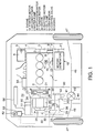
- a vehicle is provided with a parallel hybrid drive system comprising a gasoline engine 1 activated by a starter motor 1A and two motor/generators 10 and 26.
- the vehicle is also provided with a continuously variable transmission 30.
- a crank pulley 3 is connected to an end of a crank shaft 2 of the engine 1.
- the crank pulley 3 drives the pulley 6 of the air conditioner 5 through a auxiliary belt 4.
- Furthermore the crank pulley 3 drives a pulley 9 of a water pump 8 and a pulley 11 of a three phase induction motor/generator 10 through another auxiliary belt 7.
- the motor/generator 10 is operated as a motor by electrical force supplied from the battery not shown when the engine 1 not running and drives the air conditioner 5.
- the motor/generator 10 functions as a generator when the engine is running so as to charge a battery 71 shown in Fig. 2 as well as to supply power current to accessories.
- crank shaft 2 of the engine 1 is connected to a drive member 23 of an electrically activated powder clutch 22 through a flywheel 21,
- the drive member 23 is a ring shaped member which supports the exciting coils.
- a driven member 24 of the powder clutch 22 is connected to a drive shaft 25.
- the drive shaft 25 is connected to a rotor 27 of the three phase induction motor/generator 26.
- the three phase induction motor /generator 26 is provided with a stator 28 having a plurality of magnetic poles fixed facing the rotor 27.
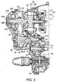
- the rotations of the drive shaft 25 are input into the V-belt continuously variable transmission 30.
- the continuously variable transmission 30 is provided with a primary pulley 31 and a secondary pulley 32 connected thereto via a V-belt 32.
- the primary pulley 31 comprises a fixed wheel 34 fixed to the drive shaft 25 and a movable wheel 36 arranged to move in an axial direction.
- the V-shaped pulley groove for accommodating the V-belt 32 is formed between these wheels 34, 36.
- the width of the pulley groove varies due to the axial displacement of the movable wheel 36 in response to the oil pressure supplied to oil chambers 35A and 35B.
- the oil pressure in the oil chambers 35A and 35B is supplied from a control valve 53 shown in Fig. 2 through an oil hole 56 formed on the inner section of the drive shaft 25 and the branching holes 56B and 56C which branch from the oil hole 56.
- the secondary pulley 33 is provided with a fixed wheel 38 integrated in the same way with the rotation shaft 37 and a movable wheel 39.
- the V-belt 32 is fitted in the V-shaped pulley groove formed between the wheels 38, 39.
- the width of the pulley groove between the wheels 38, 39 varies depending on the axial displacement of the movable pulley 39 in response to the oil pressure supplied to the oil chamber 55.
- the oil pressure in the oil chamber 55 is supplied from the control valve 53 through a oil hole 57A formed in the rotation shaft 37 and the branching hole 57B which branches off from the oil hole 57A.
- the rotation shaft 37 is connected to a drive gear 40.
- the drive gear 40 meshes with an idler gear 42 which is supported free to rotate by an idler shaft 41.
- a pinion 43 which is fixed to the same idler shaft 41 meshes with a final gear 44.
- the final gear 44 drives the drive wheels 47 through a differential gear unit 45 and drive shafts 46.
- the motor/generator 26 and the continuously variable transmission 30 are arranged in the casing 60 with the group of gears from the drive gear 40 to the final gear 44.
- An oil pump 51 which is driven by a motor 50 is provided on the outer side of the casing 60.
- the oil pressure generated by the oil pump 51 is supplied to the oil chambers 35A and 35B of the primary pulley 31 and the oil chamber 55 of the secondary pulley 33 through the control valve 53.
- the control valve 53 is operated by a step motor 52.
- the oil pump 51 also supplies lubricating oil to the components in the casing 60 and deposits oil to the oil cooler 56 for cooling.
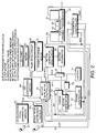
- the parallel hybrid drive system is controlled by the motor/generator controller 76, engine controller 70 and transmission controller 75, each of which comprises a microcomputer provided with a central processing unit (CPU), a read only memory (RAM), a random access memory (ROM) and an input/output interface (I/O interface).
- CPU central processing unit
- RAM read only memory
- ROM random access memory
- I/O interface input/output interface
- This vehicle is provided with an accelerator pedal 61 for transmitting an acceleration command from a driver to the engine 1.
- the accelerator pedal 61 is provided with an accelerator pedal depression sensor 62.
- the accelerator pedal depression sensor 62 detects a degree of depression of the accelerator pedal 61 and inputs a corresponding signal expressing the degree of accelerator pedal depression AS into the aforementioned three controllers 70, 75, 76.
- the vehicle is also provided with a brake pedal 63 and a brake pedal depression sensor 64 which detects a degree of depression of the brake pedal 63.
- the degree of brake depression BS detected by the brake operation sensor 64 is input into the generator/motor controller 76.
- An engine rotation speed sensor 65 is provided in the engine 1 which detects an engine rotation speed Ne and inputs corresponding signals into the aforementioned three controllers 70, 75, 76.
- An output rotation speed sensor 67 which detects a rotation speed Nsec of the secondary pulley 33 and an input rotation speed sensor 66 which detects a rotation speed Npri of the primary pulley 31 are fitted in the continuously variable transmission 30.
- the input and output rotation speeds detected by these rotation speed sensors 66 and 67 are input into the transmission controller 75.
- the engine 1, as shown in Fig. 1, is provided with an electric throttle 1D for regulating the air intake flowrate in an intake passage 1B.
- the electric throttle 1D is driven by a step motor 1C and the engine controller 70 controls the throttle opening of the electric throttle 1D by outputting a command signal to the step motor 1C.
- the output torque of the engine 1 varies depending on the output signal of the engine controller 70.
- the motor/generator 10 is connected to the battery 71 through a motor/generator drive circuit 72.
- the motor/generator drive circuit 72 is provided with an inverter and a chopper.
- the motor/generator controller 76 operates the motor/generator either as a motor or as a generator through an output signal to the motor/generator drive circuit 72.
- the battery has a voltage of 12V.
- the motor/generator 10 When the engine 1 is driven, the motor/generator 10 always functions as a generator.
- a signal is input from an air conditioner switch 68 showing the operational state of the air conditioner 5 into the motor/generator controller 76.
- the motor/generator 26 is connected to a power storage device 73 through a motor/generator drive circuit 74.
- the motor/generator drive circuit 74 is provided with a chopper and an inverter.
- the motor/generator controller 76 operates the motor/generator 26 either as a motor or as a generator through an output signal to the motor/generator drive circuit 74.
- the power storage device 73 is provided with a 345V chargeable battery and a condenser.
- the motor 50 is connected to a battery 73 through a pump drive circuit 80 which has a chopper and an inverter.
- the motor/generator controller 76 varies the rotation speed of the motor 50 through an output signal to the pump drive circuit 80 and thus varies the discharge of the oil pump 51.
- the motor/generator controller 76 also controls the release and engagement of the electrical powder clutch 22.
- the transmission controller 75 controls the drive ratio of the continuously variable transmission 30 through an output signal to the step motor 52.
- the transmission controller 75 calculates a vehicle speed VSP from an output rotation speed Nsec detected by the output rotation speed sensor 67. The transmission controller 75 then sets a target drive ratio im based on the input rotation speed Npri detected by the input rotation speed sensor 66 and the degree of depression of the accelerator pedal AS detected by the accelerator pedal depression sensor 62 and vehicle speed VSP .
- the target drive ratio im increases as the vehicle speed VSP decreases, it increases as the degree of accelerator pedal depression AS increases and it increases as the engine rotation speed Ne increases.
- a real drive ratio ip is calculated based on the input rotation speed Npri and the output rotation speed Nsec. Feed-back control is performed on the step motor 52 so that the real drive ration ip corresponds with the target drive ratio im.
- the control valve 53 which is driven by the step motor 52 varies an oil pressure which is transmitted to the oil chambers 35A, 35B, 55 of the continuously variable transmission 30 and varies the contact radius of the V-belt of the pulleys 31 and 33. In this way, the drive ratio of the continuously variable transmission 30 is varied.
- the drive ratio is defined as Npri Nsec.
- Signals showing the target drive ratio im and real drive ratio ip are input into the motor/generator controller 76 from the transmission controller 75. Furthermore signals indicative of the throttle a throttle opening TVO which is set by the engine controller 70, the engine rotation speed Ne, vehicle speed VSP, brake depression degree BS and accelerator pedal depression degree AS are input to the motor/generator controller 76.
- a signal which shows the operational state of the air conditioner 5 is input into the motor/generator controller 76.
- the motor/generator controller 76 controls the running of the vehicle based on these signals. Specifically, signals are output to the motor/generator drive circuits 72 and 74 and the electrical powder clutch 22. Also the command signals for the activation and termination of the engine 1 are output to the engine controller 70.
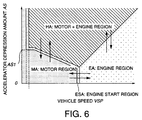
- the motor/generator controller 76 determines into which of the following four running regions of the vehicle falls in order to control running of the vehicle.
- a motor running region MA is a region in which the vehicle runs only on the output of the motor/generator 26.
- An engine running region EA is a region in which the vehicle runs only on the output of the engine 1.
- a hybrid running region HA is a region in which the vehicle performs normal running on the output of the engine 1 and uses the motor/generator 26 during acceleration.
- An engine activation region ESA is a region which is located on the border of the motor running region MA and the EA and HA regions on its periphery.
- These regions are pre-set depending on the vehicle speed VSP and degree of accelerator pedal depression AS as shown in Fig. 6 and are stored in map form in the motor/generator controller 76.
- the motor/generator controller 76 also controls the electrical powder clutch 22, the motor/generator 26 and the engine 1 depending on the pre-determined running regions.
- the motor/generator controller 76 also controls the oil pump drive circuit 80 and discharges from the oil pump 51 through the motor 50.
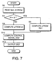
- the discharge control process of the oil pump 51 will now be described with reference to a flowchart in Fig. 7.
- the process is performed with a timer interrupt of, for example, 10 milliseconds.
- the motor/generator controller 76 reads the rotation speed Npri of the primary pulley 31, the target drive ratio im and the real drive ratio ip .
- a step S4 it is decided whether or not the real drive ratio ip corresponds with the target drive ratio im .
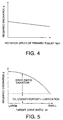
- a required discharge q of the oil pump 51 is calculated referring to the map shown in Fig. 4 based on the rotation speed Npri of the primary pulley 31. Based on the rotation speed Npri of the primary pulley, the map in Fig. 4 calculates the sum total of the minimum required discharge of oil to maintain the present drive ratio of the continuously variable transmission 30 in a steady state, the amount of oil supplied to the oil cooler 56 and the amount of lubricating oil supplied to the components in the casing 60. The map is pre-stored in the motor/generator controller 76. After the completion of the step S6, the routine proceeds to a step S10.
- step 4 when the real drive ratio ip does not correspond with the target drive ratio im , it means that drive ratio is varying in the transmission.
- the routine proceeds to a step S8.
- a required discharge q of the oil pump 51 is calculated.
- the map in Fig. 5 calculates the sum total of the required discharge of oil for the variation in the drive ratio of the continuously variable transmission 30, the amount of oil supplied to the oil cooler 56 and the amount of lubricating oil supplied to the components in the casing 60.
- the map is pre-stored in the motor/generator controller 76. After the completion of this calculation, the routine proceeds to a step S10.
- step S10 the control signal DC2 of the motor 50 in order to realize a required discharge q is calculated.
- control signal DC2 is output to the oil pressure pump drive circuit 80 and the routine is terminated.
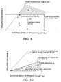
- the broken line in the figure shows the discharge of an example of a conventional oil pump directly connected to the input shaft of the continuously variable transmission.
- the conventional oil pump when the rotation speed Npri of the primary pulley 31 is low, the discharge is low.
- the rotation speed Npri when the rotation speed Npri is high, the real discharge greatly exceeds the required discharge which leads to the excess discharge shown in the region qy in the figure. This simply results in the drive force of the oil pump being used unnecessarily and in increase of the fuel consumption of the engine.
- this invention uses the motor 50 to drive the oil pump 51, it is possible to set the discharge independently of the rotation speed Npri of the primary pulley 31. Thus excess discharge is shown in region qy of the figure is removed from the discharge of the pump 51 which results in decreased fuel consumption.
- a coupled oil pressure pump 82 which rotates together with the drive shaft 25 is further provided between the motor/generator 26 and the V-belt continuously variable transmission 30.
- the coupled oil pressure pump 82 is not a large capacity pump as in the prior art. It is a small capacity pump which slowly increases the discharges depending on increases in the rotation speed Npri of the primary pump 31.
- the discharge of the coupled oil pressure pump 82 is set to value which is the sum of the lubrlcation oil amount supplied to the components in the casing 60, the minimum required discharge to maintain the drive ratio of the V-belt continuously variable transmission 30 and the oil amount supplied to the oil cooler 56.
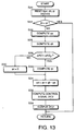
- the motor/generator controller 76 controls the discharge of the oil pump 51 according to the flowchart shown in Fig. 13.
- a step S20 the rotation speed Npri of the primary pump 31, the target drive ratio im , the real drive ratio ip and the degree of accelerator pedal depression AS are read.
- a step S22 it is decided whether or not the real drive ratio ip corresponds to the target drive ratio im in the same manner as S4 in the first embodiment.
- the routine proceeds to a step S24 and the subsequent steps so as to increase the discharge of the oil pump 51
- the excess discharge qa of the coupled oil pressure pump 82 is determined with reference to the map shown in Fig. 10 which is prestored in the motor/generator controller 76. This corresponds to the value of subtracting the amount of oil supplied to the oil cooler 56 and the lubrication oil amount of the components in the casing 60 from the discharge of the coupled oil pump 82.
- step S26 the required discharge qb for the drive ratio varying operation of the continuously variable transmission 30 is determined on the basis of the target drive ratio im with reference to the map shown in Fig. 11 which is prestored in the motor/generator controller 76. This corresponds to the map in Fig. 5 of the first embodiment of the invention.
- an accelerator pedal depression speed ⁇ AS is calculated from the difference of the degree of accelerator pedal depression AS at present and that detected in the immediately preceding occasion when the routine was performed, AS -1 .
- the accelerator pedal operation speed ⁇ AS is compared with reference value ⁇ AS 0 .
- ⁇ AS ⁇ ⁇ AS 0 it is decided that urgent operation of the continuously variable transmission 30 is not required.
- the routine proceeds to a step S30, an increment qc is set to 0, and the routine proceeds to a step S34.
- the routine proceeds to a step S32.
- step S32 the increment qc is calculated based on the accelerator pedal depression speed ⁇ AS by reference to the map shown in Fig. 12 which is prestored in the motor/generator controller 76, and the routine proceeds to a step S34.
- a discharge of the oil pump qd is calculated by subtracting the excess discharge qa from the sum of the increment qc and the required discharge qb for the drive ratio varying operation.
- step S35 the control signal DC2 of the motor 50 which corresponds to the discharge qd is calculated.
- step S36 the control signal DC2 is output to the oil pump drive circuit 80 and the routine terminates.
- the minimum oil discharge required for maintaining the present drive ratio of the continuously variable transmission 30, the oil amount supplied to the oil cooler 56 and the lubricating oil amount which is supplied to the components in the casing 60 are provided are provided from the coupled oil pump 82.
- the oil pump 51 is driven, the deviation between the discharge of the coupled oil pump 82 and the sum total of the required oil discharge to vary the drive ratio of the continuously variable transmission 30, the oil amount supplied to the oil cooler 56 and the lubricating oil amount which is supplied to the components in the casing 60 is supplied from the oil pressure pump 51.
- the coupled oil pump 82 consumes very little engine torque and has no adverse effect on engine fuel consumption since it is a small capacity pump which slowly increases discharges depending on the input rotation number N.
- this embodiment adds an oil temperature sensor in addition to the components in the aforesaid second embodiment.
- the oil temperature sensor 84 is a sensor which detects the temperature of an oil reservoir, not shown in the figure, which temporarily stores oil to be used as lubricant or for varying or maintaining the drive ratio.
- the detected oil temperature TS is input to the motor/generator controller 76.
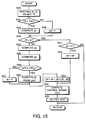
- the motor/generator controller 76 controls the discharge of the oil pump 51 by performing the routine shown in the flowchart in Fig. 15.
- step S40 the rotation speed Npri of the primary pulley 31, the target drive ratio im , the real drive ratio ip and the degree of accelerator pedal depression AS and the oil temperature TS are read.
- a present oil temperature TS and a reference value TS 0 which determines the required degree of cooling are compared.
- step S44 oil increment qe is calculated based on the oil temperature TS with reference to the map shown in Fig. 16 which is prestored in the motor/generator controller 76, and the routine proceeds to a step S48.
- step S46 oil increment qe is set to 0 and the routine proceeds to the step S48.
- step S48 it is determined whether a target drive ratio im corresponds to the real drive ratio ip in the same way as in the step S22 in the aforesaid second embodiment.
- step S50 it is determined whether or not the oil increment qe takes a positive value. If the oil increment qe takes a positive value, in a step S54, the oil increment qe is set to the discharge qd of the oil pump 51 and the routine proceeds to a step S66. If the oil increment qe does not take a positive value, no further processing is performed and the routine is terminated.
- Step S42 if the target drive ratio im does not corresponds to the real drive ratio ip , it is determined that the continuously variable transmission 30 is varying the drive ratio and the routine proceeds to a step S52.
- Steps S52 to S62 are the same as the steps S22 to S32 in the aforesaid second embodiment and will not be explained again here.
- a step S64 the discharge qd of the oil pump 51 is calculated by subtracting excess discharge qa from the sum total of the oil increments qc , qe and required discharge qb for the drive ratio varying operation
- a motor control signal DC2 corresponding to the discharge qd is calculated.
- step S68 the control signal DC2 is output to the oil pressure pump drive circuit 80 and the routine is terminated.
- This type of oil increment qe based on oil temperature TS can also be applied to the device corresponding to the aforesaid first embodiment.
- the generator/motor 26 may be connected to an output shaft of the continuously variable transmission 30 instead of being connected to the input shaft of the continuously variable transmission 30. Furthermore the generator/motor 26 need not be directly connected to the input or output shaft, but can be connected thereto through a rotation transmission member such as a belt or a set of gears.
Landscapes
- Engineering & Computer Science (AREA)
- Mechanical Engineering (AREA)
- Chemical & Material Sciences (AREA)
- Combustion & Propulsion (AREA)
- Transportation (AREA)
- General Engineering & Computer Science (AREA)
- Automation & Control Theory (AREA)
- Control Of Transmission Device (AREA)
- Hybrid Electric Vehicles (AREA)
- Electric Propulsion And Braking For Vehicles (AREA)
- Control Of Driving Devices And Active Controlling Of Vehicle (AREA)
- Control Of Vehicle Engines Or Engines For Specific Uses (AREA)
Applications Claiming Priority (2)
| Application Number | Priority Date | Filing Date | Title |
|---|---|---|---|
| JP35861097 | 1997-12-25 | ||
| JP35861097A JPH11189073A (ja) | 1997-12-25 | 1997-12-25 | ハイブリット車両の流体圧制御装置 |
Publications (2)
| Publication Number | Publication Date |
|---|---|
| EP0926401A2 true EP0926401A2 (fr) | 1999-06-30 |
| EP0926401A3 EP0926401A3 (fr) | 1999-12-22 |
Family
ID=18460212
Family Applications (1)
| Application Number | Title | Priority Date | Filing Date |
|---|---|---|---|
| EP98124592A Withdrawn EP0926401A3 (fr) | 1997-12-25 | 1998-12-23 | Dispositif d'alimentention de pression hydraulique pour transmission véhiculaire |
Country Status (3)
| Country | Link |
|---|---|
| US (1) | US6253137B1 (fr) |
| EP (1) | EP0926401A3 (fr) |
| JP (1) | JPH11189073A (fr) |
Cited By (8)
| Publication number | Priority date | Publication date | Assignee | Title |
|---|---|---|---|---|
| EP1103404A1 (fr) * | 1999-11-25 | 2001-05-30 | Honda Giken Kogyo Kabushiki Kaisha | Dispositif de lubrification pour vehicule hybride |
| NL1019457C2 (nl) * | 2001-11-30 | 2003-06-03 | Skf Ab | Continu variabel transmissiesysteem in een zelfdragend huis. |
| EP1069347A3 (fr) * | 1999-07-14 | 2003-09-24 | Honda Giken Kogyo Kabushiki Kaisha | Système de commande d'arrêt du fonctionnement d'un boíte de vitesses pour véhicules |
| NL1020498C2 (nl) * | 2002-04-26 | 2003-10-28 | Skf Ab | Continu variabel transmissiesysteem alsmede werkwijze voor het bedrijven van dat systeem. |
| EP1216871A3 (fr) * | 2000-12-22 | 2004-06-30 | Mazda Motor Corporation | Entraínement d'une pompe à huile dans un véhicule hybride |
| EP2078884A3 (fr) * | 2008-01-09 | 2010-08-04 | ZF Friedrichshafen AG | Boîte de vitesse automatique d'un véhicule automobile |
| US8187148B2 (en) | 2006-07-29 | 2012-05-29 | Zf Friedrichshafen Ag | Clutch system |
| CN104724108A (zh) * | 2013-12-18 | 2015-06-24 | 现代自动车株式会社 | 控制用于自动变速器的电油泵的装置和方法 |
Families Citing this family (34)
| Publication number | Priority date | Publication date | Assignee | Title |
|---|---|---|---|---|
| JP3550067B2 (ja) * | 2000-01-17 | 2004-08-04 | 本田技研工業株式会社 | ハイブリッド車両の制御装置 |
| JP3550068B2 (ja) * | 2000-01-24 | 2004-08-04 | 本田技研工業株式会社 | ハイブリッド車両の制御装置 |
| JP3775562B2 (ja) * | 2000-03-07 | 2006-05-17 | ジヤトコ株式会社 | パラレルハイブリッド車両 |
| JP3708784B2 (ja) * | 2000-03-22 | 2005-10-19 | ジヤトコ株式会社 | ハイブリッド車両の変速機ユニット |
| JP3512724B2 (ja) * | 2000-09-05 | 2004-03-31 | 本田技研工業株式会社 | 車両用自動変速機の油圧制御装置 |
| JP4576713B2 (ja) * | 2000-12-28 | 2010-11-10 | アイシン・エィ・ダブリュ株式会社 | オイルポンプの駆動制御装置 |
| JP3912235B2 (ja) | 2002-09-10 | 2007-05-09 | トヨタ自動車株式会社 | 車両の油圧制御装置 |
| JP3938897B2 (ja) * | 2002-09-30 | 2007-06-27 | ジヤトコ株式会社 | ベルト式無段変速機の油圧制御装置 |
| JP3783714B2 (ja) * | 2004-01-22 | 2006-06-07 | トヨタ自動車株式会社 | ハイブリッド車の制御装置 |
| US7494439B2 (en) * | 2004-08-26 | 2009-02-24 | Gm Global Technology Operations, Inc. | Dual drive pump with dual chain and roller clutch and method |
| JP2006233867A (ja) * | 2005-02-24 | 2006-09-07 | Aisin Seiki Co Ltd | 電動ポンプ及び流体供給装置 |
| JP2005344938A (ja) * | 2005-09-05 | 2005-12-15 | Aisin Aw Co Ltd | 補助油圧ユニット付き自動変速機 |
| JP4530999B2 (ja) * | 2006-02-23 | 2010-08-25 | 本田技研工業株式会社 | ハイブリッド車両の制御装置 |
| JP2007224887A (ja) * | 2006-02-27 | 2007-09-06 | Toyota Motor Corp | 油圧システム |
| JP4894475B2 (ja) * | 2006-11-21 | 2012-03-14 | トヨタ自動車株式会社 | エンジン始動装置 |
| KR101642448B1 (ko) * | 2008-02-08 | 2016-07-25 | 플래쉬루브 피티와이 엘티디 | 내연 기관용 윤활유 전달 시스템 |
| US8292012B2 (en) * | 2008-06-30 | 2012-10-23 | GM Global Technology Operations LLC | Apparatus and method for a quick start engine and hybrid system |
| JP5041249B2 (ja) | 2008-12-16 | 2012-10-03 | アイシン・エィ・ダブリュ株式会社 | 車両用駆動装置 |
| JP4873058B2 (ja) * | 2009-09-28 | 2012-02-08 | マツダ株式会社 | 車両用自動変速機 |
| US8636620B2 (en) | 2010-10-28 | 2014-01-28 | Jatco Ltd | Automatic transmission |
| JP5496855B2 (ja) | 2010-11-01 | 2014-05-21 | ジヤトコ株式会社 | 車両の制御装置 |
| JP5496854B2 (ja) | 2010-11-01 | 2014-05-21 | ジヤトコ株式会社 | 車両の制御装置 |
| JP5693152B2 (ja) | 2010-11-01 | 2015-04-01 | ジヤトコ株式会社 | 車両の油圧制御装置 |
| JP5383626B2 (ja) | 2010-11-01 | 2014-01-08 | ジヤトコ株式会社 | 車両の制御装置 |
| JP5693151B2 (ja) | 2010-11-01 | 2015-04-01 | ジヤトコ株式会社 | 車両の制御装置 |
| JP5501937B2 (ja) * | 2010-11-02 | 2014-05-28 | ジヤトコ株式会社 | ハイブリッド車両の制御装置 |
| KR101241210B1 (ko) | 2010-12-07 | 2013-03-13 | 기아자동차주식회사 | 하이브리드 자동차의 오일펌프 제어장치 및 방법 |
| JP5501260B2 (ja) | 2011-02-03 | 2014-05-21 | ジヤトコ株式会社 | 車両の制御装置 |
| KR101326850B1 (ko) * | 2012-10-04 | 2013-11-11 | 기아자동차주식회사 | 오일펌프 제어 시스템 및 방법 |
| JP6163831B2 (ja) * | 2013-03-29 | 2017-07-19 | マツダ株式会社 | エンジンのオイル供給装置 |
| US9168913B2 (en) * | 2013-07-11 | 2015-10-27 | Hyundai Motor Company | Oil pump system of hybrid vehicle and method for controlling the same |
| JP6418044B2 (ja) | 2015-04-08 | 2018-11-07 | トヨタ自動車株式会社 | 車両の制御装置 |
| JP6560720B2 (ja) * | 2017-08-10 | 2019-08-14 | 本田技研工業株式会社 | 油圧制御装置 |
| JP6849078B2 (ja) * | 2017-08-28 | 2021-03-24 | アイシン・エィ・ダブリュ株式会社 | 制御装置 |
Citations (1)
| Publication number | Priority date | Publication date | Assignee | Title |
|---|---|---|---|---|
| EP0788914A2 (fr) | 1995-08-31 | 1997-08-13 | Toyota Jidosha Kabushiki Kaisha | Commande de véhicule |
Family Cites Families (14)
| Publication number | Priority date | Publication date | Assignee | Title |
|---|---|---|---|---|
| JPS5314697B2 (fr) * | 1972-09-08 | 1978-05-19 | ||
| JPS5797942A (en) * | 1980-12-11 | 1982-06-17 | Honda Motor Co Ltd | Change gear operated by oil pressure for car |
| JP2893757B2 (ja) * | 1989-10-18 | 1999-05-24 | 日産自動車株式会社 | 変速機の油圧制御装置 |
| DE4134268C2 (de) * | 1990-10-29 | 2001-05-17 | Volkswagen Ag | Antriebsanordnung für ein Kraftfahrzeug |
| JP3134368B2 (ja) | 1991-06-28 | 2001-02-13 | ソニー株式会社 | 圧縮データ記録再生装置 |
| DE4223846C2 (de) * | 1992-07-20 | 1996-03-28 | Hydromatik Gmbh | Getriebeeinheit zur Anordnung zwischen einem Antriebsmotor und einem Verbraucher |
| JP3343660B2 (ja) * | 1992-12-10 | 2002-11-11 | 本田技研工業株式会社 | オイルポンプ駆動装置 |
| NL1001279C2 (nl) * | 1995-09-25 | 1997-03-26 | Doornes Transmissie Bv | Continu variabele transmissie. |
| JP3536533B2 (ja) * | 1996-06-11 | 2004-06-14 | トヨタ自動車株式会社 | 車両用自動変速機の変速制御装置 |
| KR100191579B1 (ko) * | 1996-11-19 | 1999-06-15 | 정몽규 | 자동변속기용 유압제어 시스템 및 그 제어방법 |
| JP3261523B2 (ja) * | 1997-01-10 | 2002-03-04 | 株式会社ユニシアジェックス | 車両の制御装置 |
| JP3211697B2 (ja) * | 1997-02-10 | 2001-09-25 | 日産自動車株式会社 | 無段変速機の目標変速比生成装置 |
| JP3211714B2 (ja) * | 1997-04-08 | 2001-09-25 | 日産自動車株式会社 | 無段変速機の変速比制御装置 |
| DE19757603B4 (de) * | 1997-12-23 | 2004-03-18 | Hyundai Motor Company | Druckeinstellventil und mit demselben ausgestattetes Hydrauliksteuersystem eines Automatikgetriebes |
-
1997
- 1997-12-25 JP JP35861097A patent/JPH11189073A/ja active Pending
-
1998
- 1998-12-23 EP EP98124592A patent/EP0926401A3/fr not_active Withdrawn
- 1998-12-24 US US09/220,341 patent/US6253137B1/en not_active Expired - Fee Related
Patent Citations (1)
| Publication number | Priority date | Publication date | Assignee | Title |
|---|---|---|---|---|
| EP0788914A2 (fr) | 1995-08-31 | 1997-08-13 | Toyota Jidosha Kabushiki Kaisha | Commande de véhicule |
Cited By (11)
| Publication number | Priority date | Publication date | Assignee | Title |
|---|---|---|---|---|
| EP1069347A3 (fr) * | 1999-07-14 | 2003-09-24 | Honda Giken Kogyo Kabushiki Kaisha | Système de commande d'arrêt du fonctionnement d'un boíte de vitesses pour véhicules |
| EP1103404A1 (fr) * | 1999-11-25 | 2001-05-30 | Honda Giken Kogyo Kabushiki Kaisha | Dispositif de lubrification pour vehicule hybride |
| US6527074B1 (en) | 1999-11-25 | 2003-03-04 | Honda Giken Kogyo Kabushiki Kaisha | Lubricating structure for a hybrid vehicle |
| EP1216871A3 (fr) * | 2000-12-22 | 2004-06-30 | Mazda Motor Corporation | Entraínement d'une pompe à huile dans un véhicule hybride |
| NL1019457C2 (nl) * | 2001-11-30 | 2003-06-03 | Skf Ab | Continu variabel transmissiesysteem in een zelfdragend huis. |
| WO2003046414A1 (fr) * | 2001-11-30 | 2003-06-05 | Ab Skf | Systeme de transmission a variation continue loge dans un boitier independant |
| NL1020498C2 (nl) * | 2002-04-26 | 2003-10-28 | Skf Ab | Continu variabel transmissiesysteem alsmede werkwijze voor het bedrijven van dat systeem. |
| US8187148B2 (en) | 2006-07-29 | 2012-05-29 | Zf Friedrichshafen Ag | Clutch system |
| EP2078884A3 (fr) * | 2008-01-09 | 2010-08-04 | ZF Friedrichshafen AG | Boîte de vitesse automatique d'un véhicule automobile |
| CN104724108A (zh) * | 2013-12-18 | 2015-06-24 | 现代自动车株式会社 | 控制用于自动变速器的电油泵的装置和方法 |
| CN104724108B (zh) * | 2013-12-18 | 2019-08-30 | 现代自动车株式会社 | 控制用于自动变速器的电油泵的装置和方法 |
Also Published As
| Publication number | Publication date |
|---|---|
| EP0926401A3 (fr) | 1999-12-22 |
| JPH11189073A (ja) | 1999-07-13 |
| US6253137B1 (en) | 2001-06-26 |
Similar Documents
| Publication | Publication Date | Title |
|---|---|---|
| US6253137B1 (en) | Oil pressure supply device for vehicle drive system | |
| US6009365A (en) | Vehicle drive system controller and control method | |
| US6064161A (en) | Vehicle drive device and vehicle drive device control method | |
| US6122587A (en) | Vehicle drive system controller and control method | |
| EP0943475B1 (fr) | Dispositif de régulation de force d'entraínement pour véhicules hybrides | |
| JP3211638B2 (ja) | 車両の制御装置 | |
| KR100554926B1 (ko) | 차량의 제어장치 | |
| US6007443A (en) | Hybrid vehicle | |
| JP3913735B2 (ja) | 車両のハイブリッドドライブの動作点の調整方法 | |
| US6053842A (en) | Drive system for hybrid drive vehicle | |
| US20010022166A1 (en) | Starting control apparatus for internal combustion engine | |
| JP3011069B2 (ja) | 車両の制御装置 | |
| JP3716659B2 (ja) | 車両の走行制御装置 | |
| JP3376999B2 (ja) | ハイブリッド車の駆動制御装置 | |
| JP4240845B2 (ja) | ハイブリッド車 | |
| US6366838B1 (en) | Vehicle control device | |
| EP0925979B1 (fr) | Transmission pour un véhicule automobile | |
| JP3648411B2 (ja) | 自動変速機用電動油圧ポンプ制御装置および方法 | |
| JP6428706B2 (ja) | 車両の制御装置 | |
| JP2001286003A (ja) | パラレルハイブリッド車両 | |
| JP4411795B2 (ja) | 駆動装置およびその制御方法 | |
| JP3876503B2 (ja) | ハイブリット駆動装置における発進制御装置 | |
| JP3778120B2 (ja) | ハイブリッド自動車 | |
| JP3695414B2 (ja) | 発電機の制御装置およびこれを備える動力出力装置 | |
| JP3882737B2 (ja) | ハイブリッド自動車およびその制御方法 |
Legal Events
| Date | Code | Title | Description |
|---|---|---|---|
| PUAI | Public reference made under article 153(3) epc to a published international application that has entered the european phase |
Free format text: ORIGINAL CODE: 0009012 |
|
| 17P | Request for examination filed |
Effective date: 19981223 |
|
| AK | Designated contracting states |
Kind code of ref document: A2 Designated state(s): DE GB |
|
| AX | Request for extension of the european patent |
Free format text: AL;LT;LV;MK;RO;SI |
|
| PUAL | Search report despatched |
Free format text: ORIGINAL CODE: 0009013 |
|
| AK | Designated contracting states |
Kind code of ref document: A3 Designated state(s): AT BE CH CY DE DK ES FI FR GB GR IE IT LI LU MC NL PT SE |
|
| AX | Request for extension of the european patent |
Free format text: AL;LT;LV;MK;RO;SI |
|
| AKX | Designation fees paid |
Free format text: DE GB |
|
| 17Q | First examination report despatched |
Effective date: 20020924 |
|
| STAA | Information on the status of an ep patent application or granted ep patent |
Free format text: STATUS: THE APPLICATION IS DEEMED TO BE WITHDRAWN |
|
| 18D | Application deemed to be withdrawn |
Effective date: 20030205 |