EP0921055A2 - Cabine de conducteur d'une machine de chantier - Google Patents
Cabine de conducteur d'une machine de chantier Download PDFInfo
- Publication number
- EP0921055A2 EP0921055A2 EP98204095A EP98204095A EP0921055A2 EP 0921055 A2 EP0921055 A2 EP 0921055A2 EP 98204095 A EP98204095 A EP 98204095A EP 98204095 A EP98204095 A EP 98204095A EP 0921055 A2 EP0921055 A2 EP 0921055A2
- Authority
- EP
- European Patent Office
- Prior art keywords
- operator
- cab
- reinforcement member
- construction machine
- hollow pillar
- Prior art date
- Legal status (The legal status is an assumption and is not a legal conclusion. Google has not performed a legal analysis and makes no representation as to the accuracy of the status listed.)
- Granted
Links
Images


Classifications
-
- E—FIXED CONSTRUCTIONS
- E02—HYDRAULIC ENGINEERING; FOUNDATIONS; SOIL SHIFTING
- E02F—DREDGING; SOIL-SHIFTING
- E02F9/00—Component parts of dredgers or soil-shifting machines, not restricted to one of the kinds covered by groups E02F3/00 - E02F7/00
- E02F9/16—Cabins, platforms, or the like, for drivers
- E02F9/163—Structures to protect drivers, e.g. cabins, doors for cabins; Falling object protection structure [FOPS]; Roll over protection structure [ROPS]
-
- B—PERFORMING OPERATIONS; TRANSPORTING
- B62—LAND VEHICLES FOR TRAVELLING OTHERWISE THAN ON RAILS
- B62D—MOTOR VEHICLES; TRAILERS
- B62D21/00—Understructures, i.e. chassis frame on which a vehicle body may be mounted
- B62D21/09—Means for mounting load bearing surfaces
-
- B—PERFORMING OPERATIONS; TRANSPORTING
- B62—LAND VEHICLES FOR TRAVELLING OTHERWISE THAN ON RAILS
- B62D—MOTOR VEHICLES; TRAILERS
- B62D27/00—Connections between superstructure or understructure sub-units
- B62D27/02—Connections between superstructure or understructure sub-units rigid
- B62D27/026—Connections by glue bonding
-
- B—PERFORMING OPERATIONS; TRANSPORTING
- B62—LAND VEHICLES FOR TRAVELLING OTHERWISE THAN ON RAILS
- B62D—MOTOR VEHICLES; TRAILERS
- B62D33/00—Superstructures for load-carrying vehicles
- B62D33/06—Drivers' cabs
Definitions
- the present invention relates to an operator's cab (room) in a construction machine such as a hydraulic shovel, a wheel loader or the like.
- the structures adopted for operator's cabs of hydraulic shovels in the prior art include one that is constituted by bonding an inner panel provided toward the operator's cab and an outer panel provided on the outside of the inner panel, and further distending a portion of the inner panel and a portion of the outer panel inward and outward respectively relative to the operator's cab to form hollow pillar portions.
- reinforcement member constituted of steel pipe or steel bar may be inserted inside the hollow pillar portions to improve the strength against a tipping load, as disclosed in, for instance, Japanese Laid-open Patent Publication No. Heisei-9-25648.
- the size of the steel pipe or the steel bar to be used is subject to restriction imposed by the shape of the pillar if the reinforcement member is to be inserted while maintaining the existing pillar shape, and thus, it is difficult to achieve an optimal shape for the pillar portion in terms of strength.
- the pillar shape is changed to accommodate the steel pipe or the steel bar, it will lead to a major design modification and an increase in the production cost.
- An object of the present invention is to provide an operator's cab in a construction machine whose strength can be improved effectively without having to greatly change the shape of pillars in an existing operator's cab.
- an operator's cab in a construction machine according to the present invention in which hollow pillar portions are formed each with an outer panel and an inner panel bonded to each other and the hollow pillar portions constitute an operator's cab frame, comprises: at least one reinforcement member constituted of thin plate that is bonded to the outer panel and/or the inner panel to divide an internal space of each of the hollow pillar portions.
- the strength of the pillar portions can be improved effectively while retaining the shape of an existing operator's cab to achieve an improvement in the strength of the operator's cab against a tipping load.
- the reinforcement members are constituted of thin plate, a higher degree of freedom is afforded in design compared to design that employs commercially available steel pipe or steel bar and an optimal shape for strength can be achieved.
- a modulus of section in each of the hollow pillar portions is gradually increased toward a bottom surface of the operator's cab frame to lessen bending stress at the hollow pillar portion.
- the reinforcement member is bonded to a base plate constituting a bottom portion of the operator's cab.
- the reinforcement member can be distanced from a base plate constituting a bottom portion of the operator's cab.
- the reinforcement member can be provided at only minimum places to be required and the material cost of the reinforcement member can be reduced.
- the hollow pillar portions are each constituted of elongated space and the reinforcement member is provided along a direction of length of the elongated space.
- the operator's cab achieves a so-called beam structure and the strength of the operator's cab is effectively improved.
- the hollow pillar portions are provided at, at least, one set of left and right ends among left and right ends at a front surface of the operator's cab, left and right ends at a rear surface of the operator's cab and left and right ends in a middle area located between the left and right ends at the front surface and the left and right ends at the rear surface of the operator's cab.
- a cross sectional shape of the reinforcement member has a roughly square bracket shape.
- the modulus of section of the reinforcement member can be increased effectively.
- Another operator's cab in a construction machine according to the present invention in which hollow pillar portions are formed each with an outer panel and an inner panel bonded to each other and the hollow pillar portions constitute an operator's cab frame, comprises: at least one reinforcement member constituted of thin plate that is bonded to an outer side of each hollow pillar portion to form a hollow portion outside the internal space of the hollow pillar portion.
- a cross sectional shape of the reinforcement member has a roughly square bracket shape, too.
- Another operator's cab in a construction machine according to the present invention in which hollow pillar portions are formed each with an outer panel and an inner panel bonded to each other and the hollow pillar portions constitute an operator's cab frame, comprises: mid hollow pillar portions that are provided at left and right ends in a middle area located between a front surface and a rear surface of the operator's cab; and a reinforcement member that is provided at each of the mid hollow pillar portions.
- the reinforcement member is constituted of thin plate and furthermore a cross sectional shape of the reinforcement member has a roughly square bracket shape, too.
- Another operator's cab in a construction machine according to the present invention in which hollow pillar portions are formed each with an outer panel and an inner panel bonded to each other and the hollow pillar portions and a roof which is provided above the hollow pillar portions constitute an operator's cab frame, comprises: a roof reinforcement member that extends left and right in the operator's cab and is bonded to the roof to form a hollow portion between the roof reinforcement member and the roof.
- This operator's cab in a construction machine preferably, further comprises a pillar reinforcement member at the hollow pillar portion. Furthermore, preferably, the pillar reinforcement member and the roof reinforcement member are bonded to form an integrated structure.
- the roof reinforcement member is constituted of thin plate and furthermore a cross sectional shape of the roof reinforcement member has a roughly square bracket shape, too.
- the hollow pillar portions are provided at, at least, one set of left and right ends among left and right ends at a front surface, left and right ends at a rear surface and left and right ends in a middle area located between the left and right ends at the front surface and the left and right ends at the rear surface of the operator's cab and the roof reinforcement member is mounted laterally between upper ends of a pair of the hollow pillar portions.
- this operator's cab in a construction machine comprises a pillar reinforcement member at the hollow pillar portion.
- the pillar reinforcement member and the roof reinforcement member are bonded to form an integrated structure.
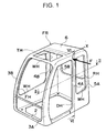
- FIG. 1 shows a perspective view illustrating the frame structure of the operator's cab of a hydraulic shovel.
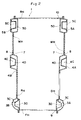
- FIG. 2 shows a cross section of the operator's cab in an embodiment of the present invention along the horizontal direction.
- FIG. 3 shows a cross section of a first pillar in the embodiment along the horizontal direction.
- FIG. 4 shows a cross section of a second pillar in the embodiment along the horizontal direction.
- FIG. 5 shows a cross section of a third pillar in the embodiment along the horizontal direction
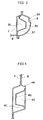
- FIG. 6 shows a cross section of the second pillar in the embodiment along the vertical direction.
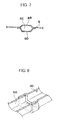
- FIG. 7 shows a cross section of a side of the roof portion above the second pillar in the embodiment.
- FIG. 8 shows a perspective view illustrating the bonding of a longitudinal reinforcement member and a lateral reinforcement member in the embodiment.
- FIG. 9 shows the relationship between the tipping load applied to a side surface of the operator's cab and displacement.
- FIG. 10 shows a cross section of a first pillar along the horizontal direction in an example of a variation of the embodiment.
- FIG. 11 shows a cross section of a first pillar along the horizontal direction in another example of a variation of the embodiment.
- FIG. 12 shows a cross section of a first pillar along the horizontal direction in yet another example of a variation of the embodiment.
- FIG. 13 shows a cross section of a first pillar along the horizontal direction in yet another example of a variation of the embodiment.
- FIG. 14 shows a cross section of a first pillar along the horizontal direction in yet another example of a variation of the embodiment.
- FIG. 15 shows a cross section of a second pillar along the vertical direction in an example of a variation of the embodiment.
- FIG. 16 shows a cross section the upper portion of the second pillar along the vertical direction in an example of a variation of the embodiment.
- FIG. 17 shows the frame structure in an example of a variation of the operator's cab in the embodiment
- FIG. 1 is a perspective view illustrating the frame structure of the operator's cab in an embodiment of the present invention and FIG. 2 is a cross section along line II-II in FIG. 1.
- the left side surface and the right side surface of the operator's cab 1 are each constituted of a pair of panels, i.e., an inner panel 7 and an outer panel 8, whereas the front surface and the rear surface of the operator's cab 1 are respectively constituted of a front panel 9 and a rear panel 10.
- the inner panel 7 and the outer panel 8 are bonded to overlap each other, and hollow (or empty) pillar portions are formed between the inner panel 7 and the outer panel 8 at the frontmost portion, the rearmost portion and the middle portion located between them, of the operator's cab 1.
- first pillars 3A and 3B These pillar portions are referred to as first pillars 3A and 3B, second pillars 4A and 4B and third pillars 5A and 5B from the front to the rear, and first reinforcement members 30, 40 and 50 that are to be detailed later are provided inside the individual pillars 3A and 3B through 5A and 5B.
- the bottom surface of the operator's cab 1 is formed with a base plate 2, and the first pillars 3A and 3B through third pillars 5A and 5B are provided standing erect on the base plate 2.
- the top surface of the operator's cab 1 is constituted of a roof 6 provided at the upper ends of the pillars 3A and 3B through 5A and 5B.
- the operator's cab frame FR constituting the main frame structure of the operator's cab 1 is constituted of the individual surfaces at the front, at the rear, at the left, at the right, at the top and at the bottom to achieve a roughly rectangular parallelopiped.
- an opening FH for mounting a front glass and an opening RH for mounting a rear glass are provided respectively, with an opening WH for mounting a window provided at both the left side surface and the right side surface of the frame FR.
- An opening DH for mounting a door is provided at the left side surface of the frame FR, and an opening TH for mounting a skylight is provided at the front side of the roof 6.
- the shapes of the pillars in this embodiment are explained in reference to FIGS. 3 through 5 that are enlargements of the first pillar 3A, the second pillar 4A and the third pillar 5A in FIG. 2.
- the first pillar portion 3A is provided with a hollow portion 3C between the inner panel 7 and the outer panel 8 having cross sections achieving rough "]" shapes (Square bracket or Japanese letter “]” shape) facing opposite each other and distended inward and outward respectively, and the front and rear portions of the inner panel 7 and the outer panel 8 are bonded with each other one on top of the other.
- a longitudinal reinforcement plate 30 with its cross section achieving a rough "]" shape to face opposite the inner panel 7 is provided and the inner surface of the longitudinal reinforcement plate 30 in the back and forth direction of the operator's cab is bonded to the inner surface of the inner panel 7 at two locations that are distanced from each other to divide the hollow portion 3C into two portions.
- An end of the front panel 9, with its cross section achieving an L shape, is bonded to the inner surface of the inner panel 7 at the bonding area of the inner panel 7 and the outer panel 8 toward the front.
- the longitudinal reinforcement member 30 is formed by press-processing a thin plate.
- the second pillar portion 4A is provided with a hollow portion 4C between the inner panel 7 and the outer panel 8 having cross sections formed in rough "]" shapes facing opposite each other, as in the case with the first pillar portion 3A.
- a longitudinal reinforcement plate 40 with its cross section achieving a rough "]" shape to face opposite the outer panel 8 is provided and the outer surface of the longitudinal reinforcement plate 40 in the back and forth direction of the operator's cab is bonded to the inner surface of the outer panel 8 at two locations that are distanced from each other to divide the hollow portion 3C into two portions.
- the longitudinal reinforcement member 40 is formed by press-processing a thin plate.
- the third pillar portion 5A is provided with a hollow portion 5C between the inner panel 7 and the outer panel 8 having cross sections formed in rough "]" shapes facing opposite each other, as in the case with the first pillar portion 3A.
- a longitudinal reinforcement plate 50 with its cross section achieving a rough "]" shape to face opposite the outer panel 8 is provided and the outer surface of the longitudinal reinforcement plate 50 in the back and forth direction of the operator's cab is bonded to the inner surface of the outer panel 8 at two locations that are distanced from each other to divide the hollow portion 5C into two portions.
- the longitudinal reinforcement member 50 is formed by press-processing a thin plate. It is to be noted that the individual pairs of pillar portions 3A and 3B through 5A and 5B constituting part of the operator's cab frame FR achieve left / right symmetry, and the pillar portions 3B, 4B and 5B whose explanation is omitted here, too, are provided with longitudinal reinforcement plates 30, 40 and 50 respectively as are the pillar portions 3A, 4A and 5A explained above.
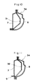
- FIG. 6 is a cross section along line VI-VI in FIG. 1 (a cross section of the second pillar 4A along the vertical direction) .
- the lower end of the outer panel 8 is bonded to the outer surface of the base plate 2 having a cross section achieving an L shape.
- the upper portion of the outer panel 8 is bent toward the inside of the operator's cab 1 almost at a right angle with the inner surface of a flange 8A provided at the upper end bonded to the outer surface of the upper end 7A of the inner panel 7.
- the longitudinal reinforcement member 40 mentioned earlier is provided parallel to the outer panel 8, and the lower end of the longitudinal reinforcement member 40 is bonded to the upper surface of the base plate 2.
- the upper portion of the longitudinal reinforcement member 40 is bent toward the inside of the operator's cab 1 almost at a right angle, with its front end passing through an opening portion 7B of the inner panel 7 opening in a shape that is the same as the cross section of the longitudinal reinforcement plate 40 to be bonded to the inner panel 7 at the opening portion 7B.
- the lower end of the inner panel 7 is bonded to the upper surface of the base plate 2, and a rail bend 7C for housing the front glass is provided in the upper portion of the inner panel. Exactly the same structure is assumed for the second pillar 4B.
- FIG. 7 which is a cross section along line VII-VII in FIG. 6, in the areas of the roof 6 where the upper ends of the second pillars 4A and 4B are bonded, a distended portion 6B extends to the left and right in the operator's cab.
- a lateral reinforcement member 60 having a cross section achieving a rough "]" shape to face opposite the distended portion 6B, which extends to the left and right in the operator's cab, is bonded to the roof 6 at two locations distanced from each other in the back and forth direction of the operator's cab to form a hollow portion 6C.
- a flange 6A is provided at the left end of the roof 6 (at the right end in FIG. 6), with a side surface of the flange 6A bonded to the inner surface of the upper end 7A of the inner panel.
- FIG. 8 which is a perspective view of the VIII area in FIG. 6, the left end of the lateral reinforcement member 60 (the right end portion in FIG. 6) is press-processed to achieve a staged shape (so-called joggled processing) so that the right end of the longitudinal reinforcement member 40 (the left end portion in FIG. 6) is fitted in and bonded at the staged portion.
- hollow portions 6C constituted by distended portions 6B and lateral reinforcement members 60 are provided in the areas of the roof 6 between the first pillars 3A and 3B and between the third pillars 5A and 5B that are not shown, as in the area between the second pillars 4A and 4B. Since the reinforcement member is provided at the roof, the rigidity in the upper portion of the operator's cab improves, which, in turn, improves the strength against an object falling from above. Also, since the pillar portions, the distended portion and the lateral reinforcement member of the roof constitute elongated space, the operator's cab achieves a so-called beam structure, accordingly the strength of the operator's cab effectively improved.
- a tipping load F is applied to an X portion of the operator's cab 1 at the left side (the second pillar 4A) in FIG. 1 and the relationship between the deformation quantity at the X portion and the tipping load is illustrated in FIG. 9.
- the curve A represents the strength characteristics of an operator's cab in the prior art that is not provided with reinforcement members and the curve B represents the strength characteristics of the operator's cab in the embodiment provided with the reinforcement members 30, 40, 50 and 60.
- the strength of the operator's cab in the embodiment demonstrates a great improvement over that in the prior art.
- the longitudinal reinforcement members 30, 40 and 50 and the lateral reinforcement members 60 constituted of thin plate are provided at the pillars 3A and 3B through 5A and 5B and the roof 6 of the operator's cab frame FR in the embodiment, the strength of the operator's cab 1 can be improved effectively without degrading of freedom in design that would otherwise result if commercially available steel pipe or steel bar were employed to constitute the reinforcement members.
- the inner panel 7 and the outer panel 8 in the prior art can be utilized as is, no significant modification is required in the manufacturing process and the increase in the production cost is minimized.
- the reinforcement members 30, 40, 50 and 60 are provided only at the pillars 3A and 38 through 5A and 5B and the roof 6 constituting the main frame of the operator's cab 1, the increase in weight due to the use of the reinforcement members can be minimized to ensure that the operating performance and the like are not adversely affected.
- the shape of the longitudinal reinforcement member 30 provided at the first pillar 3A is illustrated in FIG. 3, the shape of the reinforcement member 30 may be as illustrated in FIGS. 10 through 14, instead, and these alternatives are explained below.
- a longitudinal reinforcement member 31 with a cross section achieving a roughly "]" shape is sandwiched and clamped at the bonding areas of the inner panel 7 distended inward and the outer panel 8 distended outward in the back and forth direction of the operator's cab at two locations distanced from each other.
- a longitudinal reinforcement member 32 is sandwiched and clamped at a bonding area of the inner panel 7 and the outer panel 8, as in FIG. 10.
- the shapes of the inner panel 7 and the outer panel 8 at the front are different from those in FIG. 10.
- a longitudinal reinforcement member 33 is sandwiched and clamped at a bonding area of the inner panel 7 and the outer panel 8, with its front end bonded to the inner surface of the distended inner panel 7. Providing such a longitudinal reinforcement member 33 will hide a bonding area of the longitudinal reinforcement member 33 within the pillar to achieve an esthetic improvement.
- a longitudinal reinforcement member 34 is bonded to the outer surface of the outer panel 8 to form another hollow portion 3D adjacent to and outside of the hollow portion 3C provided between the inner panel 7 and the outer panel 8.
- the front and rear ends of longitudinal reinforcement members 35 and 36 are bonded to the inner surface of the inner panel 7 and the inner surface of the outer panel 8 respectively within the hollow portion 3C provided between the inner panel 7 and the outer panel 8 to divide the hollow portion 3C into three portions.
- the shapes of the reinforcement members 30, 40, 50 and 60 are not restricted to those adopted in the embodiment, and any other shapes may be adopted for them as long as they contribute to an improvement in the modulus of section.
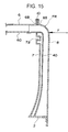
- the positioning arrangement is not limited to this and the lower portions of the inner panel 7 and the longitudinal reinforcement members 40 may curve toward the inside of the operator's cab, as illustrated in FIG. 15, for instance.
- the modulus of section near the bottom surface of the operator's cab (the low portion of the side surface of the operator's cab) is increased, any excessive bending stress near the bottom surface will be suppressed. This will further improve the flexural rigidity of the operator's cab frame FR against the tipping load F applied to the upper portion of the side surface of the operator's cab 1.
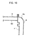
- the longitudinal reinforcement members 30, 40 and 50 and the lateral reinforcement member 60 are provided in the operator's cab 1 in the embodiment described above, only the longitudinal reinforcement members 30, 40 and 50 may be provided at the pillar portions 3A and 3B through 5A and 5B, or as illustrated in FIG. 16, which is a cross section of the upper portion of the second pillar 4A along the vertical direction, only the lateral reinforcement member 60 may be provided.
- FIG. 17 which presents a perspective view of another frame structure for the operator's cab
- a roof guard 11 supported by the reinforcement members 30, 40, 50 and 60 of the pillars 3A and 3B through 5A and 5B may be provided above the roof 6. This will further improve the rigidity of the roof 6 and also a sufficient degree of strength can be achieved for the operator's cab even against an object falling from above.
- the longitudinal reinforcement members 30, 40 and 50 and the lateral reinforcement member 60 are mounted continuously from the base plate 2 to the upper surface via the side surfaces of the operator's cab 1 between the left and right in the embodiment described above, they may be provided non-continuously to be present intermittently only at locations that need to be reinforced to ensure strength. Accordingly, the base plate 2 and the longitudinal reinforcement members 30, 40 and 50 may not be bonded to each other and may be distanced from each other.
- the inner panel 7, the outer panel 8, the reinforcement members 30, 40, 50 and 60 and the like may be bonded together through welding, brazing, adhesive, bolts, rivets or bonded through any other method.
- the longitudinal reinforcement members 30, 40 and 50 are provided in the pillars 3A and 3B through 5A and 5B, respectively.
- all pillars may not be provided with the longitudinal reinforcement members, and only one of pairs of the pillars 3A and 3B through 5A and 5B may be provided with the longitudinal reinforcement members, or two of pairs of the pillars 3A and 3B through 5A and 5B may be provided with the longitudinal reinforcement members.
- the strength of the front surface of the operator's cab may be maintained to the certain degree by the front panel 9 and the strength of the rear surface of the operator's cab may be maintained to the certain degree by the rear panel 10, only the mid pillars 4A and 4B that do not have such a panel around there can be provided with the longitudinal reinforcement members 40.
- the strength of the operator's cab is effectively improved with small amount of materials.
- safety is effectively improved with small amount of materials or members.
Landscapes
- Engineering & Computer Science (AREA)
- Chemical & Material Sciences (AREA)
- Combustion & Propulsion (AREA)
- Transportation (AREA)
- Mechanical Engineering (AREA)
- Mining & Mineral Resources (AREA)
- Civil Engineering (AREA)
- General Engineering & Computer Science (AREA)
- Structural Engineering (AREA)
- Body Structure For Vehicles (AREA)
- Component Parts Of Construction Machinery (AREA)
Priority Applications (1)
| Application Number | Priority Date | Filing Date | Title |
|---|---|---|---|
| EP03077700A EP1369341B1 (fr) | 1997-12-04 | 1998-12-03 | Cabine de conducteur d'une machine de chantier |
Applications Claiming Priority (2)
| Application Number | Priority Date | Filing Date | Title |
|---|---|---|---|
| JP33446397 | 1997-12-04 | ||
| JP33446397A JP3474417B2 (ja) | 1997-12-04 | 1997-12-04 | 建設機械の運転室 |
Related Child Applications (2)
| Application Number | Title | Priority Date | Filing Date |
|---|---|---|---|
| EP03077700A Division EP1369341B1 (fr) | 1997-12-04 | 1998-12-03 | Cabine de conducteur d'une machine de chantier |
| EP03077700.7 Division-Into | 2003-08-29 |
Publications (3)
| Publication Number | Publication Date |
|---|---|
| EP0921055A2 true EP0921055A2 (fr) | 1999-06-09 |
| EP0921055A3 EP0921055A3 (fr) | 2001-03-14 |
| EP0921055B1 EP0921055B1 (fr) | 2004-08-18 |
Family
ID=18277680
Family Applications (2)
| Application Number | Title | Priority Date | Filing Date |
|---|---|---|---|
| EP03077700A Expired - Lifetime EP1369341B1 (fr) | 1997-12-04 | 1998-12-03 | Cabine de conducteur d'une machine de chantier |
| EP98204095A Expired - Lifetime EP0921055B1 (fr) | 1997-12-04 | 1998-12-03 | Cabine de conducteur d'une machine de chantier |
Family Applications Before (1)
| Application Number | Title | Priority Date | Filing Date |
|---|---|---|---|
| EP03077700A Expired - Lifetime EP1369341B1 (fr) | 1997-12-04 | 1998-12-03 | Cabine de conducteur d'une machine de chantier |
Country Status (6)
| Country | Link |
|---|---|
| US (2) | US6209949B1 (fr) |
| EP (2) | EP1369341B1 (fr) |
| JP (1) | JP3474417B2 (fr) |
| KR (1) | KR100283607B1 (fr) |
| CN (1) | CN1092738C (fr) |
| DE (2) | DE69825711T2 (fr) |
Cited By (9)
| Publication number | Priority date | Publication date | Assignee | Title |
|---|---|---|---|---|
| WO2002022968A1 (fr) | 2000-09-18 | 2002-03-21 | Hitachi Construction Machinery Co., Ltd. | Cabine d'engin de construction |
| EP1191154A1 (fr) * | 2000-03-28 | 2002-03-27 | Hitachi Construction Machinery Co., Ltd. | Cabine d'engin de construction |
| EP1380497A3 (fr) * | 2002-07-10 | 2004-03-24 | Komatsu Ltd. | Cabine de conduite pour véhicule de travail |
| EP1262395A3 (fr) * | 2001-05-30 | 2004-04-21 | Dr.Ing. h.c.F. Porsche Aktiengesellschaft | Structure de chassis pour véhicule automobile avec poutres composées |
| GB2412088A (en) * | 2004-03-19 | 2005-09-21 | Zipher Ltd | Liquid supply system |
| ITMO20130161A1 (it) * | 2013-06-04 | 2014-12-05 | Cnh Italia Spa | Cabina per un veicolo. |
| EP2907928A1 (fr) * | 2014-02-17 | 2015-08-19 | Kobelco Construction Machinery Co., Ltd. | Élément de plancher et machine de travail |
| WO2015176925A1 (fr) * | 2014-05-22 | 2015-11-26 | Bayerische Motoren Werke Aktiengesellschaft | Montant de porte d'une carrosserie d'automobile en construction monocoque |
| WO2018113963A1 (fr) * | 2016-12-21 | 2018-06-28 | Arcelormittal | Structure de renfort pour la face arrière d'un compartiment de véhicule |
Families Citing this family (53)
| Publication number | Priority date | Publication date | Assignee | Title |
|---|---|---|---|---|
| SE509888C2 (sv) * | 1997-06-10 | 1999-03-15 | Ssab Hardtech Ab | Sidostolpe för fordonskaross |
| US6672415B1 (en) * | 1999-05-26 | 2004-01-06 | Toyota Jidosha Kabushiki Kaisha | Moving object with fuel cells incorporated therein and method of controlling the same |
| KR20010087448A (ko) * | 1999-12-31 | 2001-09-21 | 이계안 | 자동차의 리어엔드 크로스멤버 보강구조 |
| US6582010B2 (en) | 2000-09-18 | 2003-06-24 | Hitachi Construction Machinery Co., Ltd. | Cab for construction machinery |
| US6619729B2 (en) * | 2001-06-07 | 2003-09-16 | Mazda Motor Corporation | Side body structure of vehicle |
| DE10133454A1 (de) * | 2001-07-10 | 2003-01-30 | Benteler Automobiltechnik Gmbh | Sicherheitseinrichtung für Kraftfahrzeuge |
| US6572179B2 (en) * | 2001-10-12 | 2003-06-03 | Clark Equipment Company | Side panel assembly for wheeled work machine |
| DE10212990B4 (de) | 2002-03-22 | 2004-06-17 | Webasto Product International Gmbh | Dachrahmen eines öffnungsfähigen Fahrzeugdaches |
| JP2004042739A (ja) | 2002-07-10 | 2004-02-12 | Komatsu Ltd | 作業車両における運転室 |
| US7140670B2 (en) * | 2003-08-19 | 2006-11-28 | Custom Products Of Litchfield | Interconnection system for overhead frame structures |
| WO2005021361A1 (fr) * | 2003-08-27 | 2005-03-10 | Thyssenkrupp Steel Ag | Montant dans une structure porteuse de vehicule automobile de type 'space frame' |
| KR100812273B1 (ko) * | 2003-09-09 | 2008-03-13 | 가부시키가이샤 고마쓰 세이사쿠쇼 | 건설기계의 캐브 |
| JP4470494B2 (ja) * | 2004-01-13 | 2010-06-02 | 日産自動車株式会社 | 車体構造 |
| JP2005219634A (ja) * | 2004-02-05 | 2005-08-18 | Hitachi Constr Mach Co Ltd | 建設機械 |
| DE102004012879A1 (de) * | 2004-03-16 | 2005-10-06 | Daimlerchrysler Ag | Hochdach für ein Fahrerhaus |
| JP4673004B2 (ja) * | 2004-06-03 | 2011-04-20 | 日立建機株式会社 | 建設機械 |
| JP4657212B2 (ja) * | 2004-07-16 | 2011-03-23 | 株式会社小松製作所 | 建設機械のキャブ |
| US20060017308A1 (en) * | 2004-07-22 | 2006-01-26 | Kobelco Construction Machinery Co., Ltd. | Driver's cabin of construction machine |
| JP2006088924A (ja) * | 2004-09-24 | 2006-04-06 | Mitsubishi Automob Eng Co Ltd | 車体構造 |
| DE102005009162A1 (de) * | 2005-02-25 | 2006-09-07 | Bayerische Motoren Werke Ag | Kraftfahrzeug mit einem Seitenschweller |
| JP4801913B2 (ja) * | 2005-03-07 | 2011-10-26 | プレス工業株式会社 | 建設機械用キャビン |
| US7152914B2 (en) * | 2005-03-21 | 2006-12-26 | Gm Global Technology Operations, Inc. | Vehicle center pillar structure |
| JP2006290103A (ja) * | 2005-04-08 | 2006-10-26 | Shin Caterpillar Mitsubishi Ltd | 建設機械のキャノピ構造 |
| JP2006298237A (ja) * | 2005-04-22 | 2006-11-02 | Shin Caterpillar Mitsubishi Ltd | 建設機械のキャノピ構造 |
| KR100689292B1 (ko) * | 2005-06-01 | 2007-03-02 | 볼보 컨스트럭션 이키프먼트 홀딩 스웨덴 에이비 | 중장비 운전실에 장착되는 운전자 보호구조물 |
| JP2006335259A (ja) * | 2005-06-03 | 2006-12-14 | Kyowa Sangyo Kk | 作業車のキャビン構造 |
| JP2007106286A (ja) * | 2005-10-14 | 2007-04-26 | Kobelco Contstruction Machinery Ltd | 作業機械のキャブ |
| US20070163121A1 (en) * | 2006-01-19 | 2007-07-19 | Shiloh Industries, Inc. | Metal frame and method for manufacturing the same |
| DE102006045494A1 (de) * | 2006-09-27 | 2008-04-03 | Bayerische Motoren Werke Ag | Karosserie für ein Kraftfahrzeug |
| JP5019922B2 (ja) | 2007-03-26 | 2012-09-05 | 株式会社小松製作所 | キャブ補強構造および作業機械用キャブ |
| JP5157403B2 (ja) * | 2007-12-05 | 2013-03-06 | コベルコ建機株式会社 | 上部体及びこれを備えた建設機械 |
| EP2196382B1 (fr) * | 2007-12-19 | 2011-10-19 | Honda Motor Co., Ltd. | Partie de structure latérale d'un véhicule |
| US9235644B2 (en) * | 2008-07-14 | 2016-01-12 | Qualcomm Incorporated | Operator, device and platform independent aggregation, cross-platform translation, enablement and distribution of user activity catalogs |
| US7758107B2 (en) * | 2008-07-29 | 2010-07-20 | Ford Global Technologies, Llc | Dual cell body side rail for automotive vehicles |
| JP4906132B2 (ja) * | 2009-04-22 | 2012-03-28 | キャタピラージャパン株式会社 | 建設機械におけるキャブ |
| JP2009287391A (ja) * | 2009-09-08 | 2009-12-10 | Hitachi Constr Mach Co Ltd | 建設機械 |
| US8491045B2 (en) * | 2010-01-29 | 2013-07-23 | Nissan North America, Inc. | Vehicle body side structure |
| CN103180518B (zh) * | 2010-10-20 | 2015-11-25 | 沃尔沃建造设备有限公司 | 具有倾翻保护结构的施工机械驾驶室 |
| WO2012114878A1 (fr) * | 2011-02-24 | 2012-08-30 | 日立建機株式会社 | Engin de chantier |
| US8702154B1 (en) * | 2013-02-07 | 2014-04-22 | Caterpillar Inc. | Cab frame with integrated rollover protective structure |
| US9027989B1 (en) * | 2013-10-24 | 2015-05-12 | Ford Global Technologies, Llc | Extruded body component with notched flange to reduce strain in bending |
| US9174680B2 (en) * | 2013-10-24 | 2015-11-03 | Ford Global Technologies, Llc | Formation in hollow extruded vehicle frame component for subassembly attachment and method of forming the same |
| USD732261S1 (en) * | 2014-02-10 | 2015-06-16 | Src Innovations, Llc | Bagging machine cabin |
| US9399854B2 (en) | 2014-03-28 | 2016-07-26 | Komatsu Ltd. | Cab and work vehicle |
| USD746013S1 (en) * | 2014-07-29 | 2015-12-22 | Crown Equipment Corporation | Overhead guard for a lift truck |
| USD747840S1 (en) * | 2014-07-29 | 2016-01-19 | Crown Equipment Corporation | Fork lift truck |
| USD747839S1 (en) * | 2014-07-29 | 2016-01-19 | Crown Equipment Corporation | Fork lift truck |
| USD748563S1 (en) * | 2014-09-26 | 2016-02-02 | Kubota Corporation | Cabin for construction equipment |
| WO2018151636A1 (fr) | 2017-02-15 | 2018-08-23 | Volvo Construction Equipment Ab | Montant pour une cabine d'un véhicule |
| KR102440609B1 (ko) * | 2017-12-27 | 2022-09-05 | 현대자동차 주식회사 | 측방 차체 보강구조 |
| JP7195105B2 (ja) * | 2018-10-09 | 2022-12-23 | 株式会社小松製作所 | キャブ及び作業機械 |
| JP1655685S (fr) * | 2019-07-05 | 2020-03-23 | ||
| JP7473305B2 (ja) * | 2019-07-10 | 2024-04-23 | 株式会社小松製作所 | キャブおよび作業車両 |
Citations (1)
| Publication number | Priority date | Publication date | Assignee | Title |
|---|---|---|---|---|
| JPH0925648A (ja) | 1995-07-12 | 1997-01-28 | Komatsu Ltd | 作業車両のキャブ構造 |
Family Cites Families (21)
| Publication number | Priority date | Publication date | Assignee | Title |
|---|---|---|---|---|
| DE2104455A1 (de) * | 1971-01-30 | 1972-08-17 | Daimler-Benz Ag, 7000 Stuttgart | Tragwerk für Personenkraftwagen |
| GB1572155A (en) * | 1975-12-12 | 1980-07-23 | Massey Ferguson Services Nv | Roll-over protective structure for vehicles and method of construction therefor |
| US4252364A (en) * | 1977-07-05 | 1981-02-24 | Mitsubishi Jidosha Kogyo Kabushiki Kaisha | Outer panel construction for a vehicle or the like |
| JPS5945550B2 (ja) * | 1979-02-28 | 1984-11-07 | マツダ株式会社 | 自動車の車体補強構造 |
| US4550948A (en) * | 1983-09-12 | 1985-11-05 | Toyota Jidosha Kabushiki Kaisha | Reinforced side door support structure |
| JPS6126679U (ja) * | 1984-07-23 | 1986-02-17 | マツダ株式会社 | 自動車のピラ−構造 |
| US4669565A (en) * | 1984-12-20 | 1987-06-02 | Kubota, Ltd. | Agricultural tractor with a driver's cabin |
| DE3810268A1 (de) * | 1987-03-26 | 1988-10-13 | Nissan Motor | Dachanordnung fuer eine fahrzeugkarosserie in modulbauweise und verfahren zur herstellung einer dachanordnung fuer eine fahrzeugkarosserie in modulbauweise |
| DE3918283C1 (fr) * | 1989-06-05 | 1990-05-31 | Audi Ag, 8070 Ingolstadt, De | |
| EP0608422B1 (fr) * | 1991-10-18 | 1998-07-08 | Kabushiki Kaisha Komatsu Seisakusho | Cabine de conducteur de bulldozer |
| US5388885A (en) * | 1993-02-01 | 1995-02-14 | General Motors Corporation | Body structure of a motor vehicle |
| US5560672A (en) * | 1993-12-27 | 1996-10-01 | Ford Motor Company | Energy absorbing beam |
| EP0676315B1 (fr) * | 1994-04-11 | 1998-07-29 | Ford Motor Company Limited | Structure de pilier de véhicule à absorption d'énergie |
| JPH07315247A (ja) * | 1994-05-24 | 1995-12-05 | Honda Motor Co Ltd | 車両の構造部材 |
| JP3422574B2 (ja) * | 1994-08-31 | 2003-06-30 | 富士重工業株式会社 | 自動車車体の側面衝突対策構造 |
| JP3697557B2 (ja) * | 1994-10-15 | 2005-09-21 | マツダ株式会社 | 自動車の上部車体構造 |
| DE4446046C1 (de) * | 1994-12-22 | 1995-12-21 | Man Nutzfahrzeuge Ag | Kippbares Fahrerhaus eines Frontlenker-Lastkraftwagens |
| JP3430727B2 (ja) * | 1995-09-07 | 2003-07-28 | 日産自動車株式会社 | 自動車の後部車体補強構造 |
| JP3796777B2 (ja) * | 1995-09-18 | 2006-07-12 | マツダ株式会社 | 自動車の上部車体構造 |
| US5720510A (en) * | 1996-03-28 | 1998-02-24 | Ford Global Technologies, Inc. | Energy absorbing vehicle pillar structure |
| TW556692U (en) * | 1997-01-31 | 2003-10-01 | Mazda Motor | Body structure for vehicle |
-
1997
- 1997-12-04 JP JP33446397A patent/JP3474417B2/ja not_active Expired - Fee Related
-
1998
- 1998-12-01 US US09/203,666 patent/US6209949B1/en not_active Expired - Lifetime
- 1998-12-03 EP EP03077700A patent/EP1369341B1/fr not_active Expired - Lifetime
- 1998-12-03 EP EP98204095A patent/EP0921055B1/fr not_active Expired - Lifetime
- 1998-12-03 DE DE69825711T patent/DE69825711T2/de not_active Expired - Lifetime
- 1998-12-03 KR KR1019980052716A patent/KR100283607B1/ko not_active IP Right Cessation
- 1998-12-03 DE DE69831276T patent/DE69831276T2/de not_active Expired - Lifetime
- 1998-12-04 CN CN98123060A patent/CN1092738C/zh not_active Expired - Fee Related
-
2001
- 2001-02-07 US US09/778,078 patent/US6325450B2/en not_active Expired - Lifetime
Patent Citations (1)
| Publication number | Priority date | Publication date | Assignee | Title |
|---|---|---|---|---|
| JPH0925648A (ja) | 1995-07-12 | 1997-01-28 | Komatsu Ltd | 作業車両のキャブ構造 |
Cited By (22)
| Publication number | Priority date | Publication date | Assignee | Title |
|---|---|---|---|---|
| EP1191154A1 (fr) * | 2000-03-28 | 2002-03-27 | Hitachi Construction Machinery Co., Ltd. | Cabine d'engin de construction |
| EP1191154A4 (fr) * | 2000-03-28 | 2002-10-30 | Hitachi Construction Machinery | Cabine d'engin de construction |
| EP1325988A4 (fr) * | 2000-09-18 | 2009-03-18 | Hitachi Construction Machinery | Cabine d'engin de construction |
| EP1325988A1 (fr) * | 2000-09-18 | 2003-07-09 | Hitachi Construction Machinery Co., Ltd. | Cabine d'engin de construction |
| WO2002022968A1 (fr) | 2000-09-18 | 2002-03-21 | Hitachi Construction Machinery Co., Ltd. | Cabine d'engin de construction |
| EP1262395A3 (fr) * | 2001-05-30 | 2004-04-21 | Dr.Ing. h.c.F. Porsche Aktiengesellschaft | Structure de chassis pour véhicule automobile avec poutres composées |
| US6834887B2 (en) | 2001-05-30 | 2004-12-28 | Dr. Ing. H.C.F. Porsche Ag | Body structure for a motor vehicle having assembled members |
| EP1380497A3 (fr) * | 2002-07-10 | 2004-03-24 | Komatsu Ltd. | Cabine de conduite pour véhicule de travail |
| US7543923B2 (en) | 2004-03-19 | 2009-06-09 | Zipher Limited | Liquid supply system |
| GB2412088B (en) * | 2004-03-19 | 2007-09-19 | Zipher Ltd | Liquid supply system |
| GB2412088A (en) * | 2004-03-19 | 2005-09-21 | Zipher Ltd | Liquid supply system |
| ITMO20130161A1 (it) * | 2013-06-04 | 2014-12-05 | Cnh Italia Spa | Cabina per un veicolo. |
| WO2014195316A1 (fr) * | 2013-06-04 | 2014-12-11 | Cnh Industrial Italia S.P.A. | Ensemble cabine de véhicule |
| US9994264B2 (en) | 2013-06-04 | 2018-06-12 | Cnh Industrial America Llc | Vehicle cab assembly |
| US9556588B2 (en) | 2014-02-17 | 2017-01-31 | Kobelco Construction Machinery Co., Ltd. | Floor member and working machine |
| EP2907928A1 (fr) * | 2014-02-17 | 2015-08-19 | Kobelco Construction Machinery Co., Ltd. | Élément de plancher et machine de travail |
| WO2015176925A1 (fr) * | 2014-05-22 | 2015-11-26 | Bayerische Motoren Werke Aktiengesellschaft | Montant de porte d'une carrosserie d'automobile en construction monocoque |
| WO2018113963A1 (fr) * | 2016-12-21 | 2018-06-28 | Arcelormittal | Structure de renfort pour la face arrière d'un compartiment de véhicule |
| WO2018114238A1 (fr) * | 2016-12-21 | 2018-06-28 | Arcelormittal | Structure de renfort pour la face arrière d'un compartiment de véhicule |
| KR20190085066A (ko) * | 2016-12-21 | 2019-07-17 | 아르셀러미탈 | 차량 격실의 후방면을 위한 보강 구조물 |
| RU2711173C1 (ru) * | 2016-12-21 | 2020-01-15 | Арселормиттал | Усиливающая конструкция для кабины грузового транспортного средства и кабина грузового транспортного средства |
| US10981608B2 (en) | 2016-12-21 | 2021-04-20 | Arcelormittal | Reinforcement structure for the back face of a vehicle compartment |
Also Published As
| Publication number | Publication date |
|---|---|
| US20010005092A1 (en) | 2001-06-28 |
| CN1092738C (zh) | 2002-10-16 |
| EP1369341B1 (fr) | 2005-08-17 |
| EP0921055A3 (fr) | 2001-03-14 |
| EP0921055B1 (fr) | 2004-08-18 |
| EP1369341A2 (fr) | 2003-12-10 |
| KR19990062749A (ko) | 1999-07-26 |
| DE69831276D1 (de) | 2005-09-22 |
| US6209949B1 (en) | 2001-04-03 |
| JPH11166247A (ja) | 1999-06-22 |
| CN1218863A (zh) | 1999-06-09 |
| DE69831276T2 (de) | 2006-06-08 |
| KR100283607B1 (ko) | 2001-03-02 |
| JP3474417B2 (ja) | 2003-12-08 |
| EP1369341A3 (fr) | 2004-02-04 |
| US6325450B2 (en) | 2001-12-04 |
| DE69825711D1 (de) | 2004-09-23 |
| DE69825711T2 (de) | 2005-07-14 |
Similar Documents
| Publication | Publication Date | Title |
|---|---|---|
| EP1369341B1 (fr) | Cabine de conducteur d'une machine de chantier | |
| EP2048063B1 (fr) | Structure de carrosserie frontale d'un véhicule | |
| EP0619215B1 (fr) | Châssis de véhicule à moteur | |
| JPH0750301Y2 (ja) | 自動車の前部車体構造 | |
| EP0958996B1 (fr) | Cabine conducteur pour engins de travaux publics | |
| JP4636799B2 (ja) | 自動車用の中空鋼長尺断面材製支持構造 | |
| EP1190939B1 (fr) | Cabine du conducteur d'un véhicule agricole | |
| EP0937631A2 (fr) | Châssis de véhicule | |
| EP1808363A1 (fr) | Structure de toit de véhicule | |
| JP2005532207A5 (fr) | ||
| EP2623399A1 (fr) | Structure de carrosserie de véhicule | |
| US9663920B2 (en) | Cab for work vehicle and a method of manufacturing same | |
| CN112046611B (zh) | 上部车身构造 | |
| EP1177968B1 (fr) | Structure pour l'absorption de l'énergie de choc pour un véhicule à moteur | |
| EP1772351B1 (fr) | Poutre pour une carrosserie de véhicule automobile | |
| JP2002145124A (ja) | 車両の下部車体構造 | |
| JP4156987B2 (ja) | 運転室補強構造 | |
| JP4327658B2 (ja) | 建設機械用キャブ | |
| JP4617562B2 (ja) | 車両の上部車体構造 | |
| JP4236942B2 (ja) | 作業車両 | |
| JP3311648B2 (ja) | 自動車のフレームメンバ補強構造 | |
| JP2827283B2 (ja) | 車体前部構造 | |
| JP4461816B2 (ja) | キャブオーバ型車両の車体前部構造 | |
| JPH0459489A (ja) | 車両の前部車体構造 | |
| JP2596086Y2 (ja) | 自動車のドア構造 |
Legal Events
| Date | Code | Title | Description |
|---|---|---|---|
| PUAI | Public reference made under article 153(3) epc to a published international application that has entered the european phase |
Free format text: ORIGINAL CODE: 0009012 |
|
| AK | Designated contracting states |
Kind code of ref document: A2 Designated state(s): DE FR GB IT SE |
|
| AX | Request for extension of the european patent |
Free format text: AL;LT;LV;MK;RO;SI |
|
| PUAL | Search report despatched |
Free format text: ORIGINAL CODE: 0009013 |
|
| AK | Designated contracting states |
Kind code of ref document: A3 Designated state(s): AT BE CH CY DE DK ES FI FR GB GR IE IT LI LU MC NL PT SE |
|
| AX | Request for extension of the european patent |
Free format text: AL;LT;LV;MK;RO;SI |
|
| RIC1 | Information provided on ipc code assigned before grant |
Free format text: 7B 62D 33/06 A |
|
| 17P | Request for examination filed |
Effective date: 20010910 |
|
| AKX | Designation fees paid |
Free format text: DE FR GB IT SE |
|
| 17Q | First examination report despatched |
Effective date: 20030203 |
|
| GRAP | Despatch of communication of intention to grant a patent |
Free format text: ORIGINAL CODE: EPIDOSNIGR1 |
|
| GRAS | Grant fee paid |
Free format text: ORIGINAL CODE: EPIDOSNIGR3 |
|
| GRAA | (expected) grant |
Free format text: ORIGINAL CODE: 0009210 |
|
| AK | Designated contracting states |
Kind code of ref document: B1 Designated state(s): DE FR GB IT SE |
|
| PG25 | Lapsed in a contracting state [announced via postgrant information from national office to epo] |
Ref country code: FR Free format text: LAPSE BECAUSE OF FAILURE TO SUBMIT A TRANSLATION OF THE DESCRIPTION OR TO PAY THE FEE WITHIN THE PRESCRIBED TIME-LIMIT Effective date: 20040818 |
|
| REG | Reference to a national code |
Ref country code: GB Ref legal event code: FG4D |
|
| REF | Corresponds to: |
Ref document number: 69825711 Country of ref document: DE Date of ref document: 20040923 Kind code of ref document: P |
|
| PG25 | Lapsed in a contracting state [announced via postgrant information from national office to epo] |
Ref country code: SE Free format text: LAPSE BECAUSE OF FAILURE TO SUBMIT A TRANSLATION OF THE DESCRIPTION OR TO PAY THE FEE WITHIN THE PRESCRIBED TIME-LIMIT Effective date: 20041118 |
|
| PLBE | No opposition filed within time limit |
Free format text: ORIGINAL CODE: 0009261 |
|
| STAA | Information on the status of an ep patent application or granted ep patent |
Free format text: STATUS: NO OPPOSITION FILED WITHIN TIME LIMIT |
|
| 26N | No opposition filed |
Effective date: 20050519 |
|
| EN | Fr: translation not filed | ||
| PGFP | Annual fee paid to national office [announced via postgrant information from national office to epo] |
Ref country code: DE Payment date: 20121128 Year of fee payment: 15 |
|
| PGFP | Annual fee paid to national office [announced via postgrant information from national office to epo] |
Ref country code: IT Payment date: 20121220 Year of fee payment: 15 Ref country code: GB Payment date: 20121128 Year of fee payment: 15 |
|
| REG | Reference to a national code |
Ref country code: DE Ref legal event code: R119 Ref document number: 69825711 Country of ref document: DE |
|
| GBPC | Gb: european patent ceased through non-payment of renewal fee |
Effective date: 20131203 |
|
| REG | Reference to a national code |
Ref country code: DE Ref legal event code: R119 Ref document number: 69825711 Country of ref document: DE Effective date: 20140701 |
|
| PG25 | Lapsed in a contracting state [announced via postgrant information from national office to epo] |
Ref country code: DE Free format text: LAPSE BECAUSE OF NON-PAYMENT OF DUE FEES Effective date: 20140701 |
|
| PG25 | Lapsed in a contracting state [announced via postgrant information from national office to epo] |
Ref country code: GB Free format text: LAPSE BECAUSE OF NON-PAYMENT OF DUE FEES Effective date: 20131203 |
|
| PG25 | Lapsed in a contracting state [announced via postgrant information from national office to epo] |
Ref country code: IT Free format text: LAPSE BECAUSE OF NON-PAYMENT OF DUE FEES Effective date: 20131231 |
|
| PG25 | Lapsed in a contracting state [announced via postgrant information from national office to epo] |
Ref country code: IT Free format text: LAPSE BECAUSE OF NON-PAYMENT OF DUE FEES Effective date: 20131203 |