EP0806538A2 - Lève-vitre à moteur avec dispositif anti-pincement pour véhicule automobile - Google Patents
Lève-vitre à moteur avec dispositif anti-pincement pour véhicule automobile Download PDFInfo
- Publication number
- EP0806538A2 EP0806538A2 EP97250154A EP97250154A EP0806538A2 EP 0806538 A2 EP0806538 A2 EP 0806538A2 EP 97250154 A EP97250154 A EP 97250154A EP 97250154 A EP97250154 A EP 97250154A EP 0806538 A2 EP0806538 A2 EP 0806538A2
- Authority
- EP
- European Patent Office
- Prior art keywords
- spring
- force
- safety
- window lifter
- window
- Prior art date
- Legal status (The legal status is an assumption and is not a legal conclusion. Google has not performed a legal analysis and makes no representation as to the accuracy of the status listed.)
- Granted
Links
- 230000000903 blocking effect Effects 0.000 claims abstract description 18
- 238000006073 displacement reaction Methods 0.000 claims description 17
- 210000002445 nipple Anatomy 0.000 claims description 12
- 230000036316 preload Effects 0.000 claims description 11
- 210000000078 claw Anatomy 0.000 claims description 9
- 230000005540 biological transmission Effects 0.000 claims description 8
- 208000027418 Wounds and injury Diseases 0.000 description 5
- 230000008859 change Effects 0.000 description 5
- 230000006378 damage Effects 0.000 description 4
- 238000001514 detection method Methods 0.000 description 4
- 208000014674 injury Diseases 0.000 description 4
- 230000007423 decrease Effects 0.000 description 3
- 238000010586 diagram Methods 0.000 description 3
- 230000007480 spreading Effects 0.000 description 3
- 230000006835 compression Effects 0.000 description 2
- 238000007906 compression Methods 0.000 description 2
- 238000010276 construction Methods 0.000 description 2
- 230000003247 decreasing effect Effects 0.000 description 2
- 230000000694 effects Effects 0.000 description 2
- 230000007274 generation of a signal involved in cell-cell signaling Effects 0.000 description 2
- 238000003780 insertion Methods 0.000 description 2
- 230000037431 insertion Effects 0.000 description 2
- 238000000034 method Methods 0.000 description 2
- 230000008569 process Effects 0.000 description 2
- 230000009467 reduction Effects 0.000 description 2
- 230000008901 benefit Effects 0.000 description 1
- 238000006243 chemical reaction Methods 0.000 description 1
- 230000006735 deficit Effects 0.000 description 1
- 230000001419 dependent effect Effects 0.000 description 1
- 238000013461 design Methods 0.000 description 1
- 238000011156 evaluation Methods 0.000 description 1
- 239000000463 material Substances 0.000 description 1
- 230000000630 rising effect Effects 0.000 description 1
- 238000004904 shortening Methods 0.000 description 1
- 238000012549 training Methods 0.000 description 1
- 238000004804 winding Methods 0.000 description 1
Images


Classifications
-
- B—PERFORMING OPERATIONS; TRANSPORTING
- B60—VEHICLES IN GENERAL
- B60J—WINDOWS, WINDSCREENS, NON-FIXED ROOFS, DOORS, OR SIMILAR DEVICES FOR VEHICLES; REMOVABLE EXTERNAL PROTECTIVE COVERINGS SPECIALLY ADAPTED FOR VEHICLES
- B60J1/00—Windows; Windscreens; Accessories therefor
- B60J1/08—Windows; Windscreens; Accessories therefor arranged at vehicle sides
- B60J1/12—Windows; Windscreens; Accessories therefor arranged at vehicle sides adjustable
- B60J1/16—Windows; Windscreens; Accessories therefor arranged at vehicle sides adjustable slidable
- B60J1/17—Windows; Windscreens; Accessories therefor arranged at vehicle sides adjustable slidable vertically
-
- E—FIXED CONSTRUCTIONS
- E05—LOCKS; KEYS; WINDOW OR DOOR FITTINGS; SAFES
- E05F—DEVICES FOR MOVING WINGS INTO OPEN OR CLOSED POSITION; CHECKS FOR WINGS; WING FITTINGS NOT OTHERWISE PROVIDED FOR, CONCERNED WITH THE FUNCTIONING OF THE WING
- E05F15/00—Power-operated mechanisms for wings
- E05F15/40—Safety devices, e.g. detection of obstructions or end positions
-
- F—MECHANICAL ENGINEERING; LIGHTING; HEATING; WEAPONS; BLASTING
- F16—ENGINEERING ELEMENTS AND UNITS; GENERAL MEASURES FOR PRODUCING AND MAINTAINING EFFECTIVE FUNCTIONING OF MACHINES OR INSTALLATIONS; THERMAL INSULATION IN GENERAL
- F16P—SAFETY DEVICES IN GENERAL; SAFETY DEVICES FOR PRESSES
- F16P3/00—Safety devices acting in conjunction with the control or operation of a machine; Control arrangements requiring the simultaneous use of two or more parts of the body
- F16P3/12—Safety devices acting in conjunction with the control or operation of a machine; Control arrangements requiring the simultaneous use of two or more parts of the body with means, e.g. feelers, which in case of the presence of a body part of a person in or near the danger zone influence the control or operation of the machine
-
- E—FIXED CONSTRUCTIONS
- E05—LOCKS; KEYS; WINDOW OR DOOR FITTINGS; SAFES
- E05F—DEVICES FOR MOVING WINGS INTO OPEN OR CLOSED POSITION; CHECKS FOR WINGS; WING FITTINGS NOT OTHERWISE PROVIDED FOR, CONCERNED WITH THE FUNCTIONING OF THE WING
- E05F11/00—Man-operated mechanisms for operating wings, including those which also operate the fastening
- E05F11/38—Man-operated mechanisms for operating wings, including those which also operate the fastening for sliding windows, e.g. vehicle windows, to be opened or closed by vertical movement
- E05F11/48—Man-operated mechanisms for operating wings, including those which also operate the fastening for sliding windows, e.g. vehicle windows, to be opened or closed by vertical movement operated by cords or chains or other flexible elongated pulling elements, e.g. tapes
- E05F11/481—Man-operated mechanisms for operating wings, including those which also operate the fastening for sliding windows, e.g. vehicle windows, to be opened or closed by vertical movement operated by cords or chains or other flexible elongated pulling elements, e.g. tapes for vehicle windows
- E05F11/483—Man-operated mechanisms for operating wings, including those which also operate the fastening for sliding windows, e.g. vehicle windows, to be opened or closed by vertical movement operated by cords or chains or other flexible elongated pulling elements, e.g. tapes for vehicle windows by cables
- E05F11/485—Man-operated mechanisms for operating wings, including those which also operate the fastening for sliding windows, e.g. vehicle windows, to be opened or closed by vertical movement operated by cords or chains or other flexible elongated pulling elements, e.g. tapes for vehicle windows by cables with cable tensioners
-
- E—FIXED CONSTRUCTIONS
- E05—LOCKS; KEYS; WINDOW OR DOOR FITTINGS; SAFES
- E05F—DEVICES FOR MOVING WINGS INTO OPEN OR CLOSED POSITION; CHECKS FOR WINGS; WING FITTINGS NOT OTHERWISE PROVIDED FOR, CONCERNED WITH THE FUNCTIONING OF THE WING
- E05F15/00—Power-operated mechanisms for wings
- E05F15/40—Safety devices, e.g. detection of obstructions or end positions
- E05F15/41—Detection by monitoring transmitted force or torque; Safety couplings with activation dependent upon torque or force, e.g. slip couplings
-
- E—FIXED CONSTRUCTIONS
- E05—LOCKS; KEYS; WINDOW OR DOOR FITTINGS; SAFES
- E05Y—INDEXING SCHEME ASSOCIATED WITH SUBCLASSES E05D AND E05F, RELATING TO CONSTRUCTION ELEMENTS, ELECTRIC CONTROL, POWER SUPPLY, POWER SIGNAL OR TRANSMISSION, USER INTERFACES, MOUNTING OR COUPLING, DETAILS, ACCESSORIES, AUXILIARY OPERATIONS NOT OTHERWISE PROVIDED FOR, APPLICATION THEREOF
- E05Y2400/00—Electronic control; Electrical power; Power supply; Power or signal transmission; User interfaces
- E05Y2400/10—Electronic control
- E05Y2400/52—Safety arrangements associated with the wing motor
- E05Y2400/53—Wing impact prevention or reduction
- E05Y2400/54—Obstruction or resistance detection
- E05Y2400/55—Obstruction or resistance detection by using load sensors
-
- E—FIXED CONSTRUCTIONS
- E05—LOCKS; KEYS; WINDOW OR DOOR FITTINGS; SAFES
- E05Y—INDEXING SCHEME ASSOCIATED WITH SUBCLASSES E05D AND E05F, RELATING TO CONSTRUCTION ELEMENTS, ELECTRIC CONTROL, POWER SUPPLY, POWER SIGNAL OR TRANSMISSION, USER INTERFACES, MOUNTING OR COUPLING, DETAILS, ACCESSORIES, AUXILIARY OPERATIONS NOT OTHERWISE PROVIDED FOR, APPLICATION THEREOF
- E05Y2900/00—Application of doors, windows, wings or fittings thereof
- E05Y2900/50—Application of doors, windows, wings or fittings thereof for vehicles
- E05Y2900/53—Type of wing
- E05Y2900/55—Windows
Definitions
- the invention relates to a motor-driven window lifter with electronic anti-trap protection. It can be used particularly advantageously for relatively rigid adjustment systems.
- the elasticity of an adjustment system can be increased by installing a spring element in the power flow.
- a cable window lifter with a mounting rail fastened to the lower edge of the window pane which carries the drive unit, consisting of an electric motor and gear with a multi-stage cable drum for winding several cables.
- deflection rollers are provided in the outer regions of the mounting rail, via which a cable is guided between its first fastening point near the lower edge of the door shaft and its second fastening point on the cable drum.
- a third rope which is also connected to an area of the rope drum, is fastened at the other end near the door floor with the interposition of a tension spring.
- DE 39 25 864 C2 describes a double-strand cable window lifter, each with a stop on the drivers slidably mounted on guide rails.
- the stop which is first effective when the window pane is in the closed position, is connected to a housing of the driver, in which a spring is arranged. If the other driver has not yet reached the closed position, compression of the spring provides sufficient rope length for the adjustment path still required.
- the double-strand cable window lifter described even when used in a relatively rigid door structure, is still able to provide the "inner adjustment path" necessary for the recognition process when pinching a hard object or body part (for example head), but with the disadvantage that the pinching force will increase considerably until the window pane is reversed.
- the entire path provided by the spring is connected with a steady increase in force, the path being covered with decreasing speed there is a relative increase in pinching time, which in turn increases the risk of the degree of injury; the subjectively felt pain also increases.
- the invention has for its object to develop a motor-driven window lifter with electronic pinch protection for motor vehicles, which ensures reliable pinch detection even with relatively rigid adjustment systems, the pinching force and pinching time should be reduced compared to known technical solutions.
- the invention should have a simple structure and be able to be used independently of the construction principle of the window lifter.
- the spring arranged in the power flow of a window lifter between the motor drive unit and the window pane is used in the sense of a safety spring and it has a degressive spring characteristic, preferably a spring characteristic with a range of negative force-displacement characteristics.
- the blocking force of the spring i.e. the supporting force that the spring exerts when the maximum available deformation path is used, should at most correspond to the sum of the adjusting force to be expected and the permissible clamping force.
- the window lifter system is designed so rigid that a sufficient (follow-up) movement resulting from the system elasticity for signal generation is no longer guaranteed.
- the degressive or negative spring characteristic curve of the safety spring which is preloaded with displacement force, ensures that the increase in the spring characteristic curve is reduced in the event of a pinch, as a result of which the pinching force is reduced.
- a safety spring with a range of negative spring characteristic curves should preferably be used. This means that it has at least one area in which the spring force decreases as the spring deformation progresses.
- Such springs can be formed as leaf springs with a three-dimensional deformation area and are known by the synonym "crack frog spring". Their spring characteristic initially increases monotonously until a maximum is reached, as the deformation progresses, the spring force drops to a minimum and then increases again. When an external force is applied, this property means that a certain deformation path is abruptly traversed when the maximum is exceeded. In the invention, the deformation path is limited by a stop.
- the spring with the negative characteristic curve is designed so that its maximum spring force coincides with the maximum expected displacement force for the window pane.
- Your pretensioning force in the housing is also set approximately to the maximum displacement force, preferably to a value that is already somewhat beyond the maximum in the region of the negative spring characteristic.
- the blocking force that is, the spring force that is achieved when the spring is maximally deformed (when the stop on the housing side is reached), should also be less than or equal to the adjustment force to be expected.
- the blocking force in the negative range of the spring characteristic is below the preload force. If the spring travel available in this area is not sufficient to ensure a pinch detection, the blocking force can also be increased to a value until the window pane's sliding force is reached.
- the advantage of the preferred variant described is that the spring suddenly releases the entire path between the two housing stops when the maximum of the spring characteristic is exceeded or when the pretensioning force is reached, without there being an increase in force in the adjustment system.
- the blocking force is at a minimum of the spring characteristic curve, there can be a considerable reduction in the clamping force even when an object is clamped in and before this state is recognized.
- the invention can be used regardless of the type of window regulator; the spring only has to be arranged between two power transmission elements in the power flow of the window regulator.
- the cable exits from deflection pieces or the gear housing or the driver mounted on the guide rail are suitable as locations for integrating the safety spring according to the invention. It is of course also conceivable to make a bearing of a rope pulley displaceable and spring-loaded to such an extent that the effective rope loop is shortened when an adjustable pretensioning force is exceeded.
- the arm window lifter it is advisable to divide the drive lever at its mounting point on the base plate or in the universal joint (if a cross arm window lifter is provided) and to design the two arm parts to be pivotable to a limited extent, the pivoting range being effective for forces acting in the closing direction and the spring according to the invention the arm parts of the drive lever are pre-tensioned.
- the safety spring in the area of the drive unit. If a claw-like engagement is provided between the drive gear element (e.g. a worm wheel, which meshes an electric motor with the drive worm) and a driven gear element (e.g. a cable drum or a pinion for a toothed segment), the safety spring can also be arranged between these claws. Thus, the two gear elements are pretensioned in the circumferential direction. It goes without saying that the transmission conditions of the transmission must be taken into account when dimensioning the spring.
- the drive gear element e.g. a worm wheel, which meshes an electric motor with the drive worm
- a driven gear element e.g. a cable drum or a pinion for a toothed segment
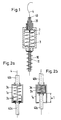
- FIG. 1 The embodiment variant of the invention shown schematically in FIG. 1 is provided for a Bowden tube window lifter, the housing 1 with its guide sleeve 10 being to be assigned directly to a cable deflection piece 43 or a cable outlet of the transmission 44 (see also FIG. 5).
- a piston-like thrust element 2 In the interior of the housing 1 there is a piston-like thrust element 2 with an integrally formed sleeve 20 which serves to guide and to receive the end of a Bowden tube 40.
- a preloaded safety spring 3 is mounted between the thrust element 2 on the one hand and the opposite housing wall on the other hand. It can have a degressive spring characteristic and has at least a preload that corresponds to the adjustment force to be expected. When determining the adjustment force, no extreme conditions (e.g. frozen window pane) should be used, as otherwise the permissible pinching force would be exceeded under normal conditions.
- FIGS. 2a and 2b The embodiment shown in FIGS. 2a and 2b is also provided for Bowden tube window lifters and has a safety spring arranged in the housing 1a, which is supported at one end on the piston-like thrust element 2a.
- the Bowden tubes 40a, 40b are inserted into the receiving ends of the thrust element 2a or the housing 1a.
- a safety spring 3a with a spring characteristic with a negative force-displacement curve is to be used, the pretensioning force being in the spring characteristic range with a negative increase.
- the blocking force was chosen so that it is less than the pre-tensioning force.
- the blocking force is to be understood as the spring force that the Safety spring 3a exerts at maximum deformation, i.e. after the maximum adjustment path has been made available.
- the adjustment distance ⁇ 1 corresponds to the rope length that can be wound up directly by the drive unit.
- the compression of the spring 3 and thus its blocking force is determined by the height (axial extent) of the cup-shaped thrust element 2a. The state shown in FIG. 2a can only be achieved again when the supporting force of the Bowden tube ends 40a, 40b drops below the prestressing force.
- FIG. 3 the structure of a single-strand cable window lifter is shown schematically. It essentially consists of a guide rail 42 with cable deflections 43 at the ends and a drive consisting of a cable drum gear unit 44 and an electric motor 45.
- a closed cable loop 4 is guided over the cable drum gear unit 44 and the two cable deflections 43 and is firmly connected to a driver 5 which is displaceably mounted on the guide rail 42.
- the driver 5 raises or lowers a window pane (not shown).
- the arrow shown in FIG. 3 is intended to indicate that the upper cable deflection 43 is displaceably mounted such that a change in position will lead to a change in the effective length of the cable loop 4.
- a prestressed spring 3 acts in a housing 1b in the direction of displacement of the cable deflection 43. If a sufficiently large rope tension occurs, the spring 3 is compressed and releases a corresponding adjustment path for the rope deflection 43. This shortens the looping distance of the rope loop 4 and the drive can wind up a further rope section, although the driver 5 and the window pane are not raised any further.
- FIG. 4 also shows a single-strand, cable window lifter shown schematically. He uses a special driver 5 'which forms a housing 1c in the area of the nipple chamber for receiving the safety spring 3. A specific example of this is shown in FIG. 6.
- the driver 5 ' essentially consists of the base body 50, the laterally molded housing 51 for receiving the cable nipple 41' and safety spring 3, and the holding jaws 52 extending in the direction of displacement.
- the holding jaws 52 have a spacing of approximately the thickness of the window pane 6 and each have at their free ends a spreading element 57 with internal insertion bevels 520 and a latching opening 55 for receiving a latching element 56.
- the locking element 56 is inserted into a disc hole 60 and presses the spreading elements 57 apart when the locking element 56 is inserted via the insertion bevels 520 until it has reached the assigned locking opening 55. Then the spreading elements 57 overlap the upper contour of the latching element 56 and secure the connection between the window pane 6 and the driver 5 '.
- stops 5 ' are provided on the driver 5' for absorbing forces occurring in the lifting direction and spring elements 54 for compensating for play.
- the cable nipple 41 ' is designed as a support plate for the safety spring 3. It is firmly connected to the cable 4, which extends through the slots 51 through the housing 51.
- the other end of the safety spring 3 biased according to the invention is supported on the upper inner wall of the housing 51.
- the safety spring 3 indicated as a helical spring can also be replaced by another construction principle, preferably by a safety spring with an area with a negative spring characteristic A.
- Curve A shows the preferred course for the invention, which initially shows an approximately proportional increase in the force-displacement diagram, which near the maximum changes into a section of a higher order and then begins to drop monotonously before passing through one At least another monotonously increasing force-displacement curve follows.
- a prestressing force F v is selected at point P 0 , which lies after the maximum MAX in the negative range between MAX and MIN.
- the blocking force F B i.e. the spring force with the maximum permitted spring deformation, should also be in the negative range before the minimum MIN is reached.
- the (symbolically represented) safety spring 3 would suddenly change to the state of point P 1 with a blocking force F B which is smaller than the pretension force F V by the amount - ⁇ F . That is, the pinching force does not increase during the pinching state but decreases.
- the spring travel changes from s 0 to s 1 by the amount ⁇ 1 . If the amount ⁇ 1 is not sufficient to allow movement of the drive that is sufficient for the reliable detection of the pinching condition, the point P 1 can be shifted to the point P 2 without an increase in the Pinching force would occur compared to the initial state. The available travel between s 0 and s 2 is now ⁇ 2 .
- the preload force F V in the area P 0 of the safety spring 3 results from the sum of the expected adjusting force (displacement force) at the location of the safety spring 3 and a safety force to be determined, which must not, however, exceed the permissible clamping force.
- Curve B of the diagram shows an example of a degressive spring characteristic curve.
- a break point after which the force-displacement curve becomes much flatter, so that the increase in force occurs when the necessary spring travel is exceeded a relatively small amount of + ⁇ F 'remains limited, but it is more advantageous to adapt the curve so that the flatter curve area of the spring characteristic B intersects the point P' 0 , whereby the increase in force occurring during the clamping state is somewhat reduced.
- Coil springs previously used generally have a spring characteristic C with a proportional profile. Providing the necessary reaction path with the amount ⁇ " 1 between the points P" 0 and P “ 1 with the pretensioning force F V or the blocking force F" B results in a considerably larger comparison to the spring characteristics B and C during the clamping process Force increase ⁇ F ".
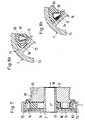
- the safety spring 3b can be arranged, for example, between the stops 72, 80 of gear elements which are connected in the manner of claws, as shown, for example, in FIGS. 7 to 8b.
- the worm wheel 7 has an outer ring 73 with teeth in which a drive worm (not shown) engages. It is connected via a bolt 74 to an inner ring 70 in the form of a shaft 70, on which a cable drum 8 with a cable groove 81 and nipple chamber 82 is mounted. Spoke-shaped stops 72 rise on the floor 74, between which free spaces 71 distributed in the circumferential direction are formed. The claws 80 of the cable drum 8 engage in these free spaces 71.
- FIGS. 8a and 8b show cross sections through the claw area of the gear elements described.
- a prestressed safety spring 3b is supported on the one hand on the claw 80 partially encased by a rubber damper 83 and on the other hand on the spoke-shaped stop 72.
- the spring preload results in a torque that should be sufficient to generate the expected displacement force for the window pane. If the pretensioning force is exceeded, the spring 3b is compressed and there is a relative movement (rotary movement) between the worm wheel 7 and the cable drum 8.
- the difference in rotational angle connected therewith enables the drive worm to be rotated further by at least one turn, which is entirely sufficient for sensing the case of jamming is.
- FIG. 9a shows the schematic representation of a cross arm window lifter 9, the lever arms 91, 92 of which are connected in a universal joint 920.
- the upper ends of the lever arms 91a, 92 are equipped with sliders or rollers 94 and are slidably mounted in the scenes 930 (or profiles) of the lifting rail 93 connected to the window pane 6.
- the lower end of the control arm 92 is guided on the link 950 of the guide rail 95.
- a drive unit consisting of gears 44 'and 45' is available to generate the adjusting force, the pinion 440 of which meshes with the teeth of a segment 910.
- the drive lever consisting of two parts 91a, 91b is mounted in the pivot axis 900 on a base plate (not shown).
- the two arm parts 91a, 91b are also pivotable to a limited extent relative to one another, the pivoting angle being limited by the stop 91aa of the arm part 91a and the stop 91bb of the arm part 91b.
- the stop 91aa is directly assigned to the other arm part 91b as a counter-stop, a prestressed safety spring 3 is supported between the stop 91bb and the arm part 91a.
- the preload of the safety spring 3 is selected so that it is not deformed when normal adjusting forces occur. Only when the displacement resistance of the window pane 6 leads to the pretension of the spring 3 being exceeded does the drive lever buckle in the pivot axis 900. Thus, the drive 44 ', 45' can realize a further apparent adjustment path, although the window pane 6 is no longer movable.
- FIG. 9b essentially corresponds to the exemplary embodiment of FIG. 9a. The only difference is that the drive lever with its arm parts 91'a and 91'b is divided in the universal joint 920.
Landscapes
- Engineering & Computer Science (AREA)
- General Engineering & Computer Science (AREA)
- Mechanical Engineering (AREA)
- Window Of Vehicle (AREA)
- Power-Operated Mechanisms For Wings (AREA)
Applications Claiming Priority (2)
| Application Number | Priority Date | Filing Date | Title |
|---|---|---|---|
| DE19618853 | 1996-05-10 | ||
| DE19618853A DE19618853C1 (de) | 1996-05-10 | 1996-05-10 | Motorisch angetriebener Fensterheber mit elektronischem Einklemmschutz für ein Kraftfahrzeug |
Publications (3)
| Publication Number | Publication Date |
|---|---|
| EP0806538A2 true EP0806538A2 (fr) | 1997-11-12 |
| EP0806538A3 EP0806538A3 (fr) | 1998-06-10 |
| EP0806538B1 EP0806538B1 (fr) | 2000-12-06 |
Family
ID=7793942
Family Applications (1)
| Application Number | Title | Priority Date | Filing Date |
|---|---|---|---|
| EP97250154A Expired - Lifetime EP0806538B1 (fr) | 1996-05-10 | 1997-05-09 | Lève-vitre à moteur avec dispositif anti-pincement pour véhicule automobile |
Country Status (4)
| Country | Link |
|---|---|
| US (1) | US5950365A (fr) |
| EP (1) | EP0806538B1 (fr) |
| DE (2) | DE19618853C1 (fr) |
| ES (1) | ES2153634T3 (fr) |
Cited By (1)
| Publication number | Priority date | Publication date | Assignee | Title |
|---|---|---|---|---|
| DE19881124B4 (de) * | 1997-07-04 | 2013-03-14 | Inteva Products France Sas | Mit Klemmschutzsystem versehener Fensterheber für Kraftfahrzeuge |
Families Citing this family (38)
| Publication number | Priority date | Publication date | Assignee | Title |
|---|---|---|---|---|
| FR2761104B1 (fr) * | 1997-03-21 | 1999-06-25 | Rockwell Lvs | Module de porte de vehicule automobile equipe d'un leve-vitre sans gaine de cable |
| DE19714238A1 (de) * | 1997-04-07 | 1999-01-21 | Bosch Gmbh Robert | Fensterheber für ein Fahrzeugfenster |
| US7059085B1 (en) * | 1998-07-09 | 2006-06-13 | Meritor Light Vehicle Systems France, Llc | Vehicle window arrangement having an angled opening for inserting a cable end during assembly |
| DE19861342B4 (de) * | 1998-08-13 | 2013-10-10 | Küster Holding GmbH | Fensterheber mit Einklemmschutz |
| JP3931453B2 (ja) * | 1998-11-06 | 2007-06-13 | アイシン精機株式会社 | 車両用スライドドアの窓部開閉装置 |
| DE19852977C1 (de) | 1998-11-17 | 1999-10-07 | Brose Fahrzeugteile | Vorrichtung zur Gewährleistung einer Relativbewegung zwischen Teilen eines Seilfensterhebers |
| DE19854993C2 (de) * | 1998-11-23 | 2003-01-30 | Brose Fahrzeugteile | Antriebseinheit für Verstelleinrichtungen in Kraftfahrzeugen |
| EP1133611B1 (fr) | 1999-09-23 | 2003-04-09 | Küster Automotive Door Systems GmbH | Leve-vitre dote d'un dispositif anti-blocage |
| DE19957338A1 (de) * | 1999-11-29 | 2001-05-31 | Thielen Feinmechanik Gmbh & Co | Federwerk |
| FR2821879B1 (fr) * | 2001-03-07 | 2003-12-05 | Meritor Light Vehicle Sys Ltd | Dispositif anti-pincement de leve-vitre a cable |
| US20030066244A1 (en) * | 2001-10-05 | 2003-04-10 | Staser Brian H. | Reconfigurable clamp assembly |
| DE10201604A1 (de) * | 2002-01-16 | 2003-07-24 | Siemens Ag | Aktuator |
| US6678601B2 (en) | 2002-05-31 | 2004-01-13 | Valeo Electrical Systems, Inc. | Motor speed-based anti-pinch control apparatus and method with rough road condition detection and compensation |
| US6794837B1 (en) | 2002-05-31 | 2004-09-21 | Valeo Electrical Systems, Inc. | Motor speed-based anti-pinch control apparatus and method with start-up transient detection and compensation |
| US6822410B2 (en) | 2002-05-31 | 2004-11-23 | Valeo Electrical Systems, Inc. | Motor speed-based anti-pinch control apparatus and method |
| US6788016B2 (en) | 2002-05-31 | 2004-09-07 | Valeo Electrical Systems, Inc. | Motor speed-based anti-pinch control apparatus and method with endzone ramp detection and compensation |
| DE10255461B4 (de) * | 2002-11-25 | 2007-05-16 | Faurecia Innenraum Sys Gmbh | Fensterheberanordnung sowie Kraftfahrzeugtür |
| FR2857716B1 (fr) * | 2003-07-18 | 2005-09-09 | Arvinmeritor Light Vehicle Sys | Tendeur de cable de leve-vitre |
| EP1676971A1 (fr) * | 2004-12-28 | 2006-07-05 | Grupo Antolin Ingenieria, S.A. | Lève-vitre de longue durée |
| US7802401B2 (en) * | 2005-06-30 | 2010-09-28 | Hi-Lex Corporation | Window regulator with improved carrier |
| US7576502B2 (en) * | 2005-07-28 | 2009-08-18 | Arvinmeritor Light Vehicle Systems - France | Method and apparatus for closing a powered closure of a vehicle |
| DE202005013076U1 (de) * | 2005-08-15 | 2006-12-28 | Brose Fahrzeugteile Gmbh & Co. Kommanditgesellschaft, Coburg | Kraftfahrzeugfensterheber |
| US7021001B1 (en) | 2005-08-17 | 2006-04-04 | Schooler Paul T | Anti-pinch power window system |
| DE102006026460A1 (de) * | 2006-06-01 | 2007-12-06 | Brose Fahrzeugteile Gmbh & Co. Kommanditgesellschaft, Coburg | Einklemmschutzsystem für Kraftfahrzeuge |
| DE202007002470U1 (de) | 2007-02-20 | 2008-07-03 | Brose Fahrzeugteile Gmbh & Co. Kommanditgesellschaft, Hallstadt | Getriebeteil für einen Seilfensterheber sowie Antriebseinheit für einen Seilfensterheber |
| DE202007004928U1 (de) | 2007-04-02 | 2008-08-07 | Brose Fahrzeugteile Gmbh & Co. Kommanditgesellschaft, Coburg | Fensterheberantrieb |
| US8096080B2 (en) * | 2007-07-04 | 2012-01-17 | Magna Closures Inc. | Adjustable window regulator lifter plate assembly for a vehicle window |
| DE102008023207A1 (de) * | 2008-05-10 | 2008-12-18 | Daimler Ag | Scheibenführungsanordnung mit einem Fensterheberantrieb und zumindest einem Federelement |
| FR3003510B1 (fr) * | 2013-03-21 | 2015-03-27 | Inteva Products France Sas | Arret de gaine pivotant pour gaine, support, rail de guidage, ensemble, leve-vitre, procede de montage correspondants |
| US9637969B2 (en) * | 2014-08-07 | 2017-05-02 | Hi-Lex Controls, Inc. | Integrated window regulator assembly |
| AT516397B1 (de) * | 2014-11-19 | 2016-05-15 | Miba Sinter Austria Gmbh | Zahnradanordnung |
| JP6076386B2 (ja) * | 2015-01-15 | 2017-02-08 | 株式会社城南製作所 | ウインドレギュレータ |
| JP7029975B2 (ja) * | 2018-02-22 | 2022-03-04 | 株式会社城南製作所 | ウインドレギュレータ |
| DE102018110608A1 (de) * | 2018-05-03 | 2019-11-07 | Kiekert Ag | Kraftfahrzeug-Antriebsanordnung |
| DE102019131324A1 (de) | 2019-06-05 | 2020-12-10 | Eurodoors Production GmbH | Toranlage mit einer Einrichtung zur Kollisionserkennung |
| US20220213729A1 (en) * | 2020-10-30 | 2022-07-07 | Inteva Products, Llc | Dual window regulator with optimized motor configuration |
| DE102023105199A1 (de) * | 2022-03-03 | 2023-09-07 | Inteva Products, Llc | Fensterheber für ein rahmenloses System |
| JP2024092442A (ja) * | 2022-12-26 | 2024-07-08 | 株式会社城南製作所 | ウインドレギュレータ及びストッパ部材の取付け方法 |
Citations (2)
| Publication number | Priority date | Publication date | Assignee | Title |
|---|---|---|---|---|
| FR2693535A1 (fr) * | 1992-07-10 | 1994-01-14 | Rockwell Abs France | Dispositif de sécurité pour lève-vitre électriques de véhicule à câble. |
| EP0604272A1 (fr) * | 1992-12-21 | 1994-06-29 | ROCKWELL BODY AND CHASSIS SYSTEMS - FRANCE, en abrégé: ROCKWELL BCS - FRANCE | Dispositif lève-vitre pour véhicule automobile, équipé d'une sécurité anti-pincement adaptée pour amortir un choc de la vitre contre un obstacle |
Family Cites Families (13)
| Publication number | Priority date | Publication date | Assignee | Title |
|---|---|---|---|---|
| US2324145A (en) * | 1940-12-24 | 1943-07-13 | Detroit Harvester Co | Regulator mechanism for vehicle windows or the like |
| US2400572A (en) * | 1944-01-25 | 1946-05-21 | John B Parsons | Regulator mechanism unit |
| DE2738672C2 (de) * | 1977-08-26 | 1981-12-10 | Metallwerk Max Brose Gmbh & Co, 8630 Coburg | Fensterheber |
| DE3432178C1 (de) * | 1984-08-31 | 1986-01-02 | Brose Fahrzeugteile GmbH & Co KG, 8630 Coburg | Bowdenzug-Fensterheber,insbesondere fuer Kraftfahrzeuge |
| DE3438255C1 (de) * | 1984-10-18 | 1986-06-26 | Brose Fahrzeugteile GmbH & Co KG, 8630 Coburg | Verstellantrieb in einem Kraftfahrzeug mit Dämpfungselement |
| FR2584469A1 (fr) * | 1985-07-05 | 1987-01-09 | Mecanisme Cie Indle | Dispositif tendeur de cable unidirectionnel pour leve-vitre de vehicule automobile |
| CA1297928C (fr) * | 1987-03-18 | 1992-03-24 | Nebojsa Djordjevic | Commande d'ouverture sur cable pour glace d'automobile |
| DE3925864A1 (de) * | 1989-02-03 | 1990-08-09 | Audi Ag | Seilfensterheber fuer kraftfahrzeuge |
| JPH03209042A (ja) * | 1990-01-08 | 1991-09-12 | Koito Mfg Co Ltd | 昇降装置 |
| FR2693569B1 (fr) * | 1992-07-10 | 1994-10-07 | Rockwell Abs France | Dispositif de sécurité pour lève-vitre électriques de véhicule du type à câble coulissant le long d'un rail de guidage. |
| FR2693568B1 (fr) * | 1992-07-10 | 1994-09-30 | Rockwell Abs France | Dispositif de sécurité pour ouvrants électriques de véhicule, notamment lève-vitre et toits ouvrants, et ouvrant incorporant ce dispositif. |
| FR2693589B1 (fr) * | 1992-07-10 | 1994-09-30 | Rockwell Abs France | Dispositif de sécurité pour ouvrants électriques de véhicule, du type à câble d'entraînement d'un organe mobile, notamment lèvre-vitre et toits ouvrants. |
| DE4233549A1 (de) * | 1992-10-01 | 1994-04-21 | Brose Fahrzeugteile | Verfahren und Vorrichtung zum Erfassen der Drehzahl und der Dreheinrichtung eines Drehantriebes |
-
1996
- 1996-05-10 DE DE19618853A patent/DE19618853C1/de not_active Expired - Fee Related
-
1997
- 1997-05-09 EP EP97250154A patent/EP0806538B1/fr not_active Expired - Lifetime
- 1997-05-09 DE DE59702702T patent/DE59702702D1/de not_active Expired - Lifetime
- 1997-05-09 ES ES97250154T patent/ES2153634T3/es not_active Expired - Lifetime
- 1997-05-12 US US08/854,808 patent/US5950365A/en not_active Expired - Lifetime
Patent Citations (2)
| Publication number | Priority date | Publication date | Assignee | Title |
|---|---|---|---|---|
| FR2693535A1 (fr) * | 1992-07-10 | 1994-01-14 | Rockwell Abs France | Dispositif de sécurité pour lève-vitre électriques de véhicule à câble. |
| EP0604272A1 (fr) * | 1992-12-21 | 1994-06-29 | ROCKWELL BODY AND CHASSIS SYSTEMS - FRANCE, en abrégé: ROCKWELL BCS - FRANCE | Dispositif lève-vitre pour véhicule automobile, équipé d'une sécurité anti-pincement adaptée pour amortir un choc de la vitre contre un obstacle |
Cited By (1)
| Publication number | Priority date | Publication date | Assignee | Title |
|---|---|---|---|---|
| DE19881124B4 (de) * | 1997-07-04 | 2013-03-14 | Inteva Products France Sas | Mit Klemmschutzsystem versehener Fensterheber für Kraftfahrzeuge |
Also Published As
| Publication number | Publication date |
|---|---|
| EP0806538A3 (fr) | 1998-06-10 |
| ES2153634T3 (es) | 2001-03-01 |
| EP0806538B1 (fr) | 2000-12-06 |
| DE59702702D1 (de) | 2001-01-11 |
| DE19618853C1 (de) | 1997-08-14 |
| US5950365A (en) | 1999-09-14 |
Similar Documents
| Publication | Publication Date | Title |
|---|---|---|
| DE19618853C1 (de) | Motorisch angetriebener Fensterheber mit elektronischem Einklemmschutz für ein Kraftfahrzeug | |
| EP0701649B1 (fr) | Leve-vitre manuel a cable | |
| EP1904711A1 (fr) | Arbre d'enroulement pour un systeme de store | |
| EP1626152A1 (fr) | Protection solaire pour un toit vitré | |
| DE102007012281A1 (de) | Automatisch betätigbares Seitenfensterrollo | |
| EP0937853A2 (fr) | Dispositif de commande pour une porte coulissante, en particulier pour véhicules | |
| EP0775242B1 (fr) | Leve-vitre a moteur | |
| EP1913221B1 (fr) | Element de transmission de force, leve-vitre, et porte de vehicule automobile equipee de ce leve-vitre | |
| DE202004014652U1 (de) | Fahrzeugtür mit einem Fensterheber | |
| EP1641993B1 (fr) | Dispositif de deflexion pour leve-vitre de vehicule automobile | |
| EP2757219B1 (fr) | Dispositif d'entraînement de porte coulissante | |
| DE202008009763U1 (de) | Fahrzeugrollo | |
| DE3907175C1 (fr) | ||
| DE102008026707A1 (de) | Drehwellenanordnung für ein Tor, insbesondere für ein Rolltor, und ein solches Tor | |
| DE69832976T2 (de) | Fensterheber mit einer verbesserten kurbeleinheit | |
| WO2006063565A1 (fr) | Store pour vitre de vehicule | |
| DE102020213193A1 (de) | Seilantriebsvorrichtung eines Kraftfahrzeugs | |
| DE102004043000A1 (de) | Fahrzeugtür | |
| EP0529591B1 (fr) | Dispositif de store, de préference pour lunettes arrières de véhicules | |
| DE29914588U1 (de) | Vorrichtung zum Bewegen einer Gardine | |
| EP1849635B1 (fr) | Store de fenêtre à installer sur la partie intérieure de la fenêtre d'un véhicule automobile | |
| DE60212029T2 (de) | Fensterheber mit Blockierung des Mitnehmers und Montageverfahren | |
| DE102015107449A1 (de) | Schließhilfsanordnung | |
| DE19854993C2 (de) | Antriebseinheit für Verstelleinrichtungen in Kraftfahrzeugen | |
| DE202007012206U1 (de) | Fensterrollo für ein Fahrzeugfenster |
Legal Events
| Date | Code | Title | Description |
|---|---|---|---|
| PUAI | Public reference made under article 153(3) epc to a published international application that has entered the european phase |
Free format text: ORIGINAL CODE: 0009012 |
|
| AK | Designated contracting states |
Kind code of ref document: A2 Designated state(s): DE ES FR GB IT SE |
|
| PUAL | Search report despatched |
Free format text: ORIGINAL CODE: 0009013 |
|
| AK | Designated contracting states |
Kind code of ref document: A3 Designated state(s): DE ES FR GB IT SE |
|
| 17P | Request for examination filed |
Effective date: 19980508 |
|
| 17Q | First examination report despatched |
Effective date: 19991112 |
|
| GRAG | Despatch of communication of intention to grant |
Free format text: ORIGINAL CODE: EPIDOS AGRA |
|
| GRAG | Despatch of communication of intention to grant |
Free format text: ORIGINAL CODE: EPIDOS AGRA |
|
| GRAH | Despatch of communication of intention to grant a patent |
Free format text: ORIGINAL CODE: EPIDOS IGRA |
|
| GRAH | Despatch of communication of intention to grant a patent |
Free format text: ORIGINAL CODE: EPIDOS IGRA |
|
| GRAA | (expected) grant |
Free format text: ORIGINAL CODE: 0009210 |
|
| AK | Designated contracting states |
Kind code of ref document: B1 Designated state(s): DE ES FR GB IT SE |
|
| REF | Corresponds to: |
Ref document number: 59702702 Country of ref document: DE Date of ref document: 20010111 |
|
| ET | Fr: translation filed | ||
| GBT | Gb: translation of ep patent filed (gb section 77(6)(a)/1977) |
Effective date: 20010206 |
|
| REG | Reference to a national code |
Ref country code: ES Ref legal event code: FG2A Ref document number: 2153634 Country of ref document: ES Kind code of ref document: T3 |
|
| ITF | It: translation for a ep patent filed | ||
| PLBE | No opposition filed within time limit |
Free format text: ORIGINAL CODE: 0009261 |
|
| STAA | Information on the status of an ep patent application or granted ep patent |
Free format text: STATUS: NO OPPOSITION FILED WITHIN TIME LIMIT |
|
| 26N | No opposition filed | ||
| REG | Reference to a national code |
Ref country code: GB Ref legal event code: IF02 |
|
| PGFP | Annual fee paid to national office [announced via postgrant information from national office to epo] |
Ref country code: SE Payment date: 20030507 Year of fee payment: 7 |
|
| PG25 | Lapsed in a contracting state [announced via postgrant information from national office to epo] |
Ref country code: SE Free format text: LAPSE BECAUSE OF NON-PAYMENT OF DUE FEES Effective date: 20040510 |
|
| EUG | Se: european patent has lapsed | ||
| PGFP | Annual fee paid to national office [announced via postgrant information from national office to epo] |
Ref country code: ES Payment date: 20110617 Year of fee payment: 15 |
|
| PGFP | Annual fee paid to national office [announced via postgrant information from national office to epo] |
Ref country code: GB Payment date: 20110504 Year of fee payment: 15 |
|
| GBPC | Gb: european patent ceased through non-payment of renewal fee |
Effective date: 20120509 |
|
| PG25 | Lapsed in a contracting state [announced via postgrant information from national office to epo] |
Ref country code: GB Free format text: LAPSE BECAUSE OF NON-PAYMENT OF DUE FEES Effective date: 20120509 |
|
| REG | Reference to a national code |
Ref country code: ES Ref legal event code: FD2A Effective date: 20130821 |
|
| PG25 | Lapsed in a contracting state [announced via postgrant information from national office to epo] |
Ref country code: ES Free format text: LAPSE BECAUSE OF NON-PAYMENT OF DUE FEES Effective date: 20120510 |
|
| REG | Reference to a national code |
Ref country code: FR Ref legal event code: PLFP Year of fee payment: 19 |
|
| PGFP | Annual fee paid to national office [announced via postgrant information from national office to epo] |
Ref country code: DE Payment date: 20150531 Year of fee payment: 19 |
|
| PGFP | Annual fee paid to national office [announced via postgrant information from national office to epo] |
Ref country code: IT Payment date: 20150515 Year of fee payment: 19 Ref country code: FR Payment date: 20150508 Year of fee payment: 19 |
|
| REG | Reference to a national code |
Ref country code: DE Ref legal event code: R119 Ref document number: 59702702 Country of ref document: DE |
|
| PG25 | Lapsed in a contracting state [announced via postgrant information from national office to epo] |
Ref country code: IT Free format text: LAPSE BECAUSE OF NON-PAYMENT OF DUE FEES Effective date: 20160509 |
|
| REG | Reference to a national code |
Ref country code: FR Ref legal event code: ST Effective date: 20170131 |
|
| PG25 | Lapsed in a contracting state [announced via postgrant information from national office to epo] |
Ref country code: DE Free format text: LAPSE BECAUSE OF NON-PAYMENT OF DUE FEES Effective date: 20161201 Ref country code: FR Free format text: LAPSE BECAUSE OF NON-PAYMENT OF DUE FEES Effective date: 20160531 |