EP0796749A2 - Nutzfahrzeug - Google Patents
Nutzfahrzeug Download PDFInfo
- Publication number
- EP0796749A2 EP0796749A2 EP97104599A EP97104599A EP0796749A2 EP 0796749 A2 EP0796749 A2 EP 0796749A2 EP 97104599 A EP97104599 A EP 97104599A EP 97104599 A EP97104599 A EP 97104599A EP 0796749 A2 EP0796749 A2 EP 0796749A2
- Authority
- EP
- European Patent Office
- Prior art keywords
- value
- angular velocity
- controller
- vehicle
- rear axle
- Prior art date
- Legal status (The legal status is an assumption and is not a legal conclusion. Google has not performed a legal analysis and makes no representation as to the accuracy of the status listed.)
- Granted
Links
Images


Classifications
-
- B—PERFORMING OPERATIONS; TRANSPORTING
- B60—VEHICLES IN GENERAL
- B60G—VEHICLE SUSPENSION ARRANGEMENTS
- B60G17/00—Resilient suspensions having means for adjusting the spring or vibration-damper characteristics, for regulating the distance between a supporting surface and a sprung part of vehicle or for locking suspension during use to meet varying vehicular or surface conditions, e.g. due to speed or load
- B60G17/005—Suspension locking arrangements
-
- B—PERFORMING OPERATIONS; TRANSPORTING
- B66—HOISTING; LIFTING; HAULING
- B66F—HOISTING, LIFTING, HAULING OR PUSHING, NOT OTHERWISE PROVIDED FOR, e.g. DEVICES WHICH APPLY A LIFTING OR PUSHING FORCE DIRECTLY TO THE SURFACE OF A LOAD
- B66F9/00—Devices for lifting or lowering bulky or heavy goods for loading or unloading purposes
- B66F9/06—Devices for lifting or lowering bulky or heavy goods for loading or unloading purposes movable, with their loads, on wheels or the like, e.g. fork-lift trucks
- B66F9/075—Constructional features or details
- B66F9/07586—Suspension or mounting of wheels on chassis
-
- B—PERFORMING OPERATIONS; TRANSPORTING
- B60—VEHICLES IN GENERAL
- B60G—VEHICLE SUSPENSION ARRANGEMENTS
- B60G21/00—Interconnection systems for two or more resiliently-suspended wheels, e.g. for stabilising a vehicle body with respect to acceleration, deceleration or centrifugal forces
- B60G21/02—Interconnection systems for two or more resiliently-suspended wheels, e.g. for stabilising a vehicle body with respect to acceleration, deceleration or centrifugal forces permanently interconnected
- B60G21/06—Interconnection systems for two or more resiliently-suspended wheels, e.g. for stabilising a vehicle body with respect to acceleration, deceleration or centrifugal forces permanently interconnected fluid
- B60G21/073—Interconnection systems for two or more resiliently-suspended wheels, e.g. for stabilising a vehicle body with respect to acceleration, deceleration or centrifugal forces permanently interconnected fluid between wheels on the same axle but on different sides of the vehicle, i.e. the left and right wheel suspensions being interconnected
-
- B—PERFORMING OPERATIONS; TRANSPORTING
- B60—VEHICLES IN GENERAL
- B60G—VEHICLE SUSPENSION ARRANGEMENTS
- B60G21/00—Interconnection systems for two or more resiliently-suspended wheels, e.g. for stabilising a vehicle body with respect to acceleration, deceleration or centrifugal forces
- B60G21/08—Interconnection systems for two or more resiliently-suspended wheels, e.g. for stabilising a vehicle body with respect to acceleration, deceleration or centrifugal forces characterised by use of gyroscopes
-
- B—PERFORMING OPERATIONS; TRANSPORTING
- B60—VEHICLES IN GENERAL
- B60G—VEHICLE SUSPENSION ARRANGEMENTS
- B60G9/00—Resilient suspensions of a rigid axle or axle housing for two or more wheels
- B60G9/02—Resilient suspensions of a rigid axle or axle housing for two or more wheels the axle or housing being pivotally mounted on the vehicle, e.g. the pivotal axis being parallel to the longitudinal axis of the vehicle
-
- B—PERFORMING OPERATIONS; TRANSPORTING
- B60—VEHICLES IN GENERAL
- B60G—VEHICLE SUSPENSION ARRANGEMENTS
- B60G2200/00—Indexing codes relating to suspension types
- B60G2200/30—Rigid axle suspensions
- B60G2200/32—Rigid axle suspensions pivoted
- B60G2200/322—Rigid axle suspensions pivoted with a single pivot point and a straight axle
-
- B—PERFORMING OPERATIONS; TRANSPORTING
- B60—VEHICLES IN GENERAL
- B60G—VEHICLE SUSPENSION ARRANGEMENTS
- B60G2204/00—Indexing codes related to suspensions per se or to auxiliary parts
- B60G2204/10—Mounting of suspension elements
- B60G2204/12—Mounting of springs or dampers
- B60G2204/128—Damper mount on vehicle body or chassis
-
- B—PERFORMING OPERATIONS; TRANSPORTING
- B60—VEHICLES IN GENERAL
- B60G—VEHICLE SUSPENSION ARRANGEMENTS
- B60G2204/00—Indexing codes related to suspensions per se or to auxiliary parts
- B60G2204/40—Auxiliary suspension parts; Adjustment of suspensions
- B60G2204/46—Means for locking the suspension
-
- B—PERFORMING OPERATIONS; TRANSPORTING
- B60—VEHICLES IN GENERAL
- B60G—VEHICLE SUSPENSION ARRANGEMENTS
- B60G2300/00—Indexing codes relating to the type of vehicle
- B60G2300/02—Trucks; Load vehicles
- B60G2300/022—Fork lift trucks, Clark
-
- B—PERFORMING OPERATIONS; TRANSPORTING
- B60—VEHICLES IN GENERAL
- B60G—VEHICLE SUSPENSION ARRANGEMENTS
- B60G2400/00—Indexing codes relating to detected, measured or calculated conditions or factors
- B60G2400/60—Load
- B60G2400/61—Load distribution
-
- B—PERFORMING OPERATIONS; TRANSPORTING
- B60—VEHICLES IN GENERAL
- B60G—VEHICLE SUSPENSION ARRANGEMENTS
- B60G2400/00—Indexing codes relating to detected, measured or calculated conditions or factors
- B60G2400/60—Load
- B60G2400/63—Location of the center of gravity
-
- B—PERFORMING OPERATIONS; TRANSPORTING
- B60—VEHICLES IN GENERAL
- B60G—VEHICLE SUSPENSION ARRANGEMENTS
- B60G2800/00—Indexing codes relating to the type of movement or to the condition of the vehicle and to the end result to be achieved by the control action
- B60G2800/01—Attitude or posture control
- B60G2800/012—Rolling condition
-
- B—PERFORMING OPERATIONS; TRANSPORTING
- B60—VEHICLES IN GENERAL
- B60G—VEHICLE SUSPENSION ARRANGEMENTS
- B60G2800/00—Indexing codes relating to the type of movement or to the condition of the vehicle and to the end result to be achieved by the control action
- B60G2800/90—System Controller type
- B60G2800/95—Automatic Traction or Slip Control [ATC]
-
- B—PERFORMING OPERATIONS; TRANSPORTING
- B60—VEHICLES IN GENERAL
- B60Y—INDEXING SCHEME RELATING TO ASPECTS CROSS-CUTTING VEHICLE TECHNOLOGY
- B60Y2200/00—Type of vehicle
- B60Y2200/10—Road Vehicles
- B60Y2200/15—Fork lift trucks, Industrial trucks
-
- B—PERFORMING OPERATIONS; TRANSPORTING
- B60—VEHICLES IN GENERAL
- B60Y—INDEXING SCHEME RELATING TO ASPECTS CROSS-CUTTING VEHICLE TECHNOLOGY
- B60Y2400/00—Special features of vehicle units
- B60Y2400/86—Suspension systems
Definitions
- the present invention relates to axle supporting apparatus for industrial vehicles, and more particularly, to an apparatus for locking swingable axles of industrial vehicles.
- a typical forklift truck has a rear axle that is supported by a body frame.
- the rear axle is swung with respect to the body frame by lateral acceleration, or centrifugal force, that is produced when the traveling forklift truck changes directions. This degrades the traveling stability of the forklift truck. Thus, the traveling speed of the forklift truck must he decreased when changing directions.
- Japanese Unexamined Patent Publication No. 58-211903 describes a forklift truck that locks the swinging of an axle when the truck turns.
- the forklift truck has a detecting means that detects centrifugal force when the truck is turned. When the centrifugal force becomes greater than a predetermined level, the swinging of the axle with respect to the body frame is restricted. In other words, the axle is locked.
- This enables stable turning of the forklift truck without having to slow down the vehicle.
- the centrifugal force, for an instantant is less than the predetermined level. This releases the locking of the axle regardless of the vehicle changing directions. As a result, the forklift truck becomes unstable when successively turned in different directions.
- Japanese Unexamined Patent Publication No. 58-214406 describes a forklift truck that locks its axle when the rotated angle of a steering wheel and the speed of the vehicle become greater than predetermined values. However, when the vehicle is successively turned in different directions, for an instant, the rotated angle of the steering wheel becomes smaller than the predetermined angle. Thus, in the same manner as the forklift truck of Publication No. 58-211903, this releases the locking of the axle and causes instability.
- one of the wheels may be lifted from the ground depending on the weight of the object held by the forks when the axles are locked during turning. For example, when a heavy object is held on the forks, the center of gravity of the vehicle is displaced toward the front of the forklift truck. This may lift one of the rear wheels from the ground if one of the axles are locked. If the axles are locked when a relatively light object is held on the forks, the balance weight provided at the rear of the vehicle may cause one or the front wheels to raise from the ground.
- torque is transmitted to the front wheels to drive forklift trucks.
- the steering angle is transmitted to the roar wheels to steer the vehicle. Accordingly, if the rear axle is locked when a relatively light object is held on the forks, one of the front wheels, which function as the drive wheels, may be lifted away from the ground. This decreases traction between the front wheels and the ground. As a result, the driving force of the vehicle becomes insufficient. This hinders smooth operation of the forklift truck.
- the center of gravity which is near the front of the vehicle, increases the traction force of the front wheels. Accordingly, the locking of the axle does not affect the driving force of the vehicle.
- the center of gravity is near the front of the vehicle, the vehicle tends to swing in a forward direction.
- the forklift truck becomes unstable when lifting and lowering objects and when traveling with the heavy object held on the forks. This tendency is stronger if the object is held at a high position, which raises the center of gravity.
- a further objective of the present invention is to provide an industrial vehicle that is capable of lifting and lowering objects in a stable manner.
- an improved control apparatus for an industrial vehicle includes a rear axle, said rear axle being swingable upon a straight travel of the vehicle and fixed upon a turning of the vehicle.
- the apparatus comprises holding means for selectively locking and unlocking the rear axle, memory means for storing a first value and a second value of an angular velocity rate , wherein said angular velocity rate represents an angular velocity per a unit time, wherein said first value is predetermined to indicate turning of the vehicle when the angular velocity rate is greater than the first value, and wherein said second value is predetermined to indicate the straight travel of the vehicle when the angular velocity rate is smaller than the second value and control means for selectively activating and deactivating the holding means, said control means activates the holding means to lock the rear axle when the angular velocity rate is greater than the first value, said control means deactivates the holding means to unlock the rear axle when the angular velocity rate is kept smaller than the second value for a predetermined time period after the angular velocity rate has become smaller
- FIG. 1 An industrial vehicle, or forklift truck 1 having a body frame 1a is shown in Fig. 1.
- a pair of left and right outer masts 2 are mounted on the front of the forklift truck 1.
- a pair of inner masts 3 are provided between the outer masts 2.
- a fork 4 is mounted on each inner mast 2. The fork 4 is lifted and lowered with respect to the associated inner mast 2.
- a tilting cylinder 5 having a body 5a and a cylinder rod 5b is provided for each outer mast 2.
- the body 5a is coupled to the body frame 1a while the cylinder rod 5b is coupled to the associated outer mast 2.
- the outer masts 2 and the forks 4 are tilted by the tilting cylinders 5.
- a lifting cylinder 6 having a body 6 and a rod 6b is provided for each inner mast 2.
- the body 6a is coupled to the body frame 1a while the cylinder rod 6b is coupled to the associated inner mast 2.
- the inner masts 3 are lifted and lowered by the lifting cylinders 6,
- a pair of front wheels 7 are mounted at the front portion of the frame 1a. As shown in Fig. 4, the front wheels 7 are connected to an engine E by means of a differential gear U and a transmission D. Hence, each front wheel 7 is driven by the engine E.
- a pair of rear wheels 8 are mounted at the rear portion of the frame 1.
- a structure for connecting the rear wheels 8 is shown in Fig. 2.
- a rear axle 11 is provided at the lower rear portion of the frame 1a extending between the left and right sides of the frame 1a.
- the rear axle 11 is pivotal about a center pin 11a.
- the rear wheels 8 are mounted on the ends of the rear axle 11. The direction of the rear wheels 8 is changed by turning a steering wheel 10, which is installed in a driver's compartment 9.
- a damper, or shock absorber 12 is connected between the body frame 1a and the rear axle 11.
- the shock absorber 12 is a double action hydraulic cylinder and absorbs the force that is applied to the rear wheels 8.
- the shock absorber 12 includes a cylindrical body 12a, a piston 12b accommodated in the body 12a, and a piston rod 12c connected to the piston 12b. The distal end of the piston rod 12c is connected to the rear axle 11.
- a first compartment R1 and a second compartment R2 are defined in the shock absorber 12 by the piston 12b.
- a first oil passage P1 is connected to the first chamber R1 while a second oil passage P2 is connected to the second chamber R2.
- the first and second oil passages P1, P2 are connected to an electromagnetic switching valve 13.
- the switching valve 13 includes a body and a spool.
- the spool has a connecting portion 14 and a disconnecting portion 15.
- a third oil passage P3 and a fourth oil passage P4 are connected to the switching valve 13.
- the third oil passage P3 is connected with the fourth oil passage P4.
- the fourth oil passage P4 is connected to an accumulator 16 in which hydraulic oil is reserved.
- a throttle valve 17 is provided in the second oil passage P2.
- the spool moves with respect to the body and selectively connects the connecting portion 14 and the disconnecting portion 15 with the oil passages P1 to P4.
- the connecting portion 14 is connected to the oil passages P1 to P4
- the first oil passage P1 is communicated with the third oil passage P3
- the second oil passage P2 is communicated with the fourth oil passage P4.
- the first and second chambers R1, R2 are communicated with the accumulator 16. This permits hydraulic oil to flow in and out of the first and second chambers R1, R2.
- the shock absorber 12 enables pivoting of the rear axle 11.
- the disconnecting portion 15 is connected with the oil passages P1 to P4, the oil passages P1 to P4 are disconnected from one another.
- the piston 12b of the shock absorber 12 is locked.
- the shock absorber 12 prohibits pivoting of the rear axle 11.
- a balance weight 19 is mounted on the rear of the forklift truck 1.
- a piezo-electric sensor, or gyroscope 20, is arranged on the balance weight 19
- the gyroscope 20 detects the angular velocity, or yaw rate ⁇ of the forklift truck 1 when changing directions.
- an acceleration sensor 21 is arranged on an instrument panel W provided in the driver's compartment 9. The acceleration sensor 21 is located midway between the front wheels 7. Actual lateral acceleration, or actual centrifugal force Fa, that is produced when the forklift truck 1 changes directions is detected by the acceleration sensor 21.
- a limit switch 24 is arranged at the upper portion of the outer mast 2 to detect the vertical position of the associated fork 4.
- the limit switch 24 is located at a position that is lower than the top end of the outer mast 2 by one fourth the length of the mast 2.
- a pressure sensor 25 is provided at the bottom end of the lifting cylinder 6 to detect the hydraulic pressure of the hydraulic oil that acts on the lifting cylinder 6.
- a steering angle sensor 22 is arranged on one of the rear wheels 8 to detect the steering angle ⁇ of the rear wheels 8.
- a vehicle speed sensor 23 is provided in the forklift truck 1 to detect the rotating speed of the differential gear U, or the traveling speed v of the forklift truck 1.
- the controller 31 has a memory 31a and a timer 31b that are included in a central processing unit (CPU), a read only memory (ROM), and other parts.
- the controller 31 also has an input terminal and an output terminal.
- the gyroscope 20, the acceleration sensor 21, the steering angle sensor 22, the vehicle speed sensor 23, the limit switch 24, and the pressure sensor 25 are connected to the input terminal.
- the electromagnetic switching valve 13 is connected to the output terminal of the controller 31.
- the gyroscope 20 sends an angular velocity signal, which corresponds to the detected yaw rate ⁇ , to the controller 31.
- the acceleration sensor 21 sends an actual centrifugal force signal, which corresponds to the detected actual centrifugal force Fa, to the controller 31.
- the steering angle sensor 22 sends a steering angle signal, which corresponds to the detected steering angle ⁇ of the rear wheels 8, to the controller 31.
- the vehicle speed sensor 23 sends a speed signal, which corresponds to the detected speed v of the forklift truck 1, to the controller 31.
- the limit switch 24 sends an activated signal to the controller 31 when actuated as the associated fork 4 is lifted above a reference height Zref.
- the reference height Zref is located at a position that is lower than the top end of the outer mast 2 by approximately one fourth the length of the outer mast 2.
- the pressure sensor 25 sends a hydraulic pressure signal, which corresponds to the detected hydraulic pressure y applied to the lifting cylinder 6, to the controller 31.
- the controller 31 Based on the angular velocity signal sent from the gyroscope 20, the controller 31 computes the angular velocity altering rate, or the yaw rate altering rate ⁇ / ⁇ T.
- the altering rate ⁇ / ⁇ T corresponds to the angular acceleration.
- the controller 31 obtains the altering rate ⁇ / ⁇ T by differentiating the yaw rate ⁇ with respect to time.
- the controller 31 determines lateral acceleration based on centrifugal force.
- the controller 31 computes centrifugal force based on the traveling speed signal from the vehicle speed sensor 23 and the angular velocity signal from the gyroscope 20.
- the computed centrifugal force Fb differs from the actual centrifugal force detected by the acceleration sensor 21. Thus, there is a slight difference between the values of the actual centrifugal force Fa and the computed centrifugal force Fb.
- Reference values of the yaw rate altering rate ⁇ / ⁇ T are stored in the memory 31a of the controller 31.
- the reference rate values include a maximum reference value Kmax, which is referred to when the rate ⁇ / ⁇ T increases, and a minimum reference value Kmin, which is referred to when the rate ⁇ / ⁇ T decreases.
- the controller 31 starts the output of a locking signal when the value of the computed altering rate ⁇ / ⁇ T changes from a value equal to or smaller than the maximum reference value Kmax to a value greater than the maximum reference value Kmax.
- the controller 31 compares the altering rate ⁇ / ⁇ T with the minimum reference value Kmin. If the value of the altering rate ⁇ / ⁇ T changes from a value equal to or greater than the minimum reference value Kmin to a value smaller than the minimum reference value Kmin, the controller 31 stops the output of the locking signal.
- the controller 31 waits for a predetermined time length T to elapse before stopping the output of the locking signal. More specifically, a timer 31b starts measuring time when the value of the altering rate ⁇ / ⁇ T changes from a value equal to or greater than the minimum reference value Kmin to a value smaller than the minimum reference value Kmin. When the measured time reaches the time length T, the controller 31 stops the output of the locking signal. The timer 31b is controlled by the controller 31 so as to stop measuring time when the value of the altering rate ⁇ / ⁇ T becomes equal to or greater than the minimum reference value Kmin.
- Reference values of the centrifugal force acting on the forklift truck 1 are stored in the memory 31a of the controller 31.
- the reference values include a centrifugal force maximum reference value Hmax, which is referred to when the centrifugal force increases, and a centrifugal force minimum reference value Hmin, which is referred to when the centrifugal force decreases.
- the controller 31 starts outputting a locking signal when the absolute value of the computed centrifugal force Fb changes from a value equal to or smaller than the maximum reference value Hmax to a value greater than the maximum reference value Hmax.
- the controller 31 stops the locking signal if the absolute value of the computed centrifugal force Fb becomes smaller than the minimum reference value Hmin.
- the controller 31 determines the weight of the load on the forks 4 based on the signal from the pressure sensor 25.
- the controller 31 further computes and locates the center of gravity G (Fig. 6) of the forklift truck 1 based on the weight of the load.
- the center of gravity G corresponds to the center of gravity of the combined mass of the vehicle and the load.
- the controller computes the center of gravity G under the assumption that the inclination of the outer masts 1 is maximum as shown in the dotted lines of Fig. 5.
- a reference pressure value Nref of the hydraulic pressure y applied to the lifting cylinder 6 is stored in the memory 31a of the controller 31.
- the controller 31 computes the hydraulic pressure y applied to the lifting cylinder 6 based on the detecting signal from the pressure sensor 25 when receiving an activated signal from the limit switch 24. If the hydraulic pressure y is equal to or greater than the reference pressure value Nref, the controller 31 sends a locking signal to the electromagnetic switching valve 13.
- controller 31 sends a locking signal to the switching valve 13 when any one of the following six conditions is satisfied:
- the electromagnetic switching valve 13 has a solenoid that is excited by the locking signal. This causes the disconnecting portion 15 of the switching valve 13 to be selectively connected with the oil passages P1 to P4. As a result, the switching valve 13 closes the first and second oil passages P1, P2 and locks the rear axle 11 with the shock absorber 12. When not receiving the locking signal, the solenoid is de-excited. This causes the connecting portion 14 to be selectively connected to the oil passages P1 to P4. As a result, the switching valve 13 permits hydraulic oil to flow in and out of the first and second chambers R1, R2. In such state, the body frame 1a is swingable with respect to the rear axle 11.
- the controller 31 locks the rear axle 11 with the switching valve 13 in accordance with the flowchart illustrated in Figs. 8(A) and 8(B). It is presumed here that the locking signal is not being output from the controller 31 and that the rear axle 11 is swingable when the controller 31 enters the control processing of Fig. 8(A).
- the character "S” stands for "step.”
- the controller 31 reads the traveling speed v of the forklift truck 1 based on the traveling speed signal sent from the vehicle speed sensor 23.
- the controller 31 reads the yaw rate ⁇ based on the angular velocity signal sent from the gyroscope 20.
- the controller 31 obtains the computed centrifugal force Fb by applying the traveling speed v and the yaw rate ⁇ to the equation (1).
- the controller 31 computes the yaw rate altering rate ⁇ / ⁇ T based on the yaw rate ⁇ .
- the controller 31 has a low pass filter function, which is used in step 105 to eliminate high frequency noise from the altering rate ⁇ / ⁇ T.
- the controller 31 determines whether the absolute value of the computed centrifugal force Fb (
- step 108 the controller 31 determines whether the absolute value
- the controller 31 determines whether the yaw rate altering rate ⁇ / ⁇ T is greater than the maximum reference value Kmax. When it is determined that the altering rate ⁇ / ⁇ T is greater than the maximum reference value Kmax, the controller 31 proceeds to step 111 and outputs the locking signal to the switching valve 13. This fixes the shock absorber 12 and holds the rear axle 11 in a locked state. The controller 31 then returns to step 101 and repeats the execution of the above steps. If it is determined that the altering rate ⁇ / ⁇ T is equal to or less than the maximum reference value Kmax in step 110, the controller 31 proceeds to step 112.
- the controller 31 determines whether the altering rate ⁇ / ⁇ T is smaller than the minimum reference value Kmin. When it is determined that the altering rate ⁇ / ⁇ T is smaller than the minimum reference value Kmin, the controller 31 proceeds to step 113 and determines whether the time measured by the timer 31b has reached the predetermined time length T. When it is determined that the time length T has not yet elapsed, the controller 31 returns to step 101 and repeats the above steps. If it is determined that the time length T has elapsed, the controller 31 proceeds to step 114 and stops the output of the looking signal. Afterwards, the controller 31 returns to step 101.
- the controller 31 then proceeds to step 112 and determines whether the value of the hydraulic pressure y, which is obtained based on the signal from the pressure senior 25, is equal to or greater than the reference pressure value Nref. When it is determined that the hydraulic pressure y is equal to or greater than the reference value Nref, the controller 31 proceeds to step 116 and determines whether the activated signal is being output from the limit switch 24. If it is determined that the activated signal is being output from the limit switch 24, the controller 31 proceeds to step 118 and continues to output the locking signal.
- step 115 If it is determined that the value of the hydraulic pressure y is smaller than the reference value Nref in step 115, the controller 31 proceeds to step 117 and stops outputting the locking signal. The controller 31 also proceeds to step 117 and stops outputting the locking signal if it is determined that the activated signal is not being output from the limit switch 24 in step 116.
- the value of the steering angle ⁇ increases.
- the values of the yaw rate ⁇ , the computed centrifugal force Fb, the actual centrifugal force Fa, and the yew rate altering rate ⁇ / ⁇ T are each increased accordingly.
- the altering rate ⁇ / ⁇ T is the first to increase among these values and becomes greater than the maximum reference value Kmax.
- the controller 31 locks the rear axle 11 when the altering rate ⁇ / ⁇ T becomes greater than the maximum reference value Kmax.
- the value of the computed centrifugal force Fb is smaller than the maximum reference value Hmax. Accordingly, when the turning of the forklift truck 1 begins, the rear axle 11 is locked by the altering rate ⁇ / ⁇ T before being locked by the computed centrifugal force Fb.
- the values of the yaw rate ⁇ , the computed centrifugal force Fb, and the actual centrifugal force Fa are each increased accordingly. This causes the absolute value of the computed centrifugal force
- the altering rate ⁇ / ⁇ T is greater than the maximum reference value Kmax and the rear axle 11 is held in a locked state.
- the controller 31 outputs the locking signal since the computed centrifugal force Fb is greater than the maximum reference value Hmax. Accordingly, the rear axle 11 remains in a locked state.
- the above processing is executed in the same manner when the forklift truck 1 is steered to the left from a state in which it is traveling straight.
- the altering rate ⁇ / ⁇ T first becomes greater than the maximum reference value Kmax and locks the rear axle 11.
- the altering rate ⁇ / ⁇ T then becomes smaller than the minimum reference value Kmin.
- is greater than the maximum reference value Hmax, the rear axle 11 remains in a locked state.
- a further decrease of the steering angle ⁇ causes the computed centrifugal force Fb to become smaller than the minimum reference value Kmin.
- the controller 31 continues to output the locking signal since the altering rate ⁇ / ⁇ T is greater than the maximum reference value Kmax.
- the altering rate ⁇ / ⁇ T is maximum when the steering angle ⁇ becomes close to zero degrees.
- the forklift truck 1 begins to turn left as the value of the steering angle ⁇ reaches zero degrees and then further decreases.
- the decrease in the value of the steering angle ⁇ causes further decrease of the values of the yaw rate ⁇ and the computed centrifugal force Fb.
- the values of the yaw rate ⁇ and the computed centrifugal force Fb become negative and continue to further decrease.
- becomes greater than the maximum reference value Hmax.
- the altering rate ⁇ / ⁇ T is equal to or greater than the minimum reference value Kmin. Since the conditions of
- a further decrease of the steering angle ⁇ causes the altering rate ⁇ / ⁇ T to become smaller than the minimum reference value Kmin.
- the controller 31 continues to output the locking signal and keeps the rear axle 11 in a locked state.
- the locking, signal is continued prior to the expiration of the predetermined time length T, which is measured from when the altering rate ⁇ / ⁇ T became smaller than the minimum reference value Kmin.
- the locking signal is continued as long as the absolute value of the computed centrifugal force
- the controller 31 continues to output the locking signal and keeps the rear axle 11 in a locked state.
- the rear axle 11 remains in a locked state. Accordingly, when the forklift truck 1 turns right and then left successively, the rear axle 11 remains in a locked state.
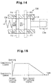
- Fig. 12 shows the roll angle of the forklift truck 1 when in a rolling state.
- the roll angle is detected by a rolling sensor (not shown) provided on the body frame 1a.
- the controller 31 outputs a locking signal based on the computed centrifugal force Fb. Accordingly, during successive turning of the forklift truck 1, the locking signal based on the altering rate ⁇ / ⁇ T is output even when the locking signal based on the computed centrifugal force Fb is not output when the steering angle ⁇ is close to zero degrees. Thus, when the forklift truck 1 turns right and then left successively, the rear axle 11 is constantly maintained in a locked state. This enables the forklift truck 1 to change directions in a stable manner.
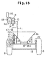
- Fig. 6 is an explanatory diagram that shows how a center of gravity G of the forklift truck 1 changes in accordance with the weight of the load carried on the forks 4 of the forklift truck 1.
- Diagonal lines have been drawn between the left front wheel 7 and the right rear wheel 8 and between the right front wheel 7 and the left rear wheel 8.
- the center of gravity when there is no load carried on the forks 4, is denoted as G1 and is located rearward with respect to the intersecting point X of the two diagonal lines.
- the weight of a load carried by the forks 4 causes the center of gravity G to move forward between the center of gravity G1 and the intersecting point X.
- the traction force of the rear wheels 8 increases, and the traction force of the front wheels 7 decreases.
- one of the front wheels 7 may be lifted from the ground. Accordingly, the controller 31 does not output the locking signal. This allows swinging of the rear axle 11. In this case, swinging of the rear axle 11 decreases the traction force of the rear wheels 8 and increases the traction force of the front wheels 7.
- the value of the hydraulic pressure y applied to the lifting cylinder 6 when the load on the forks 4 coincides the center of gravity G with the intersecting point X is set as the reference pressure value Nref.
- the center of gravity of the forklift truck 1 when the weight of the load carried by the forks 4 becomes equal to the maximum payload of the forklift truck 1, is denoted as G2 and is located in front of the intersecting point X.
- G2 The center of gravity of the forklift truck 1
- the traction force of the front wheels 7 increases.
- one of the rear wheels 8 may be lifted away from the ground.
- the rear axle 11 may be locked without interfering with the travel of the forklift truck 1.
- the forklift truck 1 is not equipped with the gyroscope and the acceleration sensor.
- An assumed yaw rate ⁇ x is obtained based on the steering angle ⁇ and the traveling speed v.
- the objective of this embodiment is to provide a structure that is capable of obtaining the same advantages of the first embodiment while having a decreased number of parts and a more cost-efficient structure.
- the controller 31 reads the traveling speed v at step 201 and the steering angle ⁇ at step 202.
- the controller 31 obtains the inverse of a turning radius r that is computed based on the steering angle ⁇ .
- the controller 31 computes an assumed centrifugal force Fx.
- the assumed centrifugal force Fx corresponds to the computed centrifugal force Fb of the first embodiment.
- the controller 31 obtains the assumed yaw rate altering rate ⁇ x1/ ⁇ T. The purpose of executing these steps are the same as the first embodiment and will not be described for the sake of brevity.
- the absolute value of the assumed centrifugal force Fx is compared with the maximum reference value Hmax in step 206 and the minimum reference value Hmin in step 208.
- the comparison is carried out with reference to a map illustrated in Fig. 10.
- the altering rate ⁇ x1/ ⁇ T is compared with the maximum reference value Kmax in step 210 and the minimum reference value Kmin in step 212.
- the purpose of executing these steps is the same as that of the first embodiment. After execution of steps 207, 211, 213, and 214, the controller 31 proceeds to step 115.
- the rear axle 11 is gradually released from the locked state be a hydraulic unit that operates the shock absorber 12 in a gradual manner.
- the interior of the shock absorber 12 is highly pressurized. If the pressure in the shock absorber 12 is suddenly decreased, the rear axle 11 may start to swing in a sudden manner.
- the operating mechanism of the shock absorber 12 employed in this embodiment regulates such undesirable swinging of the rear axle 11.
- an electromagnetic proportional valve 130 is employed in lieu of the electromagnetic switching valve 13.
- the controller 31 sends a duty signal to the proportional valve 130 by way of a driving circuit (not shown) to adjust the opening area of the proportional valve 130.
- the structure of the valve 130 will now be described.
- the proportional valve 130 includes a cylindrical body 14 and a spool 15, which is slidably accommodated in the body 14.
- the spool 15 is driven by an electromagnetic solenoid 13a and a spring 13b.
- the spool 15 is constantly urged toward an opening position by the spring 13b.
- a duty signal from the controller 31 excites the solenoid 13a, the spool 15 is moved to a closing position.
- the spool 15 is provided with a first groove F1 and a second groove F2.
- the first groove F1 When the spool 15 is at the opening position, the first groove F1 is aligned with the first and third holes E1, E3, and the second groove F2 is aligned with the second and fourth holes E2, E4.
- the first groove F1 connects the first oil passage P1 to the third oil passage P3
- the second groove F2 connects the second oil passage P2 to the fourth oil passage P4.
- the spool 15 is moved for a distance corresponding to the duty ratio of the duty signal sent from the controller 31.
- the movement of the spool 15 alters the aligned area between the first groove F1 and the corresponding holes E1, E3, and between the second groove F2 and the corresponding holes E2, E4.
- the movement of the spool 15 alters the opening area of the proportional valve 130. This adjusts the flow rate of the hydraulic oil flowing through the oil passages P1-P4.
- Hydraulic oil is supplied to the oil passages P1-P4 from the accumulator 16.
- the accumulator 16 also supplies oil to the lifting cylinder 6.
- the controller 31 locks the shock absorber 12 by means of the proportional valve 130 when any one of the conditions (a) to (f) for outputting the locking signal (described in the first embodiment) is satisfied. This, in turn, locks the rear axle 11.
- the controller 31 outputs the duty signal to the proportional valve 130 when none of the signal outputting conditions (a) to (f) is met.
- the duty ratio of the duty signal is one hundred percent.
- the duty ratio decreases gradually until it reaches zero percent.
- the opening area of the proportional valve is gradually increased. This gradually increases the amount of hydraulic oil that flows through the shock absorber 12. Accordingly, the rear axle 11 is gradually released from the locked state. Thus, sudden swinging of the rear axle 11 is prevented.
- the amount of hydraulic oil supplied to the lifting cylinder 6 is controlled by the proportional valve 130.
- Fig. 16 illustrates a further embodiment according to the present invention.
- This embodiment employs a first electromagnetic switching valve 41 that is similar to the one used in the first embodiment.
- a second electromagnetic switching valve 42 substitutes for the throttle valve 17.
- the second switching valve 42 has a minimal restricting passage 42a and a maximal restricting passage 42b, each of which restrict the flow of hydraulic oil. Hydraulic oil selectively flows through either the minimal restricting passage 42a or the maximal restricting passage 42b.
- the passage diameter of the minimal restricting passage 42a is greater than the passage diameter of the maximal restricting passage 42b.
- the controller 31 is connected to the second switching valve 42.
- the restricting area of the switching valve 42 is adjusted to gradually release the locked state of the rear axle 11.
- the minimal restricting passage 42a is selected to allow hydraulic oil flow therethrough.
- the shock absorber 12 supports the rear axle 11 in an unlocked state.
- the maximal restricting passage 42b is selected to allow hydraulic oil flow therethrough.
- the minimal restricting passage 42a is selected to allow hydraulic oil flow therethrough. This results in the shock absorber 12 releasing the locking of the rear axle 11.
- the flow rate of the hydraulic oil supplied to the shock absorber 12 is restricted by the minimal restricting passage 42a. This prevents sudden swinging of the rear axle 11 that may be caused by a sudden increase in the pressure within the shock absorber 12 and ensures stability of the traveling forklift truck 1.
- an electromagnetic proportional valve may substitute for the electromagnetic switching valve 42.
- Such a structure further prevents sudden swinging of the rear axle 11 when the controller 31 stops the output of the locking signal to have the shock absorber 12 release the rear axle from a locked state.
- a pair of coil springs B connect the rear axle 11 to the body frame 1a to absorb the impact transmitted to the frame 1 from the rear axle 11 when the axle 11 swings as the forklift truck 1 changes directions.
- the rear axle 11 is released from a locked state when the centrifugal force Fa detected by the acceleration sensor 21 becomes smaller a predetermined value.
- This structure is described in Japanese Unexamined Patent Publication No. 58-211903.
- the springs B absorb the impact that is transmitted to the entire vehicle as the vehicle is being steered to change directions, the centrifugal force applied to the vehicle may not be accurately detected. As a result, the locking of the rear axle 11 may be released even when the forklift truck 1 is changing directions. This embodiment solves this problem.
- an actual centrifugal force F swings the vehicle together with the rear axle 11.
- the force Fs of the spring B acts on the rear axle 11.
- the centrifugal force Fa detected by the acceleration sensor 21 corresponds to the resultant force of the actual centrifugal force F and the spring force Fs.
- the controller 31 compares the centrifugal force Fa with a predetermined maximum reference value Hmax and a predetermined minimum reference value Hmin. This comparison is carried out in the same manner as illustrated in the flowchart of Figs. 8(A), and 8(B). In this processing, the computed centrifugal force Fb replaces the centrifugal force Fa.
- the controller 31 stops the output of the locking signal when the predetermined time length Ta elapses after the centrifugal force Fa decreases from a value equal to or greater than the minimum reference value Hmin to a value smaller than the minimum reference value Hmin.
- Fig. 20 shows how the centrifugal force Fa detected by the acceleration sensor 21 changes as time elapses when the rear axle 11 is in a locked state during turning of the forklift truck 1.
- the value of the centrifugal force Fa is smaller than the minimum reference value Hmin due to the spring force Fs. Since the time period X1 is shorter than the predetermined time length Ta, the controller 31 continues to output a locking signal to the electromagnetic switching valve. After the vehicle stops turning, the centrifugal force Fa remains smaller than the minimum reference value Hmin during time period X2, which is longer than the predetermined time length Ta. Thus, the controller 31 stops the output of the locking signal when the predetermined time length Ta elapses. Accordingly, the rear axle 11 remains locked regardless of the centrifugal force Fa temporarily becoming smaller than the minimum reference value. This ensures stability of the forklift truck 1 when changing directions.
- a control apparatus for an industrial vehicle has a rear axle that is swingable upon a straight travel of the vehicle and fixed upon a turning of the vehicle.
- a damper locks or unlocks the rear axle.
- a controller has a memory that stores a first value and a second value of an angular velocity rate that represents an angular velocity per a unit time. The controller activates or deactivates the damper. The controller activates the damper to lock the rear axle when the angular velocity rate is greater than the first value. The controller deactivates the damper to unlock the rear axle when the angular velocity rate is kept smaller than the second value for a predetermined time period after the angular velocity rate has become smaller than the second value.
Landscapes
- Engineering & Computer Science (AREA)
- Mechanical Engineering (AREA)
- Transportation (AREA)
- Structural Engineering (AREA)
- Civil Engineering (AREA)
- Life Sciences & Earth Sciences (AREA)
- Geology (AREA)
- Vehicle Body Suspensions (AREA)
- Forklifts And Lifting Vehicles (AREA)
Applications Claiming Priority (27)
| Application Number | Priority Date | Filing Date | Title |
|---|---|---|---|
| JP63587/96 | 1996-03-19 | ||
| JP6358896 | 1996-03-19 | ||
| JP6358496 | 1996-03-19 | ||
| JP6358796 | 1996-03-19 | ||
| JP63584/96 | 1996-03-19 | ||
| JP6358896 | 1996-03-19 | ||
| JP63588/96 | 1996-03-19 | ||
| JP6358496 | 1996-03-19 | ||
| JP6358796 | 1996-03-19 | ||
| JP7480696 | 1996-03-28 | ||
| JP7480696 | 1996-03-28 | ||
| JP74806/96 | 1996-03-28 | ||
| JP8098772A JPH09286218A (ja) | 1996-04-19 | 1996-04-19 | 産業車両の制御装置 |
| JP98772/96 | 1996-04-19 | ||
| JP9877296 | 1996-04-19 | ||
| JP14956096 | 1996-06-11 | ||
| JP14956096 | 1996-06-11 | ||
| JP14955996 | 1996-06-11 | ||
| JP14955996A JP3166617B2 (ja) | 1996-03-28 | 1996-06-11 | 産業車両の制御装置 |
| JP14958196 | 1996-06-11 | ||
| JP14958296 | 1996-06-11 | ||
| JP149582/96 | 1996-06-11 | ||
| JP149559/96 | 1996-06-11 | ||
| JP149581/96 | 1996-06-11 | ||
| JP14958296A JP3159057B2 (ja) | 1996-03-19 | 1996-06-11 | 産業車両の制御装置 |
| JP14958196A JP3159056B2 (ja) | 1996-03-19 | 1996-06-11 | 産業車両の制御装置 |
| JP149560/96 | 1996-06-11 |
Publications (3)
| Publication Number | Publication Date |
|---|---|
| EP0796749A2 true EP0796749A2 (de) | 1997-09-24 |
| EP0796749A3 EP0796749A3 (de) | 1998-09-23 |
| EP0796749B1 EP0796749B1 (de) | 2001-10-17 |
Family
ID=27577107
Family Applications (1)
| Application Number | Title | Priority Date | Filing Date |
|---|---|---|---|
| EP97104599A Expired - Lifetime EP0796749B1 (de) | 1996-03-19 | 1997-03-18 | Nutzfahrzeug |
Country Status (5)
| Country | Link |
|---|---|
| US (1) | US6240353B1 (de) |
| EP (1) | EP0796749B1 (de) |
| KR (1) | KR100200187B1 (de) |
| CN (1) | CN1078857C (de) |
| DE (1) | DE69707330T2 (de) |
Cited By (14)
| Publication number | Priority date | Publication date | Assignee | Title |
|---|---|---|---|---|
| EP0908333A1 (de) * | 1997-10-06 | 1999-04-14 | Kabushiki Kaisha Toyoda Jidoshokki Seisakusho | Vorrichtung zur Regelung schwenkbarer Achsen in Nutzfahrzeugen |
| EP0909668A1 (de) * | 1997-10-15 | 1999-04-21 | Kabushiki Kaisha Toyoda Jidoshokki Seisakusho | Trägerstruktur für Fluiddruckzylinder zur Steuerung einer schwenkbaren Fahrzeugachse |
| EP0913279A2 (de) * | 1997-10-31 | 1999-05-06 | Kabushiki Kaisha Toyoda Jidoshokki Seisakusho | Einrichtung und Verfahren zur Beschränkung der Bewegung einer schwengbaren Achse eines Industriefahrzeuges |
| EP0913278A2 (de) * | 1997-10-30 | 1999-05-06 | Kabushiki Kaisha Toyoda Jidoshokki Seisakusho | Verfahren und Vorrichtung zur Begrenzung der Seitenneigung einer Achse für Industriefahrzeuge |
| EP0916527A2 (de) | 1997-11-13 | 1999-05-19 | Kabushiki Kaisha Toyoda Jidoshokki Seisakusho | Stabilitätsregelvorrichtung für Industriefahrzeuge |
| AU708494B2 (en) * | 1997-07-23 | 1999-08-05 | Kabushiki Kaisha Toyoda Jidoshokki Seisakusho | Axle pivoting controller and hydraulic cylinder for industrial vehicles |
| EP0965468A2 (de) * | 1998-06-17 | 1999-12-22 | Kabushiki Kaisha Toyoda Jidoshokki Seisakusho | Einbauposition für eine Dämpfungsvorrichtung in ein Nutzfahrzeug |
| EP0873893A3 (de) * | 1997-04-23 | 2000-07-26 | Kabushiki Kaisha Toyoda Jidoshokki Seisakusho | System zur Regelung der Aufbauneigung für Industriefahrzeuge |
| NL1012714C2 (nl) * | 1999-07-27 | 2001-01-30 | Bob Bakker | Stabilisatie-inrichting voor het zowel statisch als dynamisch stabiliseren van constructie-elementen. |
| US6396163B1 (en) | 1998-08-28 | 2002-05-28 | Kabushiki Kaisha Toyoda Jidoshokki Seisakusho | Mounting structure for sensor in industrial vehicle and industrial vehicle |
| CN1085972C (zh) * | 1997-12-02 | 2002-06-05 | 株式会社丰田自动织机制作所 | 用于工程车辆的车轴转动控制方法及装置 |
| EP1426205A2 (de) | 2002-12-04 | 2004-06-09 | Jungheinrich Aktiengesellschaft | Vierradflurförderzeug mit Pendelachse |
| EP0916526A3 (de) * | 1997-11-14 | 2004-06-30 | Kabushiki Kaisha Toyota Jidoshokki | Einrichtung zur Steuerung der Neigung einer Achse eines Industriefahrzeuges |
| DE102016210006A1 (de) | 2016-06-07 | 2017-12-07 | Jungheinrich Aktiengesellschaft | Integrierte Lenkachse mit einstellbarer Dämpfung |
Families Citing this family (15)
| Publication number | Priority date | Publication date | Assignee | Title |
|---|---|---|---|---|
| KR100481447B1 (ko) * | 1997-07-28 | 2005-07-28 | 대우종합기계 주식회사 | 전동지게차의 유압모터 회전속도 조절장치 |
| US6829835B2 (en) * | 2002-11-21 | 2004-12-14 | Martin Pfeil Trawid-Gmbh | Lifting vehicle |
| DE10305671A1 (de) * | 2003-02-12 | 2004-08-26 | Jungheinrich Aktiengesellschaft | Verfahren zum Betrieb eines Staplers |
| GB2412902B (en) * | 2004-04-07 | 2008-04-09 | Linde Ag | Industrial truck having increased static or quasi-static tipping stability |
| JP4615899B2 (ja) * | 2004-06-07 | 2011-01-19 | 日産自動車株式会社 | 車両用旋回走行制御装置 |
| US20070239312A1 (en) * | 2006-04-10 | 2007-10-11 | Andersen Scott P | System and method for tracking inventory movement using a material handling device |
| EP3255239A1 (de) * | 2010-04-16 | 2017-12-13 | BAUER Maschinen GmbH | Baumaschine mit rechnereinheit zum ermitteln eines verstellbereichs |
| DE102010048662A1 (de) * | 2010-10-07 | 2012-04-12 | Jungheinrich Aktiengesellschaft | Flurförderzeug mit einem höhenverstellbaren Lasttragmittel |
| BR112013020758A2 (pt) | 2011-02-16 | 2016-10-18 | Crown Equip Corp | veículo de manipulação de materiais |
| JP5725990B2 (ja) * | 2011-06-14 | 2015-05-27 | 住友ナコ マテリアル ハンドリング株式会社 | リーチ式フォークリフトおよびサスペンション機構 |
| US8909437B2 (en) * | 2012-10-17 | 2014-12-09 | Caterpillar Inc. | Payload Estimation system |
| CN104709853B (zh) * | 2015-03-23 | 2017-03-15 | 杭叉集团股份有限公司 | 伸缩臂叉车侧平动作保护系统 |
| CN104925701B (zh) * | 2015-06-19 | 2017-07-18 | 合肥工业大学 | 叉车横向稳定性控制方法及其电控系统 |
| JP6612210B2 (ja) * | 2016-12-26 | 2019-11-27 | 本田技研工業株式会社 | 作業機 |
| CN112147935B (zh) * | 2020-09-25 | 2022-04-08 | 劢微机器人科技(深圳)有限公司 | 无人叉车叉臂控制方法、装置、设备及存储介质 |
Family Cites Families (25)
| Publication number | Priority date | Publication date | Assignee | Title |
|---|---|---|---|---|
| JPS4977619A (de) | 1972-11-29 | 1974-07-26 | ||
| JPS508220A (de) | 1973-05-29 | 1975-01-28 | ||
| US4393959A (en) * | 1980-12-10 | 1983-07-19 | Allis-Chalmers Corporation | Hydraulic stabilizer for axle on mast lift vehicle |
| JPS57109007A (en) | 1980-12-26 | 1982-07-07 | Fujitsu Ltd | Correction system for machine control data |
| US4511974A (en) * | 1981-02-04 | 1985-04-16 | Kabushiki Kaisha Toyoda Jidoshokki Seisakusho | Load condition indicating method and apparatus for forklift truck |
| JPS58167215A (ja) * | 1982-03-27 | 1983-10-03 | Toyoda Autom Loom Works Ltd | 産業車両における車軸固定装置 |
| JPS58167214A (ja) | 1982-03-27 | 1983-10-03 | Toyoda Autom Loom Works Ltd | 産業車両における車軸固定装置 |
| JPS58167400A (ja) | 1982-03-27 | 1983-10-03 | 株式会社豊田自動織機製作所 | フオ−クリフトトラツクにおける車軸固定装置 |
| JPS58211903A (ja) * | 1982-06-02 | 1983-12-09 | Toyoda Autom Loom Works Ltd | 産業車両における車軸固定装置 |
| JPS58214406A (ja) | 1982-06-05 | 1983-12-13 | Toyoda Autom Loom Works Ltd | 産業車両における車軸固定装置 |
| JPS6239386A (ja) | 1985-08-15 | 1987-02-20 | スズキ株式会社 | 自動二輪車の可変サスペンシヨン装置 |
| JP2509298B2 (ja) * | 1988-06-10 | 1996-06-19 | 日産自動車株式会社 | 能動型サスペンション及び横加速度センサの配設位置決定方法 |
| JP3179079B2 (ja) | 1989-06-22 | 2001-06-25 | 富士重工業株式会社 | 車両用アクテイブサスペンションの制御方法 |
| JP2611449B2 (ja) | 1989-08-31 | 1997-05-21 | 日産自動車株式会社 | 能動型サスペンション |
| JPH03136915A (ja) * | 1989-10-24 | 1991-06-11 | Matsushita Electric Ind Co Ltd | サスペンション制御装置 |
| JPH05193322A (ja) | 1992-01-14 | 1993-08-03 | Nippondenso Co Ltd | 車両のサスペンション制御装置 |
| JP2579202Y2 (ja) * | 1992-04-10 | 1998-08-20 | 株式会社小松製作所 | 圧力補償弁を備えた操作弁 |
| JP3194451B2 (ja) | 1993-02-24 | 2001-07-30 | 株式会社ユニシアジェックス | 車両懸架装置 |
| JPH0732848A (ja) | 1993-07-22 | 1995-02-03 | Hitachi Constr Mach Co Ltd | サスペンションの油圧制御装置 |
| DE4420682A1 (de) * | 1994-06-14 | 1996-01-04 | Rexroth Mannesmann Gmbh | Hydrauliksteuerung für eine teilende Werkzeugmaschine |
| JP2892939B2 (ja) * | 1994-06-28 | 1999-05-17 | 日立建機株式会社 | 油圧掘削機の油圧回路装置 |
| DE19500747C2 (de) * | 1995-01-12 | 2000-03-09 | Danfoss As | Zwei-Wege-Sitzventil |
| JPH08233138A (ja) * | 1995-02-27 | 1996-09-10 | Konan Denki Kk | リリーフ弁 |
| JP3369033B2 (ja) * | 1995-08-31 | 2003-01-20 | アルプス電気株式会社 | 振動型ジャイロスコープ |
| US5921279A (en) * | 1998-04-29 | 1999-07-13 | Husco International, Inc. | Solenoid operated dual spool control valve |
-
1997
- 1997-03-18 DE DE69707330T patent/DE69707330T2/de not_active Expired - Lifetime
- 1997-03-18 KR KR1019970009733A patent/KR100200187B1/ko not_active IP Right Cessation
- 1997-03-18 US US08/828,180 patent/US6240353B1/en not_active Expired - Lifetime
- 1997-03-18 EP EP97104599A patent/EP0796749B1/de not_active Expired - Lifetime
- 1997-03-18 CN CN97109674A patent/CN1078857C/zh not_active Expired - Lifetime
Non-Patent Citations (1)
| Title |
|---|
| SHIBI F.: "FORSCHUNG - FB NR.395", 1985, BUNDESANSTALT FÜR ARBEITSSCHUTZ, DORTMUND, DE, ISBN: 3-88314-385-5, article "Untersuchung zur Erhöhung der Kippstabilität von Gabelstaplern", pages: 130, XP000945407 |
Cited By (27)
| Publication number | Priority date | Publication date | Assignee | Title |
|---|---|---|---|---|
| US6266594B1 (en) | 1997-04-23 | 2001-07-24 | Kabushiki Kaisha Toyoda Jidoshokki Seisakusho | Body swing control apparatus for industrial vehicles |
| EP0873893A3 (de) * | 1997-04-23 | 2000-07-26 | Kabushiki Kaisha Toyoda Jidoshokki Seisakusho | System zur Regelung der Aufbauneigung für Industriefahrzeuge |
| AU708494B2 (en) * | 1997-07-23 | 1999-08-05 | Kabushiki Kaisha Toyoda Jidoshokki Seisakusho | Axle pivoting controller and hydraulic cylinder for industrial vehicles |
| EP0908333A1 (de) * | 1997-10-06 | 1999-04-14 | Kabushiki Kaisha Toyoda Jidoshokki Seisakusho | Vorrichtung zur Regelung schwenkbarer Achsen in Nutzfahrzeugen |
| US6290245B1 (en) | 1997-10-06 | 2001-09-18 | Kabushiki Kaisha Toyoda Jidoshokki Seisakusho | Apparatus for controlling pivoting of axles in industrial vehicles |
| CN1105041C (zh) * | 1997-10-15 | 2003-04-09 | 株式会社丰田自动织机制作所 | 控制车轴旋转用液压缸的支撑机构 |
| KR100348506B1 (ko) * | 1997-10-15 | 2002-10-25 | 가부시키가이샤 도요다 지도숏키 | 차축의요동제어용유압실린더의지지구조체 |
| EP0909668A1 (de) * | 1997-10-15 | 1999-04-21 | Kabushiki Kaisha Toyoda Jidoshokki Seisakusho | Trägerstruktur für Fluiddruckzylinder zur Steuerung einer schwenkbaren Fahrzeugachse |
| EP0913278A3 (de) * | 1997-10-30 | 2001-04-04 | Kabushiki Kaisha Toyoda Jidoshokki Seisakusho | Verfahren und Vorrichtung zur Begrenzung der Seitenneigung einer Achse für Industriefahrzeuge |
| EP0913278A2 (de) * | 1997-10-30 | 1999-05-06 | Kabushiki Kaisha Toyoda Jidoshokki Seisakusho | Verfahren und Vorrichtung zur Begrenzung der Seitenneigung einer Achse für Industriefahrzeuge |
| EP0913279A3 (de) * | 1997-10-31 | 2004-05-06 | Kabushiki Kaisha Toyota Jidoshokki | Einrichtung und Verfahren zur Beschränkung der Bewegung einer schwengbaren Achse eines Industriefahrzeuges |
| EP0913279A2 (de) * | 1997-10-31 | 1999-05-06 | Kabushiki Kaisha Toyoda Jidoshokki Seisakusho | Einrichtung und Verfahren zur Beschränkung der Bewegung einer schwengbaren Achse eines Industriefahrzeuges |
| EP0916527A2 (de) | 1997-11-13 | 1999-05-19 | Kabushiki Kaisha Toyoda Jidoshokki Seisakusho | Stabilitätsregelvorrichtung für Industriefahrzeuge |
| EP0916527A3 (de) * | 1997-11-13 | 2005-02-09 | Kabushiki Kaisha Toyota Jidoshokki | Stabilitätsregelvorrichtung für Industriefahrzeuge |
| EP0916526A3 (de) * | 1997-11-14 | 2004-06-30 | Kabushiki Kaisha Toyota Jidoshokki | Einrichtung zur Steuerung der Neigung einer Achse eines Industriefahrzeuges |
| CN1085972C (zh) * | 1997-12-02 | 2002-06-05 | 株式会社丰田自动织机制作所 | 用于工程车辆的车轴转动控制方法及装置 |
| EP0921021A3 (de) * | 1997-12-02 | 2005-02-09 | Kabushiki Kaisha Toyota Jidoshokki | Verfahren und Vorrichtung zur Steuerung einer schwenkbaren Achse für Nutzfahrzeuge |
| US6398242B1 (en) | 1998-06-17 | 2002-06-04 | Kabushiki Kaisha Toyoda Jidoshokki Seisakusho | Installation position of a damper for industrial vehicles |
| EP0965468A3 (de) * | 1998-06-17 | 2001-03-28 | Kabushiki Kaisha Toyoda Jidoshokki Seisakusho | Einbauposition für eine Dämpfungsvorrichtung in ein Nutzfahrzeug |
| EP0965468A2 (de) * | 1998-06-17 | 1999-12-22 | Kabushiki Kaisha Toyoda Jidoshokki Seisakusho | Einbauposition für eine Dämpfungsvorrichtung in ein Nutzfahrzeug |
| US6396163B1 (en) | 1998-08-28 | 2002-05-28 | Kabushiki Kaisha Toyoda Jidoshokki Seisakusho | Mounting structure for sensor in industrial vehicle and industrial vehicle |
| WO2001007275A1 (en) * | 1999-07-27 | 2001-02-01 | Stabilex | Stability arrangement for moving structural components |
| NL1012714C2 (nl) * | 1999-07-27 | 2001-01-30 | Bob Bakker | Stabilisatie-inrichting voor het zowel statisch als dynamisch stabiliseren van constructie-elementen. |
| EP1426205A2 (de) | 2002-12-04 | 2004-06-09 | Jungheinrich Aktiengesellschaft | Vierradflurförderzeug mit Pendelachse |
| DE10256539B4 (de) * | 2002-12-04 | 2006-02-16 | Jungheinrich Ag | Vierradflurförderzeug mit Pendelachse |
| US7137473B2 (en) | 2002-12-04 | 2006-11-21 | Jungheinrich Aktiengesellschaft | Four-wheel industrial truck with a swing axle |
| DE102016210006A1 (de) | 2016-06-07 | 2017-12-07 | Jungheinrich Aktiengesellschaft | Integrierte Lenkachse mit einstellbarer Dämpfung |
Also Published As
| Publication number | Publication date |
|---|---|
| CN1171337A (zh) | 1998-01-28 |
| DE69707330T2 (de) | 2002-06-27 |
| US6240353B1 (en) | 2001-05-29 |
| CN1078857C (zh) | 2002-02-06 |
| KR100200187B1 (ko) | 1999-06-15 |
| DE69707330D1 (de) | 2001-11-22 |
| EP0796749B1 (de) | 2001-10-17 |
| KR970065402A (ko) | 1997-10-13 |
| EP0796749A3 (de) | 1998-09-23 |
Similar Documents
| Publication | Publication Date | Title |
|---|---|---|
| EP0796749B1 (de) | Nutzfahrzeug | |
| EP0884202B1 (de) | Vorrichtung und Verfahren zur Regelung der Neigung einer Achse für Industriefahrzeuge | |
| US6175796B1 (en) | Apparatus and method for restricting pivoting of industrial vehicles axles | |
| AU710595B2 (en) | Axle pivot control method and apparatus for industrial vehicle | |
| US6719098B1 (en) | Stability control apparatus for industrial vehicles | |
| US4901811A (en) | Vehicle steering system for adjusting tire characteristic | |
| EP0315457B1 (de) | Vorrichtung und Verfahren zur Regelung einer Fahrzeugaufhängung | |
| JP3166617B2 (ja) | 産業車両の制御装置 | |
| EP0908333B1 (de) | Vorrichtung zur Regelung schwenkbarer Achsen in Nutzfahrzeugen | |
| EP0913278A2 (de) | Verfahren und Vorrichtung zur Begrenzung der Seitenneigung einer Achse für Industriefahrzeuge | |
| JP3159057B2 (ja) | 産業車両の制御装置 | |
| JP3159056B2 (ja) | 産業車両の制御装置 | |
| KR100366470B1 (ko) | 산업차량용차축요동제어기및유압실린더 | |
| JPH05178060A (ja) | 輪荷重移動制御装置 | |
| JPH0541443B2 (de) | ||
| JP3164005B2 (ja) | 産業車両の車体揺動制御装置 | |
| KR0142383B1 (ko) | 차량용 능동 롤 제어장치 | |
| JPH09286218A (ja) | 産業車両の制御装置 | |
| JPH10287116A (ja) | 産業車両の揺動制御装置 |
Legal Events
| Date | Code | Title | Description |
|---|---|---|---|
| PUAI | Public reference made under article 153(3) epc to a published international application that has entered the european phase |
Free format text: ORIGINAL CODE: 0009012 |
|
| 17P | Request for examination filed |
Effective date: 19970318 |
|
| AK | Designated contracting states |
Kind code of ref document: A2 Designated state(s): DE FR GB |
|
| PUAL | Search report despatched |
Free format text: ORIGINAL CODE: 0009013 |
|
| AK | Designated contracting states |
Kind code of ref document: A3 Designated state(s): DE FR GB |
|
| TPAD | Observations filed by third parties |
Free format text: ORIGINAL CODE: EPIDOS TIPA |
|
| GRAG | Despatch of communication of intention to grant |
Free format text: ORIGINAL CODE: EPIDOS AGRA |
|
| 17Q | First examination report despatched |
Effective date: 20010205 |
|
| GRAG | Despatch of communication of intention to grant |
Free format text: ORIGINAL CODE: EPIDOS AGRA |
|
| GRAH | Despatch of communication of intention to grant a patent |
Free format text: ORIGINAL CODE: EPIDOS IGRA |
|
| GRAH | Despatch of communication of intention to grant a patent |
Free format text: ORIGINAL CODE: EPIDOS IGRA |
|
| GRAA | (expected) grant |
Free format text: ORIGINAL CODE: 0009210 |
|
| AK | Designated contracting states |
Kind code of ref document: B1 Designated state(s): DE FR GB |
|
| REF | Corresponds to: |
Ref document number: 69707330 Country of ref document: DE Date of ref document: 20011122 |
|
| RAP2 | Party data changed (patent owner data changed or rights of a patent transferred) |
Owner name: KABUSHIKI KAISHA TOYOTA JIDOSHOKKI |
|
| REG | Reference to a national code |
Ref country code: GB Ref legal event code: IF02 |
|
| ET | Fr: translation filed | ||
| PLBE | No opposition filed within time limit |
Free format text: ORIGINAL CODE: 0009261 |
|
| STAA | Information on the status of an ep patent application or granted ep patent |
Free format text: STATUS: NO OPPOSITION FILED WITHIN TIME LIMIT |
|
| 26N | No opposition filed | ||
| REG | Reference to a national code |
Ref country code: FR Ref legal event code: PLFP Year of fee payment: 20 |
|
| PGFP | Annual fee paid to national office [announced via postgrant information from national office to epo] |
Ref country code: DE Payment date: 20160315 Year of fee payment: 20 |
|
| PGFP | Annual fee paid to national office [announced via postgrant information from national office to epo] |
Ref country code: FR Payment date: 20160208 Year of fee payment: 20 Ref country code: GB Payment date: 20160316 Year of fee payment: 20 |
|
| REG | Reference to a national code |
Ref country code: DE Ref legal event code: R071 Ref document number: 69707330 Country of ref document: DE |
|
| REG | Reference to a national code |
Ref country code: GB Ref legal event code: PE20 Expiry date: 20170317 |
|
| PG25 | Lapsed in a contracting state [announced via postgrant information from national office to epo] |
Ref country code: GB Free format text: LAPSE BECAUSE OF EXPIRATION OF PROTECTION Effective date: 20170317 |