EP0776105B1 - Cdma-demodulator - Google Patents
Cdma-demodulator Download PDFInfo
- Publication number
- EP0776105B1 EP0776105B1 EP96917644A EP96917644A EP0776105B1 EP 0776105 B1 EP0776105 B1 EP 0776105B1 EP 96917644 A EP96917644 A EP 96917644A EP 96917644 A EP96917644 A EP 96917644A EP 0776105 B1 EP0776105 B1 EP 0776105B1
- Authority
- EP
- European Patent Office
- Prior art keywords
- interference
- signal
- channel variation
- reception
- path
- Prior art date
- Legal status (The legal status is an assumption and is not a legal conclusion. Google has not performed a legal analysis and makes no representation as to the accuracy of the status listed.)
- Expired - Lifetime
Links
Images


Classifications
-
- H—ELECTRICITY
- H04—ELECTRIC COMMUNICATION TECHNIQUE
- H04B—TRANSMISSION
- H04B1/00—Details of transmission systems, not covered by a single one of groups H04B3/00 - H04B13/00; Details of transmission systems not characterised by the medium used for transmission
- H04B1/69—Spread spectrum techniques
- H04B1/707—Spread spectrum techniques using direct sequence modulation
- H04B1/709—Correlator structure
-
- H—ELECTRICITY
- H04—ELECTRIC COMMUNICATION TECHNIQUE
- H04B—TRANSMISSION
- H04B1/00—Details of transmission systems, not covered by a single one of groups H04B3/00 - H04B13/00; Details of transmission systems not characterised by the medium used for transmission
- H04B1/69—Spread spectrum techniques
- H04B1/707—Spread spectrum techniques using direct sequence modulation
- H04B1/7097—Interference-related aspects
- H04B1/7103—Interference-related aspects the interference being multiple access interference
- H04B1/7107—Subtractive interference cancellation
- H04B1/71075—Parallel interference cancellation
-
- H—ELECTRICITY
- H04—ELECTRIC COMMUNICATION TECHNIQUE
- H04B—TRANSMISSION
- H04B1/00—Details of transmission systems, not covered by a single one of groups H04B3/00 - H04B13/00; Details of transmission systems not characterised by the medium used for transmission
- H04B1/69—Spread spectrum techniques
- H04B1/707—Spread spectrum techniques using direct sequence modulation
- H04B1/7097—Interference-related aspects
- H04B1/7103—Interference-related aspects the interference being multiple access interference
- H04B1/7107—Subtractive interference cancellation
- H04B2001/71077—Partial interference cancellation
-
- H—ELECTRICITY
- H04—ELECTRIC COMMUNICATION TECHNIQUE
- H04W—WIRELESS COMMUNICATION NETWORKS
- H04W52/00—Power management, e.g. TPC [Transmission Power Control], power saving or power classes
- H04W52/04—TPC
- H04W52/06—TPC algorithms
- H04W52/12—Outer and inner loops
Definitions
- the present invention relates to a code division multiple access (CDMA) demodulating apparatus used for receiving signals of a CDMA system using spread spectrum, and more specifically to a CDMA demodulating apparatus suitable for a mobile communication system which uses a cellular configuration.
- CDMA code division multiple access
- DS (Direct Sequence) - CDMA is a system in which a plurality of users carry out communications using a same frequency band, and each user is identified by a spreading code.
- a spreading code for each user a spreading code such as Gold code is used.
- Interference signal power of another user is a reciprocal of average spreading factor (PG) in the despreading process of a receiver.
- PG average spreading factor
- SIR Signal-to-Interference Ratio
- SIR is a ratio of the reception signal power at the user of the desired wave to the interference signal power received from another user.
- SIR is a ratio of the reception signal power at the user of the desired wave to the interference signal power received from another user.
- the transmission power control is perfect, and the SIR in the base station receiver input is maintained at a constant value, under multipath environment of mobile communications, spreading codes will never quadrate completely with each other. Therefore, the user is subject to interference due to cross-correlation of the power of a reciprocal of spreading factor at an average per one of other users.
- the multi-user type interference canceler not only demodulates a desired wave signal of its own channel, but also demodulates a signal of another user using spreading code information and reception signal timing of the other user.
- the single user type interference canceler uses only the spreading code of own channel to minimize an average cross-correlation and noise component from the other user.
- the multi-user type canceler includes a linear processing type (decorrelator or the like) and a nonlinear processing type.
- the decorrelator calculates mutual correlation of the spreading code of own channel and all other spreading codes of receiver input to determine an inverse matrix composed of the cross-correlation, and the cross-correlation is canceled by compensating for the output signal of a matched filter using this inverse matrix.
- K is a number of users
- Lk is a number of reception paths to individual users
- dimension Dm of the decorrelator matrix is given by the following equation.
- a nonlinear multi-user type interference canceler is a replica reproduction type interference canceler. This canceler demodulates interference signal from other user's channel, decides it to reproduce transmission information data replica, calculates an interference signal replica of each channel from this replica, and subtracts the interference replica from the reception signal, thereby demodulating the desired wave signal with enhanced SIR.
- Fig. 1 shows a replica reproduction type multi-stage interference canceler (serial interference canceler) proposed in the document "Serial interference cancellation method for CDMA", IEE, Electronics Letters Vol. 30, No. 19, pp. 1581-1582, Sept. 1994.
- the numeral 11 indicates a spread signal
- 12, 16 are delay units
- 13, 17 are matched filters
- 14, 18 are respreaders
- 15 is a interference subtractor.
- the serial canceler comprises interference canceling blocks in a plurality of stages, connected in series, whereby the interference canceling blocks of individual stages carry out demodulation and generation of interference signal replica by turns to M users to be demodulated.
- the receiver first rearranges the reception signals in the order of reception signal level. For explanation, serial numbers from 1 to M are assigned to the rearranged signals, number 1 being assigned to the highest reception signal level.
- the interference canceling block of the first stage makes despreading, demodulation and data decision by the matched filter 13 on the reception signal of number 1, and the resulting reproduction data is referred to as D 1 (1) .
- the respreader 14 calculates an interference signal replica S 1 (1) of this channel from the reproduction data D 1 (1) .
- the interference subtractor 15 subtracts the interference signal replica from a reception signal S passed through the delay unit 16.
- the matched filter 17 makes despreading, demodulation and data decision on the signal obtained by the subtraction using the spreading code replica of user 2 to obtain a reproduction data D 2 (1) of user 2.
- the matched filter input signal of user 2 is improved in SIR to the extent that the interference signal replica S 1 (1) of user 1 is subtracted as compared with direct despreading from the reception signal S.
- an interference signal replica S 2 (1) is obtained from the reproduction data.
- a matched filter input signal of user 3 is obtained by subtracting interference signal replicas of users 1 and 2 from the reception signal S passed through the delay unit. Using this procedure, for subsequent users, the reception SIR can be further enhanced.
- interference signal replicas S 1 (1) + S 2 (1) + ....S M-1 (1) of a total of (M-1) users are subtracted from the reception signal S to produce a signal, thereby considerably improving the SIR over the reception signal S. As a result, demodulated signal of M'th channel is improved in reliability.
- interference signal replicas S 1 (1) , S 2 (1) , . ., S M-1 (1) of individual users estimated in the first stage interference canceling block Similar despreading, demodulation, data decision, and respreading are carried out in the second stage interference canceling block.
- interference signal replicas S 2 (1) + S 3 (1) + . + S M (1) other than of user 1 determined by the first stage interference canceling block are subtracted from the reception signal S to produce a signal of improved SIR, and on this signal, despreading, demodulation and data decision are carried out.
- Similar processing is applied.
- a signal obtained by subtracting interference signal replicas in the first stage of channels other than own channel from the reception signal S, is subjected to respreading, demodulation, and data decision, and from the reproduction data, interference signal replicas S 1 (2) , S 2 (2) , . , S M (2) of individual channels in the second stage interference canceling block are determined.
- amplitude variation and phase variation occur due to Rayleigh fading in association with variation in relative positions between the mobile station and base station.
- the multi-stage type interference canceler serial interference canceler shown in Fig. 1
- the channel (phase; amplitude) estimation accuracy greatly affects the reception characteristics of the multi-stage type interference canceler, but realizability thereof is not described in the above document.
- Figs. 2A and 2B are block diagrams showing a serial canceler shown in this document.
- Fig. 3 shows the channel structure of the method.
- the numeral 21 indicates a spreading code input terminal
- 22 is a first stage reproduction data output terminal of user 1
- 23 is a delay unit
- 24 is a pilot channel transmission path variation estimator
- 25 is an interference subtractor
- 26 is a first stage interference canceling block
- 27 is a second stage interference canceling block
- 28 is a matched filter
- 29 is a transmission path compensator
- 30 is a RAKE combiner
- 31 is data decision block
- 32 is a signal distributor
- 33 is a transmission path variation adder
- 34 is a respreader.
- This system is provided with a pilot channel having a known transmission pattern parallel with the communication channel. Transmission path estimation is made based on the reception phase of the pilot channel. Further, amplitude/phase estimation of the reception signal of each path of each user is carried out based on the transmission path estimation of the pilot channel. Still further, using the amplitude/phase estimation value, interference canceling of several stages is carried out by the serial interference canceling block to reproduce data of each user. In this case, as in the previous document, individual paths are ranked in the decreasing order of the sum of reception signal power. In the case of Figs. 2A and 2B, the user 1 reception signal power is assumed as to be the highest.
- each path of user 1 is despread by a matched filter 28, in a transmission path variation compensator 29, each path of user 1 is compensated for phase variation according to the phase variation of each path estimated with respect to the pilot channel.
- signals of the phase variation compensated paths are phase synthesized by a reception complex envelope curve of individual paths.
- the phase synthesized signal is decided by the data decision block 31 to obtain reproduction data of user 1.
- the distributor 32 distributes the reproduction data replica according to weighting at the RAKE combining, the transmission path variation adder 33 gives a phase variation of each path, and the respreader 34 makes respreading by spreading code of each path to produce the interference signal replica S 1 (1) .
- a delay unit 35 delays the reception signal S.
- the interference subtractor 25 subtracts the interference signal replica S 1 (1) of user 1 from the delayed signal.
- the first stage interference canceling block of user 2 carries out despreading. phase compensation, RAKE combining, data decision, and production of interference signal replica for each path to the output signal of the interference subtractor 25.
- the input signal of the interference signal canceling block of user 2 is improved in reception SIR to the extent that the user 1 interference signal replicas are subtracted.
- reproduction data is estimated for each user by the first stage interference canceling block up to user M to obtain interference signal replicas.
- the interference signal canceling block of second stage carries out similar processing using interference signal replicas S 1 (1) , S 2 (1) , ..., S M (1) obtained by the interference signal canceling block of the first stage.
- the second stage interference signal canceling block 27 (comprising the components 28-34 of the first stage) of user 1 makes data demodulation by despreading the signal obtained by subtracting the channel interference signal replicas other than own channel from the reception signal S delayed by delay unit 23.
- a difference of the prior art method from the method described in the previous document is the following point.
- interference signal replicas S 1 (1) + S 3 (1) + ... +S M (1) in the foregoing stage are used as interference signal replicas of all paths.
- S 1 (2) is used as an interference signal replica of user 1 in the second stage.
- the estimated value S 1 (2) in this stage is higher in reliability. Therefore, the accuracy of the desired wave signal obtained by subtracting the interference replicas. and reliability of decision data obtained by demodulation are also improved.
- a pilot channel is provided in parallel with the communication channel for each user, and a channel estimated in the pilot channel is used in each stage of interference canceling block.
- channel estimation in the pilot channel is carried out independent of the interference canceling loop, to estimate channel (phase, amplitude) variation in high accuracy, it has been necessary to make averaging over a very long time (using many pilot symbols).
- channel estimation values in this period be approximately constant, therefore, it is limited to be applied to an environment of fast channel variation (high fading frequency).
- fading fast
- averaging is possible only in a range where the values can be regarded as constant, it is therefore impossible to obtain a sufficient channel estimation accuracy if the number of averaging symbols is small.
- An object of the present invention is to provide a CDMA demodulating apparatus, which can improve reliability of reproduction data in a low SIR environment with a number of simultaneous users.
- a CDMA demodulating apparatus for use in a CDMA communication system that performs spreading of the information data by a spreading code faster than the information rate to a wideband signal, the wideband signal being transmitted to achieve multiple access transmission, wherein a pilot symbol of known pattern is received to estimate channel variation, individual reception signals received through a plurality of channels are compensated by the estimated channel variation, and the compensated reception signal is demodulated to reproduce the information data
- the CDMA demodulating apparatus comprising:
- a CDMA demodulating apparatus for use in a CDMA system that performs multiple access transmission by transmitting a spread signal, the spread signal being generated by spreading information data into a wideband signal with a spreading code whose rate is higher than an information rate, wherein a pilot symbol of a known pattern to estimate a channel variation, each reception signal received through a plurality of channels is compensated by the estimated channel variation, and the compensated reception signal is demodulated to reproduce the information data
- the demodulating apparatus comprising:
- channel variation is estimated using a pilot signal in each channel of each stage.
- a channel variation estimator using the pilot signal is included in the interference canceler loop of each channel of each stage.
- interference is removed by a decorrelation filter to improve the SIR, and then demodulation is made, thereby improving the accuracy of decision data and interference signal replica. Since subsequent interference cancelers perform interference canceling using the decision data and interference signal replicas, estimation accuracy of channel variation is improved.
- interference reduction is made using a decorrelator, and channel estimation is carried out on the interference reduced signal using a pilot symbol, thereby improving the estimation accuracy on the several users.
- the communication quality is measured at the output side of the multi-user type interference canceler, the reception quality information is fed back to the SIR threshold value of SIR measurement, and a constant SIR type closed loop transmission power control is performed by the matched filter output signal, thereby achieving transmission power control signal based on SIR of interference reduced signal without increasing delay of control.
- Fig. 4 is a block diagram showing the entire construction of the first embodiment of the CDMA demodulating apparatus according to the present invention
- Figs. 5A and 5B are block diagrams showing the construction of interference canceling blocks of the first stage and the second stage of the CDMA demodulating apparatus
- Fig. 6 is a schematic view showing the frame arrangement of the CDMA demodulating apparatus to which the present invention is applied.
- the frame of the system to which the present invention is applied has a structure in which pilot signals of a known pattern are inserted periodically between information signals in units of several symbols.
- a receiver of the system comprises, as shown in Fig. 4, matched filters 103 and received level detectors 104 provided corresponding to channels 1-N, a channel ranking unit 105, and interference canceling blocks 106-108 of first-H' th stages.
- the matched filter 103 in each path of each channel, performs correlation detection of the spreading code replica with the reception signal using the spreading code in phase with the reception timing as a spreading code replica.
- the received level detector 104 makes a sum of reception power of individual paths outputted from the matched filters 103 to detect the received level of a desired wave.
- the channel ranking unit 105 outputs a channel ranking information for controlling the order of demodulation of users of the receiver input according to the reception signal level of each user.
- the interference canceling blocks 106-108 perform demodulation in the order of higher received level according to the channel ranking information, and output new interference signal replicas of individual users using interference signal replicas estimated by the interference canceling block of the previous stage.
- Figs. 5A and 5B individually show the constructions of the interference canceling blocks 106 and 107.
- a received spread signal S supplied to an input end 201 of the interference canceling block 106 is fed to delay units 202, 203 (203-2 - 203-M) and an interference canceling unit 210-1(hereinafter referred to as ICU).
- Output of the delay unit 202 is fed to the interference canceling block 107 of the second stage.
- output of each delay unit 203 is fed to each interference subtractor 204 (204-2 - 204-M).
- These delay units 203 are for synchronizing processing timing.
- the ICU are provided in the number of users x number of stages.
- the structure is illustrated using the ICU 210-1 of user 1 of the first stage as an example.
- the ICU 210-1 comprises a matched filter 211, a pilot symbol channel variation estimator (herein after referred to as PCHE) 212 and a channel variation compensator 213, a RAKE combiner 214, and a data decision block 215 provided in each of multiple paths, a channel variation adding unit 216 and a respreader 217 provided in each path, and an adder 218, and output of the adder 218 (channel variation estimation value) is outputted from an output terminal 219.
- PCHE pilot symbol channel variation estimator
- the matched filter 211 makes cross-correlation of a received spread signal with a spreading code for each path, and outputs a despread signal.
- the PCHE 212 estimates a variation in the transmission path of each path of each symbol in the despread signal. That is, for each path, the transmission variation estimated by the pilot symbol is interpolated into the information position in the section to estimate the transmission path variation in each information symbol.
- the channel variation compensator 213 compensate an estimated phase variation for each path.
- the RAKE combiner 214 makes weighted combination of output signal of each channel variation compensator 213 according to the magnitude of reception power of each path.
- the data decision block 215 decides output signal of the RAKE combiner and outputs a decision data.
- the channel variation adder gives a phase variation outputted from PCHE 212 to the signal of each path outputted from the data decision block 215.
- the respreader 217 respreads the signal of each path outputted from the channel variation adding unit 216 with a spreading code in phase with the reception timing of each path.
- the adder 218 calculates the sum of the estimated reception signal of each path of this user to produce a reception signal replica S 1 (1) of the user. Since the reception signal replica S 1 (1) is an interference to other channels, it can be referred to as an interference signal replica.
- the interference signal replica S 1 (1) is fed to the delay unit 204-2 of user 2, and subtracted from the received spread signal S delayed by the delay unit 203-2. Therefore, in the ICU 210-2 of the second user, interference canceling is made on an interference-reduced signal.
- Other ICUs 210 of this stage have the similar construction. Further, other interference canceling blocks 107 and 108 are also similar in construction.
- the matched filter 103 despread the receiver input signal using the corresponding spreading code of each path of each user as a replica.
- the received level detector 104 determines a reception signal power for each user by adding the matched filter correlation output value of multiple paths to be synthesized for each user.
- the channel ranking unit 105 makes ranking in the order of higher reception signal power level and outputs channel ranking information.
- the serial canceling blocks 106 - 108 carry out demodulation successively from the user of higher ranking. Operation of the interference canceling block 106 of the first stage is as follows.
- the ICU 210-1 produces the interference signal replica S 1 (1) of user 1.
- the matched filter 211 despreads the received spread signal S for each path.
- the PCHE 210 interpolates a reception phase in the pilot symbol for each information bit between pilot symbols shown in Fig. 6, to determine a transmission path phase variation of each information symbol.
- Fig. 7 shows a transmission path variation estimation method of information symbol by interpolation of pilot symbols.
- the axis of abscissas of Fig. 7 indicates magnitudes of in-phase components of pilot symbol and information symbol, and the axis of ordinates indicates magnitudes of these quadrature components.
- Pi and Pi+1 indicate reception phase vectors of the pilot symbol determined by averaging in each pilot symbol section.
- a broken line L1 is a straight line obtained by linear interpolation of the reception phase vectors Pi and Pi+1 in the information symbol section.
- Vectors S1, S2, ... indicate reception phase vectors of each information symbol estimated by the interpolation.
- a curve C1 indicates a locus of actual reception phase vectors of each symbol in association with the transmission path variation. As shown in Fig.
- the reception phase vector of the information symbol can be estimated by linear interpolation of reception phase vectors in each pilot symbol section to the position of each information symbol in the section.
- estimation of phase variation by pilot symbol is performed for each path of each user of each stage.
- the insertion interval of the pilot symbols is determined to follow the phase variation of the transmission path.
- the channel variation compensator 213 makes phase compensation of the information symbol using the resulting channel phase variation estimation value.
- the RAKE combiner 214 RAKE synthesizes phase-compensated signals of each path using the reception power of each path as weighting.
- the data decision block 215 identifies and decides the RAKE synthesized signal to produce a reproduction data replica.
- the channel variation adding unit 216 adds an estimated phase variation of each path to the decided data.
- the respreader 217 respreads the output of the channel variation adding unit 216 using a spreading code in phase with the reception timing of each path to obtain a interference signal replica of each path.
- the adder 218 determines the sum of interference signal replicas of individual paths to obtain the interference signal replica S 1 (1) of user 1.
- the interference subtractor 204-2 subtracts the interference signal replica S 1 (1) of user 1 from the received spread signal S.
- the ICU 210-2 estimates an interference amount S 2 (1) of user 2 same as in ICU 210.
- input signal to the ICU 210-2 of user 2 is improved in SIR (Signal-to-Interference ratio) as compared with the received spread signal S. This is because the interference signal replica S 1 (1) is subtracted from the reception signal S.
- SIR Signal-to-Interference ratio
- the SIR can be successively enhanced. Thereafter, on each user to M'th user, data demodulation is performed on the signal subtracted by the sum of interference signal replicas up to the immediately previous user.
- the second stage interference canceling block 107 carries out demodulation successively from user 1 as in the first stage interference canceling block 106. Specifically, the ICU 230-1 of user 1 determines the interference signal replica of user 1 on the signal subtracted by the sum of interference signal replicas of other users in the first stage, S 2 (1) + S 3 (1) + ... S M (1) from a reception signal Sd, of which delayed processing is considered, as in the ICU 210-1.
- the ICU 230-2 of user 2 of the second stage also makes the same processing on the signal subtracted by the sum of the first user interference signal replica obtained in the second stage and the interference signal replicas from the third user to M'th user, S 1 (2) + S 3 (1) + ...+ S M (1) , from the reception signal Sd to determine the interference replica of the 2nd user. Further, the ICU 230-M of M'th user also makes the same processing on the signal subtracted by the sum of interference signal replicas of other users estimated in the second stage, S 1 (2) + S 2 (2) + ... + S M-1 (2) , from the reception signal Sd to determine the interference signal replica of M'th user.
- k'th user uses the interference signal replica in the corresponding stage on a user of higher ranking (higher in reception signal level) then own, and on the users of lower ranking than own, uses the interference signal replicas produced in the interference canceling block of the previous stage to calculate the interference signal replica.
- phase estimation of each path is made for each user of each stage.
- the accuracy of the interference signal replica of each user is improved every time one stage of the interference canceling block is passed.
- estimation error subtracted by interference signal replicas of other users from the reception signal is reduced, and estimation accuracy of phase variation is also improved.
- the matched filter is used as despreading means, however, alternatively, sliding correlators of the number of paths can be used to obtain the same characteristics.
- Fig. 8 is a graph showing an average bit error ratio in CDMA demodulating apparatus of the present invention compared with the prior art apparatus.
- the axis of abscissas indicates Eb/No (energy per bit to noise spectral density), and the axis of ordinates indicates the average bit error ratio.
- the pilot symbol obtained by despreading is interpolated in the information symbol section to estimate the channel variation is the same as in the present invention.
- the prior art apparatus differs in that it uses the reception vectors obtained in each pilot symbol section of each user commonly for all stages of the interference canceling block.
- the improvement in the error ratio is almost the highest when the interference canceling block is three stages, but almost no increase in effect is noted even if the number of stages is further increased. Further, where Eb/No is 10 dB, the apparatus of the present invention can reduce the error ratio nearly one figure compared with the prior art apparatus.
- Fig. 9 is a graph comparing the average bit error ratio with a weighted average between the present pilot section and the previous pilot section to make phase estimation of pilot symbol.
- ⁇ and (1- ⁇ ) indicate weighting and black circles indicate the error ratio of the present invention.
- the error ratio of the present invention is about 1/6 the weighted averaging.
- Fig. 10 is a block diagram showing a second embodiment of the interference canceling block of the CDMA demodulating apparatus according to the present invention.
- a difference of this embodiment from the first embodiment is that processing of all stages for M users is performed by a single ICU. That is, the hardware is simplified by repeatedly using a single ICU in time division.
- the received spread signal S inputted to an input terminal 301 is fed to a memory 303.
- the memory 303 functions as a delay unit under control of a user control signal (channel ranking signal) supplied from the channel ranking unit 105. That is, it corresponds to the delay units 202, 203 and 223 in Fig. 5A.
- an interference subtractor 304 corresponds to the interference subtractor 204 and 224, which subtracts the interference signal replica read from an interference signal replica memory 305 from the spread signal S read from the memory 303.
- the ICU 310 corresponds to the ICU 210 of Fig. 5A and the ICU 230 of Fig.
- the ICU 310 which performs channel estimation, RAKE combining, and interference signal replica production on the output of the interference subtractor 304 to output a new interference signal replica.
- the ICU 310 successively updates the interference signal replica of each path of each user, and writes the resulting interference signal replica into the interference signal replica memory 305.
- Fig. 11 is a block diagram showing the construction of a matched filter in ICU, a PCHE (pilot symbol channel variation estimator) and a channel variation compensator in a third embodiment of the CDMA demodulating apparatus of the present invention. The principle will be described before describing the third embodiment in detail.
- Fig. 12 shows a frame arrangement of each user in an asynchronous channel.
- the pilot symbol of user X there is an interference of the information symbol in the previous pilot block of user Y.
- an estimation interference replica is produced in a unit of chip. Therefore, multi-stage interference canceling performed in a unit of 1 pilot block is required to be performed in a unit of time including information symbols before and after the pilot block. That is, it is necessary to produce an estimation interference replica in a unit of interference canceling time TA including the information symbols before and after, rather than pilot block time TB as shown in Fig. 12. Therefore, processing such as channel ranking by an average value of reception signal level, production of estimated interference replica, and the like must be performed in every processing time TA.
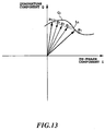
- Fig. 13 is a vector diagram showing the principle of channel estimation for the production of interference replica in an asynchronous channel.
- the channel variation is estimated by extrapolating a reception envelope line of the pilot symbol for several symbols outside a pilot symbol Pi. Since the number of the outside symbols is several symbols even considering transmission delay, no substantial error is produced even if the channel variation estimation value of the pilot symbol is adopted as a channel estimation value of the information symbol outside the pilot symbol. By using these estimation values, the spread signal replica of the information symbol outside the pilot symbol can be produced. Further, for an information symbol sandwiched between two pilot symbols, variation is estimated by interpolating the pilot symbols in the information symbol section, as in Fig. 7, to produce the spread signal replica of the information symbol.
- the received spread signal applied to an input terminal 201 is written in a reception signal memory 403.
- the memory 403 stores the reception signal in 1 pilot block time TB in Fig. 12.
- the stored reception signal is fed and despread in a matched filter 411.
- the despread signal is fed to a delay unit 413, a channel estimator 415, and a pilot frame synchronizer 419.
- the channel estimator 415 extracts a pilot symbol of known pattern from the despread signal, which is compared with the pilot symbol supplied from a pilot signal generator 417 to estimate the phase variation.
- the pilot symbol generation phase of the pilot signal generator 417 is controlled by a signal from the pilot frame synchronizer 419.
- the phase variation estimated by the channel estimator 415 is converted to a signal and fed to an interpolator 421 and an extrapolator 423.
- the estimation value estimated in the pilot section of both sides into the position of each information symbol to estimate channel variation of each information symbol.
- the estimation channel variation in the pilot section closest to the information symbol is determined as a channel variation estimation value.
- the number of information symbols even considering transmission delay in a cellular system with a cell radius of several km, is only a few.
- These channel variation estimation values are fed to a fading distortion compensator 425, multiplied to the despread signal passed through the delay unit 413 to compensate for the channel variation.
- the processing is performed on each path of this user, and the channel variation compensated despread signal of each path is fed to a RAKE combiner 430.
- the RAKE synthesized signal is decided by a data decision block 440.
- Fig. 14 is a block diagram showing the ICU of the interference canceler after the second stage of a fourth embodiment of the CDMA demodulating apparatus according to the present invention.
- the present invention eliminates interference replicas due to multipath signals of own channel.
- multipath transmission paths are formed due to reflection from buildings and ground.
- the multipath signal of own channel as in the signals from other users, also produces cross-correlation at despreading causing interference.
- the input signals of ICU of the stages after the second stage include interference replicas due to multipath signals of own channel.
- the reception signal can be separated to a number of multipath signals, and a RAKE combining function is effective.
- the signal power per 1 path of multipath is reduced, interference from multipath signals of own channel becomes not negligible. Therefore, in the multi-stage interference canceler, it is necessary to use the signal subtracted not only by interference replicas of other users but also by interference replicas due to multipath signals of own channel as an ICU input signal to improve SIR even further.
- Fig. 14 shows the ICU of k'th user of i'th stage (i being an integer of 2 or more) of the CDMA demodulating apparatus which is achieved under such a concept.
- the interference replica eliminators 504 and 505 are disposed outside and inside the ICU, but the present invention is not limited to this configuration.
- a signal subtracted by interference replicas of other users and interference replicas of multipath waves of other paths of own channel may be subtracted from the received spread signal as an input signal to the matched filter 211 in the ICU 510.
- SIR can be improved even further as compared with the first embodiment.
- reception characteristics can be improved thereby increasing the subscriber capacity of the system.
- Fig. 15 is a block diagram showing the construction of an interference canceler after the second stage of a fifth embodiment of the CDMA demodulation apparatus according to the present invention.
- the decision data outputted from a data decision block 215 is matched in amplitude with that of a desired wave to produce an interference replica of each multipath of each user in high accuracy.
- a difference of the fifth embodiment shown in Fig. 15 from the fourth embodiment shown in Fig. 14 is that a circuit for determining an amplitude value of decision data is newly provided. This point will be described below.
- a reception signal power detector 210 (521-1 - 521-Lk: Lk being the number of RAKE combining paths) determines a signal power of despread signal of each path. This can be determined as a square-law sum of amplitude of the in-phase component and quadrature component of the despread signal.
- An adder 523 adds each output of the power detector 521 of the RAKE combining multipaths to obtain a reception signal power after RAKE combining.
- An in-phase/quadrature component amplitude converter 525 determines absolute amplitude S of in-phase component and quadrature component of the reception signal from the reception signal power. Since the amplitude values of individual symbols are varied by the influence of noise, the values are averaged over 1 pilot block to obtain an amplitude value removed of the influence of noise. The averaging is achieved by an averaging unit 527. The averaged amplitude value is fed to a multiplier 529, to be adjusted so that the amplitude value of the decision data matches with the amplitude value of the reception signal.
- interference replicas of each multipath of each user can be produced with good accuracy.
- Figs. 16A and 16B are block diagrams showing the construction of a first stage interference canceling block of a sixth embodiment of th CDMA demodulating apparatus according to the present invention. Other components are similar to the construction shown in Fig. 4. That is, the matched filter 103, the received level detector 104, the channel ranking unit 105, the interference canceling blocks 107 and 108 after the second stage are similar to those in the first embodiment.
- the matched filter 103 makes correlation detection of the spreading code replica synchronized with the received spread signal of each path of each channel with the received spread signal S.
- the received level detector 104 calculates the sum of reception power of each path outputted from the matched filter 103 to detect the reception signal level of a desired wave.
- the channel ranking unit 105 outputs channel ranking information for controlling the order of demodulation of users of receiver input.
- a difference of the interference canceling block of the present embodiment from the interference canceling block shown in Fig. 5A is that the interference canceling block of first - k'th users is constructed about a decorrelator (decorrelation filter) as the center.
- matched filters 601 (601-1 - 601-k) despread signals of each path of k users from higher reception signal level according to the channel ranking information supplied from the channel ranking unit 105.
- a decorrelator 603 functions as a decorrelation filter, which outputs despread spectrum interference eliminated from each other using signals from each matched filter of each path of k users from higher reception signal level as an input spectrum according to the information from the matched filter 601 and the channel ranking unit 105.
- Coherent detector/interference production units 610 (610-1 - 610-k) has the same construction as the ICU 210 of Fig. 5A with the matched filter 211 removed, which calculates interference replicas of the first - k'th channels from the output signal of the decorrelator 603.
- the procedure is similar to the corresponding portion of the first embodiment. That is, the delay unit 203, the interference subtractor 204, and the ICU 210 are similar to those in the first embodiment.
- interference replicas are estimated according to the output of the decorrelator 603, and using the estimated interference replicas, demodulation is performed on remaining (M-k) users.
- estimated interference replicas of each user are calculated as in the first embodiment.
- the interference canceling block 108 of the last (H'th) stage outputs the reproduction data of each user.
- the decorrelator 603 makes quadrature processing on ⁇ Lk users of high reception signal level to improve the SIR of the received spread signal.
- Quadrature processing by the decorrelator 603 is performed as follows. Specifically, the decorrelator 603 produces the received spreading code replicas of each path from the spreading code of k users and the reception timing. Then, cross-correlation between ⁇ Lk spreading codes is calculated to produce a correlation matrix using the cross-correlation values. Further, an inverse matrix of this correlation matrix is calculated and applied to reception signal vectors to make quadrature processing between reception signal vectors of all paths of k users.
- signals of each path of the first user quadrate with signals of each path of 2nd - k'th users. Therefore, interference signals to each path of the first user are only residual interference signals from each path of (k+1) to M'th users, thus the SIR is improved.
- On each path of k users which is quadrature processed by the decorrelator 603 is subjected to channel variation estimation, channel variation compensation, RAKE combining, and interference replica production by the coherent detector/interference production unit 610.
- These interference replicas of k users are inputs to the ICUs 210 - (k+1) of (k+1) 'th user, which are processed as in the first embodiment.
- defect of the first embodiment is eliminated. That is, the first embodiment, the user of high reception signal level which is subjected to interference replica estimation in the first step has been disadvantageous.
- interference canceling is performed by the decorrelator 603
- the value of k is typically 2 or more, and less than the spreading factor PG, but cannot be an excessively high value. This is because the dimension of the matrix treated by the decorrelator rapidly increases as the number of channels increases.
- Figs. 17A and 17B are block diagrams showing a seventh embodiment of an interference canceling block of the CDMA demodulating apparatus according to the present invention.
- a difference of the present embodiment from the sixth embodiment is that processing of all stages to M users is carried out by a single ICU. That is, the hardware is simplified by repeatedly using a single ICU in time division.
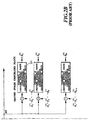
- Figs. 18A and 18B are block diagrams showing an eighth embodiment of the CDMA demodulating apparatus according to the present invention.
- the present embodiment is a simplification of the first embodiment shown in Fig. 4 and differs from the first embodiment in the following points.
- Interference-reduced signals D 1 (H) , D 2 (H) , ..., D M (H) are outputted from ICU of each channel of the interference canceling block 740 of the last stage, that is, H'th stage. These signals are inputted individually to the pilot interpolation/RAKE combining coherent detectors 750, 760 and 770 provided in each channel. Construction and operation of the detector 750 is the same as the construction and operation from the matched filter 211 to the data decision block 215' in ICU 210 of the first embodiment, which will be briefly described below.
- the PCHE (pilot symbol channel variation estimator) 752 estimates variation of each pilot symbol, which is averaged in the pilot section to be determined as a phase variation estimation value.
- the channel variation compensator 753 interpolates the phase variation estimation value into each position of information symbol sandwiched between pilot symbols to estimate the channel phase variation of each information symbol, and compensates for channel variation of information symbol section using the estimation channel phase variation to the output of the matched filter 751.
- the RAKE combiner 754 makes RAKE combination of the phase-compensated signal of each path using the reception power of each path as weighting.
- the data decision block 755 decides the RAKE synthesized signal to output reproduction data. Thus, absolute synchronization detection is achieved.
- the present embodiment unlike the above-described other embodiments, does not perform phase estimation of each path for each user of each stage. This considerably simplifies the construction of the interference canceling block of each stage. Since the interference signal replica in the present embodiment is not subjected to data decision, it is subject directly to the influence of thermal noise, however, this is nearly equivalent to the influence of decision error when the producing the reproduction data replica in the above-described other embodiments. Further, since the reproduction data replica is not produced, it is considered that in the resulting interference signal replica, influence of cross-correlation of each spreading code is transmitted to the interference canceling block of each stage, but the influence can be reduced by suppressing the number of stages of the interference canceling blocks to a few stages.
- the matched filter is used as despreading means, however, alternatively, a serial canceler of the same characteristics can be constructed using a sliding correlator.
- the portion surrounded by the broken line in Fig. 19B indicates a modification of the eighth embodiment.
- input signal to each ICU 730 of the interference canceling block 720 of the second stage is inputted the pilot interpolation/RAKE combining coherent detector 750.
- Fig. 20 is a block diagram showing a ninth embodiment of the CDMA demodulating apparatus according to the present invention.
- the present embodiment is a simplified example of the second embodiment shown in Fig. 10, and since construction and functions thereof are understood from the second and eighth embodiments, detailed description thereof is omitted.
- each communicator is subject to instantaneous variation due to fading, short period variation, and distance variation. Therefore, to satisfy the desired reception quality in a mobile station, it is necessary to make a transmission power control to control the SIR in the receiver input of the base station.
- Transmission power control is divided into an open loop type and a closed loop type.
- SIR is measured at the receiving side, and the transmission power is controlled according to the measured result.
- SIR is measured at the receiving side, and according to a difference between the measured result and a target SIR value, a transmission power control signal is transmitted to the transmission counterpart to control the transmission power of the counterpart.
- the closed loop type transmission power control is effective.
- Characteristics when the closed loop type transmission power control is applied in CDMA mobile communications are determined mainly by control delay.
- Fig. 21 is a graph showing an example of error characteristics of transmission power control when transmission power control delay is used as a parameter.
- fdT abcissas
- control error ordinates
- transmission power control does not follow the fading, and the characteristic becomes flat.
- the flat portion of control error increases. If transmission power control error increases, communication quality degrades in the section where SIR is lower than the target value, which leads to a reduction in the subscriber capacity. Therefore, it is desirable that delay of transmission power control be as small as possible.
- the multiuser interference canceler has processing delay.
- processing delay is increased with increases in the number of stages and the number of users.
- processing amount required for inverse matrix calculation increases, further, to perform quadrature processing to a plurality of past and future symbols, a processing delay of several symbols is unavoidable.
- characteristics of transmission power control are determined mainly by control delay.
- the control delay is considerably large. As a result, transmission power control error becomes large, leading to a reduction in subscriber capacity.
- Fig. 22 is a block diagram showing an embodiment of applying the transmission power control to the CDMA demodulating apparatus according to the present invention.
- a matched filter 801 performs correlation detection using the spreading code synchronized with the reception timing of each path of each communication channel to N (N being an integer of 2 or more) communicators communicating in the same frequency band.
- An SIR measuring unit 802 measures SIR of the output signal of the matched filter 801.
- a multiuser interference canceler 803 outputs an interference-eliminated signal on each communication channel.
- a reception quality measuring unit 814 measures the reception quality of the interference-eliminated signal of each channel outputted from the multiuser interference canceler 803.
- a target SIR setting unit 805 compares the reception quality outputted from the reception quality measuring unit 804 with a predetermined reception quality to set a target SIR value.
- a TPC (transmission power control) bit production unit 806 compares the reception SIR obtained from the SIR measuring unit 802 with the target SIR obtained from the target SIR setting unit 805 to produce a transmission power control signal.
- Figs. 23A and 23B are block diagrams showing details of the reception quality measuring unit 804, Fig. 23A shows the reception quality measuring unit 804 for measuring the frame error ratio to monitor the reception quality, and Fig. 23B shows the reception quality measuring unit 804 for measuring the error ratio of pilot symbol to monitor the reception quality. While transmission power control is directed to follow momentary variation to achieve the target SIR, the reception quality measuring unit 804 performs averaging over a relatively long time and monitors communication quality in the output of the interference canceler 803 to correct the target SIR value of transmission power control. Therefore, processing delay of the interference canceler 803 has no problem.
- a CRC check unit 811 performs CRC test (Cyclic Redundancy Check) of reception data outputted from the multiuser interference canceler 803. That is, reception data is inputted to the divider circuit by the produced polynomial to decide whether the remainder is zero or not. If the remainder is zero, it is decided that there was no frame error in the communication path, and if the remainder is not zero, it is decided frame error to have occurred.
- CRC test Cyclic Redundancy Check
- a frame error calculation unit 812 calculates the number of frame errors and outputs a frame error ratio.
- a frame error ratio threshold value generator 813 outputs a frame error ratio threshold value.
- a reception quality decision block 814 compares the frame error ratio with the threshold value to output a signal indicating the reception quality.
- a target SIR setting unit 805 corrects a reference SIR by this signal and outputs a corrected reference SIR.
- the reception quality measuring unit 804 by the error ratio of pilot symbol shown in Fig. 23B, comprising the following.
- a pilot symbol production unit 821 produces a pilot symbol of a known pattern.
- a pilot symbol error ratio calculation unit 822 extracts the pilot symbol from reception data outputted from the multiuser interference canceler 803, and compares it with the pilot symbol supplied from the pilot symbol production unit 822 to calculate the pilot symbol error ratio.
- the pilot symbol error ratio threshold value generator 823 outputs a threshold value of pilot symbol.
- the reception quality decision block 824 compares the pilot symbol error ratio with its threshold value and outputs a signal indicating the reception quality.
- the target SIR setting unit 805 corrects the reference SIR by the signal and outputs a corrected reference SIR.
- the matched filter 801 detects correlation of the received spreading code with the spreading code replica for each path of each communication channel and outputs the despread signal of each user.
- the SIR measuring unit 802 measures SIR of each user using the despread signal.
- the multiuser interference canceler 803 outputs the interference-eliminated despread signal using the received spread signal.
- the despread signal accompanies processing delay.
- the reception quality measuring unit 804 measures communication quality of the despread signal outputted from the interference canceler 803.
- the measured communication quality is fed to the target SIR setting 805 to be compared with a predetermined reception quality.
- Fig. 24 is a schematic view comparing the output of the matched filter 801 with the output of the interference canceler 803.
- the target SIR is set by the target SIR setting unit 805 as follows.
- the TPC bit production unit 806 compares the measured SIR outputted from the SIR measuring unit 802 with the target SIR, and when the former exceeds the latter, sends a control signal (TPC bit) to the other communicator to cause the counterpart to decrease the transmission power. On the contrary, when the latter exceeds the former, a control signal is sent to the other communicator to cause it to increase the transmission power. This can achieve closed loop transmission power control which follows instantaneous variation of the transmission path.
- the required reception quality is set for each communication channel. This is because the required communication quality differs according to the provided service (voice transmission, image transmission, data transmission, and the like).
- Fig. 25 is a block diagram showing another embodiment in which transmission power control is applied to the CDMA demodulating apparatus according to the present invention.
- the present embodiments has the following features.
- interference signals from other communicators are demodulated and decided to reproduce transmission information data replicas.
- Interference signal replicas of each channel are calculated from the reproduced data replicas, and subtracted from the reception signals to enhance SIR to the desired wave signal to be demodulated.
- the channel ranking unit 807 performs channel ranking to rearrange the communicators in the order of stronger reception power.
- the interference canceler 803 demodulates the desired wave signal in the order of stronger reception power. By performing this operation over individual stages, the later the stage, the more the SIR is improved. Further, as the accuracy of interference signal replica is improved in each stage of the interference canceler 803, variation estimation accuracy of each channel is improved. Therefore, the interference canceling effect is improved when there are a large number of communicators.
- Fig. 26 is a block diagram showing a yet further embodiment in which transmission power control is applied to the CDMA demodulating apparatus according to the present invention.
- a difference of the present embodiment from the embodiment 11 shown in Fig. 25 is that a reception quality measuring unit comprising a deinterleaver 808, a Viterbi decoder 809, and a frame error ratio measuring unit 810 is provided in place of the pilot symbol average error ratio measuring unit 804.
Claims (24)
- CDMA-Demodulationsvorrichtung zur Verwendung in einem CDMA-Kommunikationssystem, das eine Spreizung der Informationsdaten durch einen Spreizungscode mit höherer Rate als der Informationsrate in ein Breitbandsignal durchführt, wobei das Breitbandsignal zum Erreichen einer Mehrfachausnutzungsübertragung übertragen wird, wobei ein Pilotsymbol eines bekannten Musters zum Schätzen einer Kanaländerung empfangen wird, über eine Vielzahl von Kanälen empfangene individuelle Empfangssignale durch die geschätzte Kanaländerung kompensiert werden, und das kompensierte Empfangssignal zur Wiedergabe der Informationsdaten demoduliert wird,
wobei die CDMA-Demodulationsvorrichtung umfasst
eine Korrelationserfassungseinrichtung (103), die einen Spreizungscode als mit dem Empfangszeitverlauf jedes Weges jedes Kanals synchronisierte Spreizungscodereproduktion zur Korrelationserfassung der Spreizungscodereproduktion mit dem Empfangssignal jedes Weges verwendet,
eine Empfangspegelerfassungseinrichtung (104) zur Bestimmung der Summe der Empfangsleistung eines entsprechenden Weges der Korrelationserfassungseinrichtung und Erfassung des gewünschten Signalverlaufsempfangssignalpegels und
eine Kanaleinstufungseinheit (105) zur Steuerung der Reihenfolge der Demodulation des Benutzers entsprechend dem durch die Empfangspegelerfassungseinrichtung erfassten Empfangssignalpegel jedes Benutzers,
wobei die CDMA-Demodulationsvorrichtung gekennzeichnet ist durch
eine Interferenzbeseitigungseinrichtung (106 - 108) einer Vielzahl von Stufen zur Interferenzbeseitigung gemäß einem aus der Kanaleinstufungseinheit (105) ausgegebenen Steuersignal auf jeder der Vielzahl der Stufen, Durchführung einer Schätzung einer Kanaländerung unter Verwendung des Pilotsymbols auf jedem Kanal, zum Kompensieren des Empfangssignals des Kanals durch die geschätzte Kanaländerung und Neuspreizen des kompensierten Empfangssignals zur Erzeugung einer Interferenzsignalreproduktion. - CDMA-Demodulationsvorrichtung nach Anspruch 1, wobei die Interferenzbeseitigungseinrichtung (106 - 108) einer i-ten Stufe der Vielzahl der Stufen die durch die Interferenzbeseitigungseinrichtung der i-1-ten Stufe geschätzte Interferenzsignalreproduktion jedes Benutzers als Eingangssignal zum zuführen der durch die Interferenzbeseitigungseinrichtung der i-ten Stufe geschätzten Interferenzsignalreproduktionen jedes Benutzers zu der Interferenzbeseitigungseinrichtung der i+1-ten Stufe verwendet, wobei i eine ganze Zahl größer oder gleich 2 ist.
- CDMA-Demodulationsvorrichtung nach Anspruch 2, wobei jede Interferenzbeseitigungseinrichtung (106 - 108) jeder Stufe eine Unterinterferenzbeseitigungseinrichtung für jeden Benutzer zur Erzeugung der Interferenzsignalreproduktion umfasst, wobei die Unterinterferenzbeseitigungseinrichtung eines k-ten Benutzers der Interferenzbeseitigungseinrichtung der i-ten Stufe mit k gleich 1, 2, ..., M umfasst:einen Interferenzsubtrahierer (204, 224) zum Subtrahieren von Interferenzsignalreproduktionen in der Interferenzbeseitigungseinrichtung der i-ten Stufe als Interferenzsignalreproduktionen des ersten, zweiten ... und (k-1)-ten Benutzers vom Empfangssignal, Subtrahieren von Interferenzsignalreproduktionen in der Interferenzbeseitigungseinrichtung der (i-1)-ten Stufe als Interferenzreproduktionen des (k+1)-ten, ... (M-1)-ten und M-ten Benutzers vom Empfangssignal,eine Kanaländerungsschätzeinrichtung (212) zum Schätzen der Kanaländerung des Pilotsymbols im Ausgangssignal des Interferenzsubtrahierers für jeden Weg und Schätzen der Kanaländerung durch Interpolieren der Kanaländerung des geschätzten Pilotsymbols in die Position jedes Symbols der Informationsdaten im Ausgangssignal des Interferenzsubtrahierers,eine Kanaländerungskompensationseinrichtung (213) zum Kompensieren des Empfangssignals um die für jeden Weg durch die Kanaländerungsschätzeinrichtung geschätzte Kanaländerung,eine RAKE-Kombinationseinrichtung (214) zum Synthetisieren des Empfangssignals jedes Wegs, das aus der Kanaländerungskompensationseinrichtung ausgegeben wird,einen Datenentscheidungsblock (215) zur Entscheidung des Ausgangssignals der RAKE-Kombinationseinrichtung,einen Kanaländerungsaddierer (216) zum Addieren einer als Ausgabe der Kanaländerungsschätzeinrichtung erhaltenen Kanaländerung zu den aus dem Datenentscheidungsblock ausgegebenen Entscheidungsdaten,eine Neuspreizungseinrichtung (217) zum Spreizen eines aus dem Kanaländerungsaddierer ausgegebenen Signals jedes Weges durch einen mit dem Empfangszeitverlauf jedes Weges synchronisierten Spreizungscode undeinen Addierer (218) zum Addieren der Ausgabe der Neuspreizungseinrichtung zur Erzeugung einer Interferenzsignalreproduktion des k-ten Benutzers.
- CDMA-Demodulationsvorrichtung nach Anspruch 3, wobei ein Subtrahierer (505) zum Subtrahieren einer von einem j-ten Weg der k-ten Kommunikationseinrichtung auf einer (i-1)-ten Stufe verschiedenen Interferenzsignalreproduktion von dem Ausgangssignal des Interferenzsubtrahierers (504) auf der Eingangsseite der Korrelationserfassungseinrichtung (211) des j-ten Wegs vorgesehen ist, wobei j von 1 bis zu einer Weganzahl Lk der RAKE-Kombination des k-ten Benutzers der Interferenzbeseitigungseinrichtung der i-ten Stufe läuft, wobei i eine ganze Zahl größer oder gleich 2 ist.
- CDMA-Demodulationsvorrichtung nach Anspruch 3, wobei die Unterinterferenzbeseitigungseinrichtung umfasst:eine Empfangssignalleistungserfassungseinrichtung (521) zur Erfassung einer Leistung des Empfangssignals jedes Weges nach einer aus der Korrelationserfassungseinrichtung ausgegebenen Entspreizung,einen Addierer (523) zum Addieren der Empfangssignalleistungen der individuellen wege,einen Amplitudenumsetzer (525) zur Erfassung von Amplituden einer In-Phase-Komponente und einer Quadratur-Komponente aus dem Ausgangssignal des Addierers,eine Mittelungseinheit (527) zum Mitteln des Ausgangssignals des Amplitudenumsetzers undeinen Multiplizierer (529) zum Multiplizieren der Entscheidungsdaten mit einem Ausgangssignal der Mittelungseinheit.
- CDMA-Demodulationsvorrichtung nach Anspruch 1, wobei die Interferenzbeseitigungseinrichtung der ersten Stufe ein Dekorrelationsfilter (603) zur Verwendung eines Signals jedes Weges eines K-ten Benutzers aus dem höheren Empfangssignalpegel umfasst, wobei K eine ganze Zahl von 2 bis zum Spreizungsfaktor PG ist, um einen entspreizten Ausgangsvektor zu erhalten, in dem die Interferenz untereinander beseitigt ist, und
eine Kohärenzerfassungseinrichtung/Interferenzerzeugungseinrichtung (610) zum Schätzen von Übertragungsdaten von K Benutzern, die aus dem Dekorrelationsfilter ausgegeben werden, und Erzeugen eines geschätzten Interferenzausmaßes jedes Benutzers, wobei
die Interferenzbeseitigungseinrichtung die aus der Kohärenzerfassungseinrichtung/Interferenzerzeugungseinrichtung ausgegebene Interferenzsignalreproduktion als Interferenzsignalreproduktionen der K Benutzer zum Erzeugen individueller Interferenzsignalreproduktionen der verbleibenden (M-K) Benutzer verwendet. - CDMA-Demodulationsvorrichtung nach Anspruch 6, wobei die i-te Stufe der Vielzahl der Interferenzbeseitigungseinrichtungs-Stufen, die durch die Interferenzbeseitigungseinrichtung der (i-1)-ten Stufe geschätzte Interferenzsignalreproduktion jedes Benutzers als Eingangssignal verwendet, wobei i eine ganze zahl größer gleich 2 ist, und der Interferenzbeseitigungseinrichtung der (i+1)-ten Stufe ein geschätztes Interferenzausmaß jedes Benutzers zuführt, das durch die Interferenzbeseitigungseinrichtung der i-ten Stufe geschätzt wird.
- CDMA-Demodulationsvorrichtung nach Anspruch 7, wobei die Interferenzbeseitigungseinrichtung der ersten Stufe eine Unterinterferenzbeseitigungseinrichtung zur Erzeugung des geschätzten Interferenzausmaßes für jeden Benutzer nach dem (K+1)-ten Benutzer umfasst, und die Unterinterferenzbeseitigungseinrichtung des k-ten Benutzers mit k gleich (K+1), (K+2), ..., oder M umfasst
einen Interferenzsubtrahierer (204) zum Subtrahieren von Interferenzsignalreproduktionen in der Interferenzbeseitigungseinrichtung der i-ten Stufe als Interferenzsignalreproduktionen als geschätzte Interferenzausmaße des ersten, zweiten ... und K-ten Benutzers vom Empfangssignal, und Subtrahieren von Interferenzsignalreproduktionen in der Interferenzbeseitigungseinrichtung der ersten Stufe als Interferenzreproduktionen des (K+1)-, ... (k-1)-ten Benutzers vom Empfangssignal,
eine Kanaländerungsschätzeinrichtung (212) zum Schätzen der Kanaländerung des Pilotsymbols im Ausgangssignal des Interferenzsubtrahierers für jeden Weg und Schätzen der Kanaländerung jedes Informationssymbols durch Interpolieren der Kanaländerung des geschätzten Pilotsymbols in eine Position jedes Symbols der Informationsdaten im Ausgangssignal des Interferenzsubtrahierers,
eine Kanaländerungskompensationseinrichtung (213) zum Kompensieren des Empfangssignals um die für jeden Weg durch die Kanaländerungsschätzeinrichtung geschätzte Kanaländerung,
eine RAKE-Kombinationseinrichtung (214) zum Synthetisieren des aus der Kanaländerungskompensationseinrichtung ausgegebenen Empfangssignals jedes Weges,
einen Datenentscheidungsblock (215) zum Entscheiden des Ausgangssignals der RAKE-Kombinationseinrichtung,
einen Kanaländerungsaddierer (216) zum Addieren einer als Ausgangssignal der Kanaländerungsschätzeinrichtung erhaltenen Kanaländerung zu den aus dem Datenentscheidungsblock ausgegebenen Entscheidungsdaten,
eine Neuspreizungseinrichtung (217) zum Spreizen eines aus dem Kanaländerungsaddierer ausgegebenen Signals jedes Weges durch einen mit einem Empfangszeitverlauf jedes Wegs synchronisierten Spreizungscode und
einen Addierer (218) zum Addieren des Ausgangssignals der Neuspreizungseinrichtung zum Erzeugen einer Interferenzsignalreproduktionen des k-ten Benutzers,
wobei jede Interferenzbeseitigungseinrichtung der zweiten Stufe und nach der zweiten Stufe eine Unterinterferenzbeseitigungseinrichtung für jeden Benutzer zur Erzeugung der Interferenzsignalreproduktion umfasst, wobei die Unterinterferenzbeseitigungseinrichtung eines k-ten Benutzers der Interferenzbeseitigungseinrichtung der i-ten Stufe mit k gleich 1, 2, ..., M umfasst
einen Interferenzsubtrahierer (204) zum Subtrahieren von Interferenzsignalreproduktionen in der Interferenzbeseitigungseinrichtung der i-ten Stufe als Interferenzsignalreproduktionen des ersten, zweiten, ... und (k-1)-ten Benutzers vom Empfangssignal und zum Subtrahieren von Interferenzsignalreproduktionen in der Interferenzbeseitigungseinrichtung einer (i-1)-ten Stufe als interferenzreproduktionen des (k+1)-ten, ... (M-1)-ten und M-ten Benutzers vom Empfangssignal,
eine Kanaländerungsschätzeinrichtung (212) zum Schätzen einer Kanaländerung des Pilotsymbols im Ausgangssignal des Interferenzsubtrahierers für jeden Weg und Schätzen der Kanaländerung des Informationssymbols durch Interpolieren der Kanaländerung des geschätzten Pilotsymbols in die Position jedes Symbols der Informationsdaten im Ausgangssignal des Interferenzsubtrahierers,
eine Kanaländerungskompensationseinrichtung (213) zum Kompensieren des Empfangssignals um die für jeden Weg durch die Kanaländerungsschätzeinrichtung geschätzte Kanaländerung,
eine RAKE-Kombinationseinrichtung (214) zum Synthetisieren des aus der Kanaländerungskompensationseinrichtung ausgegebenen Empfangssignals jedes Wegs,
einen Datenentscheidungsblock (215) zum Entscheiden des Ausgangssignals der RAKE-Kombinationseinrichtung,
einen Kanaländerungsaddierer (216) zum Addieren einer als Ausgangssignal der Kanaländerungsschätzeinrichtung erhaltenen Kanaländerung zu den aus dem Datenentscheidungsblock ausgegebenen Entscheidungsdaten,
eine Neuspreizungseinrichtung (217) zum Spreizen eines aus dem Kanaländerungsaddierer ausgegebenen Signals jedes Weges durch einen mit dem Empfangszeitverlauf jedes Weges synchronisierten Spreizungscode und
einen Addierer (218) zum Addieren des Ausgangssignals der Neuspreizungseinrichtung zur Erzeugung einer Interferenzsignalreproduktion des k-ten Benutzers. - CDMA-Demodulationsvorrichtung nach Anspruch 1 oder 6, wobei die Korrelationserfassungseinrichtung eine Vielzahl angepasster Filter (211) umfasst.
- CDMA-Demodulationsvorrichtung nach Anspruch 1 oder 6, wobei die Korrelationserfassungseinrichtung eine Vielzahl von Gleitkorrelatoren umfasst.
- CDMA-Demodulationsvorrichtung nach Anspruch 3 oder 8, wobei die Interferenzbeseitigungseinrichtung jeder Stufe eine Einheit der Unterinterferenzbeseitigungseinrichtung und Speicher (706) zur Speicherung von Interferenzreproduktionen individueller Benutzer individueller Stufen umfasst, wobei die Unterinterferenzbeseitigungseinrichtung im Zeitmultiplex verwendet wird.
- CDMA-Demodulationsvorrichtung nach Anspruch 6, wobei die Kohärenzerfassungseinrichtung/Interferenzerzeugungseinrichtung (610) umfasst
eine Kanaländerungsschätzeinrichtung (212) zum Schätzen der Kanaländerung des Pilotsymbols im Ausgangssignal des Interferenzsubtrahierers für jeden Weg und zum Schätzen der Kanaländerung jedes Informationssymbols durch Interpolieren der Kanaländerung des geschätzten Pilotsymbols in die Position jedes Symbols der Informationsdaten im Ausgangssignal des Interferenzsubtrahierers (204, 224),
eine Kanaländerungskompensationseinrichtung (213) zum Kompensieren des Empfangssignals um die für jeden Weg durch die Kanaländerungsschätzeinrichtung geschätzte Kanaländerung,
eine RAKE-Kombinationseinrichtung (214) zum Synthetisieren des aus der Kanaländerungskompensationseinrichtung (213) ausgegebenen Empfangssignals jedes Weges,
einen Datenentscheidungsblock (215) zum Entscheiden des Ausgangssignals der RAKE-Kombinationseinrichtung,
einen Kanaländerungsaddierer (216) zum Addieren der als Ausgangssignal der Kanaländerungsschätzeinrichtung erhaltenen Kanaländerung zu den aus dem Datenentscheidungsblock ausgegebenen Entscheidungsdaten,
eine Neuspreizungseinrichtung (217) zum Spreizen eines aus dem Kanaländerungsaddierer (216) ausgegebenen Signals jedes Weges durch einen mit dem Empfangszeitverlauf jedes Weges synchronisierten Spreizungscode und
einen Addierer (218) zum Addieren des Ausgangssignals der Neuspreizungseinrichtung zur Erzeugung einer Interferenzsignalreproduktion des k-ten Benutzers. - CDMA-Demodulationsvorrichtung nach Anspruch 1, mit
einer SIR-Messeinheit (802) zum Messen einer SIR des Ausgangssignals der Korrelationserfassungseinrichtung (801),
einer Empfangsqualitätmesseinheit (804) zum Messen der Empfangsqualität des Ausgahgssignals der Interferenzbeseitigungseinrichtung (803),
einer Soll-SIR-Einstelleinheit (805) zum Einstellen einer Soll-SIR entsprechend der gemessenen Empfangsqualität und einer erforderlichen Empfangsqualität und
einer Übertragungsleistungssteuersignalerzeugungseinrichtung (806) zum Vergleichen der aus der SIR-Messeinheit (802) ausgegebenen SIR mit der Soll-SIR. - CDMA-Demodulationsvorrichtung nach Anspruch 13, wobei die SIR-Einstelleinheit (805) einen Anfangswert der Soll-SIR entsprechend der Anzahl gleichzeitiger Kommunikationseinrichtungen einstellt.
- CDMA-Demodulationsvorrichtung nach Anspruch 13, wobei die Empfangsqualitätmesseinheit (804) eine Fehlerverhältnismesseinheit (812) zum Messen eines Rahmenfehlerverhältnisses und eine Einrichtung (814) zum Vergleichen des Rahmenfehlerverhältnisses mit einem vorbestimmten Schwellenwert des Rahmenfehlerverhältnisses zur Entscheidung der Empfangsqualität umfasst.
- CDMA-Demodulationsvorrichtung nach Anspruch 13, wobei die Empfangsqualitätmesseinheit (804) eine Fehlerverhältnismesseinheit (822) zum Messen eines Bitfehlerverhältnisses des Pilotsymbols und eine Einrichtung (824) zum Vergleichen des Bitfehlerverhältnisses mit einem vorbestimmten Schwellenwert des Bitfehlerverhältnisses zur Entscheidung der Empfangsqualität umfasst.
- CDMA-Demodulationsvorrichtung nach Anspruch 13, wobei die Korrelationserfassungseinrichtung ein angepasstes Filter (801) ist.
- CDMA-Demodulationsvorrichtung nach Anspruch 14, wobei die Interferenzbeseitigungseinrichtung eine Empfangsvektorerzeugungseinrichtung zur Erzeugung eines Empfangsvektors, der das entspreizte Signals jedes Weges für jeden Kanal umfasst, aus dem Ausgangssignal des angepassten Filters, eine inverse Kreuzkorrelationsmatrixerzeugungseinrichtung zur Berechnung einer Kreuzkorrelation aller von dem Spreizungscode des eigenen Kanals des Benutzers verschiedenen Spreizungscodes und des Empfängereingangssignals der Erzeugung einer inversen Matrix einer Matrix, die durch das Aufweisen einer Kreuzkorrelation gekennzeichnet ist, und einen Matrixvektormultiplizierer zum Kompensieren des Empfangsvektors durch die inverse Matrix zur Beseitigung der Kreuzkorrelation zwischen individuellen Empfangsvektoren umfasst, um dadurch eine Interferenz zu beseitigen.
- CDMA-Demodulationsvorrichtung zur Verwendung in einem CDMA-System, das eine Mehrfachausnutzungsübertragung durch die Übertragung eines gespreizten Signals durchführt, das durch Spreizen von Informationsdaten in ein Breitbandsignal mit einem Spreizungscode erzeugt wird, dessen Rate höher als eine Informationsrate ist, wobei ein Pilotsymbol eines bekannten Musters zum Schätzen einer Kanaländerung empfangen wird, jedes über eine Vielzahl von Kanälen empfangene Empfangssignal durch die geschätzte Kanaländerung kompensiert wird, und das kompensierte Empfangssignal zum Wiedergeben der Informationsdaten demoduliert wird, wobei die Demodulationsvorrichtung umfasst
eine Korrelationserfassungseinrichtung (103), die einen Spreizungscode in Phase mit einem Empfangszeitverlauf jedes Weges jedes Kanals verwendet, zur Erfassung einer Korrelation des Spreizungscodes mit dem Empfangssignal jedes Weges,
eine Empfangspegelerfassungseinrichtung (104) zur Bestimmung einer Summe einer Empfangsleistung eines entsprechenden Weges der Korrelationserfassungseinrichtung und Erfassung eines gewünschten Signalverlaufsempfangssignalpegels,
eine Kanaleinstufungseinheit (105) zur Steuerung der Reihenfolge der Demodulation des Benutzers entsprechend dem durch die Empfangspegelerfassungseinrichtung erfassten Empfangssignalpegel jedes Benutzers und
eine Interferenzbeseitigungseinrichtung (700, 720, 740) einer Vielzahl von Stufen zur Entspreizung des Empfangssignals für individuelle Benutzer entsprechend einer Reihenfolge, die durch das aus der Kanaleinstufungseinheit ausgegebene Steuersignal bestimmt wird, zum Neuspreizen des entspreizten Signals und Subtrahieren einer durch Neuspreizen erhaltenen Interferenzsignalreproduktion anderer Benutzer vom Empfangssignal des entsprechenden Benutzers, wobei die CDMA-Demodulationsvorrichtung gekennzeichnet ist durch
eine Pilotinterpolations-/Kohärenzerfassungseinrichtung (750, 760, 770) zum Schätzen einer Kanaländerung unter Verwendung des Pilotsymbols im Signal nach der Subtraktion um ein Interferenzausmaß anderer Benutzer in der Interferenzbeseitigungseinrichtung der letzten Stufe der Vielzahl der Stufen, wobei die Informationsdaten unter Verwendung der geschätzten Kanaländerung zur Durchführung einer absoluten Synchronisationserfassung der kompensierten Informationsdaten kompensiert werden. - CDMA-Demodulationsvorrichtung nach Anspruch 19, wobei eine Interferenzbeseitigungseinrichtung der i-ten Stufe die in der Interferenzbeseitigungseinrichtung der (i-1)-ten Stufe geschätzte Interferenzsignalreproduktion jedes Benutzers als Eingangssignal zum Zuführen der in der Interferenzbeseitigungseinrichtung der i-ten Stufe geschätzten Interferenzsignalreproduktion zur Interferenzbeseitigungseinrichtung der (i+1)-ten Stufe verwendet, wobei i eine ganze Zahl größer gleich 2 ist.
- CDMA-Demodulationsvorrichtung nach Anspruch 20, wobei jede Stufe der Interferenzbeseitigungseinrichtung eine Unterinterferenzbeseitigungseinrichtung für jeden Benutzer zur Erzeugung der Interferenzsignalreproduktion umfasst, wobei die Unterinterferenzbeseitigungseinrichtung eines k-ten Benutzers der Interferenzbeseitigungseinrichtung der i-ten Stufe mit k=1, 2, ..., M umfasst
einen Interferenzsubtrahierer (204) zum Subtrahieren von Interferenzsignalreproduktionen in der Interferenzbeseitigungseinrichtung der i-ten Stufe als Interferenzsignalreproduktionen der ersten, zweiten, ... und (k-1)-ten Benutzers vom Empfangssignal, Subtrahieren von Interferenzsignalreproduktionen in der Interferenzbeseitigungseinrichtung einer (i-1)-ten Stufe als Interferenzreproduktionen des (k+1)-ten, ...(M-1)-ten und M-ten Benutzers vom Empfangssignal,
ein angepasstes Filter (211) zum Durchführen einer Korrelationserfassung zwischen dem Ausgangssignal des Interferenzsubtrahierers und einer Spreizungscodereproduktion in Phase mit dem Empfangszeitverlauf jedes Weges zum Erhalten eines entspreizten Signals jedes Weges und
eine Entspreizungs-/Kombinationseinheit (217, 218) zum spreizen des entspreizten Signals jedes Weges mit einem Spreizungscode in Phase mit dem Empfangszeitverlauf jedes Weges, Schätzen einer Interferenzsignalreproduktion des Weges jedes Benutzers und Addieren der geschätzten Interferenzsignalreproduktion zur Erzeugung einer Interferenzsignalreproduktion jedes Benutzers. - CDMA-Demodulationsvorrichtung nach Anspruch 1, 8 oder 19, wobei des Pilotsymbol periodisch zwischen die Informationsdaten eingefügt ist.
- CDMA-Demodulationsvorrichtung nach Anspruch 22, wenn dieser von Anspruch 3 abhängt, wobei die Interferenzbeseitigungseinrichtung einen Block als Verarbeitungseinheit eines Blocks konstanter Zeit mit zumindest zwei angrenzenden Pilotsignalabschnitten verwendet, und die Unterinterferenzbeseitigungseinrichtung ferner eine Extrapolationseinheit (423) für ein Informationssymbol außerhalb des Pilotsignalabschnitts zum Extrapolieren des dem Informationssymbol am nächsten liegenden Pilotsymbols zur Bestimmung einer Kanaländerung des Informationssymbols umfasst.
- CDMA-Demodulationsvorrichtung nach Anspruch 19, wobei die Interferenzbeseitigungseinrichtung jeder Stufe eine Einheit der Unterinterferenzbeseitigungseinrichtung und Speicher (305) zur Speicherung von Interferenzreproduktionen individueller Benutzer individueller Stufen umfasst, wobei die Unterinterferenzbeseitigungseinrichtung im Zeitmultiplex verwendet wird.
Applications Claiming Priority (13)
| Application Number | Priority Date | Filing Date | Title |
|---|---|---|---|
| JP14619195 | 1995-06-13 | ||
| JP14619195 | 1995-06-13 | ||
| JP146473/95 | 1995-06-13 | ||
| JP14647395 | 1995-06-13 | ||
| JP14647395 | 1995-06-13 | ||
| JP146191/95 | 1995-06-13 | ||
| JP320787/95 | 1995-12-08 | ||
| JP32078795 | 1995-12-08 | ||
| JP32078795 | 1995-12-08 | ||
| JP32588195 | 1995-12-14 | ||
| JP325881/95 | 1995-12-14 | ||
| JP32588195 | 1995-12-14 | ||
| PCT/JP1996/001582 WO1996042146A1 (fr) | 1995-06-13 | 1996-06-12 | Demodulateur amdc |
Publications (3)
| Publication Number | Publication Date |
|---|---|
| EP0776105A1 EP0776105A1 (de) | 1997-05-28 |
| EP0776105A4 EP0776105A4 (de) | 2000-08-02 |
| EP0776105B1 true EP0776105B1 (de) | 2004-08-25 |
Family
ID=27472697
Family Applications (1)
| Application Number | Title | Priority Date | Filing Date |
|---|---|---|---|
| EP96917644A Expired - Lifetime EP0776105B1 (de) | 1995-06-13 | 1996-06-12 | Cdma-demodulator |
Country Status (7)
| Country | Link |
|---|---|
| US (1) | US6137788A (de) |
| EP (1) | EP0776105B1 (de) |
| KR (1) | KR100212306B1 (de) |
| CN (1) | CN1078988C (de) |
| CA (1) | CA2197342C (de) |
| DE (1) | DE69633219T2 (de) |
| WO (1) | WO1996042146A1 (de) |
Families Citing this family (139)
| Publication number | Priority date | Publication date | Assignee | Title |
|---|---|---|---|---|
| JP2934185B2 (ja) * | 1996-03-15 | 1999-08-16 | 松下電器産業株式会社 | Cdmaセルラ無線基地局装置および移動局装置および送信方法 |
| JP2746261B2 (ja) * | 1996-06-10 | 1998-05-06 | 日本電気株式会社 | Ds−cdma干渉キャンセル装置 |
| JP3586348B2 (ja) | 1997-03-05 | 2004-11-10 | 富士通株式会社 | 信号対干渉電力比測定装置及び信号対干渉電力比測定方法並びにcdma通信方式下での送信電力制御方法 |
| EP0915575A4 (de) | 1997-03-31 | 1999-11-03 | Mitsubishi Electric Corp | Frequenzteilung in einem mobilen kommunikationssystem mit diversity-empfänger und gemeinsamen wellenkompensator |
| US6396867B1 (en) * | 1997-04-25 | 2002-05-28 | Qualcomm Incorporated | Method and apparatus for forward link power control |
| KR100258221B1 (ko) * | 1997-07-25 | 2000-06-01 | 윤종용 | 통신시스템의 패킷 트래픽 채널의 초기화 방법 |
| JP3441636B2 (ja) * | 1997-11-21 | 2003-09-02 | 株式会社エヌ・ティ・ティ・ドコモ | チャネル推定値を求める装置および方法、受信装置ならびに伝送システム |
| JPH11168408A (ja) | 1997-12-05 | 1999-06-22 | Fujitsu Ltd | 干渉キャンセラ装置 |
| JP3335900B2 (ja) * | 1998-02-27 | 2002-10-21 | 松下電器産業株式会社 | 干渉除去装置及び干渉除去方法 |
| JPH11251959A (ja) * | 1998-03-05 | 1999-09-17 | Fujitsu Ltd | 干渉キャンセラ装置及び無線通信装置 |
| JPH11266180A (ja) * | 1998-03-18 | 1999-09-28 | Fujitsu Ltd | 無線基地局のアレーアンテナシステム |
| JP2967571B1 (ja) * | 1998-05-01 | 1999-10-25 | 日本電気株式会社 | Cdmaマルチユーザ受信装置と通信システム |
| DE19824218C1 (de) * | 1998-05-29 | 2000-03-23 | Ericsson Telefon Ab L M | Multipfad-Ausbreitungsverzögerungs-Bestimmungsvorrichtung unter Verwendung von periodisch eingefügten Pilotsymbolen |
| JP3423292B2 (ja) * | 1998-05-13 | 2003-07-07 | サムスン エレクトロニクス カンパニー リミテッド | 基地局から伝送される信号を受信する移動局装置及び方法 |
| JP3728116B2 (ja) | 1998-06-02 | 2005-12-21 | キヤノン株式会社 | 通信方法及び装置 |
| JP2970656B1 (ja) * | 1998-06-25 | 1999-11-02 | 日本電気株式会社 | Ds−cdmaマルチユーザ干渉キャンセラ |
| KR100306286B1 (ko) * | 1998-08-04 | 2001-09-29 | 윤종용 | 부호분할 다중접속 통신시스템의 채널 통신 장치 및 방법 |
| US6501747B1 (en) * | 1998-08-20 | 2002-12-31 | Metawave Communications Corporation | Manifold assisted channel estimation and demodulation for CDMA systems in fast fading environments |
| JP2991196B1 (ja) * | 1998-08-24 | 1999-12-20 | 日本電気株式会社 | Cdma受信方法および受信機 |
| JP3031348B2 (ja) * | 1998-08-28 | 2000-04-10 | 日本電気株式会社 | Cdmaマルチユーザ型干渉キャンセラ |
| SG84514A1 (en) * | 1998-08-31 | 2001-11-20 | Oki Techno Ct Singapore Pte | Receiving device and channel estimator for use in a cdma communication system |
| JP3695732B2 (ja) * | 1998-09-02 | 2005-09-14 | 富士通株式会社 | Cdma受信装置のサーチ装置 |
| KR100401211B1 (ko) * | 1998-09-03 | 2004-03-30 | 삼성전자주식회사 | 부호분할다중접속통신시스템에서역방향파일럿신호의통신장치및방법 |
| JP3800382B2 (ja) * | 1998-09-04 | 2006-07-26 | 富士通株式会社 | 干渉キャンセラにおける伝搬路推定方法及び干渉除去装置 |
| US7158490B1 (en) * | 1998-09-21 | 2007-01-02 | Nokia Mobile Phones Limited | Apparatus, and associated method, for effectuating power control of a communication device |
| US6259730B1 (en) * | 1998-11-10 | 2001-07-10 | Lucent Technologies, Inc. | Transmit diversity and reception equalization for radio links |
| JP3121319B2 (ja) | 1998-12-17 | 2000-12-25 | 日本電気株式会社 | Ds−cdmaマルチユーザ干渉キャンセラとそのシステム |
| US6510190B1 (en) * | 1998-12-17 | 2003-01-21 | Nortel Networks Limited | Method and apparatus for estimating fading distortion of a signal propagating in a communication channel |
| JP2000261412A (ja) | 1999-03-06 | 2000-09-22 | Matsushita Electric Ind Co Ltd | 干渉信号除去装置 |
| ATE224616T1 (de) * | 1999-03-30 | 2002-10-15 | Nokia Corp | Schätzung des signal-/interferenz-verhältnisses in einem mobilen kommunikationssystem |
| DE60043377D1 (de) | 1999-04-02 | 2010-01-07 | Ntt Docomo Inc | Kanalschätzungsgerät und -verfahren |
| CN100517999C (zh) * | 1999-04-02 | 2009-07-22 | 株式会社Ntt都科摩 | 衰落频率判定装置和方法 |
| EP1178621A4 (de) | 1999-04-30 | 2002-06-19 | Fujitsu Ltd | Kodemultiplex-funkvorrichtung mit interferenzunterdrückung |
| US6661832B1 (en) * | 1999-05-11 | 2003-12-09 | Qualcomm Incorporated | System and method for providing an accurate estimation of received signal interference for use in wireless communications systems |
| US6529495B1 (en) | 1999-05-24 | 2003-03-04 | Nokia Telecommunications, Oy | Method and apparatus for providing differencing multistage detection in the reverse link of a code division multiple access communication system |
| BR9917357A (pt) | 1999-06-11 | 2002-02-26 | Nokia Corp | Método e aparelho para realização de uma estimativa de interferência num sistema de espectro espalhado, e, transceptor para um sistema de espectro espalhado |
| FR2795893B1 (fr) * | 1999-07-01 | 2001-08-17 | Commissariat Energie Atomique | Recepteur amrc a suppression parallele d'interferences et a synchronisation optimisee |
| JP3367475B2 (ja) * | 1999-07-06 | 2003-01-14 | 日本電気株式会社 | 無線通信機および無線通信機の消費電力制御方法 |
| US6453177B1 (en) | 1999-07-14 | 2002-09-17 | Metawave Communications Corporation | Transmitting beam forming in smart antenna array system |
| US6404760B1 (en) * | 1999-07-19 | 2002-06-11 | Qualcomm Incorporated | CDMA multiple access interference cancellation using signal estimation |
| US6633552B1 (en) * | 1999-08-06 | 2003-10-14 | Qualcomm Incorporated | Method and apparatus for determining the closed loop power control set point in a wireless packet data communication system |
| JP3373457B2 (ja) * | 1999-08-24 | 2003-02-04 | 松下電器産業株式会社 | 無線受信装置及び無線受信方法 |
| EP1145459B1 (de) * | 1999-11-26 | 2006-05-24 | Nokia Corporation | Rächenempfänger |
| DE19958383A1 (de) | 1999-12-03 | 2001-06-07 | Bosch Gmbh Robert | Verfahren zur Regelung der Sendeleistung einer Sendestation und Empfangsstation zur Durchführung des Verfahrens |
| JP3590310B2 (ja) | 1999-12-07 | 2004-11-17 | シャープ株式会社 | 連接畳込み符号復号器 |
| JP3573039B2 (ja) * | 1999-12-10 | 2004-10-06 | 株式会社日立製作所 | 無線端末位置測定方法およびそれを用いた端末装置、端末位置管理局装置 |
| FI19992694A (fi) * | 1999-12-15 | 2001-06-16 | Nokia Networks Oy | Menetelmä hajaspektrisignaalin vastaanottamiseksi ja vastaanotin |
| JP3398700B2 (ja) * | 1999-12-21 | 2003-04-21 | 埼玉日本電気株式会社 | 移動通信システムにおける送信電力制御方式 |
| EP1117186A1 (de) * | 2000-01-14 | 2001-07-18 | Lucent Technologies Inc. | Adaptiver Kodenachlauf-RAKE-Empfänger für CDMA-Nachrichtenübertragung |
| EP1117185A1 (de) * | 2000-01-14 | 2001-07-18 | Lucent Technologies Inc. | Verfahren und RAKE-Empfänger zur Kodenachführung in einem CDMA-Nachrichtenübertragungssystem |
| KR100326275B1 (ko) * | 2000-01-14 | 2002-03-08 | 전창오 | 무선 통신 시스템에서 간섭 신호 제거 장치 |
| JP2001203667A (ja) | 2000-01-18 | 2001-07-27 | Matsushita Electric Ind Co Ltd | 干渉信号除去装置および干渉信号除去方法 |
| JP2001203669A (ja) * | 2000-01-24 | 2001-07-27 | Matsushita Electric Ind Co Ltd | 無線基地局装置及び無線通信方法 |
| JP4327973B2 (ja) * | 2000-01-25 | 2009-09-09 | パナソニック株式会社 | 受信装置および受信時刻推定方法 |
| JP3686809B2 (ja) * | 2000-01-28 | 2005-08-24 | 株式会社日立コミュニケーションテクノロジー | 通信システム |
| US6885694B1 (en) | 2000-02-29 | 2005-04-26 | Telefonaktiebolaget Lm Ericsson (Publ) | Correction of received signal and interference estimates |
| EP1130792A1 (de) * | 2000-03-03 | 2001-09-05 | Lucent Technologies Inc. | Verfahren und Rake-empfänger für Phasenvektorschätzung in Kommunikationssystemen |
| EP1681775A3 (de) * | 2000-03-15 | 2008-12-03 | Interdigital Technology Corporation | Mehrbenutzerdetektion unter Verwendung einer adaptiven Kombination von gleichzeitiger Erfassung und sequentieller Interferenzunterdrückung |
| AU2001250925A1 (en) | 2000-03-21 | 2001-10-03 | Telcordia Technologies, Inc. | Combined adaptive spatio-temporal processing and multi-user detection for cdma wireless systems |
| JP2001285254A (ja) * | 2000-03-28 | 2001-10-12 | Matsushita Electric Ind Co Ltd | 通信装置及びその方法 |
| WO2001078250A1 (en) * | 2000-04-06 | 2001-10-18 | Rutgers, The State University Of New Jersey | Method and system for closed loop power control in wireless systems |
| CN1114294C (zh) | 2000-06-15 | 2003-07-09 | 华为技术有限公司 | 速度自适应信道估计方法及装置 |
| JP4574805B2 (ja) * | 2000-06-30 | 2010-11-04 | テレフオンアクチーボラゲット エル エム エリクソン(パブル) | 通信システム及びその電力制御方法 |
| US7242708B1 (en) * | 2000-10-06 | 2007-07-10 | Nokia Corporation | Equalized parallel interference cancellation EPIC for CDMA systems |
| JP3440076B2 (ja) * | 2000-11-29 | 2003-08-25 | 松下電器産業株式会社 | 無線インフラ装置 |
| US6711219B2 (en) | 2000-12-04 | 2004-03-23 | Tensorcomm, Incorporated | Interference cancellation in a signal |
| US6856945B2 (en) | 2000-12-04 | 2005-02-15 | Tensorcomm, Inc. | Method and apparatus for implementing projections in singal processing applications |
| US20020131534A1 (en) * | 2001-02-07 | 2002-09-19 | Masayuki Ariyoshi | System and method for multistage interference cancellation |
| DE10105733A1 (de) * | 2001-02-08 | 2002-09-26 | Infineon Technologies Ag | Verfahren zur Bestimmung der Störleistung in einem CDMA-Funkempfänger und CDMA-Funkempfänger |
| US7697594B2 (en) * | 2001-03-30 | 2010-04-13 | Texas Instruments Incorporated | Method and apparatus for regenerative based interference cancellation within a communication system |
| US7035201B2 (en) * | 2001-04-20 | 2006-04-25 | Mediatek Inc. | Programmable transceiver structure of multi-rate OFDM-CDMA for wireless multimedia communications |
| US6990137B2 (en) | 2001-05-17 | 2006-01-24 | Qualcomm, Incorporated | System and method for received signal prediction in wireless communications systems |
| US7170924B2 (en) | 2001-05-17 | 2007-01-30 | Qualcomm, Inc. | System and method for adjusting combiner weights using an adaptive algorithm in wireless communications system |
| US8611311B2 (en) | 2001-06-06 | 2013-12-17 | Qualcomm Incorporated | Method and apparatus for canceling pilot interference in a wireless communication system |
| US7190749B2 (en) | 2001-06-06 | 2007-03-13 | Qualcomm Incorporated | Method and apparatus for canceling pilot interference in a wireless communication system |
| US6956893B2 (en) * | 2001-08-20 | 2005-10-18 | Motorola, Inc. | Linear minimum mean square error equalization with interference cancellation for mobile communication forward links utilizing orthogonal codes covered by long pseudorandom spreading codes |
| JP4072910B2 (ja) * | 2001-08-21 | 2008-04-09 | インフィネオン テヒノロジース アクチェンゲゼルシャフト | 拡散スペクトル通信システムにおいてデータ速度を増大させる方法及び装置 |
| US8085889B1 (en) | 2005-04-11 | 2011-12-27 | Rambus Inc. | Methods for managing alignment and latency in interference cancellation |
| US7158559B2 (en) * | 2002-01-15 | 2007-01-02 | Tensor Comm, Inc. | Serial cancellation receiver design for a coded signal processing engine |
| WO2003044969A2 (en) | 2001-11-16 | 2003-05-30 | Tensorcomm Incorporated | Construction of an interference matrix for a coded signal processing engine |
| US7580448B2 (en) | 2002-10-15 | 2009-08-25 | Tensorcomm, Inc | Method and apparatus for channel amplitude estimation and interference vector construction |
| US7394879B2 (en) | 2001-11-19 | 2008-07-01 | Tensorcomm, Inc. | Systems and methods for parallel signal cancellation |
| US7260506B2 (en) | 2001-11-19 | 2007-08-21 | Tensorcomm, Inc. | Orthogonalization and directional filtering |
| US7039136B2 (en) * | 2001-11-19 | 2006-05-02 | Tensorcomm, Inc. | Interference cancellation in a signal |
| US7787518B2 (en) | 2002-09-23 | 2010-08-31 | Rambus Inc. | Method and apparatus for selectively applying interference cancellation in spread spectrum systems |
| AU2002358155A1 (en) * | 2001-12-21 | 2003-07-09 | Telefonaktiebogalet Lm Ericsson (Publ) | Power control in mobile radio communications systems |
| GB2384664B (en) * | 2002-01-25 | 2004-12-22 | Toshiba Res Europ Ltd | Receiver processing systems |
| GB2384661B (en) * | 2002-01-25 | 2005-04-20 | Toshiba Res Europ Ltd | Receiver processing systems |
| GB2384662B (en) * | 2002-01-25 | 2004-03-24 | Toshiba Res Europ Ltd | Receiver processing systems |
| GB2384660B (en) * | 2002-01-25 | 2004-11-17 | Toshiba Res Europ Ltd | Reciever processing systems |
| GB2384665B (en) | 2002-01-25 | 2004-11-17 | Toshiba Res Europ Ltd | Reciever processing systems |
| JP4025979B2 (ja) * | 2002-04-24 | 2007-12-26 | 日本電気株式会社 | Cdma移動通信方式における送信電力制御方法および無線基地局とcdma通信システム |
| FR2840142B1 (fr) * | 2002-05-24 | 2004-09-10 | Dibcom | Procede et dispositif de synchronisation a la reception d'un signal et d'echos |
| US20040010746A1 (en) * | 2002-07-10 | 2004-01-15 | Lucas L. Victor | Forward error correction system for wireless communications |
| KR100575710B1 (ko) * | 2002-07-20 | 2006-05-03 | 엘지전자 주식회사 | 업링크 동기 검출방법 |
| US7463609B2 (en) | 2005-07-29 | 2008-12-09 | Tensorcomm, Inc | Interference cancellation within wireless transceivers |
| US7577186B2 (en) | 2002-09-20 | 2009-08-18 | Tensorcomm, Inc | Interference matrix construction |
| US8761321B2 (en) | 2005-04-07 | 2014-06-24 | Iii Holdings 1, Llc | Optimal feedback weighting for soft-decision cancellers |
| US7808937B2 (en) | 2005-04-07 | 2010-10-05 | Rambus, Inc. | Variable interference cancellation technology for CDMA systems |
| US7876810B2 (en) | 2005-04-07 | 2011-01-25 | Rambus Inc. | Soft weighted interference cancellation for CDMA systems |
| US7787572B2 (en) | 2005-04-07 | 2010-08-31 | Rambus Inc. | Advanced signal processors for interference cancellation in baseband receivers |
| US8005128B1 (en) | 2003-09-23 | 2011-08-23 | Rambus Inc. | Methods for estimation and interference cancellation for signal processing |
| US8179946B2 (en) | 2003-09-23 | 2012-05-15 | Rambus Inc. | Systems and methods for control of advanced receivers |
| FR2845217B1 (fr) * | 2002-09-27 | 2004-12-17 | St Microelectronics Sa | Procede de traitement d'un signal incident au sein d'un recepteur "rake" a plusieurs doigts, et recepteur "rake" correspondant |
| AU2003301493A1 (en) | 2002-10-15 | 2004-05-04 | Tensorcomm Inc. | Method and apparatus for interference suppression with efficient matrix inversion in a ds-cdma system |
| US7440490B2 (en) * | 2002-12-18 | 2008-10-21 | Anna Kidiyarova-Shevchenko | Method and apparatus for multi-user detection using RSFQ successive interference cancellation in CDMA wireless systems |
| US7346103B2 (en) * | 2003-03-03 | 2008-03-18 | Interdigital Technology Corporation | Multi user detection using equalization and successive interference cancellation |
| US6985535B2 (en) * | 2003-10-31 | 2006-01-10 | Motorola, Inc. | Channel condition estimation for pilot coefficient selection |
| JP4297780B2 (ja) * | 2003-12-22 | 2009-07-15 | 株式会社ルネサステクノロジ | 受信装置 |
| US7477710B2 (en) | 2004-01-23 | 2009-01-13 | Tensorcomm, Inc | Systems and methods for analog to digital conversion with a signal cancellation system of a receiver |
| JP2005311797A (ja) * | 2004-04-22 | 2005-11-04 | Tektronix Japan Ltd | 逆拡散方法 |
| US7773950B2 (en) | 2004-06-16 | 2010-08-10 | Telefonaktiebolaget Lm Ericsson (Publ) | Benign interference suppression for received signal quality estimation |
| US8599972B2 (en) * | 2004-06-16 | 2013-12-03 | Telefonaktiebolaget L M Ericsson (Publ) | SIR estimation in a wireless receiver |
| JP4549162B2 (ja) * | 2004-11-15 | 2010-09-22 | パナソニック株式会社 | 無線基地局装置及び無線通信方法 |
| US8422955B2 (en) | 2004-12-23 | 2013-04-16 | Qualcomm Incorporated | Channel estimation for interference cancellation |
| US8099123B2 (en) * | 2004-12-23 | 2012-01-17 | Qualcomm Incorporated | Adaptation of transmit subchannel gains in a system with interference cancellation |
| US8442441B2 (en) | 2004-12-23 | 2013-05-14 | Qualcomm Incorporated | Traffic interference cancellation |
| US8406695B2 (en) | 2004-12-23 | 2013-03-26 | Qualcomm Incorporated | Joint interference cancellation of pilot, overhead and traffic channels |
| EP1684440B1 (de) * | 2005-01-21 | 2008-09-17 | STMicroelectronics N.V. | Verfahren und Vorrichtung zur Dekodierung eines empfangenen UWB-Signals mit Nachbarsymbolinterferenz |
| US7826516B2 (en) | 2005-11-15 | 2010-11-02 | Rambus Inc. | Iterative interference canceller for wireless multiple-access systems with multiple receive antennas |
| US8472877B2 (en) | 2005-10-24 | 2013-06-25 | Qualcomm Incorporated | Iterative interference cancellation system and method |
| US8385388B2 (en) | 2005-12-06 | 2013-02-26 | Qualcomm Incorporated | Method and system for signal reconstruction from spatially and temporally correlated received samples |
| JP2007295549A (ja) * | 2006-03-31 | 2007-11-08 | Matsushita Electric Ind Co Ltd | Mimo受信装置およびmimo通信システム |
| US8781043B2 (en) * | 2006-11-15 | 2014-07-15 | Qualcomm Incorporated | Successive equalization and cancellation and successive mini multi-user detection for wireless communication |
| US7991041B2 (en) * | 2006-11-15 | 2011-08-02 | Qualcomm, Incorporated | Iterative detection and cancellation for wireless communication |
| JP4769698B2 (ja) * | 2006-11-30 | 2011-09-07 | 富士通株式会社 | 干渉電力推定装置及び干渉電力推定方法 |
| US9509366B2 (en) * | 2007-04-04 | 2016-11-29 | Via Technologies, Inc. | Interference estimation circuit and method |
| US20090190633A1 (en) * | 2008-01-24 | 2009-07-30 | Smith Francis J | Interference mitigation of signals within the same frequency spectrum |
| US9887864B1 (en) * | 2014-03-10 | 2018-02-06 | Origin Wireless, Inc. | Methods, devices and systems of heterogeneous time-reversal paradigm enabling direct connectivity in internet of things |
| US9559874B2 (en) | 2013-08-16 | 2017-01-31 | Origin Wireless, Inc. | Multiuser time-reversal division multiple access uplink system with parallel interference cancellation |
| US9226304B2 (en) * | 2014-03-10 | 2015-12-29 | Origin Wireless, Inc. | Time-reversal wireless paradigm for internet of things |
| US8306164B2 (en) * | 2009-02-11 | 2012-11-06 | Alcatel Lucent | Interference cancellation with a time-sliced architecture |
| WO2011063567A1 (en) | 2009-11-27 | 2011-06-03 | Qualcomm Incorporated | Interference cancellation for non-orthogonal channel sets |
| US9544083B2 (en) | 2011-11-21 | 2017-01-10 | Broadcom Corporation | Secondary synchronization signal detection with interference cancelation for LTE |
| CN102545958B (zh) * | 2011-12-30 | 2014-09-17 | 华为技术有限公司 | 信号处理单元及干扰对消方法、装置、系统 |
| US9351260B2 (en) | 2012-06-14 | 2016-05-24 | Telefonaktiebolaget L M Ericsson (Publ) | Transmit power control |
| EP2690809A1 (de) * | 2012-07-23 | 2014-01-29 | Broadcom Corporation | Erkennung von Sekundärsynchronisationssignalen mit Interferenzunterdrückung für LTE |
| CN103152300A (zh) * | 2013-03-13 | 2013-06-12 | 中国航天科技集团公司第九研究院第七七一研究所 | 一种基于导频的ofdm接收器及其信道均衡方法 |
| CN111106842B (zh) * | 2018-10-25 | 2022-04-22 | 中兴通讯股份有限公司 | 一种消除邻近信道干扰的方法、电子设备和可读存储介质 |
Family Cites Families (14)
| Publication number | Priority date | Publication date | Assignee | Title |
|---|---|---|---|---|
| US5151919A (en) * | 1990-12-17 | 1992-09-29 | Ericsson-Ge Mobile Communications Holding Inc. | Cdma subtractive demodulation |
| US5105435A (en) * | 1990-12-21 | 1992-04-14 | Motorola, Inc. | Method and apparatus for cancelling spread-spectrum noise |
| US5235612A (en) * | 1990-12-21 | 1993-08-10 | Motorola, Inc. | Method and apparatus for cancelling spread-spectrum noise |
| US5224122A (en) * | 1992-06-29 | 1993-06-29 | Motorola, Inc. | Method and apparatus for canceling spread-spectrum noise |
| US5406585A (en) * | 1992-11-30 | 1995-04-11 | Motorola, Inc. | Method and apparatus for trellis decoding in a multiple-access system |
| JP2508587B2 (ja) * | 1993-06-14 | 1996-06-19 | 日本電気株式会社 | スペクトル拡散受信装置 |
| GB2279851B (en) * | 1993-07-01 | 1997-10-01 | Roke Manor Research | Threshold cancellation means for use in digital mobile radio networks |
| JP2938337B2 (ja) * | 1994-03-09 | 1999-08-23 | 三菱電機株式会社 | スペクトル拡散通信用データ復調回路 |
| JPH07264111A (ja) * | 1994-03-18 | 1995-10-13 | Oki Electric Ind Co Ltd | 符号分割多元接続受信装置 |
| JPH07264112A (ja) * | 1994-03-18 | 1995-10-13 | Oki Electric Ind Co Ltd | 符号分割多元接続通信の干渉除去方法 |
| JPH07273713A (ja) * | 1994-04-04 | 1995-10-20 | Oki Electric Ind Co Ltd | 受信装置、基地局受信システム及び移動局受信システム |
| JP2877248B2 (ja) * | 1994-05-20 | 1999-03-31 | エヌ・ティ・ティ移動通信網株式会社 | Cdmaシステムにおける送信電力制御方法および装置 |
| US5872776A (en) * | 1995-11-22 | 1999-02-16 | Yang; Lin-Lang | Signal detection and interference cancellation based on simplified matrix inversion for CDMA applications |
| JP2850858B2 (ja) * | 1996-06-21 | 1999-01-27 | 日本電気株式会社 | Cdma送受信方式 |
-
1996
- 1996-06-12 KR KR1019970700970A patent/KR100212306B1/ko not_active IP Right Cessation
- 1996-06-12 WO PCT/JP1996/001582 patent/WO1996042146A1/ja active IP Right Grant
- 1996-06-12 CA CA002197342A patent/CA2197342C/en not_active Expired - Fee Related
- 1996-06-12 CN CN96190729A patent/CN1078988C/zh not_active Expired - Fee Related
- 1996-06-12 DE DE69633219T patent/DE69633219T2/de not_active Expired - Lifetime
- 1996-06-12 US US08/793,051 patent/US6137788A/en not_active Expired - Lifetime
- 1996-06-12 EP EP96917644A patent/EP0776105B1/de not_active Expired - Lifetime
Also Published As
| Publication number | Publication date |
|---|---|
| US6137788A (en) | 2000-10-24 |
| DE69633219T2 (de) | 2005-08-25 |
| KR100212306B1 (ko) | 1999-08-02 |
| CA2197342C (en) | 2001-11-06 |
| EP0776105A4 (de) | 2000-08-02 |
| KR970705258A (ko) | 1997-09-06 |
| DE69633219D1 (en) | 2004-09-30 |
| WO1996042146A1 (fr) | 1996-12-27 |
| CN1158193A (zh) | 1997-08-27 |
| CN1078988C (zh) | 2002-02-06 |
| CA2197342A1 (en) | 1996-12-27 |
| EP0776105A1 (de) | 1997-05-28 |
Similar Documents
| Publication | Publication Date | Title |
|---|---|---|
| EP0776105B1 (de) | Cdma-demodulator | |
| KR100364886B1 (ko) | Ds-cdma 멀티유저 간섭캔슬러 및 그것을 이용하는cdma 멀티유저 시스템 | |
| US6584115B1 (en) | Multiuser interference canceler for DS-CDMA system | |
| KR100263977B1 (ko) | 멀티스테이지형 간섭 상쇄기 | |
| JP4574805B2 (ja) | 通信システム及びその電力制御方法 | |
| US6473451B1 (en) | Signal to interference power ratio measuring apparatus and signal to interference power ratio measuring method as well as transmission power controlling method under CDMA communication system | |
| JP2914445B2 (ja) | Cdma適応受信装置 | |
| CA2281733C (en) | Rake receiver for direct spreading cdma transmission | |
| US20020154717A1 (en) | Weighting factor setting method for subtractive interference canceller, interference canceller unit using said weighting factor and interference canceller | |
| US6526271B1 (en) | Method and apparatus for interference rejection | |
| US6272167B1 (en) | Spread spectrum communication system | |
| US6920173B2 (en) | Spread-spectrum signal receiver apparatus and interference cancellation apparatus | |
| JP3228405B2 (ja) | 直接拡散cdma伝送方式の受信機 | |
| KR980012986A (ko) | 코드분할 다중접속기(씨디엠에이) 수신장치 | |
| GB2411546A (en) | Interference cancellation in CDMA system | |
| US6667964B1 (en) | Propagation path-estimation method for an interference canceler and interference elimination apparatus | |
| JPH08335899A (ja) | Cdma復調回路 | |
| Latva-aho et al. | Delay trackers for multiuser CDMA receivers | |
| EP1047201B1 (de) | CDMA Empfänger | |
| JP2855173B2 (ja) | Cdma復調装置 | |
| JPH08335898A (ja) | Cdma信号受信機 | |
| JP2001024553A (ja) | Cdma受信装置の干渉キャンセラ装置 |
Legal Events
| Date | Code | Title | Description |
|---|---|---|---|
| PUAI | Public reference made under article 153(3) epc to a published international application that has entered the european phase |
Free format text: ORIGINAL CODE: 0009012 |
|
| 17P | Request for examination filed |
Effective date: 19970226 |
|
| AK | Designated contracting states |
Kind code of ref document: A1 Designated state(s): DE FR GB IT SE |
|
| A4 | Supplementary search report drawn up and despatched |
Effective date: 20000619 |
|
| AK | Designated contracting states |
Kind code of ref document: A4 Designated state(s): DE FR GB IT SE |
|
| RIC1 | Information provided on ipc code assigned before grant |
Free format text: 7H 04J 13/04 A, 7H 04B 1/707 B |
|
| RAP1 | Party data changed (applicant data changed or rights of an application transferred) |
Owner name: NTT DOCOMO, INC. |
|
| 17Q | First examination report despatched |
Effective date: 20030423 |
|
| GRAP | Despatch of communication of intention to grant a patent |
Free format text: ORIGINAL CODE: EPIDOSNIGR1 |
|
| GRAS | Grant fee paid |
Free format text: ORIGINAL CODE: EPIDOSNIGR3 |
|
| RIC1 | Information provided on ipc code assigned before grant |
Ipc: 7H 04B 1/707 A |
|
| GRAA | (expected) grant |
Free format text: ORIGINAL CODE: 0009210 |
|
| AK | Designated contracting states |
Kind code of ref document: B1 Designated state(s): DE FR GB IT SE |
|
| REG | Reference to a national code |
Ref country code: GB Ref legal event code: FG4D |
|
| REF | Corresponds to: |
Ref document number: 69633219 Country of ref document: DE Date of ref document: 20040930 Kind code of ref document: P |
|
| REG | Reference to a national code |
Ref country code: SE Ref legal event code: TRGR |
|
| ET | Fr: translation filed | ||
| PLBE | No opposition filed within time limit |
Free format text: ORIGINAL CODE: 0009261 |
|
| STAA | Information on the status of an ep patent application or granted ep patent |
Free format text: STATUS: NO OPPOSITION FILED WITHIN TIME LIMIT |
|
| 26N | No opposition filed |
Effective date: 20050526 |
|
| PGFP | Annual fee paid to national office [announced via postgrant information from national office to epo] |
Ref country code: DE Payment date: 20120607 Year of fee payment: 17 |
|
| PGFP | Annual fee paid to national office [announced via postgrant information from national office to epo] |
Ref country code: SE Payment date: 20120612 Year of fee payment: 17 Ref country code: GB Payment date: 20120606 Year of fee payment: 17 Ref country code: FR Payment date: 20120619 Year of fee payment: 17 |
|
| PGFP | Annual fee paid to national office [announced via postgrant information from national office to epo] |
Ref country code: IT Payment date: 20120613 Year of fee payment: 17 |
|
| PG25 | Lapsed in a contracting state [announced via postgrant information from national office to epo] |
Ref country code: SE Free format text: LAPSE BECAUSE OF NON-PAYMENT OF DUE FEES Effective date: 20130613 |
|
| REG | Reference to a national code |
Ref country code: SE Ref legal event code: EUG |
|
| GBPC | Gb: european patent ceased through non-payment of renewal fee |
Effective date: 20130612 |
|
| REG | Reference to a national code |
Ref country code: FR Ref legal event code: ST Effective date: 20140228 |
|
| REG | Reference to a national code |
Ref country code: DE Ref legal event code: R119 Ref document number: 69633219 Country of ref document: DE Effective date: 20140101 |
|
| PG25 | Lapsed in a contracting state [announced via postgrant information from national office to epo] |
Ref country code: DE Free format text: LAPSE BECAUSE OF NON-PAYMENT OF DUE FEES Effective date: 20140101 Ref country code: GB Free format text: LAPSE BECAUSE OF NON-PAYMENT OF DUE FEES Effective date: 20130612 |
|
| PG25 | Lapsed in a contracting state [announced via postgrant information from national office to epo] |
Ref country code: FR Free format text: LAPSE BECAUSE OF NON-PAYMENT OF DUE FEES Effective date: 20130701 Ref country code: IT Free format text: LAPSE BECAUSE OF NON-PAYMENT OF DUE FEES Effective date: 20130612 |