EP0741345B1 - Verfahren und Vorrichtung zur Regelung eines Prozesses - Google Patents
Verfahren und Vorrichtung zur Regelung eines Prozesses Download PDFInfo
- Publication number
- EP0741345B1 EP0741345B1 EP96106969A EP96106969A EP0741345B1 EP 0741345 B1 EP0741345 B1 EP 0741345B1 EP 96106969 A EP96106969 A EP 96106969A EP 96106969 A EP96106969 A EP 96106969A EP 0741345 B1 EP0741345 B1 EP 0741345B1
- Authority
- EP
- European Patent Office
- Prior art keywords
- variable
- value
- waiting time
- adjustable variable
- time
- Prior art date
- Legal status (The legal status is an assumption and is not a legal conclusion. Google has not performed a legal analysis and makes no representation as to the accuracy of the status listed.)
- Expired - Lifetime
Links
- 238000000034 method Methods 0.000 title claims abstract description 97
- 230000008569 process Effects 0.000 title claims abstract description 69
- 230000008859 change Effects 0.000 claims description 29
- 230000006399 behavior Effects 0.000 claims description 14
- 230000006870 function Effects 0.000 claims description 10
- 230000015654 memory Effects 0.000 claims description 10
- 238000010521 absorption reaction Methods 0.000 claims description 5
- 238000010257 thawing Methods 0.000 claims description 4
- 230000001419 dependent effect Effects 0.000 claims description 3
- 238000005070 sampling Methods 0.000 claims 5
- 238000009877 rendering Methods 0.000 claims 3
- 230000000630 rising effect Effects 0.000 claims 1
- 238000001816 cooling Methods 0.000 description 17
- 230000000694 effects Effects 0.000 description 13
- 239000006096 absorbing agent Substances 0.000 description 5
- 238000010586 diagram Methods 0.000 description 4
- 230000001105 regulatory effect Effects 0.000 description 4
- 238000002485 combustion reaction Methods 0.000 description 3
- 230000002123 temporal effect Effects 0.000 description 3
- 238000006243 chemical reaction Methods 0.000 description 2
- 230000004048 modification Effects 0.000 description 2
- 238000012986 modification Methods 0.000 description 2
- 230000004044 response Effects 0.000 description 2
- 230000008901 benefit Effects 0.000 description 1
- 238000001311 chemical methods and process Methods 0.000 description 1
- 230000001143 conditioned effect Effects 0.000 description 1
- 230000001276 controlling effect Effects 0.000 description 1
- 239000000446 fuel Substances 0.000 description 1
- 238000010438 heat treatment Methods 0.000 description 1
- 238000002347 injection Methods 0.000 description 1
- 239000007924 injection Substances 0.000 description 1
- 230000010355 oscillation Effects 0.000 description 1
- 230000000149 penetrating effect Effects 0.000 description 1
- 230000007363 regulatory process Effects 0.000 description 1
- 238000011144 upstream manufacturing Methods 0.000 description 1
Images

Classifications
-
- G—PHYSICS
- G05—CONTROLLING; REGULATING
- G05B—CONTROL OR REGULATING SYSTEMS IN GENERAL; FUNCTIONAL ELEMENTS OF SUCH SYSTEMS; MONITORING OR TESTING ARRANGEMENTS FOR SUCH SYSTEMS OR ELEMENTS
- G05B13/00—Adaptive control systems, i.e. systems automatically adjusting themselves to have a performance which is optimum according to some preassigned criterion
- G05B13/02—Adaptive control systems, i.e. systems automatically adjusting themselves to have a performance which is optimum according to some preassigned criterion electric
- G05B13/0205—Adaptive control systems, i.e. systems automatically adjusting themselves to have a performance which is optimum according to some preassigned criterion electric not using a model or a simulator of the controlled system
- G05B13/024—Adaptive control systems, i.e. systems automatically adjusting themselves to have a performance which is optimum according to some preassigned criterion electric not using a model or a simulator of the controlled system in which a parameter or coefficient is automatically adjusted to optimise the performance
-
- F—MECHANICAL ENGINEERING; LIGHTING; HEATING; WEAPONS; BLASTING
- F25—REFRIGERATION OR COOLING; COMBINED HEATING AND REFRIGERATION SYSTEMS; HEAT PUMP SYSTEMS; MANUFACTURE OR STORAGE OF ICE; LIQUEFACTION SOLIDIFICATION OF GASES
- F25B—REFRIGERATION MACHINES, PLANTS OR SYSTEMS; COMBINED HEATING AND REFRIGERATION SYSTEMS; HEAT PUMP SYSTEMS
- F25B49/00—Arrangement or mounting of control or safety devices
- F25B49/04—Arrangement or mounting of control or safety devices for sorption type machines, plants or systems
-
- G—PHYSICS
- G05—CONTROLLING; REGULATING
- G05B—CONTROL OR REGULATING SYSTEMS IN GENERAL; FUNCTIONAL ELEMENTS OF SUCH SYSTEMS; MONITORING OR TESTING ARRANGEMENTS FOR SUCH SYSTEMS OR ELEMENTS
- G05B13/00—Adaptive control systems, i.e. systems automatically adjusting themselves to have a performance which is optimum according to some preassigned criterion
- G05B13/02—Adaptive control systems, i.e. systems automatically adjusting themselves to have a performance which is optimum according to some preassigned criterion electric
- G05B13/0265—Adaptive control systems, i.e. systems automatically adjusting themselves to have a performance which is optimum according to some preassigned criterion electric the criterion being a learning criterion
- G05B13/0275—Adaptive control systems, i.e. systems automatically adjusting themselves to have a performance which is optimum according to some preassigned criterion electric the criterion being a learning criterion using fuzzy logic only
-
- Y—GENERAL TAGGING OF NEW TECHNOLOGICAL DEVELOPMENTS; GENERAL TAGGING OF CROSS-SECTIONAL TECHNOLOGIES SPANNING OVER SEVERAL SECTIONS OF THE IPC; TECHNICAL SUBJECTS COVERED BY FORMER USPC CROSS-REFERENCE ART COLLECTIONS [XRACs] AND DIGESTS
- Y10—TECHNICAL SUBJECTS COVERED BY FORMER USPC
- Y10S—TECHNICAL SUBJECTS COVERED BY FORMER USPC CROSS-REFERENCE ART COLLECTIONS [XRACs] AND DIGESTS
- Y10S706/00—Data processing: artificial intelligence
- Y10S706/90—Fuzzy logic
Definitions
- the present invention relates to a method for regulating an output of a process and a device to carry out such a method according to the preamble of claim 1 or 18.
- a method or device are known from DE 29 05 525.
- Das inventive method or the inventive Device are used for example in the Regulation of the interior temperature of a Absorber refrigerator.
- a process generally has an output, which can be influenced via an input variable of the process is.
- the term "process” stands for any kind of Controlled system, for example an internal combustion engine, Electric motor, a cooling unit or a refrigerator, for chemical processes, etc.
- the term "manipulated variable” relates refer to physical quantities, which are immediate can be changed to an indirect in this way Change the output of the process.
- the term “output variable” stands for a physical Size that is not directly influenced, but rather about a change in the manipulated variable.
- manipulated variables such as Throttle valve position or the fuel injection quantity, while the output variable is the speed, the torque or the output is.
- Absorber refrigerator is the manipulated variable about that Cooker of the absorption cooling unit supplied heat or electrical power while the output quantity for example the interior temperature of the refrigerator is.
- Processes of the kind in which the present invention pertains relates generally to the influence of disturbance variables, which affect the initial size of the process.
- the indirect control makes the influence of disturbance variables difficult the output variable via the manipulated variable or makes one such control impossible.
- Examples of disturbances are about in the case of the internal combustion engine pressure, temperature and Changes in humidity of the intake air, changes in Engine temperature, etc.
- a refrigerator for example penetrating when opening the refrigerator, warmer air, fluctuations in ambient temperature, etc. a disruptive influence on the interior temperature.
- the interior temperature shows one Absorber refrigerator such behavior, i.e. size Dead times and delay times.
- the initial size Indoor temperature only reacts very indirectly to one Modification of the absorption chiller cooker supplied power, which is the manipulated variable here.
- the process parameter T v occurring in this model represents the Delay time of the process and is a measure of the approximation speed of the output variable y to its stationary value a.
- this model does not represent a complete and exact process description, in particular in the case of non-linear processes, which are predominantly found in reality, and the invention is not limited to the regulation of such modelable processes.
- the object of the present invention is to provide a method and a device for regulating an output variable of a process which has large dead times T tot and large delay times T v , so that the output variable shows both good control behavior in the case of setpoint changes and also quickly influences disturbances and can be adjusted with little overshoot.
- a current one Manipulated variable calculated in an activity phase of the regulation process.
- This phase of activity follows an inactivity phase during which the Manipulated variable is not changed.
- the inactivity phase then the next activity phase of the controller closes on.
- At the end of each activity phase there is a newly calculated one Manipulated variable available.
- the course of the manipulated variable preferably goes into duration between the calculations of manipulated variables. Prefers this duration depends on the amount of the difference between the currently calculated manipulated variable and one in one preceding activity phase calculated manipulated variable, the previously calculated manipulated variable preferably being the in the current activity phase immediately preceding activity phase is calculated manipulated variable.
- the controller has a memory for previously calculated manipulated variable, and a facility to calculate the difference between the stored previous manipulated variable and the currently calculated manipulated variable.
- the controller also includes a timer that determines the duration between successive manipulated variables and thus the Sequence of activity and inactivity phases of the controller controls.
- the timer receives the difference between earlier and currently calculated manipulated variable and varies the waiting time until the next manipulated variable calculation corresponding. For example, the Functions of calculating a current manipulated variable and the timer function from a microprocessor carried out.
- the waiting time is preferably between the current one Manipulated variable calculation and the next Manipulated variable calculation a monotonously increasing dependency of the amount of the difference between the currently calculated Manipulated variable and the one calculated immediately before Manipulated variable. For example, there are two for the wait different lengths of time are provided, and the shorter waiting time is chosen in the event that the Difference between current and previous manipulated variable is less than a predetermined threshold. Otherwise is used during the longer period until the calculation of the next manipulated variable waited.
- delay time and / or dead time of the process also go in the calculation of the waiting time.
- the Process parameters dead time and delay time can for example, be recorded from the course of the Output of the process in response to one Output step.
- the manipulated variable depends on the setpoint deviation of the Output variable calculates and preferably closes more Input variables, for example the change over time the output variable and / or a previous manipulated variable, for example the manipulated variable calculated immediately before.
- the controller points for example for the calculation of the Waiting time and / or for calculating the manipulated variable corresponding maps on or used for calculation fuzzy-logical processes including fuzzification the calculation of the manipulated variable or waiting time inflowing input variables, application of a basis of Rules on the fuzzified input variables and Defuzzification of the fuzzy set obtained Output variable to get the value of the output variable.
- the inventive method and the inventive Devices are advantageously suitable for regulation the temperature of the air inside a Absorber refrigerator.
- FIG. 2 shows an embodiment of a controller 1 of present invention, which is used, the Indoor temperature in a refrigerator or cold room 3 too regulate.
- the refrigerator has an evaporator 4, which is in connection with a cooling unit 2, such as one Absorption cooling unit to heat the cold room 3 revoke.
- a Temperature sensor 5 arranged, which the air temperature detected in the refrigerator.
- the recorded air temperature is called Output variable (actual value X) entered in controller 1.
- the Controller 1 receives a set temperature value w from a suitable actuator 6. Depending on these The controller calculates a value for the input variables Control variable Y, which the cooling unit 2 continuously power supplied. This manipulated variable has an influence taken on by means of a cooling unit and evaporator achieved cooling effect in the cooling room 3.
- the Performance over the duty cycle of an intermittent by a heating element of the stove Absorption cooling unit flowing electrical current or when using AC over the Current flow angle set.
- the frequency of the intermittent current is sufficiently high chosen so that by the integrating properties the stove has a quasi-continuous power supply results.
- the cooling circuit with cooling unit 2 and evaporator 4 has considerable dead times.
- a change in the manipulated variable leads to a noticeable only after this dead time has elapsed Change in temperature of the evaporator 4.
- Conditioned by the poor thermal conductivity of air also arises a significant delay in the response of the detected interior temperature, i.e. the output variable X, a change in the manipulated variable. It also depends Delay time from loading the cold room with Refrigerated goods.
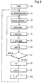
- FIG. 3 shows a flowchart of the control process for controlling the interior temperature in accordance with this exemplary embodiment of the present invention.
- the delay time T v of the process is first recorded in step S1 in order to enable optimal controller behavior even with changing loading.
- the cooling unit is suddenly switched on by controller 1, for example, with a step in the manipulated variable in order to work with a predetermined constant output for a certain time that is greater than the dead time T tot of the process.
- the slope of the curve of the interior temperature over time or an average slope over a predetermined period of time is detected and the delay time T v of this process is determined from this.
- step S2 the actual process of regulating the interior temperature begins.
- the deviation of the actual temperature value from the target value is recorded in this exemplary embodiment.
- the current change in the interior temperature is also recorded.
- controller 1 calculates a new manipulated variable from the setpoint deviation, from the change in interior temperature and from the value of the previous manipulated variable (step S3) and stores this newly calculated manipulated variable in step S4.
- This newly calculated manipulated variable is entered in the cooling process.
- the controller also calculates a waiting time T w during which no control process takes place, but rather the calculated manipulated variable is kept constant. This waiting time is calculated on the basis of the newly calculated, current manipulated variable and the previous manipulated variable.
- the controller extends the waiting time until the next manipulated variable is calculated and holds during the Waiting time (S6) the current manipulated variable Y unchanged.
- the process reaction is waited for a longer waiting time for large jumps in the manipulated variable or for large jumps in the setpoint value before a new manipulated variable calculation takes place, the behavior of the process can be incorporated into the control process with greater accuracy and overshoots can be avoided in this way.
- the controller can react quickly to disturbing influences by shorter waiting times with small manipulated variable changes and quickly correct such influences.
- the step S1 When calculating the waiting time in S5, the step S1 detected delay time and thus the loading of the Interior with refrigerated goods taken into account. The bigger the detected delay time, the larger the Waiting time until a new manipulated variable is calculated.
- step S7 checks how long the cooling process has lasted. Becomes found in step 7 that the cooling process is a certain one Has reached the end, the defrosting process becomes step S8 passed while otherwise the control process is continued with step S2.
- step S8 the power supplied to the cooling unit turned off and waited in step S9 to defrost ice, that has formed on the evaporator 9. Then in Step S10 causes a manipulated variable jump, similar to Process when switching on in S0. After that will again in S1 the delay time of the process new recorded and stored in order to calculate the Waiting time to be available in S5. In this way Even with a variation of the process parameters, i.e. with different loading of the refrigerator Adjusted controller behavior to be optimal.
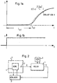
- FIG. 4 shows in the upper diagram a sequence of activity cycles with a duration T c which the controller requires in order to carry out the calculation of the new manipulated variable and the calculation of the waiting time T w during which the newly calculated manipulated variable is kept constant. This results in a course of the manipulated variable, as is shown in the lower diagram in FIG. 4. If the manipulated variable makes a jump that is greater than a predetermined threshold value, the waiting time is extended until a new manipulated variable is calculated. It has been shown that satisfactory controller behavior can already be achieved if the controller, depending on the size of the manipulated variable jump, chooses between two different waiting times, which are not dependent on the magnitude of the manipulated variable jump. The shorter waiting time is selected if the manipulated variable jump is below the predetermined threshold, while the longer waiting time is selected otherwise.
- the longer and the shorter waiting time are preferred depending on the delay time of the process, so depending on the load status of the refrigerator. The bigger the load is, the longer these waiting times are.
- the calculation time T c required to calculate the new manipulated variable and the waiting time, ie the duration of the activity phase, is negligibly short in this exemplary embodiment compared to the duration of the inactivity phase T i , so that the waiting time T w and the duration of the inactivity phase T i are almost the same.
- the size of the waiting time depends on the process to be controlled and is of the order of the dead time of the process.
- FIG. 5 shows a block diagram of a Embodiment of the controller according to the invention.
- the Controller comprises a manipulated variable calculator 1a, a timer 1b and a memory 1c.
- the change over time Setpoint deviation is determined using an analog or discrete differentiator 1e, such as one Microprocessor.
- the memory 1c stores the previous manipulated variable Y (n-1) before the manipulated variable calculator 1a outputs a new manipulated variable Y (n).
- the timer 1b is used to calculate the waiting time T w during which the manipulated variable Y (n) remains unchanged and controls the inactivity and activity phases of the manipulated variable computer 1a via the connection to the manipulated variable computer 1a.
- the timer receives the newly calculated manipulated variable Y (n) and the preceding manipulated variable Y (n-1) from the memory 1c.
- the timer also controls the defrosting process at regular intervals and detects the delay time T v of the process from the drop in the interior temperature at the beginning of the next cooling phase. Alternatively or additionally, the temperature profile of the interior temperature during the defrosting phase can be used to record the delay time. Finally, the timer controls the update of the memory 1c.
- the functions of the manipulated variable computer and the timer are preferably carried out by a single microprocessor, but can also be designed as separate units. Suitable analog / digital converters are connected upstream of the manipulated variable calculator to calculate the manipulated variable. Depending on the process, the manipulated variable Y is available as a pulse-width-modulated digital signal for power setting or as a numerical digital value that is entered into the process after being converted into an analog value.
- the calculation of the manipulated variable using the The manipulated variable calculator 1a is preferably accessed Map in a map memory provided for this purpose carried out.
- the manipulated variable calculator 1a Fuzzy logic for calculating the manipulated variable.
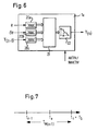
- Figure 6 shows the essential functional components of a Fuzzy logic based manipulated variable calculator 1a.
- the Input variables setpoint deviation e, change over time Setpoint deviation or change in time of the Interior temperature de and the previous manipulated variable Y are in fuzzification units 20a to 20c fuzzifies.
- a rule base 21 contains a set of Rules which linguistic terms of each Input variables with linguistic terms of the Link the calculated manipulated variable.
- Figure 7 shows the operation of an embodiment of the differentiating element 1e of Figure 5.
- the temporal change in the setpoint deviation e or the temporal change in the interior temperature is estimated by recording the interior temperature in succession at times t a and t b , and estimating the temporal Change from the difference between the temperature values recorded at these times.
- the time interval between t a and t b is chosen so that a compromise is made between the precision of the estimation of the change on the one hand and the resolution of small changes on the other.
- a preferred time interval between t a and t b is half the waiting time T w .
- the time t b can coincide with the end of the waiting time.
Landscapes
- Engineering & Computer Science (AREA)
- Artificial Intelligence (AREA)
- Physics & Mathematics (AREA)
- Software Systems (AREA)
- General Physics & Mathematics (AREA)
- Automation & Control Theory (AREA)
- Health & Medical Sciences (AREA)
- Computer Vision & Pattern Recognition (AREA)
- Evolutionary Computation (AREA)
- Medical Informatics (AREA)
- Fuzzy Systems (AREA)
- Mathematical Physics (AREA)
- Mechanical Engineering (AREA)
- Thermal Sciences (AREA)
- General Engineering & Computer Science (AREA)
- Feedback Control In General (AREA)
- Electrical Discharge Machining, Electrochemical Machining, And Combined Machining (AREA)
- Diaphragms For Electromechanical Transducers (AREA)
- Control By Computers (AREA)
- Control Of Temperature (AREA)
Description
- Figur 1
- ein Beispiel eines Ausgangsgrößenverlaufes bei einem Stellgrößensprung;
- Figur 2
- ein Ausführungsbeispiel der Erfindung anhand eines Absorberkühlschrankes;
- Figur 3
- ein Beispiel einer Abfolge von Aktivitäts- und Inaktivitätsphasen des Reglers und ein Beispiel eines Verlaufs der Stellgröße;
- Figur 4
- ein Flußdiagramm zur Erläuterung der Arbeitsphasen des Reglers dieses Ausführungsbeispiels;
- Figur 5
- ein Blockdiagramm eines Ausführungsbeispiels eines Reglers;
- Figur 6
- ein Ausführungsbeispiel einer Reglerkomponente unter Verwendung von Fuzzylogik; und
- Figur 7
- ein Ausführungsbeispiel der Funktion des Differenziergliedes der Figur 5.
Claims (25)
- Verfahren zum Regeln einer Ausgangsgröße eines Prozesses mit den Schritten:dadurch gekennzeichnet, daßErfassen eines Abtastwertes der Ausgangsgröße (X);Vergleichen (S2) des Abtastwertes der Ausgangsgröße (X) mit einem Sollwert (w) und Ermitteln einer Sollwertabweichung (e);Berechnen (S3) eines Wertes einer Stellgröße (Y) abhängig von der ermittelten Sollwertabweichung (e) derart, dass die Ausgangsgröße (X) des Prozesses an den Sollwert (w) herangeführt wird, und Eingeben der Stellgröße (Y) in den Prozess;Berechnen einer variablen Watezeit (Tw) und nach Verstreichen (S6) der Wartezeit (Tw) erneutes Bestimmen (S3) eines Wertes der Stellgröße (Y);wobei während der Wartezeit (Tw) die Stellgröße nicht geändert wird,die Wartezeit (Tw) auf der Grundlage der Differenz zwischen dem Wert der Stellgröße (Y) und einem früheren Wert der Stellgröße (Y), die auf der Grundlage eines früheren Abtastwertes berechnet wurde, berechnet wird (S5).
- Verfahren nach Anspruch 1,
dadurch gekennzeichnet, daß die Abhängigkeit der Wartezeit (Tw) vom Betrag der Differenz ein monoton steigendes Verhalten aufweist. - Verfahren nach Anspruch 2,
dadurch gekennzeichnet, daß die Wartezeit (Tw) eine erste vorgegebene Zeitdauer (Tw1) beträgt, wenn der Betrag der Differenz zwischen berechnetem und früherem Stellgrößenwert (Y) kleiner als ein vorgegebener Wert ist, und andernfalls die Wartezeit (Tw) eine zweite vorgegebene Zeitdauer (Tw2) beträgt, die größer als die erste Zeitdauer ist. - Verfahren nach Anspruch 3,
dadurch gekennzeichnet, daß die zweite vorgegebene Zeitdauer um mehr als 25% größer als die erste vorgegebene Zeitdauer ist. - Verfahren nach einem der vorangehenden Ansprüche,
gekennzeichnet durchErfassen (S1) einer Verzögerungszeit (Tv) und/oder Totzeit (Ttot) des Prozesses; undBerechnen (S5) der Wartezeit auf der Grundlage der erfaßten Verzögerungszeit und/oder Totzeit. - Verfahren nach Anspruch 3, 4 oder 5,
dadurch gekennzeichnet, daß die erste vorgegebene Zeitdauer (Tw1) größer oder gleich einer Totzeit (Ttot) des Prozesses ist. - Verfahren nach Anspruch 5,
dadurch gekennzeichnet, daß die Verzögerungszeit (Tv) des Prozesses erfaßt wird mit den SchrittenBeaufschlagen des Prozesses mit einem Stellgrößensprung (S10);nach Verstreichen einer vorbestimmten Erfassungszeitdauer Erfassen (S1) des zeitlichen Verlaufs der Ausgangsgröße (X). - Verfahren nach Anspruch 5,
dadurch gekennzeichnet, daß die Totzeit (Ttot) des Prozesses erfaßt wird mit den SchrittenBeaufschlagen des Prozesses mit einem Stellgrößensprung; undErfassen einer Zeitdauer beginnend mit dem Zeitpunkt (to) des Stellgrößensprunges bis zu dem Zeitpunkt Ttot, in welchem die Änderung der Ausgangsgröße (X) eine vorbestimmte Schwelle überschreitet. - Verfahren nach einem der Ansprüche 5 bis 8,
dadurch gekennzeichnet, daß die Verzögerungszeit (Tv) und/oder Totzeit (Ttot) regelmäßig wiederkehrend erfaßt werden (S7). - Verfahren nach einem der vorangehenden Ansprüche,
dadurch gekennzeichnet, daß die Berechnung der Stellgröße (Y) die weiteren Schritte umfaßt:Erfassen (S2) der zeitlichen Änderung der Ausgangsgröße (X);Berechnen der Stellgröße (Y) auf der Grundlage der Ausgangsgröße (X), der zeitlichen Änderung der Ausgangsgröße (X) und der früheren Stellgröße (Y) . - Verfahren nach Anspruch 10,
dadurch gekennzeichnet, daß die zeitliche Änderung der Ausgangsgröße aus der Differenz zweier aufeinanderfolgender Abtastwerte (X(n),X(n-1)) der Ausgangsgröße (X) berechnet wird. - Verfahren nach Anspruch 11,
dadurch gekennzeichnet, daß der zeitliche Abstand zwischen den zwei aufeinanderfolgenden Abtastwerten der Ausgangsgröße die Hälfte der Wartezeit (Tw(n)) ist. - Verfahren nach einem der vorangehenden Ansprüche,
dadurch gekennzeichnet, daß die Stellgröße (Y) während der Wartezeit (Tw) konstant ist. - Verfahren nach einem der vorangehenden Ansprüche,
dadurch gekennzeichnet, daß die Wartezeit (Tw(n)) und/oder die Stellgröße (Y(n)) aus einem Kennfeld ausgelesen werden. - Verfahren nach einem der Ansprüche 1 bis 13,
dadurch gekennzeichnet, daß die Stellgröße (Y) und/oder die Wartezeit (Tw) mittels Fuzzylogik berechnet wird, mit den SchrittenDefinieren von linguistischen Termen jeweils für die als Grundlage für die Berechnung der Stellgröße bzw. Wartezeit dienenden Größen (e, de) sowie für die Stellgröße (Y) bzw. Wartezeit (Tw)Definieren von Mitgliedschaftsfunktionen für jeden der linguistischen Terme;für jede Größe Ermitteln der Mitgliedschaftswerte zu jedem betreffenden Term,Eingeben der Mitgliedschaftswerte in eine Regelbasis (21), welche die linguistischen Terme der Eingangsgrößen mit den linguistischen Termen der Stellgröße (Y) bzw. Wartezeit (Tw) verknüpft, und Berechnen einer Mitgliedschaftsfunktion für die Stellgröße (Y) bzw. Wartezeit (Tw); undDefuzzifizieren der Stellgröße bzw. Wartezeit auf der Grundlage von deren Mitgliedschaftsfunktion. - Verfahren nach einem der vorangehenden Ansprüche, dadurch gekennzeichnet, daß die Stellgröße (Y) die einem Kocher des Absorptionskühlaggregates (2) in einem Kühlschrank (2,3,4) zugeführte Antriebsleistung ist, die Ausgangsgröße (X) die Innenraumtemperatur des Kühlraumes (3) ist, und der Sollwert (w) eine voreinstellbare Vorgabe der Innenraumtemperatur ist.
- Verfahren nach Anspruch 16 soweit abhängig von Anspruch 9,
dadurch gekennzeichnet, daß die Erfassung von Totzeit (Ttot) und/oder Verzögerungszeit (Tv) nach einem Abtauvorgang durchgeführt wird. - Regler zur Durchführung des Verfahrens nach einem der vorangehenden Ansprüche, mitgekennzeichnet durch:einer Einrichtung (5) zur Erfassung der Ausgangsgröße (X) des Prozesses;einer Einstelleinrichtung (6) zum Voreinstellen des Sollwertes (w) ;einem Mikroprozessor mit Arbeits- und Programmspeicher, zum Empfangen einer Sollwertabweichung (e) und zum Berechnen und Ausgeben eines aktuellen Wertes für die Stellgröße (Y),einer Einrichtung zur Eingabe der Stellgröße in den Prozeß;einem Zeitgeber (1b), welcher ausgebildet ist, eine variable Wartezeit (Tw) zu berechnen, während welcher die Stellgröße nicht geändert wird;einen Speicher (lc) für eine früher berechnete Stellgröße (Y);wobei der Zeitgeber (1b) ausgebildet ist, den früher berechneten Wert der Stellgröße und den aktuellen Wert der Stellgröße zu empfangen, abhängig von deren Differenz die Wartezeit (Tw) zu berechnen, und nach Verstreichen dieser Wartezeit eine erneute Berechnung eines Wertes für die Stellgröße (Y) durch den Mikroprozessor auszulösen.
- Regler nach Anspruch 18,
gekennzeichnet durch eine Einrichtung zum Berechnen der Differenz zwischen der gespeicherten, früher berechneten Stellgröße (Y) und dem aktuell berechneten Wert der Stellgröße (Y); wobei der Zeitgeber (1b) ausgebildet ist, abhängig von dieser Differenz die Wartezeit (Tw(n)) zu berechnen. - Regler nach Anspruch 19,
dadurch gekennzeichnet, daß der Zeitgeber (1b) ausgebildet ist, eine erste Wartezeit (Tw1) vorzugeben, wenn der Betrag der Differenz zwischen dem früheren und dem aktuellen Wert der Stellgröße kleiner ist als ein vorbestimmter Wert, und eine zweite größere Wartezeit (Tw2) vorzugeben, wenn der Betrag dieser Differenz größer als der Schwellwert ist. - Regler nach Anspruch 18, 19 oder 20,
dadurch gekennzeichnet, daß der Zeitgeber (1b) ausgebildet ist, die Wartezeit (Tw) abhängig von einer Totzeit (Ttot) und/oder Verzögerungszeit (Tv) des Prozesses zu berechnen. - Regler nach einem der Ansprüche 18 bis 21,
dadurch gekennzeichnet, daßdie Einrichtung zur Erfassung der Ausgangsgröße (y) des Prozesses einen Lufttemperatursensor (5) und einen Analog/Digital-Wandler einschließt, unddie Einrichtung zur Eingabe der Stellgröße in den Prozess ein Stellglied zum Einstellen von dem Prozess zuzuführender Leistung umfaßt. - Regler nach einem der Ansprüche 18 bis 22,
gekennzeichnet durcheine Einrichtung (1d) zum Erfassen der zeitlichen Änderung der Ausgangsgröße und Eingeben des erfaßten Änderungswertes in den Mikroprozessor. - Regler nach einem der Ansprüche 18 bis 22,
dadurch gekennzeichnet, daß zur Berechnung der Stellgröße (Y) und/oder der Wartezeit (Tw) ein Kennfeldspeicher vorgesehen ist. - Regler nach Anspruch 23,
gekennzeichnet, durchEinrichtungen (20a) zum Fuzzifizieren einer Abweichung der Ausgangsgröße (X) vom voreingestellten Sollwert (w),Einrichtungen (20b) zum Fuzzifizieren des erfaßten Änderungswertes (de);Einrichtungen (20c) zum Fuzzifizieren der früher berechneten Stellgröße;Einrichtungen (21) zum Speichern von fuzzylogischen Regeln zur Verwendung durch den Mikroprozessor; undEinrichtungen (22) zum Defuzzifizieren einer von dem Mikroprozessor ausgegebenen Fuzzymenge der Ausgangsgröße (X).
Applications Claiming Priority (2)
| Application Number | Priority Date | Filing Date | Title |
|---|---|---|---|
| DE19516627 | 1995-05-05 | ||
| DE19516627A DE19516627A1 (de) | 1995-05-05 | 1995-05-05 | Verfahren und Vorrichtung zur Regelung eines Prozesses |
Publications (2)
| Publication Number | Publication Date |
|---|---|
| EP0741345A1 EP0741345A1 (de) | 1996-11-06 |
| EP0741345B1 true EP0741345B1 (de) | 2002-03-06 |
Family
ID=7761231
Family Applications (1)
| Application Number | Title | Priority Date | Filing Date |
|---|---|---|---|
| EP96106969A Expired - Lifetime EP0741345B1 (de) | 1995-05-05 | 1996-05-03 | Verfahren und Vorrichtung zur Regelung eines Prozesses |
Country Status (6)
| Country | Link |
|---|---|
| US (1) | US5726880A (de) |
| EP (1) | EP0741345B1 (de) |
| AT (1) | ATE214168T1 (de) |
| CA (1) | CA2175739C (de) |
| DE (2) | DE19516627A1 (de) |
| DK (1) | DK0741345T3 (de) |
Families Citing this family (19)
| Publication number | Priority date | Publication date | Assignee | Title |
|---|---|---|---|---|
| DE19603091C1 (de) * | 1996-01-29 | 1997-07-31 | Siemens Ag | Verfahren zur Regelung einer Regelstrecke, insbesondere einer Brennkraftmaschine |
| DE19642745C2 (de) * | 1996-10-16 | 2000-09-14 | Electrolux Siegen Gmbh | Absorberkühlschrank |
| JP3626066B2 (ja) * | 2000-03-29 | 2005-03-02 | 株式会社 沖マイクロデザイン | 計算装置及び計算方法 |
| DE10104109A1 (de) * | 2001-01-31 | 2002-09-05 | Mannesmann Rexroth Ag | Regelverfahren für die hydraulische Unterstützung eines elektrischen Antriebs |
| US7495561B2 (en) * | 2006-08-25 | 2009-02-24 | International Business Machines Corporation | Item position indicator and optimized item retrieval for a sensor equipped storage unit |
| US8226414B2 (en) * | 2006-08-25 | 2012-07-24 | International Business Machines Corporation | Generating policy driven meal plans |
| US7937289B2 (en) * | 2006-08-25 | 2011-05-03 | International Business Machines Corporation | Method and apparatus for monitoring unit depletion in an independent real-time mass storage unit system by using an estimated tare mass of the item |
| US7673464B2 (en) * | 2006-08-25 | 2010-03-09 | International Business Machines Corporation | Method and apparatus for temperature based placement of an item within a storage unit |
| US8032430B2 (en) | 2006-08-25 | 2011-10-04 | International Business Machines Corporation | Method and apparatus for mapping content descriptions to reusable containers |
| US7844509B2 (en) * | 2006-08-25 | 2010-11-30 | International Business Machines Corporation | Method and apparatus for monitoring depletion of an item |
| US20080052201A1 (en) * | 2006-08-25 | 2008-02-28 | William Kress Bodin | Method and apparatus for tracking usage of an item within a storage unit using location sensors |
| US7840500B2 (en) * | 2006-11-30 | 2010-11-23 | Corning Incorporated | Fuzzy logic control for process with large dead time |
| JP4286880B2 (ja) * | 2007-04-25 | 2009-07-01 | 本田技研工業株式会社 | 制御パラメータを探索するためのプログラム |
| JP5069503B2 (ja) * | 2007-06-26 | 2012-11-07 | 三菱重工プラスチックテクノロジー株式会社 | 射出成形システム、コンピュータプログラム、射出成形方法、射出成形機 |
| US10430843B2 (en) * | 2009-06-01 | 2019-10-01 | Additech, Inc. | Method and system for purchasing non-fuel merchandise |
| DE102011084352B4 (de) * | 2011-10-12 | 2022-12-29 | Robert Bosch Gmbh | Verfahren und Steuergerät zum Betreiben eines Leitungskreises zur Abwärmenutzung einer Brennkraftmaschine |
| DE102011116819B4 (de) | 2011-10-25 | 2022-05-25 | Festo Se & Co. Kg | Verfahren zum Ansteuern eines elektrisch betreibbaren Stellmittels für ein Fluidsteuerventil und Ventileinrichtung |
| US9621088B2 (en) | 2014-02-27 | 2017-04-11 | General Electric Company | System and method for reducing ice and/or condensation formed on a power component |
| CN114114895B (zh) * | 2021-12-22 | 2024-01-30 | 北京国控天成科技有限公司 | 应用于石油化工领域的自动控制方法和系统 |
Family Cites Families (49)
| Publication number | Priority date | Publication date | Assignee | Title |
|---|---|---|---|---|
| DE2257406A1 (de) * | 1972-11-23 | 1974-06-12 | Philips Patentverwaltung | Verfahren und anordnung zur konstanthaltung der dosiermenge bei kunststoffverarbeitenden spritzgiessmaschinen |
| JPS5417393B2 (de) * | 1973-04-25 | 1979-06-29 | ||
| GB2004089B (en) * | 1977-07-16 | 1982-01-13 | Rolls Royce | Control system |
| SE442921B (sv) * | 1978-02-23 | 1986-02-03 | Asea Ab | Sjelvinstellande regulator |
| DD137419A1 (de) * | 1978-06-26 | 1979-09-05 | Manfred Kunert | Einrichtung zum steuern des anhaltens der werkstueckbewegung |
| US4386397A (en) * | 1979-12-18 | 1983-05-31 | Honeywell Inc. | Method and apparatus for process control |
| GB2068596A (en) * | 1980-01-24 | 1981-08-12 | Plessey Co Ltd | Parameter controller |
| DE3134180C2 (de) * | 1981-08-28 | 1983-11-24 | Waeschle Maschinenfabrik Gmbh, 7980 Ravensburg | Verfahren zur Dosierung von pneumatisch transportiertem Schüttgut |
| US4481567A (en) * | 1982-03-01 | 1984-11-06 | The Babcock & Wilcox Company | Adaptive process control using function blocks |
| FR2524621B1 (fr) * | 1982-04-06 | 1986-05-09 | Bonnet Ets | Procede et dispositif de refrigeration par adsorption |
| US4522333A (en) * | 1983-09-16 | 1985-06-11 | Fluidmaster, Inc. | Scheduled hot water heating based on automatically periodically adjusted historical data |
| JPS61235119A (ja) * | 1985-04-12 | 1986-10-20 | Nissei Plastics Ind Co | 射出成形機の射出制御方法及び装置 |
| DE3535787A1 (de) * | 1985-10-07 | 1987-04-09 | Siemens Ag | Verfahren zur bestimmung von regelstreckenparametern |
| DE3538516A1 (de) * | 1985-10-30 | 1987-05-07 | Philips Patentverwaltung | Gewichtsregler fuer eine regelbare spritzgiessmaschine |
| CH668740A5 (de) * | 1985-11-29 | 1989-01-31 | Netstal Ag Maschf Giesserei | Verfahren und einrichtung zum messen und regeln der schliesskraft einer kunststoff-spritzgiessmaschine. |
| US4620667A (en) * | 1986-02-10 | 1986-11-04 | Fluidmaster, Inc. | Hot water heating system having minimum hot water use based on minimum water temperatures and time of heating |
| DE3717555A1 (de) * | 1987-05-25 | 1988-12-08 | Siemens Ag | Verfahren zum bestimmen der parameter eines verzoegerungsgliedes n-ter ordnung mit gleichen zeitkonstanten |
| DE3721504C2 (de) * | 1987-06-30 | 1997-01-23 | Bosch Gmbh Robert | Regelsystem |
| DE3733396C2 (de) * | 1987-10-02 | 1998-12-17 | Rexroth Mannesmann Gmbh | Elektrische Pumpenregelung für die Förderstrom- und Druckregelung an einem Verbraucher |
| DE3743892C1 (de) * | 1987-12-21 | 1988-12-15 | Ekkehard Dipl-Inform Kress | Regler |
| JPH02132502A (ja) * | 1988-07-28 | 1990-05-22 | Omron Tateisi Electron Co | ファジィ制御装置における動作方法および調整装置 |
| JP2553675B2 (ja) * | 1988-11-18 | 1996-11-13 | 日本電気硝子株式会社 | プロセスの制御方法 |
| DE3921329A1 (de) * | 1989-06-29 | 1991-01-03 | Vdo Schindling | Verfahren und vorrichtung zur feststellung einer fehlfunktion einer einen stromregelkreis aufweisenden endstufe in einer leerlaufdrehzahlregelungsanordnung einer brennkraftmaschine |
| US5270916A (en) * | 1990-02-27 | 1993-12-14 | Ge Fanuc Automation North America, Inc. | Apparatus and method for preventing runaway of the integral term of a proportional plus integral controller |
| DE4012577C1 (de) * | 1990-04-20 | 1991-04-18 | Robert Bosch Gmbh, 7000 Stuttgart, De | |
| US5156013A (en) * | 1990-05-29 | 1992-10-20 | Sanyo Electric Co., Ltd. | Control device for absorption refrigerator |
| EP0460892B1 (de) * | 1990-06-04 | 1996-09-04 | Hitachi, Ltd. | Steuerungsvorrichtung für die Steuerung einer gesteuerten Anlage und Steuerungsverfahren dafür |
| JPH04105915A (ja) * | 1990-08-27 | 1992-04-07 | Nissei Plastics Ind Co | 射出成形機の温度制御方法 |
| JP3138004B2 (ja) * | 1991-05-17 | 2001-02-26 | 三洋電機株式会社 | 吸収式冷凍機の制御装置 |
| US5566275A (en) * | 1991-08-14 | 1996-10-15 | Kabushiki Kaisha Toshiba | Control method and apparatus using two neural networks |
| DE4131765A1 (de) * | 1991-09-24 | 1993-03-25 | Siemens Ag | Regelparameter-verbesserungsverfahren fuer industrielle anlagen |
| AT400201B (de) * | 1991-11-11 | 1995-11-27 | Vaillant Gmbh | Verfahren zum betreiben einer regeleinrichtung und vorrichtung zu seiner durchführung |
| JPH05313705A (ja) * | 1992-05-12 | 1993-11-26 | Hitachi Ltd | プロセス制御方法および装置 |
| US5371832A (en) * | 1992-06-12 | 1994-12-06 | Siemens Aktiengesellschaft | Fuzzy logic controller having high processing speed |
| JPH05346281A (ja) * | 1992-06-15 | 1993-12-27 | Nec Home Electron Ltd | 冷蔵庫 |
| US5371450A (en) * | 1992-08-10 | 1994-12-06 | Sumitomo Heavy Industries, Ltd. | Control unit capable of smoothly carrying out a switching operation between position and pressure feedback control systems |
| DE4226383C2 (de) * | 1992-08-10 | 1999-05-20 | Stuhl Regelsysteme Gmbh | Meß- und Regelverfahren für ein elektronisches Zwei-Punkt- oder Proportional-Regelgerät |
| US5477444A (en) * | 1992-09-14 | 1995-12-19 | Bhat; Naveen V. | Control system using an adaptive neural network for target and path optimization for a multivariable, nonlinear process |
| DE4232826C1 (de) * | 1992-09-30 | 1993-10-28 | Siemens Ag | Verfahren und Vorrichtung zur Messung der Totzeit einer Regelgröße und ihre Verwendung |
| DE4232752C1 (de) * | 1992-09-30 | 1994-06-09 | Zetec Gmbh | Verfahren zur Erzeugung einer scharfen Ausgangsstellgröße am Ausgang eines Fuzzy-Regelkreises |
| ATE162895T1 (de) * | 1992-10-01 | 1998-02-15 | Siemens Ag | Vorrichtung zur automatischen führung einer verfahrenstechnischen anlage durch fuzzy- steuerung des prozessführungsraumes, mit bevorzugten verwendungen |
| DE4237857C2 (de) * | 1992-11-10 | 1994-12-15 | Daimler Benz Ag | Verfahren zur zeitlich getakteten Ermittlung von Stellgrößen nach einer Fuzzy-Logik |
| DE4240788A1 (de) * | 1992-12-04 | 1994-06-09 | Bodenseewerk Geraetetech | Regler |
| US5336073A (en) * | 1992-12-16 | 1994-08-09 | Sumitomo Heavy Industries, Ltd. | Injection pressure limiting device for injection molding machine |
| DE4308541A1 (de) * | 1993-03-17 | 1994-09-22 | Bosch Gmbh Robert | Verfahren und Vorrichtung zur Steuerung und/oder Regelung eines Stellgliedes |
| DE4416364B4 (de) * | 1993-05-17 | 2004-10-28 | Siemens Ag | Verfahren und Regeleinrichtung zur Regelung eines Prozesses |
| US5420785A (en) * | 1993-05-26 | 1995-05-30 | The Foxboro Company | Self-tuning deadtime process controller |
| DE4331142C2 (de) * | 1993-09-14 | 1995-07-06 | Daimler Benz Ag | Verfahren zur Regelung der Temperatur eines Innenraums, insbesondere für ein Kraftfahrzeug |
| DE59404777D1 (de) * | 1994-01-17 | 1998-01-22 | Siemens Ag | Verfahren und Vorrichtung zur Führung eines Prozesses |
-
1995
- 1995-05-05 DE DE19516627A patent/DE19516627A1/de not_active Withdrawn
-
1996
- 1996-05-03 DK DK96106969T patent/DK0741345T3/da active
- 1996-05-03 EP EP96106969A patent/EP0741345B1/de not_active Expired - Lifetime
- 1996-05-03 US US08/642,403 patent/US5726880A/en not_active Expired - Lifetime
- 1996-05-03 CA CA002175739A patent/CA2175739C/en not_active Expired - Fee Related
- 1996-05-03 AT AT96106969T patent/ATE214168T1/de not_active IP Right Cessation
- 1996-05-03 DE DE59608818T patent/DE59608818D1/de not_active Expired - Fee Related
Also Published As
| Publication number | Publication date |
|---|---|
| DE59608818D1 (de) | 2002-04-11 |
| CA2175739A1 (en) | 1996-11-06 |
| US5726880A (en) | 1998-03-10 |
| CA2175739C (en) | 2005-10-25 |
| DK0741345T3 (da) | 2002-05-27 |
| EP0741345A1 (de) | 1996-11-06 |
| ATE214168T1 (de) | 2002-03-15 |
| DE19516627A1 (de) | 1996-11-07 |
Similar Documents
| Publication | Publication Date | Title |
|---|---|---|
| EP0741345B1 (de) | Verfahren und Vorrichtung zur Regelung eines Prozesses | |
| DE3843060C2 (de) | Elektronische Drosselklappensteuervorrichtung und Steuerverfahren für eine elektrisch betriebene Drosselklappe | |
| EP1800065B1 (de) | Verfahren zur steuerung eines garvorgangs bei einem gargerät | |
| DE19756053B4 (de) | Drosselklappensteuervorrichtung | |
| DE2715408C2 (de) | Verfahren zum Betrieb und Regeleinrichtung für eine Brennkraftmaschine zum Konstanthalten wählbarer Drehzahlen | |
| DE3237816C2 (de) | ||
| DE4404668A1 (de) | Verfahren und Vorrichtung zur Steuerung der Leistung einer Brennkraftmaschine | |
| DE3317941C2 (de) | Temperaturregelvorrichtung | |
| EP0935181A2 (de) | Selbstlernendes Regelverfahren und selbstlernendes Regelsystem zur Regelung einer Temperiereinrichtung | |
| DE4210090C2 (de) | Abtausteuerung für einen Kühlschrank | |
| DE19722431A1 (de) | Verfahren zur Regelung eines verzögerungsbehafteten Prozesses mit Ausgleich sowie Regeleinrichtung zur Durchführung des Verfahrens | |
| DE10260260A1 (de) | Maschinenkühlsystem | |
| WO1997024648A1 (de) | Verfahren zur regelung eines verzögerungsbehafteten prozesses mit ausgleich sowie regeleinrichtung zur durchführung des verfahrens | |
| DE19610210B4 (de) | Verfahren zur Lageregelung eines Stellelements einer Brennkraftmaschine | |
| DE60129231T2 (de) | Verfahren zur Regelung eines Kompressors mit variabler Kühlleistung und nach diesem Verfahren geregelter Kühl- oder Gefrierschrank | |
| DE19945396B4 (de) | Brennkraftmaschinen-Steuervorrichtung mit Interpolationssteuereinrichtung | |
| DE4420122B4 (de) | Verfahren und Vorrichtung zur Bestimmung einer Endstellung einer Verstelleinrichtung in Fahrzeugen | |
| DE3325993C2 (de) | Regeleinrichtung zum Regeln der Temperatur eines zu Heizkörpern vorlaufenden Wärmeträgers | |
| DE69415140T2 (de) | STEUERSYSTEM FüR EIN HOCHDRUCK-KRAFTSTOFFEINSPRITZSYSTEM FüR EINE BRENNKRAFTMASCHINE | |
| DE3610962C1 (de) | Verfahren zum Regeln der Innenraumtemperatur,insbesondere eines Kraftfahrzeugs | |
| DE3703000C2 (de) | Anordnung zum Steuern einer Gebäudeheizung oder -kühlung | |
| DE19549224A1 (de) | Verfahren und Vorrichtung zur Regelung bzw. Begrenzung der Geschwindigkeit eines Fahrzeugs | |
| DE19601232C2 (de) | Steller für einen Regelkreis | |
| DE4408425A1 (de) | Verfahren und Vorrichtung zum Einregeln der Winkellage einer Nockenwelle | |
| EP0381858B1 (de) | Einrichtung zur Regelung der Ansauggemischtemperatur einer Brennkraftmaschine, insbesondere in Kraftfahrzeugen |
Legal Events
| Date | Code | Title | Description |
|---|---|---|---|
| PUAI | Public reference made under article 153(3) epc to a published international application that has entered the european phase |
Free format text: ORIGINAL CODE: 0009012 |
|
| AK | Designated contracting states |
Kind code of ref document: A1 Designated state(s): AT BE CH DE DK ES FI FR GB GR IE IT LI LU MC NL PT SE |
|
| RAP1 | Party data changed (applicant data changed or rights of an application transferred) |
Owner name: RANCO INCORPORATED OF DELAWARE |
|
| 17P | Request for examination filed |
Effective date: 19970320 |
|
| 17Q | First examination report despatched |
Effective date: 20000427 |
|
| GRAG | Despatch of communication of intention to grant |
Free format text: ORIGINAL CODE: EPIDOS AGRA |
|
| GRAG | Despatch of communication of intention to grant |
Free format text: ORIGINAL CODE: EPIDOS AGRA |
|
| GRAH | Despatch of communication of intention to grant a patent |
Free format text: ORIGINAL CODE: EPIDOS IGRA |
|
| GRAH | Despatch of communication of intention to grant a patent |
Free format text: ORIGINAL CODE: EPIDOS IGRA |
|
| REG | Reference to a national code |
Ref country code: GB Ref legal event code: IF02 |
|
| GRAA | (expected) grant |
Free format text: ORIGINAL CODE: 0009210 |
|
| AK | Designated contracting states |
Kind code of ref document: B1 Designated state(s): AT BE CH DE DK ES FI FR GB GR IE IT LI LU MC NL PT SE |
|
| PG25 | Lapsed in a contracting state [announced via postgrant information from national office to epo] |
Ref country code: NL Free format text: LAPSE BECAUSE OF FAILURE TO SUBMIT A TRANSLATION OF THE DESCRIPTION OR TO PAY THE FEE WITHIN THE PRESCRIBED TIME-LIMIT Effective date: 20020306 Ref country code: IE Free format text: LAPSE BECAUSE OF FAILURE TO SUBMIT A TRANSLATION OF THE DESCRIPTION OR TO PAY THE FEE WITHIN THE PRESCRIBED TIME-LIMIT Effective date: 20020306 Ref country code: GR Free format text: LAPSE BECAUSE OF FAILURE TO SUBMIT A TRANSLATION OF THE DESCRIPTION OR TO PAY THE FEE WITHIN THE PRESCRIBED TIME-LIMIT Effective date: 20020306 Ref country code: FI Free format text: LAPSE BECAUSE OF FAILURE TO SUBMIT A TRANSLATION OF THE DESCRIPTION OR TO PAY THE FEE WITHIN THE PRESCRIBED TIME-LIMIT Effective date: 20020306 |
|
| REF | Corresponds to: |
Ref document number: 214168 Country of ref document: AT Date of ref document: 20020315 Kind code of ref document: T |
|
| REG | Reference to a national code |
Ref country code: CH Ref legal event code: EP |
|
| REF | Corresponds to: |
Ref document number: 59608818 Country of ref document: DE Date of ref document: 20020411 |
|
| PG25 | Lapsed in a contracting state [announced via postgrant information from national office to epo] |
Ref country code: MC Free format text: LAPSE BECAUSE OF NON-PAYMENT OF DUE FEES Effective date: 20020503 Ref country code: LU Free format text: LAPSE BECAUSE OF NON-PAYMENT OF DUE FEES Effective date: 20020503 Ref country code: AT Free format text: LAPSE BECAUSE OF NON-PAYMENT OF DUE FEES Effective date: 20020503 |
|
| REG | Reference to a national code |
Ref country code: DK Ref legal event code: T3 |
|
| PG25 | Lapsed in a contracting state [announced via postgrant information from national office to epo] |
Ref country code: LI Free format text: LAPSE BECAUSE OF NON-PAYMENT OF DUE FEES Effective date: 20020531 Ref country code: CH Free format text: LAPSE BECAUSE OF NON-PAYMENT OF DUE FEES Effective date: 20020531 Ref country code: BE Free format text: LAPSE BECAUSE OF NON-PAYMENT OF DUE FEES Effective date: 20020531 |
|
| PG25 | Lapsed in a contracting state [announced via postgrant information from national office to epo] |
Ref country code: SE Free format text: LAPSE BECAUSE OF FAILURE TO SUBMIT A TRANSLATION OF THE DESCRIPTION OR TO PAY THE FEE WITHIN THE PRESCRIBED TIME-LIMIT Effective date: 20020606 Ref country code: PT Free format text: LAPSE BECAUSE OF FAILURE TO SUBMIT A TRANSLATION OF THE DESCRIPTION OR TO PAY THE FEE WITHIN THE PRESCRIBED TIME-LIMIT Effective date: 20020606 |
|
| GBT | Gb: translation of ep patent filed (gb section 77(6)(a)/1977) |
Effective date: 20020516 |
|
| NLV1 | Nl: lapsed or annulled due to failure to fulfill the requirements of art. 29p and 29m of the patents act | ||
| ET | Fr: translation filed | ||
| PG25 | Lapsed in a contracting state [announced via postgrant information from national office to epo] |
Ref country code: ES Free format text: LAPSE BECAUSE OF FAILURE TO SUBMIT A TRANSLATION OF THE DESCRIPTION OR TO PAY THE FEE WITHIN THE PRESCRIBED TIME-LIMIT Effective date: 20020925 |
|
| REG | Reference to a national code |
Ref country code: IE Ref legal event code: FD4D |
|
| PG25 | Lapsed in a contracting state [announced via postgrant information from national office to epo] |
Ref country code: DE Free format text: LAPSE BECAUSE OF NON-PAYMENT OF DUE FEES Effective date: 20021203 |
|
| PLBE | No opposition filed within time limit |
Free format text: ORIGINAL CODE: 0009261 |
|
| STAA | Information on the status of an ep patent application or granted ep patent |
Free format text: STATUS: NO OPPOSITION FILED WITHIN TIME LIMIT |
|
| REG | Reference to a national code |
Ref country code: CH Ref legal event code: PL |
|
| 26N | No opposition filed |
Effective date: 20021209 |
|
| REG | Reference to a national code |
Ref country code: GB Ref legal event code: 732E |
|
| REG | Reference to a national code |
Ref country code: FR Ref legal event code: GC |
|
| PGFP | Annual fee paid to national office [announced via postgrant information from national office to epo] |
Ref country code: DK Payment date: 20070419 Year of fee payment: 12 |
|
| PGFP | Annual fee paid to national office [announced via postgrant information from national office to epo] |
Ref country code: GB Payment date: 20070410 Year of fee payment: 12 |
|
| PGFP | Annual fee paid to national office [announced via postgrant information from national office to epo] |
Ref country code: IT Payment date: 20070519 Year of fee payment: 12 |
|
| PGFP | Annual fee paid to national office [announced via postgrant information from national office to epo] |
Ref country code: FR Payment date: 20070503 Year of fee payment: 12 |
|
| REG | Reference to a national code |
Ref country code: DK Ref legal event code: EBP |
|
| GBPC | Gb: european patent ceased through non-payment of renewal fee |
Effective date: 20080503 |
|
| REG | Reference to a national code |
Ref country code: FR Ref legal event code: ST Effective date: 20090119 |
|
| PG25 | Lapsed in a contracting state [announced via postgrant information from national office to epo] |
Ref country code: FR Free format text: LAPSE BECAUSE OF NON-PAYMENT OF DUE FEES Effective date: 20080602 Ref country code: DK Free format text: LAPSE BECAUSE OF NON-PAYMENT OF DUE FEES Effective date: 20080531 |
|
| PG25 | Lapsed in a contracting state [announced via postgrant information from national office to epo] |
Ref country code: GB Free format text: LAPSE BECAUSE OF NON-PAYMENT OF DUE FEES Effective date: 20080503 |
|
| PG25 | Lapsed in a contracting state [announced via postgrant information from national office to epo] |
Ref country code: IT Free format text: LAPSE BECAUSE OF NON-PAYMENT OF DUE FEES Effective date: 20080503 |