EP0738605A2 - Flüssigkeitsbehälter für negativen Druck, Herstellungsverfahren, Tintenstrahlkassette mit dem Flüssigkeitsbehälter und einem Tintenstrahl-Aufzeichnungskopf als Einheit und Tintenstrahl-Aufzeichnungsgerät - Google Patents
Flüssigkeitsbehälter für negativen Druck, Herstellungsverfahren, Tintenstrahlkassette mit dem Flüssigkeitsbehälter und einem Tintenstrahl-Aufzeichnungskopf als Einheit und Tintenstrahl-Aufzeichnungsgerät Download PDFInfo
- Publication number
- EP0738605A2 EP0738605A2 EP96105946A EP96105946A EP0738605A2 EP 0738605 A2 EP0738605 A2 EP 0738605A2 EP 96105946 A EP96105946 A EP 96105946A EP 96105946 A EP96105946 A EP 96105946A EP 0738605 A2 EP0738605 A2 EP 0738605A2
- Authority
- EP
- European Patent Office
- Prior art keywords
- wall
- ink
- corner
- container
- liquid
- Prior art date
- Legal status (The legal status is an assumption and is not a legal conclusion. Google has not performed a legal analysis and makes no representation as to the accuracy of the status listed.)
- Granted
Links
Images


Classifications
-
- B—PERFORMING OPERATIONS; TRANSPORTING
- B41—PRINTING; LINING MACHINES; TYPEWRITERS; STAMPS
- B41J—TYPEWRITERS; SELECTIVE PRINTING MECHANISMS, i.e. MECHANISMS PRINTING OTHERWISE THAN FROM A FORME; CORRECTION OF TYPOGRAPHICAL ERRORS
- B41J2/00—Typewriters or selective printing mechanisms characterised by the printing or marking process for which they are designed
- B41J2/005—Typewriters or selective printing mechanisms characterised by the printing or marking process for which they are designed characterised by bringing liquid or particles selectively into contact with a printing material
- B41J2/01—Ink jet
- B41J2/17—Ink jet characterised by ink handling
- B41J2/175—Ink supply systems ; Circuit parts therefor
- B41J2/17503—Ink cartridges
- B41J2/17513—Inner structure
-
- B—PERFORMING OPERATIONS; TRANSPORTING
- B41—PRINTING; LINING MACHINES; TYPEWRITERS; STAMPS
- B41J—TYPEWRITERS; SELECTIVE PRINTING MECHANISMS, i.e. MECHANISMS PRINTING OTHERWISE THAN FROM A FORME; CORRECTION OF TYPOGRAPHICAL ERRORS
- B41J2/00—Typewriters or selective printing mechanisms characterised by the printing or marking process for which they are designed
- B41J2/005—Typewriters or selective printing mechanisms characterised by the printing or marking process for which they are designed characterised by bringing liquid or particles selectively into contact with a printing material
- B41J2/01—Ink jet
- B41J2/17—Ink jet characterised by ink handling
- B41J2/175—Ink supply systems ; Circuit parts therefor
- B41J2/17503—Ink cartridges
- B41J2/1752—Mounting within the printer
- B41J2/17523—Ink connection
-
- B—PERFORMING OPERATIONS; TRANSPORTING
- B41—PRINTING; LINING MACHINES; TYPEWRITERS; STAMPS
- B41J—TYPEWRITERS; SELECTIVE PRINTING MECHANISMS, i.e. MECHANISMS PRINTING OTHERWISE THAN FROM A FORME; CORRECTION OF TYPOGRAPHICAL ERRORS
- B41J2/00—Typewriters or selective printing mechanisms characterised by the printing or marking process for which they are designed
- B41J2/005—Typewriters or selective printing mechanisms characterised by the printing or marking process for which they are designed characterised by bringing liquid or particles selectively into contact with a printing material
- B41J2/01—Ink jet
- B41J2/17—Ink jet characterised by ink handling
- B41J2/175—Ink supply systems ; Circuit parts therefor
- B41J2/17503—Ink cartridges
Definitions
- a container having a sponge therein as a generation source for the negative pressure or a bladder-like container having a spring providing force against an inward deformation due to the consumption of the ink as disclosed in Japanese Laid Open Patent Application No. SHO- 56-67269, Japanese Laid Open Patent Application No. HEI- 6-226993, for example.
- U.S. Patent No. 4, 509, 062 discloses an ink accommodation portion of rubber having a conical configuration with a rounded top having a smaller thickness than the other portion. The round thinner portion of the circular cone portion provides a portion which displaces and deforms earlier than the other portion.
- a manufacturing method for a liquid container wherein said liquid container including: an outer wall; an inner wall having an outer surface equivalent to inside surface of the outer wall and having a liquid accommodating portion capable of containing liquid therein, and liquid supply portion for supplying the liquid out of the liquid accommodating portion; wherein said liquid accommodating container has a polygonal cross-section, said method comprising the steps of: providing a mold corresponding to an outer shape of the liquid accommodating container; providing a substantially cylindrical shaped first parison for the outer wall, said first parison having a diameter smaller than that of the mold; providing substantially cylindrical shaped second parison for the inner wall; expanding the first and second parisons by injecting air so that the first parison extends along the mold, so that the inner wall and the outer wall are separable from each other, and a space defined by the inner wall and a space defined by the outer wall are similar in configuration to each other.
- Figure 2 is a side view thereof.
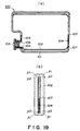
- Figure 9 (c) is a perspective view thereof when the bottom portion takes a top position.
- Figure 11, (b) is a side view thereof.
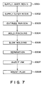
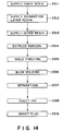
- Figure 14 is a flow chart of manufacturing steps of the ink container according to the third. embodiment of the present invention.
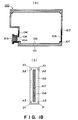
- Figure 18, (b) is a side view thereof.
- the ink container 100 of Figure 1 has the inner wall 102 separable from the outer wall 101 constituting an outer casing or housing, and the ink can be accommodated in the space defined by the inner wall 102 (ink accommodating portion).
- the thickness of the outer wall 101 is sufficiently larger than that of the inner wall 102 so that the outer wall 101 hardly deforms despite the deformation of the inner wall 102 due to the discharging of the ink to the outside.
- the outer wall is provided with an air vent 105 for permission of air introduction.
- the inner wall has a welded portion(pinch-off portion) 104 where the inner wall is supported by the outer wall.
- the air is introduced through the air vent 105 into between the inner wall 102 and the outer wall 101, and the surfaces of the inner wall can be deformed smoothly, thus permitting the negative pressure to be stably maintained.
- the space between the inner wall and the outer wall is in fluid communication with the ambience through the air vent. Then, the force provided by the inner wall and the meniscus force at the ejection outlet of the recording head balance so that the ink is retained ( Figure 2, (b1) and (b2)).
- the precedence order is determined by the configuration of the liquid container, corner conditions such as film thickness, the position of the pinch-off portion where the inner wall is welded and is sandwiched by the outer wall, or the like.
- Designated by 103 is an ink supplying portion for the ink supply from the inside to the outside of the container, and functions as a connecting portion with an ink receiving portion of the ink jet head side unshown.
- the ink container of an embodiment of the present invention has a double wall structure of molding resin material, wherein the outer wall has a thickness to provide high strength, and the inner wall is of soft material with small thickness, thus permitting it to follow the volume variation of the ink. It is preferable that the inner wall has an anti-ink property, and the outer wall has a shock resistant property or the like.
- the materials of the inside resin material and the outside resin material are so selected as to avoid the welding of the resin materials at the contact portion therebetween, or a chemical compound may be added to one of the resin materials when it is supplied into the mold to make them separable.
- the inside material or the outside material may be of multi-layer structure so that the resin materials are supplied in such a manner that different kind materials are present in the contact portion.
- the supply of the inside resin material is uniform along the circumference idealy, but it may be locally thin to provide a structure easily followable to the variation of the inside pressure. The locally thin part will extend in the direction of supply of the resin material.
- FIG. 8 (b1) and (b2) shows the ink container at step S306 in the case that they are separated by vacuum.
- the molding resin materials of the inner wall and the outer wall have different thermal expansion coefficients (shrinkage rates).
- the separation is effected automatically by decrease of the temperature of the molded product after the blow molding, so that the number of manufacturing steps can be decreased.
- the portion having been sandwiched by the molds during the blow molding may be imparted by external force after the molding to separate the outer wall from the inner wall, and the gap therebetween may be brought into communication with the air, so that the gap can be used as an air vent. This is preferable in the case of the container for ink jet recording since then the number of manufacturing steps can be reduced.
- the amount of the injected ink may preferably be approx. 90% of the volume of the ink accommodating portion, since then the leakage of the ink can be avoided even upon the external force exerted thereto, the temperature change or the pressure change.
- the resin having the hydro carbon structure wherein the polymer molecules have only the C-C bond and C-H bond is called a non-polar polymer.
- a polymer containing a large part of polar atom such as O, S, N, halogen is called a polar polymer.
- the polar polymer has a large cohesive power in the molecules thus providing a large binding power.
- the ink container of embodiment 2 can be more easily produced when the step of welding the air blow port member and the step of welding the ink supply portion are added, than when the maximum surface area side is provided in a direction of welded portion, that is, the direction perpendicular to the direction relative to parison supply direction, in the case that the ink supplying portion is along the parison supply direction similarly to the first embodiment.
- a plurality of walls are provided such that the ink container follows the inside due to the decrease of the ink in the ink container.
- at least one of the angles of the corners ⁇ 2 of at a plurality of opposing inner walls as regards the corners ⁇ formed by the surfaces including the ink supplying portion is not more than 90 degrees, so that the deformation confinement portion function is provided.
- 1(a), designated by 121 is an outer wall of the ink container, and 122 is an inner wall of the ink container.
- the separation layer 129 is separable from the outer wall 121 and from the inner wall 122, the separation layer may be contacted with or spaced from the outer wall or the inner wall. In any case, only the space between the separation layer 129 and the outer wall 121 is in fluid communication with the outside through an air vent formed in the outer wall 121.
- the inner wall 122 and the separation layer 129 may be integral.
- an unshown ink introduction portion of the head side is connected through the ink discharge permission member 126, by which the ink jet recording head can be supplied with the ink.
- the ink receiving portion of the recording head is in the form of an ink supply tube as shown in Figure 5, (a) to accomplish the stabilized ink supply, in many cases. If the moldability of the ink supplying portion 123 is good, the connection with the ink jet recording head is assured, so that the ink leakage through the connecting portion does not occur, and the mounting-and-demounting of the ink container relative to the ink jet recording head can be repeated, and therefore, it is desirable.
- the manufacturing method of this embodiment uses the blow molding method as in the first and second embodiment.
- the blow molding method includes an one using injection blow, an one using direct blow, an one using double wall blow.
- the direct blow molding method will be described, particularly as to the portion different from the first and second embodiments.
- step S317 the container is separated from the metal mold (step S317), and the ink is injected (step S318). Thereafter, the cap including the ink discharge permission member 126 is mounted (step S319).
- the similar effect can be provided irrespective of the configuration of the ink container.
- the configuration of the container is symmetrical, and the pinch-off portion is faced to a side adjacent to the side having the maximum area, since then the negative pressure can be produced. More particularly, by resisting the deformation of the inner wall at the position opposed through the maximum area side, the deformation of the maximum side due to the ink consumption can be made regular. This further stabilizes the negative pressure together with the above-described corner deformation confinement.
- the corners and crossing portions between surfaces are slightly rounded.
- the manufacturing method in the foregoing embodiments are usable for manufacturing the container of this embodiment, if the portions of the metal mold 208( Figure 12) corresponding to the corners and crossing portions between sides are rounded.
- the manufacturing of the metal mold is easier, so that the productivity is improved, and therefore, the cost is reduced.
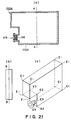
- Figure 21 is a schematic view of an ink container according to embodiment 6.
- the property thereof is suitable for an ink container.
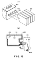
- Figure1 5 (a) is a schematic view of a recording head as a recording means connectable with the ink container of the present invention, and (b) shows the recording head and the ink container connected with each other.
- Designated by 402 is an ink supply tube for introducing the ink into the recording head portion, and it has at one end a filter 403 for trapping the foreign matter or the bubble.
- the ink supplying portion of the ink container is disposed at a lower position than the center thereof.
- the head unit 401 and the ink container 100 are fixing-and-supported on a carriage of the ink jet recording apparatus by unshown positioning means, wherein the recording head and the ink container are respectively detachable.
- the forward and rearward rotation of the driving motor 513 is transmitted to a lead screw 504 through drive transmission gears 511 and 509 to rotate it, and the carriage has a pin(unshown) engageable with a spiral groove 505 of the lead screw 504. By this, the carriage is reciprocated in a longitudinal direction of the recording apparatus.
- the capping cleaning sucking recovery are carried out when the carriage is at the home position by the operation of the lead screw 505. Any other known mechanism is usable for this purpose.
- connection pads 452 of the recording head unit mounted to the carriage are brought into contact to the connection pad 531 by the rotation of the connecting plate 530 provided on the carriage about a predetermined axis, thus establishing the electrical connection. Since a connector is not used, no excessive force is applied to the recording head.
Landscapes
- Ink Jet (AREA)
Applications Claiming Priority (12)
| Application Number | Priority Date | Filing Date | Title |
|---|---|---|---|
| JP90895/95 | 1995-04-17 | ||
| JP9089595 | 1995-04-17 | ||
| JP9089595 | 1995-04-17 | ||
| JP141947/95 | 1995-06-08 | ||
| JP14194795 | 1995-06-08 | ||
| JP14194795 | 1995-06-08 | ||
| JP1287696 | 1996-01-29 | ||
| JP12876/96 | 1996-01-29 | ||
| JP1287696 | 1996-01-29 | ||
| JP85251/96 | 1996-04-08 | ||
| JP8525196 | 1996-04-08 | ||
| JP08525196A JP3251845B2 (ja) | 1995-04-17 | 1996-04-08 | 負圧を与える液体収納容器、該容器の製造方法、該容器とインクジェット記録ヘッドとを一体化したインクジェットカートリッジ及びインクジェット記録装置 |
Publications (3)
| Publication Number | Publication Date |
|---|---|
| EP0738605A2 true EP0738605A2 (de) | 1996-10-23 |
| EP0738605A3 EP0738605A3 (de) | 1998-01-14 |
| EP0738605B1 EP0738605B1 (de) | 2004-10-27 |
Family
ID=27455887
Family Applications (1)
| Application Number | Title | Priority Date | Filing Date |
|---|---|---|---|
| EP96105946A Expired - Lifetime EP0738605B1 (de) | 1995-04-17 | 1996-04-16 | Flüssigkeitsbehälter für negativen Druck, Herstellungsverfahren, Tintenstrahlkassette mit dem Flüssigkeitsbehälter und einem Tintenstrahl-Aufzeichnungskopf als Einheit und Tintenstrahl-Aufzeichnungsgerät |
Country Status (11)
| Country | Link |
|---|---|
| US (4) | US5975330A (de) |
| EP (1) | EP0738605B1 (de) |
| JP (1) | JP3251845B2 (de) |
| KR (1) | KR100222280B1 (de) |
| CN (3) | CN1059157C (de) |
| AT (1) | ATE280675T1 (de) |
| AU (1) | AU5070696A (de) |
| CA (1) | CA2174285C (de) |
| DE (1) | DE69633694T2 (de) |
| HK (1) | HK1011955A1 (de) |
| TW (1) | TW460388B (de) |
Cited By (25)
| Publication number | Priority date | Publication date | Assignee | Title |
|---|---|---|---|---|
| EP0791465A2 (de) * | 1996-02-23 | 1997-08-27 | Canon Kabushiki Kaisha | Flüssigkeitsbehälter und Verfahren zu dessen Herstellung, Tintenstrahlkassette und Tintenstrahlaufzeichnungsgerät |
| EP0818316A2 (de) * | 1996-07-01 | 1998-01-14 | Canon Kabushiki Kaisha | Kassette als Flüssigkeitsstrahlkopf und zugehöriger Flüssigkeitsbehälter |
| EP0705703A3 (de) * | 1994-10-04 | 1998-01-21 | Hewlett-Packard Company | Fugenlose Rahmen aus zwei Materialien für thermische Farbstrahlkassetten |
| EP0822085A2 (de) * | 1996-08-02 | 1998-02-04 | Canon Kabushiki Kaisha | Flüssigkeitsbehälter und Verfahren zu dessen Herstellung und Tintenstrahlkassette |
| EP0829365A2 (de) * | 1996-09-11 | 1998-03-18 | Canon Kabushiki Kaisha | Verfahren zur Flüssigkeitseinspritzung und unter Verwendung dieses Verfahrens gefüllter Flüssigkeitsbehälter |
| EP0853001A2 (de) * | 1997-01-08 | 1998-07-15 | Brother Kogyo Kabushiki Kaisha | Farbstoffpatrone, Herstellungsverfahren und Farbzufuhr |
| EP0857571A2 (de) * | 1997-01-24 | 1998-08-12 | Seiko Epson Corporation | Tintenstrahlaufzeichnungsgerät und Tank für Reaktionslösung |
| EP0865925A1 (de) * | 1997-03-17 | 1998-09-23 | Pelikan Produktions Ag | Tintenbehälter für einen Tintenstrahl-Drucker oder -Plotter |
| EP0956958A2 (de) * | 1998-04-28 | 1999-11-17 | Canon Kabushiki Kaisha | Farbstrahlaufzeichnungsvorrichtung |
| EP0925935A3 (de) * | 1997-12-25 | 2000-06-14 | Canon Kabushiki Kaisha | Flüssigkeitsversorgungsverfahren, Vorrichtung, Tintenbehälter, Kassette und Nachfüllbehälter und Druckkopfkassette mit einer solchen Vorrichtung |
| EP1013448A2 (de) | 1998-12-24 | 2000-06-28 | Canon Kabushiki Kaisha | Flüssigkeitszuführungssystem, Flüssigkeitsbehälter und Druckkopfkassete |
| EP1013447A3 (de) * | 1998-12-24 | 2000-08-30 | Canon Kabushiki Kaisha | Flüssigkeitszufuhrvorrichtung und Restflüssigkeiterfassungsverfahren dafür |
| EP1053873A1 (de) * | 1999-04-27 | 2000-11-22 | Canon Kabushiki Kaisha | Flüssigkeitsbehälter, Flüssigkeitsversorgungssystem, und Methode zur Herstellung eines solchen Behälters |
| EP1053875A1 (de) * | 1999-04-27 | 2000-11-22 | Canon Kabushiki Kaisha | Tintenbehälter, Halter für den Tintenbehälter, Tintenstrahlaufzeichnungsgerät den Halter beinhaltend und Methode zum Einsetzen des Tintenbehälters in den Halter |
| EP1065061A2 (de) * | 1999-06-24 | 2001-01-03 | Canon Kabushiki Kaisha | Flüssigkeitszuführmethode, Flüssigkeitsvorratsbehälter, Behälter für unterdruckerzeugendes Teil und Flüssigkeitsbehälter |
| EP1063090A3 (de) * | 1999-06-24 | 2001-09-12 | Canon Kabushiki Kaisha | Flüssigkeitszufuhrvorrichtung und Flüssigkeitsbehälter dafür |
| EP1147903A1 (de) * | 2000-04-18 | 2001-10-24 | Canon Aptex Kabushiki Kaisha | Tintenbehälter und Tintenstrahlpatrone |
| US6435673B1 (en) * | 1999-06-24 | 2002-08-20 | Canon Kabushiki Kaisha | Liquid container, method of manufacture therefor, ink jet cartridge that uses such container, and ink jet recording apparatus |
| US6471343B1 (en) * | 1999-06-24 | 2002-10-29 | Canon Kabushiki Kaisha | Ink supply system and ink jet recording apparatus |
| US6550898B2 (en) | 1999-04-27 | 2003-04-22 | Canon Kabushiki Kaisha | Liquid supply system, liquid supply container, capillary force generating member container, ink jet cartridge and ink jet recording apparatus |
| US6598963B1 (en) | 1999-04-27 | 2003-07-29 | Canon Kabushiki Kaisha | Liquid supplying system and liquid supply container |
| US6719415B1 (en) | 1999-04-27 | 2004-04-13 | Canon Kabushiki Kaisha | Ink container, valve unit, ink container manufacturing method, ink jet head cartridge and recording apparatus |
| WO2006065352A1 (en) * | 2004-12-15 | 2006-06-22 | Hewlett-Packard Development Company, L.P. | Fluid reservoir and ink pen assembly |
| EP2810780A3 (de) * | 2013-06-05 | 2016-05-25 | Seiko Epson Corporation | Flüssigkeitsaufbewahrungsbehälter |
| US9522540B2 (en) | 2007-10-12 | 2016-12-20 | Videojet Technologies, Inc. | Container and method for liquid storage and dispensing |
Families Citing this family (42)
| Publication number | Priority date | Publication date | Assignee | Title |
|---|---|---|---|---|
| JP3251845B2 (ja) * | 1995-04-17 | 2002-01-28 | キヤノン株式会社 | 負圧を与える液体収納容器、該容器の製造方法、該容器とインクジェット記録ヘッドとを一体化したインクジェットカートリッジ及びインクジェット記録装置 |
| JP3368190B2 (ja) * | 1997-10-21 | 2003-01-20 | キヤノン株式会社 | インクジェット記録装置 |
| JP2001063098A (ja) * | 1999-04-27 | 2001-03-13 | Canon Inc | 液体収納容器、該液体収納容器に用いられる弁機構および液体供給容器 |
| US6443567B1 (en) * | 1999-04-27 | 2002-09-03 | Canon Kabushiki Kaisha | Liquid ejecting cartridge and recording device using same |
| JP2001063099A (ja) | 1999-06-23 | 2001-03-13 | Canon Inc | インクタンク、インクタンクを搭載するインクジェット記録装置、およびインクタンクの包装パッケージ |
| US6505923B1 (en) * | 1999-06-24 | 2003-01-14 | Canon Kabushiki Kaisha | Liquid supply system, liquid supply container and negative pressure generating member container used for the same system, and ink jet recording apparatus using the same system |
| JP2003053966A (ja) * | 2000-06-12 | 2003-02-26 | Seiko Epson Corp | インクジェット式記録ヘッド |
| EP1197338A1 (de) | 2000-10-05 | 2002-04-17 | Canon Kabushiki Kaisha | Flüssigkeitsbehälter und Verfahren zur Trennung des Behälters |
| CN1122626C (zh) | 2000-10-05 | 2003-10-01 | 佳能株式会社 | 液体容器及其制造方法,以及用于液体容器制造方法的金属模具 |
| JP4834260B2 (ja) * | 2000-10-05 | 2011-12-14 | キヤノン株式会社 | 液体収納容器、および該容器の製造方法 |
| DE20021321U1 (de) * | 2000-12-16 | 2001-03-22 | Protechna Sa, Fribourg/Freiburg | Transport- und Lagerbehälter für Flüssigkeiten |
| US6371605B1 (en) | 2001-03-21 | 2002-04-16 | Lexmark International, Inc. | Ink jet printer ink cartridge manufacturing method |
| US6536887B2 (en) * | 2001-04-25 | 2003-03-25 | Hewlett-Packard Company | Over-molded regulator bag for an ink delivery system |
| JP2003155063A (ja) * | 2001-08-03 | 2003-05-27 | Canon Inc | 液体収納容器、および該液体収納容器の製造方法 |
| ATE326348T1 (de) | 2001-10-05 | 2006-06-15 | Canon Kk | Tintenbehälter, flüssigkeitszufuhrvorrichtung und aufzeichnungsvorrichtung |
| US6585362B2 (en) * | 2001-10-05 | 2003-07-01 | Eastman Kodak Company | Ink composition, ink cartridge having ink composition, and method of filling ink cartridge |
| US6863389B2 (en) | 2003-01-15 | 2005-03-08 | Xerox Corporation | Liquid ink cartridge using viscous gel |
| JP2004268575A (ja) * | 2003-02-19 | 2004-09-30 | Seiko Epson Corp | 液体貯留手段及び液体噴射装置 |
| JP2004306505A (ja) * | 2003-04-09 | 2004-11-04 | Brother Ind Ltd | インクパッケージ |
| US6905198B2 (en) * | 2003-07-24 | 2005-06-14 | Hewlett-Packard Development Company, L.P. | Liquid supply vessel |
| US7033010B2 (en) * | 2003-09-16 | 2006-04-25 | Hewlett-Packard Development, L.P. | Ink delivery apparatus with collapsible ink chamber and method of use |
| US7278722B2 (en) * | 2003-11-25 | 2007-10-09 | Brother Kogyo Kabushiki Kaisha | Ink cartridge |
| JP4137010B2 (ja) * | 2004-06-11 | 2008-08-20 | キヤノン株式会社 | インクジェット記録装置に用いる液体収納容器 |
| DE602005021730D1 (de) * | 2004-08-23 | 2010-07-22 | Konica Minolta Med & Graphic | Tintenstrahlpatrone für Tintenstrahlaufzeichnungsgerät, Tintenstrahlaufzeichnungsgerät und Tintenversorgungsverfahren |
| JP2006248159A (ja) * | 2005-03-14 | 2006-09-21 | Seiko Epson Corp | インクカートリッジおよびその製造方法 |
| JP4746456B2 (ja) | 2006-03-20 | 2011-08-10 | 株式会社東芝 | 液滴噴射塗布ヘッドモジュール、液滴噴射塗布装置及び塗布体の製造方法 |
| JP5224754B2 (ja) | 2006-11-29 | 2013-07-03 | キヤノン株式会社 | インクジェット記録装置 |
| JP2008230137A (ja) * | 2007-03-22 | 2008-10-02 | Fujifilm Corp | 液体吐出ヘッドの背圧調整装置 |
| JP5353565B2 (ja) * | 2009-03-17 | 2013-11-27 | 株式会社リコー | 液体収容容器及び画像形成装置 |
| JP5359722B2 (ja) * | 2009-09-15 | 2013-12-04 | 株式会社リコー | 画像形成装置 |
| JP5565029B2 (ja) * | 2010-03-29 | 2014-08-06 | セイコーエプソン株式会社 | 液体容器および液体消費装置 |
| FR2980998B1 (fr) * | 2011-10-07 | 2013-11-15 | Cadorit Ag | Procede de production d'un bouchon |
| CN103373074B (zh) * | 2012-04-26 | 2016-12-14 | 珠海纳思达企业管理有限公司 | 一种墨盒 |
| JP6458469B2 (ja) * | 2014-12-02 | 2019-01-30 | セイコーエプソン株式会社 | 液体供給システム |
| JP2016141125A (ja) * | 2015-02-05 | 2016-08-08 | セイコーエプソン株式会社 | 液体収容体 |
| JP6730794B2 (ja) * | 2015-09-29 | 2020-07-29 | 北海製罐株式会社 | 合成樹脂製多重ボトル |
| CN107554932B (zh) * | 2017-09-29 | 2023-10-31 | 微能聚粒环境科技发展(南京)有限公司 | 一种双层纸筒包装容器 |
| JP7182974B2 (ja) * | 2017-10-17 | 2022-12-05 | キヤノン株式会社 | インクタンク及びインクジェット記録装置 |
| JP7182973B2 (ja) * | 2017-10-17 | 2022-12-05 | キヤノン株式会社 | インクタンク及びインクジェット記録装置 |
| US10654279B2 (en) * | 2017-10-17 | 2020-05-19 | Canon Kabushiki Kaisha | Ink tank and ink jet recording apparatus |
| US20190276298A1 (en) * | 2018-03-09 | 2019-09-12 | Dispenser Packaging, LLC | Liquid Dispense System |
| CN116457214A (zh) * | 2020-10-30 | 2023-07-18 | 惠普发展公司,有限责任合伙企业 | 空气吸入防止 |
Citations (6)
| Publication number | Priority date | Publication date | Assignee | Title |
|---|---|---|---|---|
| US4119034A (en) * | 1977-02-04 | 1978-10-10 | Siemens Aktiengesellschaft | Leakproof ink supply reservoir |
| US4689642A (en) * | 1984-03-30 | 1987-08-25 | Canon Kabushiki Kaisha | Ink-jet recording head with an elastic ink tank in a sealed casing held at a partial vacuum and having a breakable seal |
| US4940997A (en) * | 1989-08-08 | 1990-07-10 | Hewlett-Packard Company | Out-of-ink sensing method |
| EP0493978A1 (de) * | 1991-01-03 | 1992-07-08 | Hewlett-Packard Company | Tintenzufuhrsystem für einen Tintenstrahldrucker |
| EP0543315A2 (de) * | 1991-11-18 | 1993-05-26 | Canon Kabushiki Kaisha | Tintenbehälter und Tintenstrahlaufzeichnungsgerät damit versehen |
| EP0623444A1 (de) * | 1993-05-03 | 1994-11-09 | Hewlett-Packard Company | Rahmen aus zwei Materialien mit verschiedenen Eigenschaften für thermischem Tintenstrahldruckkopf |
Family Cites Families (35)
| Publication number | Priority date | Publication date | Assignee | Title |
|---|---|---|---|---|
| FR1436158A (fr) * | 1964-04-01 | 1966-04-22 | Continental Can Co | Procédé et appareil de fabrication de récipients enduits |
| DE2831999C2 (de) * | 1978-07-20 | 1980-10-23 | Siemens Ag, 1000 Berlin Und 8000 Muenchen | Behälter mit veränderbarem Volumen |
| GB2063175B (en) * | 1979-11-06 | 1984-02-15 | Shinshu Seiki Kk | Ink jet printer |
| JPS5667269A (en) * | 1979-11-06 | 1981-06-06 | Seiko Epson Corp | Ink tank |
| JPS58171328A (ja) * | 1982-03-30 | 1983-10-08 | 坂本 次康 | 運搬容器及びその製造方法 |
| US4558326A (en) * | 1982-09-07 | 1985-12-10 | Konishiroku Photo Industry Co., Ltd. | Purging system for ink jet recording apparatus |
| US4509062A (en) * | 1982-11-23 | 1985-04-02 | Hewlett-Packard Company | Ink reservoir with essentially constant negative back pressure |
| JPS6193246A (ja) * | 1984-10-11 | 1986-05-12 | Mazda Motor Corp | エンジンの空燃比制御装置 |
| DE3442092A1 (de) * | 1984-11-17 | 1986-05-28 | Kautex Werke Reinold Hagen AG, 5300 Bonn | Verfahren zum herstellen einer mit einer verschliessbaren oeffnung versehenen verpackung und nach diesem verfahren hergestellte verpackung |
| JPS6312427A (ja) * | 1986-06-25 | 1988-01-19 | 東洋製罐株式会社 | プラスチツク製押出し多層容器 |
| US4816093A (en) * | 1987-09-25 | 1989-03-28 | Robbins Edward S Iii | Separable laminate container |
| GB8925472D0 (en) * | 1989-11-10 | 1989-12-28 | Ici Plc | Container |
| USD332130S (en) * | 1990-06-07 | 1992-12-29 | Mauser-Werke Gmbh | Storage container |
| JP3119375B2 (ja) | 1990-09-21 | 2000-12-18 | キヤノン株式会社 | 印字評価方法及び印字評価装置 |
| EP0478244B1 (de) * | 1990-09-22 | 1997-08-13 | Canon Kabushiki Kaisha | Tintenkassette und Farbstrahlvorrichtung zur Benutzung dieser Kassette |
| US5344045A (en) * | 1990-12-17 | 1994-09-06 | The Coca-Cola Company | Liquid container system |
| US5242085A (en) * | 1990-12-17 | 1993-09-07 | The Coca-Cola Company | Liquid container system |
| JPH06211243A (ja) * | 1990-12-28 | 1994-08-02 | Yoshino Kogyosho Co Ltd | 農薬用積層ボトル |
| JP3014058B2 (ja) * | 1990-12-28 | 2000-02-28 | 株式会社吉野工業所 | 積層ボトルおよびその製造方法 |
| US5301838A (en) * | 1991-01-23 | 1994-04-12 | Continental Pet Technologies, Inc. | Multilayer bottle with separable inner layer and method for forming same |
| JPH04267727A (ja) * | 1991-02-05 | 1992-09-24 | Keisuke Ito | 多層成形容器及びその製造方法 |
| JP3062631B2 (ja) * | 1991-08-05 | 2000-07-12 | 株式会社吉野工業所 | 積層ボトル |
| EP0550772B1 (de) * | 1991-08-05 | 1998-12-09 | Yoshino Kogyosho Co., Ltd. | Laminierte flasche sowie verfahren zu ihrer herstellung |
| JP3015165B2 (ja) * | 1991-08-30 | 2000-03-06 | キヤノン株式会社 | インク容器、これを用いた記録ヘッドユニットおよびこれを搭載する記録装置 |
| JP3108147B2 (ja) * | 1991-09-18 | 2000-11-13 | 釜屋化学工業株式会社 | 容器およびその製造方法 |
| JPH05213373A (ja) * | 1991-09-18 | 1993-08-24 | Kamaya Kagaku Kogyo Co Ltd | 容器およびその製造方法 |
| DE4139555A1 (de) * | 1991-09-18 | 1993-03-25 | Gaplast Gmbh | Behaelter |
| JP3207908B2 (ja) * | 1992-03-13 | 2001-09-10 | キヤノン株式会社 | インク容器 |
| US5515092A (en) * | 1992-03-18 | 1996-05-07 | Hewlett-Packard Company | Two material frame having dissimilar properties for thermal ink-jet cartridge |
| WO1993023311A1 (en) * | 1992-05-11 | 1993-11-25 | Yoshino Kogyosho Co., Ltd. | Laminated bottle and pump unit for laminated bottle |
| JPH05318756A (ja) * | 1992-05-22 | 1993-12-03 | Canon Inc | インク容器 |
| JP3098619B2 (ja) * | 1992-06-25 | 2000-10-16 | 大阪瓦斯株式会社 | 燃料電池 |
| JPH0627523A (ja) * | 1992-07-13 | 1994-02-04 | Olympus Optical Co Ltd | データ写し込み装置 |
| US5440333A (en) * | 1992-12-23 | 1995-08-08 | Hewlett-Packard Company | Collapsible ink reservoir and ink-jet cartridge with protective bonding layer for the pressure regulator |
| JP3251845B2 (ja) * | 1995-04-17 | 2002-01-28 | キヤノン株式会社 | 負圧を与える液体収納容器、該容器の製造方法、該容器とインクジェット記録ヘッドとを一体化したインクジェットカートリッジ及びインクジェット記録装置 |
-
1996
- 1996-04-08 JP JP08525196A patent/JP3251845B2/ja not_active Expired - Fee Related
- 1996-04-13 TW TW085104410A patent/TW460388B/zh not_active IP Right Cessation
- 1996-04-15 US US08/635,263 patent/US5975330A/en not_active Expired - Lifetime
- 1996-04-16 EP EP96105946A patent/EP0738605B1/de not_active Expired - Lifetime
- 1996-04-16 AU AU50706/96A patent/AU5070696A/en not_active Abandoned
- 1996-04-16 AT AT96105946T patent/ATE280675T1/de not_active IP Right Cessation
- 1996-04-16 KR KR1019960011365A patent/KR100222280B1/ko not_active IP Right Cessation
- 1996-04-16 DE DE69633694T patent/DE69633694T2/de not_active Expired - Lifetime
- 1996-04-16 CA CA002174285A patent/CA2174285C/en not_active Expired - Fee Related
- 1996-04-17 CN CN96105066A patent/CN1059157C/zh not_active Expired - Fee Related
-
1998
- 1998-12-10 HK HK98113124A patent/HK1011955A1/xx not_active IP Right Cessation
-
1999
- 1999-06-17 US US09/334,657 patent/US6145970A/en not_active Expired - Lifetime
- 1999-06-17 US US09/334,676 patent/US6440352B1/en not_active Expired - Lifetime
- 1999-06-17 US US09/334,677 patent/US6250748B1/en not_active Expired - Lifetime
-
2000
- 2000-03-31 CN CN00105316A patent/CN1119247C/zh not_active Expired - Fee Related
- 2000-03-31 CN CN00105317A patent/CN1108237C/zh not_active Expired - Fee Related
Patent Citations (6)
| Publication number | Priority date | Publication date | Assignee | Title |
|---|---|---|---|---|
| US4119034A (en) * | 1977-02-04 | 1978-10-10 | Siemens Aktiengesellschaft | Leakproof ink supply reservoir |
| US4689642A (en) * | 1984-03-30 | 1987-08-25 | Canon Kabushiki Kaisha | Ink-jet recording head with an elastic ink tank in a sealed casing held at a partial vacuum and having a breakable seal |
| US4940997A (en) * | 1989-08-08 | 1990-07-10 | Hewlett-Packard Company | Out-of-ink sensing method |
| EP0493978A1 (de) * | 1991-01-03 | 1992-07-08 | Hewlett-Packard Company | Tintenzufuhrsystem für einen Tintenstrahldrucker |
| EP0543315A2 (de) * | 1991-11-18 | 1993-05-26 | Canon Kabushiki Kaisha | Tintenbehälter und Tintenstrahlaufzeichnungsgerät damit versehen |
| EP0623444A1 (de) * | 1993-05-03 | 1994-11-09 | Hewlett-Packard Company | Rahmen aus zwei Materialien mit verschiedenen Eigenschaften für thermischem Tintenstrahldruckkopf |
Cited By (55)
| Publication number | Priority date | Publication date | Assignee | Title |
|---|---|---|---|---|
| EP0705703A3 (de) * | 1994-10-04 | 1998-01-21 | Hewlett-Packard Company | Fugenlose Rahmen aus zwei Materialien für thermische Farbstrahlkassetten |
| US5896153A (en) * | 1994-10-04 | 1999-04-20 | Hewlett-Packard Company | Leak resistant two-material frame for ink-jet print cartridge |
| EP0791465A2 (de) * | 1996-02-23 | 1997-08-27 | Canon Kabushiki Kaisha | Flüssigkeitsbehälter und Verfahren zu dessen Herstellung, Tintenstrahlkassette und Tintenstrahlaufzeichnungsgerät |
| EP0791465A3 (de) * | 1996-02-23 | 1998-05-27 | Canon Kabushiki Kaisha | Flüssigkeitsbehälter und Verfahren zu dessen Herstellung, Tintenstrahlkassette und Tintenstrahlaufzeichnungsgerät |
| CN1077507C (zh) * | 1996-02-23 | 2002-01-09 | 佳能株式会社 | 液体容器及其加工方法 |
| US6290345B1 (en) | 1996-02-23 | 2001-09-18 | Canon Kabushiki Kaisha | Liquid container, manufacturing method, ink jet cartridge, and ink jet recording apparatus |
| EP0818316A2 (de) * | 1996-07-01 | 1998-01-14 | Canon Kabushiki Kaisha | Kassette als Flüssigkeitsstrahlkopf und zugehöriger Flüssigkeitsbehälter |
| US6247806B1 (en) | 1996-07-01 | 2001-06-19 | Canon Kabushiki Kaisha | Liquid ejection head cartridge and liquid container usable therewith |
| EP0818316A3 (de) * | 1996-07-01 | 1998-09-30 | Canon Kabushiki Kaisha | Kassette als Flüssigkeitsstrahlkopf und zugehöriger Flüssigkeitsbehälter |
| US6305794B1 (en) | 1996-08-02 | 2001-10-23 | Canon Kabushiki Kaisha | Liquid container, ink jet cartridge having same and manufacturing method of the container |
| EP0822085A2 (de) * | 1996-08-02 | 1998-02-04 | Canon Kabushiki Kaisha | Flüssigkeitsbehälter und Verfahren zu dessen Herstellung und Tintenstrahlkassette |
| EP0822085A3 (de) * | 1996-08-02 | 1999-06-30 | Canon Kabushiki Kaisha | Flüssigkeitsbehälter und Verfahren zu dessen Herstellung und Tintenstrahlkassette |
| US6328437B1 (en) | 1996-09-11 | 2001-12-11 | Canon Kabushiki Kaisha | Liquid injection method |
| EP0829365A3 (de) * | 1996-09-11 | 1998-11-11 | Canon Kabushiki Kaisha | Verfahren zur Flüssigkeitseinspritzung und unter Verwendung dieses Verfahrens gefüllter Flüssigkeitsbehälter |
| EP0829365A2 (de) * | 1996-09-11 | 1998-03-18 | Canon Kabushiki Kaisha | Verfahren zur Flüssigkeitseinspritzung und unter Verwendung dieses Verfahrens gefüllter Flüssigkeitsbehälter |
| EP0853001A3 (de) * | 1997-01-08 | 1999-04-21 | Brother Kogyo Kabushiki Kaisha | Farbstoffpatrone, Herstellungsverfahren und Farbzufuhr |
| US6109743A (en) * | 1997-01-08 | 2000-08-29 | Brother Kogyo Kabushiki Kaisha | Ink cartridge, process for forming it and liquid ink feeder |
| EP0853001A2 (de) * | 1997-01-08 | 1998-07-15 | Brother Kogyo Kabushiki Kaisha | Farbstoffpatrone, Herstellungsverfahren und Farbzufuhr |
| US6247804B1 (en) | 1997-01-24 | 2001-06-19 | Seiko Epson Corporation | Ink jet recording apparatus with tank for reaction solution and method for producing the tank |
| EP0857571A2 (de) * | 1997-01-24 | 1998-08-12 | Seiko Epson Corporation | Tintenstrahlaufzeichnungsgerät und Tank für Reaktionslösung |
| EP0857571A3 (de) * | 1997-01-24 | 1999-05-06 | Seiko Epson Corporation | Tintenstrahlaufzeichnungsgerät und Tank für Reaktionslösung |
| EP0865925A1 (de) * | 1997-03-17 | 1998-09-23 | Pelikan Produktions Ag | Tintenbehälter für einen Tintenstrahl-Drucker oder -Plotter |
| SG81256A1 (en) * | 1997-12-25 | 2001-06-19 | Canon Kk | Liquid supply method, system, ink container, cartridge and replenishing container and head cartridge usable with system |
| US6345888B1 (en) * | 1997-12-25 | 2002-02-12 | Canon Kabushiki Kaisha | Liquid supply method, system, ink container, cartridge and replenishing container and head cartridge usable with system |
| SG115369A1 (en) * | 1997-12-25 | 2005-10-28 | Canon Kk | Liquid supply method, system, ink container, cartridge and replenishing container and head cartridge usable with system |
| EP0925935A3 (de) * | 1997-12-25 | 2000-06-14 | Canon Kabushiki Kaisha | Flüssigkeitsversorgungsverfahren, Vorrichtung, Tintenbehälter, Kassette und Nachfüllbehälter und Druckkopfkassette mit einer solchen Vorrichtung |
| EP0956958A3 (de) * | 1998-04-28 | 2001-01-24 | Canon Kabushiki Kaisha | Farbstrahlaufzeichnungsvorrichtung |
| EP0956958A2 (de) * | 1998-04-28 | 1999-11-17 | Canon Kabushiki Kaisha | Farbstrahlaufzeichnungsvorrichtung |
| US6460984B1 (en) * | 1998-04-28 | 2002-10-08 | Canon Kabushiki Kaisha | Liquid supply system, liquid container, head cartridge, ink jet cartridge, liquid supply container, method for coupling the head cartridge with the liquid supply container, communication unit used for the liquid supply system, ink jet recording apparatus provided with the ink jet cartridge opening/closing valve used for the liquid container, and liquid supply container provided with the opening/closing valve |
| EP1013447A3 (de) * | 1998-12-24 | 2000-08-30 | Canon Kabushiki Kaisha | Flüssigkeitszufuhrvorrichtung und Restflüssigkeiterfassungsverfahren dafür |
| EP1013448A3 (de) * | 1998-12-24 | 2000-08-09 | Canon Kabushiki Kaisha | Flüssigkeitszuführungssystem, Flüssigkeitsbehälter und Druckkopfkassete |
| US6575567B2 (en) | 1998-12-24 | 2003-06-10 | Canon Kabushiki Kaisha | Liquid delivery system, liquid container, and head cartridge |
| US6422674B1 (en) | 1998-12-24 | 2002-07-23 | Canon Kabushiki Kaisha | Liquid supply system and liquid residual amount detecting method of liquid supply system |
| EP1013448A2 (de) | 1998-12-24 | 2000-06-28 | Canon Kabushiki Kaisha | Flüssigkeitszuführungssystem, Flüssigkeitsbehälter und Druckkopfkassete |
| EP1053875A1 (de) * | 1999-04-27 | 2000-11-22 | Canon Kabushiki Kaisha | Tintenbehälter, Halter für den Tintenbehälter, Tintenstrahlaufzeichnungsgerät den Halter beinhaltend und Methode zum Einsetzen des Tintenbehälters in den Halter |
| EP1053873A1 (de) * | 1999-04-27 | 2000-11-22 | Canon Kabushiki Kaisha | Flüssigkeitsbehälter, Flüssigkeitsversorgungssystem, und Methode zur Herstellung eines solchen Behälters |
| US6347865B1 (en) | 1999-04-27 | 2002-02-19 | Canon Kabushiki Kaisha | Liquid container, liquid supply system, and method for manufacturing such liquid container |
| US6598963B1 (en) | 1999-04-27 | 2003-07-29 | Canon Kabushiki Kaisha | Liquid supplying system and liquid supply container |
| US6719415B1 (en) | 1999-04-27 | 2004-04-13 | Canon Kabushiki Kaisha | Ink container, valve unit, ink container manufacturing method, ink jet head cartridge and recording apparatus |
| US6805434B2 (en) | 1999-04-27 | 2004-10-19 | Canon Kabushiki Kaisha | Liquid supplying system, liquid supply container, capillary force generating member container, ink jet cartridge and ink jet recording apparatus |
| US6511167B1 (en) | 1999-04-27 | 2003-01-28 | Canon Kabushiki Kaisha | Ink container, holder for ink container, ink jet recording apparatus having holder and mounting method for mounting ink container to holder |
| US6550898B2 (en) | 1999-04-27 | 2003-04-22 | Canon Kabushiki Kaisha | Liquid supply system, liquid supply container, capillary force generating member container, ink jet cartridge and ink jet recording apparatus |
| EP1063090A3 (de) * | 1999-06-24 | 2001-09-12 | Canon Kabushiki Kaisha | Flüssigkeitszufuhrvorrichtung und Flüssigkeitsbehälter dafür |
| US6543886B1 (en) | 1999-06-24 | 2003-04-08 | Canon Kabushiki Kaisha | Liquid supply method, liquid supply container, negative pressure generating member container, and liquid container |
| US6471343B1 (en) * | 1999-06-24 | 2002-10-29 | Canon Kabushiki Kaisha | Ink supply system and ink jet recording apparatus |
| US6435673B1 (en) * | 1999-06-24 | 2002-08-20 | Canon Kabushiki Kaisha | Liquid container, method of manufacture therefor, ink jet cartridge that uses such container, and ink jet recording apparatus |
| US6402308B1 (en) | 1999-06-24 | 2002-06-11 | Canon Kabushiki Kaisha | Liquid supply system and liquid supply vessel used for the same |
| EP1065061A3 (de) * | 1999-06-24 | 2001-11-28 | Canon Kabushiki Kaisha | Flüssigkeitszuführmethode, Flüssigkeitsvorratsbehälter, Behälter für unterdruckerzeugendes Teil und Flüssigkeitsbehälter |
| EP1065061A2 (de) * | 1999-06-24 | 2001-01-03 | Canon Kabushiki Kaisha | Flüssigkeitszuführmethode, Flüssigkeitsvorratsbehälter, Behälter für unterdruckerzeugendes Teil und Flüssigkeitsbehälter |
| US6511168B2 (en) | 2000-04-18 | 2003-01-28 | Canon Aptex Kabushiki Kaisha | Ink container and ink jet cartridge |
| EP1147903A1 (de) * | 2000-04-18 | 2001-10-24 | Canon Aptex Kabushiki Kaisha | Tintenbehälter und Tintenstrahlpatrone |
| WO2006065352A1 (en) * | 2004-12-15 | 2006-06-22 | Hewlett-Packard Development Company, L.P. | Fluid reservoir and ink pen assembly |
| US9522540B2 (en) | 2007-10-12 | 2016-12-20 | Videojet Technologies, Inc. | Container and method for liquid storage and dispensing |
| EP2810780A3 (de) * | 2013-06-05 | 2016-05-25 | Seiko Epson Corporation | Flüssigkeitsaufbewahrungsbehälter |
| US10000334B2 (en) | 2013-06-05 | 2018-06-19 | Seiko Epson Corporation | Liquid holding container |
Also Published As
| Publication number | Publication date |
|---|---|
| HK1011955A1 (en) | 1999-07-23 |
| TW460388B (en) | 2001-10-21 |
| EP0738605B1 (de) | 2004-10-27 |
| JP3251845B2 (ja) | 2002-01-28 |
| JPH09267483A (ja) | 1997-10-14 |
| KR100222280B1 (ko) | 1999-10-01 |
| CN1137978A (zh) | 1996-12-18 |
| MX9601425A (es) | 1997-10-31 |
| CA2174285C (en) | 2001-07-03 |
| DE69633694T2 (de) | 2005-10-20 |
| CN1277920A (zh) | 2000-12-27 |
| CA2174285A1 (en) | 1996-10-18 |
| CN1277921A (zh) | 2000-12-27 |
| US6440352B1 (en) | 2002-08-27 |
| CN1108237C (zh) | 2003-05-14 |
| US6250748B1 (en) | 2001-06-26 |
| CN1059157C (zh) | 2000-12-06 |
| AU5070696A (en) | 1997-01-02 |
| EP0738605A3 (de) | 1998-01-14 |
| CN1119247C (zh) | 2003-08-27 |
| ATE280675T1 (de) | 2004-11-15 |
| US6145970A (en) | 2000-11-14 |
| US5975330A (en) | 1999-11-02 |
| DE69633694D1 (de) | 2004-12-02 |
Similar Documents
| Publication | Publication Date | Title |
|---|---|---|
| EP0738605B1 (de) | Flüssigkeitsbehälter für negativen Druck, Herstellungsverfahren, Tintenstrahlkassette mit dem Flüssigkeitsbehälter und einem Tintenstrahl-Aufzeichnungskopf als Einheit und Tintenstrahl-Aufzeichnungsgerät | |
| CA2198188C (en) | Liquid container, manufacturing method, ink jet cartridge, and ink jet recording apparatus | |
| EP0748692B1 (de) | Tintenbehälter und dessen Herstellungsverfahren, Tintenkartusche und Tintenstrahlgerät | |
| EP0829365B1 (de) | Verfahren zur Flüssigkeitseinspritzung und unter Verwendung dieses Verfahrens gefüllter Flüssigkeitsbehälter | |
| JP3245088B2 (ja) | 液体吐出ヘッドカートリッジ及び該カートリッジに用いられる液体収容容器 | |
| US6305794B1 (en) | Liquid container, ink jet cartridge having same and manufacturing method of the container | |
| JP3342372B2 (ja) | インクジェットプリントシステムに用いられる大容量インク補充容器 | |
| JP2001063759A (ja) | 液体収納容器及びその製造方法、並びにインクジェットカートリッジ及びインクジェット記録装置 | |
| AU731621B2 (en) | Ink container | |
| JPH1044454A (ja) | 液体収納容器、該液体収納容器の製造方法、インクタンクとインクジェットヘッドとを一体化したインクジェットヘッドカートリッジ及びインクジェット記録装置 | |
| AU714551B2 (en) | Ink container | |
| AU741550B2 (en) | Ink container | |
| AU726614B2 (en) | Ink container | |
| JP3245090B2 (ja) | 負圧を与える液体収納容器、該容器とインクジェット記録ヘッドとを一体化したインクジェットカートリッジ及び該容器の製造方法 | |
| JPH1044452A (ja) | 負圧を与える液体収納容器、該容器の製造方法、該容器とインクジェット記録ヘッドとを一体化したインクジェットカートリッジ | |
| JP3251881B2 (ja) | 液体収納容器及び該液体収納容器を備えるインクジェットカートリッジ及び該インクジェットカートリッジを備えるインクジェット記録装置 | |
| JP3311342B2 (ja) | 負圧を与える液体収納容器の製造方法 | |
| JPH1044385A (ja) | 負圧を与える液体収納容器、該容器とインクジェット記録ヘッドとを一体化したインクジェットカートリッジ及びインクジェット記録装置 | |
| JPH1044453A (ja) | 液体収納容器、ヘッドカートリッジおよび記録装置 | |
| JPH1034956A (ja) | インクタンク |
Legal Events
| Date | Code | Title | Description |
|---|---|---|---|
| PUAI | Public reference made under article 153(3) epc to a published international application that has entered the european phase |
Free format text: ORIGINAL CODE: 0009012 |
|
| 17P | Request for examination filed |
Effective date: 19960416 |
|
| AK | Designated contracting states |
Kind code of ref document: A2 Designated state(s): AT BE CH DE DK ES FI FR GB GR IE IT LI LU NL PT SE |
|
| PUAL | Search report despatched |
Free format text: ORIGINAL CODE: 0009013 |
|
| AK | Designated contracting states |
Kind code of ref document: A3 Designated state(s): AT BE CH DE DK ES FI FR GB GR IE IT LI LU NL PT SE |
|
| 17Q | First examination report despatched |
Effective date: 19990907 |
|
| GRAP | Despatch of communication of intention to grant a patent |
Free format text: ORIGINAL CODE: EPIDOSNIGR1 |
|
| GRAS | Grant fee paid |
Free format text: ORIGINAL CODE: EPIDOSNIGR3 |
|
| GRAA | (expected) grant |
Free format text: ORIGINAL CODE: 0009210 |
|
| AK | Designated contracting states |
Kind code of ref document: B1 Designated state(s): AT BE CH DE DK ES FI FR GB GR IE IT LI LU NL PT SE |
|
| PG25 | Lapsed in a contracting state [announced via postgrant information from national office to epo] |
Ref country code: NL Free format text: LAPSE BECAUSE OF FAILURE TO SUBMIT A TRANSLATION OF THE DESCRIPTION OR TO PAY THE FEE WITHIN THE PRESCRIBED TIME-LIMIT Effective date: 20041027 Ref country code: FI Free format text: LAPSE BECAUSE OF FAILURE TO SUBMIT A TRANSLATION OF THE DESCRIPTION OR TO PAY THE FEE WITHIN THE PRESCRIBED TIME-LIMIT Effective date: 20041027 Ref country code: BE Free format text: LAPSE BECAUSE OF FAILURE TO SUBMIT A TRANSLATION OF THE DESCRIPTION OR TO PAY THE FEE WITHIN THE PRESCRIBED TIME-LIMIT Effective date: 20041027 Ref country code: AT Free format text: LAPSE BECAUSE OF FAILURE TO SUBMIT A TRANSLATION OF THE DESCRIPTION OR TO PAY THE FEE WITHIN THE PRESCRIBED TIME-LIMIT Effective date: 20041027 |
|
| REG | Reference to a national code |
Ref country code: GB Ref legal event code: FG4D |
|
| REG | Reference to a national code |
Ref country code: CH Ref legal event code: EP |
|
| REG | Reference to a national code |
Ref country code: CH Ref legal event code: NV Representative=s name: BOVARD AG PATENTANWAELTE |
|
| REG | Reference to a national code |
Ref country code: IE Ref legal event code: FG4D |
|
| REF | Corresponds to: |
Ref document number: 69633694 Country of ref document: DE Date of ref document: 20041202 Kind code of ref document: P |
|
| PG25 | Lapsed in a contracting state [announced via postgrant information from national office to epo] |
Ref country code: SE Free format text: LAPSE BECAUSE OF FAILURE TO SUBMIT A TRANSLATION OF THE DESCRIPTION OR TO PAY THE FEE WITHIN THE PRESCRIBED TIME-LIMIT Effective date: 20050127 Ref country code: GR Free format text: LAPSE BECAUSE OF FAILURE TO SUBMIT A TRANSLATION OF THE DESCRIPTION OR TO PAY THE FEE WITHIN THE PRESCRIBED TIME-LIMIT Effective date: 20050127 Ref country code: DK Free format text: LAPSE BECAUSE OF FAILURE TO SUBMIT A TRANSLATION OF THE DESCRIPTION OR TO PAY THE FEE WITHIN THE PRESCRIBED TIME-LIMIT Effective date: 20050127 |
|
| PG25 | Lapsed in a contracting state [announced via postgrant information from national office to epo] |
Ref country code: ES Free format text: LAPSE BECAUSE OF FAILURE TO SUBMIT A TRANSLATION OF THE DESCRIPTION OR TO PAY THE FEE WITHIN THE PRESCRIBED TIME-LIMIT Effective date: 20050207 |
|
| REG | Reference to a national code |
Ref country code: HK Ref legal event code: GR Ref document number: 1011955 Country of ref document: HK |
|
| PG25 | Lapsed in a contracting state [announced via postgrant information from national office to epo] |
Ref country code: LU Free format text: LAPSE BECAUSE OF NON-PAYMENT OF DUE FEES Effective date: 20050416 |
|
| PG25 | Lapsed in a contracting state [announced via postgrant information from national office to epo] |
Ref country code: IE Free format text: LAPSE BECAUSE OF NON-PAYMENT OF DUE FEES Effective date: 20050418 |
|
| NLV1 | Nl: lapsed or annulled due to failure to fulfill the requirements of art. 29p and 29m of the patents act | ||
| ET | Fr: translation filed | ||
| PLBE | No opposition filed within time limit |
Free format text: ORIGINAL CODE: 0009261 |
|
| STAA | Information on the status of an ep patent application or granted ep patent |
Free format text: STATUS: NO OPPOSITION FILED WITHIN TIME LIMIT |
|
| 26N | No opposition filed |
Effective date: 20050728 |
|
| PG25 | Lapsed in a contracting state [announced via postgrant information from national office to epo] |
Ref country code: PT Free format text: LAPSE BECAUSE OF NON-PAYMENT OF DUE FEES Effective date: 20050327 |
|
| REG | Reference to a national code |
Ref country code: CH Ref legal event code: PFA Owner name: CANON KABUSHIKI KAISHA Free format text: CANON KABUSHIKI KAISHA#3-30-2 SHIMOMARUKO#OHTA-KU, TOKYO (JP) -TRANSFER TO- CANON KABUSHIKI KAISHA#3-30-2 SHIMOMARUKO#OHTA-KU, TOKYO (JP) |
|
| PGFP | Annual fee paid to national office [announced via postgrant information from national office to epo] |
Ref country code: CH Payment date: 20130417 Year of fee payment: 18 |
|
| PGFP | Annual fee paid to national office [announced via postgrant information from national office to epo] |
Ref country code: GB Payment date: 20140414 Year of fee payment: 19 |
|
| PGFP | Annual fee paid to national office [announced via postgrant information from national office to epo] |
Ref country code: DE Payment date: 20140430 Year of fee payment: 19 Ref country code: FR Payment date: 20140428 Year of fee payment: 19 Ref country code: IT Payment date: 20140402 Year of fee payment: 19 |
|
| REG | Reference to a national code |
Ref country code: CH Ref legal event code: PL |
|
| PG25 | Lapsed in a contracting state [announced via postgrant information from national office to epo] |
Ref country code: LI Free format text: LAPSE BECAUSE OF NON-PAYMENT OF DUE FEES Effective date: 20140430 Ref country code: CH Free format text: LAPSE BECAUSE OF NON-PAYMENT OF DUE FEES Effective date: 20140430 |
|
| REG | Reference to a national code |
Ref country code: DE Ref legal event code: R119 Ref document number: 69633694 Country of ref document: DE |
|
| GBPC | Gb: european patent ceased through non-payment of renewal fee |
Effective date: 20150416 |
|
| PG25 | Lapsed in a contracting state [announced via postgrant information from national office to epo] |
Ref country code: GB Free format text: LAPSE BECAUSE OF NON-PAYMENT OF DUE FEES Effective date: 20150416 Ref country code: DE Free format text: LAPSE BECAUSE OF NON-PAYMENT OF DUE FEES Effective date: 20151103 Ref country code: IT Free format text: LAPSE BECAUSE OF NON-PAYMENT OF DUE FEES Effective date: 20150416 |
|
| REG | Reference to a national code |
Ref country code: FR Ref legal event code: ST Effective date: 20151231 |
|
| PG25 | Lapsed in a contracting state [announced via postgrant information from national office to epo] |
Ref country code: FR Free format text: LAPSE BECAUSE OF NON-PAYMENT OF DUE FEES Effective date: 20150430 |