EP0705707B1 - Druckgerät - Google Patents
Druckgerät Download PDFInfo
- Publication number
- EP0705707B1 EP0705707B1 EP95115802A EP95115802A EP0705707B1 EP 0705707 B1 EP0705707 B1 EP 0705707B1 EP 95115802 A EP95115802 A EP 95115802A EP 95115802 A EP95115802 A EP 95115802A EP 0705707 B1 EP0705707 B1 EP 0705707B1
- Authority
- EP
- European Patent Office
- Prior art keywords
- printing
- printing apparatus
- conveying member
- displacing
- endless conveying
- Prior art date
- Legal status (The legal status is an assumption and is not a legal conclusion. Google has not performed a legal analysis and makes no representation as to the accuracy of the status listed.)
- Expired - Lifetime
Links
- 238000007639 printing Methods 0.000 title claims description 158
- 239000004744 fabric Substances 0.000 claims description 21
- 238000006073 displacement reaction Methods 0.000 claims description 15
- 238000007641 inkjet printing Methods 0.000 claims description 8
- 238000007599 discharging Methods 0.000 claims description 6
- 230000002463 transducing effect Effects 0.000 claims description 4
- 238000003825 pressing Methods 0.000 claims description 2
- 238000000034 method Methods 0.000 description 35
- 230000007246 mechanism Effects 0.000 description 17
- 239000000126 substance Substances 0.000 description 15
- 239000007788 liquid Substances 0.000 description 14
- 230000008602 contraction Effects 0.000 description 11
- 230000008569 process Effects 0.000 description 9
- 239000000975 dye Substances 0.000 description 8
- 239000003513 alkali Substances 0.000 description 7
- 239000004753 textile Substances 0.000 description 7
- 238000001035 drying Methods 0.000 description 6
- 238000010025 steaming Methods 0.000 description 6
- 150000001875 compounds Chemical class 0.000 description 5
- 239000000463 material Substances 0.000 description 5
- 230000008859 change Effects 0.000 description 4
- 230000000694 effects Effects 0.000 description 4
- 150000003839 salts Chemical class 0.000 description 4
- 229920003169 water-soluble polymer Polymers 0.000 description 4
- QGZKDVFQNNGYKY-UHFFFAOYSA-N Ammonia Chemical compound N QGZKDVFQNNGYKY-UHFFFAOYSA-N 0.000 description 3
- KWYUFKZDYYNOTN-UHFFFAOYSA-M Potassium hydroxide Chemical compound [OH-].[K+] KWYUFKZDYYNOTN-UHFFFAOYSA-M 0.000 description 3
- KEAYESYHFKHZAL-UHFFFAOYSA-N Sodium Chemical compound [Na] KEAYESYHFKHZAL-UHFFFAOYSA-N 0.000 description 3
- HEMHJVSKTPXQMS-UHFFFAOYSA-M Sodium hydroxide Chemical compound [OH-].[Na+] HEMHJVSKTPXQMS-UHFFFAOYSA-M 0.000 description 3
- XSQUKJJJFZCRTK-UHFFFAOYSA-N Urea Chemical compound NC(N)=O XSQUKJJJFZCRTK-UHFFFAOYSA-N 0.000 description 3
- 239000012790 adhesive layer Substances 0.000 description 3
- 238000009835 boiling Methods 0.000 description 3
- 239000003795 chemical substances by application Substances 0.000 description 3
- 230000000052 comparative effect Effects 0.000 description 3
- 238000010438 heat treatment Methods 0.000 description 3
- 238000012423 maintenance Methods 0.000 description 3
- 239000000049 pigment Substances 0.000 description 3
- 238000011144 upstream manufacturing Methods 0.000 description 3
- XLYOFNOQVPJJNP-UHFFFAOYSA-N water Substances O XLYOFNOQVPJJNP-UHFFFAOYSA-N 0.000 description 3
- 238000004804 winding Methods 0.000 description 3
- TWRXJAOTZQYOKJ-UHFFFAOYSA-L Magnesium chloride Chemical compound [Mg+2].[Cl-].[Cl-] TWRXJAOTZQYOKJ-UHFFFAOYSA-L 0.000 description 2
- WCUXLLCKKVVCTQ-UHFFFAOYSA-M Potassium chloride Chemical compound [Cl-].[K+] WCUXLLCKKVVCTQ-UHFFFAOYSA-M 0.000 description 2
- CDBYLPFSWZWCQE-UHFFFAOYSA-L Sodium Carbonate Chemical compound [Na+].[Na+].[O-]C([O-])=O CDBYLPFSWZWCQE-UHFFFAOYSA-L 0.000 description 2
- FAPWRFPIFSIZLT-UHFFFAOYSA-M Sodium chloride Chemical compound [Na+].[Cl-] FAPWRFPIFSIZLT-UHFFFAOYSA-M 0.000 description 2
- 229910052784 alkaline earth metal Inorganic materials 0.000 description 2
- 150000001342 alkaline earth metals Chemical class 0.000 description 2
- 229910021529 ammonia Inorganic materials 0.000 description 2
- -1 ammonia compound Chemical class 0.000 description 2
- 239000001913 cellulose Substances 0.000 description 2
- 229920002678 cellulose Polymers 0.000 description 2
- 235000010980 cellulose Nutrition 0.000 description 2
- 239000000470 constituent Substances 0.000 description 2
- 230000002950 deficient Effects 0.000 description 2
- 238000011161 development Methods 0.000 description 2
- 230000001788 irregular Effects 0.000 description 2
- 229920000642 polymer Polymers 0.000 description 2
- 229920001282 polysaccharide Polymers 0.000 description 2
- 239000005017 polysaccharide Substances 0.000 description 2
- 150000004804 polysaccharides Chemical class 0.000 description 2
- 235000021251 pulses Nutrition 0.000 description 2
- 239000000985 reactive dye Substances 0.000 description 2
- 230000004044 response Effects 0.000 description 2
- 229910052708 sodium Inorganic materials 0.000 description 2
- 239000011734 sodium Substances 0.000 description 2
- 239000007787 solid Substances 0.000 description 2
- 229920001059 synthetic polymer Polymers 0.000 description 2
- UMGDCJDMYOKAJW-UHFFFAOYSA-N thiourea Chemical compound NC(N)=S UMGDCJDMYOKAJW-UHFFFAOYSA-N 0.000 description 2
- 238000003466 welding Methods 0.000 description 2
- QTBSBXVTEAMEQO-UHFFFAOYSA-M Acetate Chemical compound CC([O-])=O QTBSBXVTEAMEQO-UHFFFAOYSA-M 0.000 description 1
- 241000416162 Astragalus gummifer Species 0.000 description 1
- BVKZGUZCCUSVTD-UHFFFAOYSA-M Bicarbonate Chemical compound OC([O-])=O BVKZGUZCCUSVTD-UHFFFAOYSA-M 0.000 description 1
- UXVMQQNJUSDDNG-UHFFFAOYSA-L Calcium chloride Chemical compound [Cl-].[Cl-].[Ca+2] UXVMQQNJUSDDNG-UHFFFAOYSA-L 0.000 description 1
- BVKZGUZCCUSVTD-UHFFFAOYSA-L Carbonate Chemical compound [O-]C([O-])=O BVKZGUZCCUSVTD-UHFFFAOYSA-L 0.000 description 1
- 229920002134 Carboxymethyl cellulose Polymers 0.000 description 1
- 108010010803 Gelatin Proteins 0.000 description 1
- 239000004354 Hydroxyethyl cellulose Substances 0.000 description 1
- 229920000663 Hydroxyethyl cellulose Polymers 0.000 description 1
- DGAQECJNVWCQMB-PUAWFVPOSA-M Ilexoside XXIX Chemical compound C[C@@H]1CC[C@@]2(CC[C@@]3(C(=CC[C@H]4[C@]3(CC[C@@H]5[C@@]4(CC[C@@H](C5(C)C)OS(=O)(=O)[O-])C)C)[C@@H]2[C@]1(C)O)C)C(=O)O[C@H]6[C@@H]([C@H]([C@@H]([C@H](O6)CO)O)O)O.[Na+] DGAQECJNVWCQMB-PUAWFVPOSA-M 0.000 description 1
- 239000007832 Na2SO4 Substances 0.000 description 1
- 244000046052 Phaseolus vulgaris Species 0.000 description 1
- 235000010627 Phaseolus vulgaris Nutrition 0.000 description 1
- 229920003171 Poly (ethylene oxide) Polymers 0.000 description 1
- PMZURENOXWZQFD-UHFFFAOYSA-L Sodium Sulfate Chemical compound [Na+].[Na+].[O-]S([O-])(=O)=O PMZURENOXWZQFD-UHFFFAOYSA-L 0.000 description 1
- VMHLLURERBWHNL-UHFFFAOYSA-M Sodium acetate Chemical compound [Na+].CC([O-])=O VMHLLURERBWHNL-UHFFFAOYSA-M 0.000 description 1
- UIIMBOGNXHQVGW-DEQYMQKBSA-M Sodium bicarbonate-14C Chemical compound [Na+].O[14C]([O-])=O UIIMBOGNXHQVGW-DEQYMQKBSA-M 0.000 description 1
- 229920002472 Starch Polymers 0.000 description 1
- 240000004584 Tamarindus indica Species 0.000 description 1
- 235000004298 Tamarindus indica Nutrition 0.000 description 1
- 229920001615 Tragacanth Polymers 0.000 description 1
- GSEJCLTVZPLZKY-UHFFFAOYSA-N Triethanolamine Chemical compound OCCN(CCO)CCO GSEJCLTVZPLZKY-UHFFFAOYSA-N 0.000 description 1
- 241000209140 Triticum Species 0.000 description 1
- 235000021307 Triticum Nutrition 0.000 description 1
- 240000008042 Zea mays Species 0.000 description 1
- 235000005824 Zea mays ssp. parviglumis Nutrition 0.000 description 1
- 235000002017 Zea mays subsp mays Nutrition 0.000 description 1
- 239000002253 acid Substances 0.000 description 1
- 230000001476 alcoholic effect Effects 0.000 description 1
- 239000000783 alginic acid Substances 0.000 description 1
- 235000010443 alginic acid Nutrition 0.000 description 1
- 229920000615 alginic acid Polymers 0.000 description 1
- 229960001126 alginic acid Drugs 0.000 description 1
- 229910052783 alkali metal Inorganic materials 0.000 description 1
- 150000001340 alkali metals Chemical class 0.000 description 1
- 229910052782 aluminium Inorganic materials 0.000 description 1
- XAGFODPZIPBFFR-UHFFFAOYSA-N aluminium Chemical compound [Al] XAGFODPZIPBFFR-UHFFFAOYSA-N 0.000 description 1
- 125000003277 amino group Chemical group 0.000 description 1
- ITHZDDVSAWDQPZ-UHFFFAOYSA-L barium acetate Chemical compound [Ba+2].CC([O-])=O.CC([O-])=O ITHZDDVSAWDQPZ-UHFFFAOYSA-L 0.000 description 1
- 230000015572 biosynthetic process Effects 0.000 description 1
- 229910052791 calcium Inorganic materials 0.000 description 1
- 239000011575 calcium Substances 0.000 description 1
- VSGNNIFQASZAOI-UHFFFAOYSA-L calcium acetate Chemical compound [Ca+2].CC([O-])=O.CC([O-])=O VSGNNIFQASZAOI-UHFFFAOYSA-L 0.000 description 1
- 239000001639 calcium acetate Substances 0.000 description 1
- 229960005147 calcium acetate Drugs 0.000 description 1
- 235000011092 calcium acetate Nutrition 0.000 description 1
- 239000001110 calcium chloride Substances 0.000 description 1
- 229910001628 calcium chloride Inorganic materials 0.000 description 1
- 239000004202 carbamide Substances 0.000 description 1
- BVKZGUZCCUSVTD-UHFFFAOYSA-N carbonic acid Chemical class OC(O)=O BVKZGUZCCUSVTD-UHFFFAOYSA-N 0.000 description 1
- 150000004649 carbonic acid derivatives Chemical class 0.000 description 1
- 239000001768 carboxy methyl cellulose Substances 0.000 description 1
- 235000010948 carboxy methyl cellulose Nutrition 0.000 description 1
- 239000008112 carboxymethyl-cellulose Substances 0.000 description 1
- 239000005018 casein Substances 0.000 description 1
- BECPQYXYKAMYBN-UHFFFAOYSA-N casein, tech. Chemical compound NCCCCC(C(O)=O)N=C(O)C(CC(O)=O)N=C(O)C(CCC(O)=N)N=C(O)C(CC(C)C)N=C(O)C(CCC(O)=O)N=C(O)C(CC(O)=O)N=C(O)C(CCC(O)=O)N=C(O)C(C(C)O)N=C(O)C(CCC(O)=N)N=C(O)C(CCC(O)=N)N=C(O)C(CCC(O)=N)N=C(O)C(CCC(O)=O)N=C(O)C(CCC(O)=O)N=C(O)C(COP(O)(O)=O)N=C(O)C(CCC(O)=N)N=C(O)C(N)CC1=CC=CC=C1 BECPQYXYKAMYBN-UHFFFAOYSA-N 0.000 description 1
- 235000021240 caseins Nutrition 0.000 description 1
- 238000006243 chemical reaction Methods 0.000 description 1
- 238000004140 cleaning Methods 0.000 description 1
- 238000000576 coating method Methods 0.000 description 1
- 239000003086 colorant Substances 0.000 description 1
- 238000004040 coloring Methods 0.000 description 1
- 230000006835 compression Effects 0.000 description 1
- 238000007906 compression Methods 0.000 description 1
- 235000005822 corn Nutrition 0.000 description 1
- 238000012937 correction Methods 0.000 description 1
- 239000013078 crystal Substances 0.000 description 1
- 230000007547 defect Effects 0.000 description 1
- 230000001419 dependent effect Effects 0.000 description 1
- 238000009792 diffusion process Methods 0.000 description 1
- 238000007598 dipping method Methods 0.000 description 1
- 238000005516 engineering process Methods 0.000 description 1
- 239000000835 fiber Substances 0.000 description 1
- 239000012467 final product Substances 0.000 description 1
- 229920000159 gelatin Polymers 0.000 description 1
- 239000008273 gelatin Substances 0.000 description 1
- 235000019322 gelatine Nutrition 0.000 description 1
- 235000011852 gelatine desserts Nutrition 0.000 description 1
- 235000019447 hydroxyethyl cellulose Nutrition 0.000 description 1
- 230000010365 information processing Effects 0.000 description 1
- 238000009434 installation Methods 0.000 description 1
- 238000010409 ironing Methods 0.000 description 1
- 239000010410 layer Substances 0.000 description 1
- 229920005610 lignin Polymers 0.000 description 1
- 238000003754 machining Methods 0.000 description 1
- 229910001629 magnesium chloride Inorganic materials 0.000 description 1
- FPYJFEHAWHCUMM-UHFFFAOYSA-N maleic anhydride Chemical compound O=C1OC(=O)C=C1 FPYJFEHAWHCUMM-UHFFFAOYSA-N 0.000 description 1
- 229910052751 metal Inorganic materials 0.000 description 1
- 239000002184 metal Substances 0.000 description 1
- 150000002739 metals Chemical class 0.000 description 1
- 229920000609 methyl cellulose Polymers 0.000 description 1
- 239000001923 methylcellulose Substances 0.000 description 1
- 235000010981 methylcellulose Nutrition 0.000 description 1
- 229920005615 natural polymer Polymers 0.000 description 1
- 230000006911 nucleation Effects 0.000 description 1
- 238000010899 nucleation Methods 0.000 description 1
- 239000011295 pitch Substances 0.000 description 1
- 229910052700 potassium Inorganic materials 0.000 description 1
- 239000001103 potassium chloride Substances 0.000 description 1
- 230000003449 preventive effect Effects 0.000 description 1
- 238000012545 processing Methods 0.000 description 1
- 235000018102 proteins Nutrition 0.000 description 1
- 108090000623 proteins and genes Proteins 0.000 description 1
- 102000004169 proteins and genes Human genes 0.000 description 1
- 238000011084 recovery Methods 0.000 description 1
- 230000009467 reduction Effects 0.000 description 1
- 230000000630 rising effect Effects 0.000 description 1
- 238000009958 sewing Methods 0.000 description 1
- 230000035939 shock Effects 0.000 description 1
- 229910000029 sodium carbonate Inorganic materials 0.000 description 1
- 239000011780 sodium chloride Substances 0.000 description 1
- 229910052938 sodium sulfate Inorganic materials 0.000 description 1
- 238000005507 spraying Methods 0.000 description 1
- 239000008107 starch Substances 0.000 description 1
- 235000019698 starch Nutrition 0.000 description 1
- 238000007725 thermal activation Methods 0.000 description 1
- 239000000196 tragacanth Substances 0.000 description 1
- 235000010487 tragacanth Nutrition 0.000 description 1
- 229940116362 tragacanth Drugs 0.000 description 1
- 229960004418 trolamine Drugs 0.000 description 1
- 229920002554 vinyl polymer Polymers 0.000 description 1
- 238000009941 weaving Methods 0.000 description 1
Images


Classifications
-
- B—PERFORMING OPERATIONS; TRANSPORTING
- B41—PRINTING; LINING MACHINES; TYPEWRITERS; STAMPS
- B41L—APPARATUS OR DEVICES FOR MANIFOLDING, DUPLICATING OR PRINTING FOR OFFICE OR OTHER COMMERCIAL PURPOSES; ADDRESSING MACHINES OR LIKE SERIES-PRINTING MACHINES
- B41L21/00—Devices for conveying sheets or webs of copy material through the apparatus or machines for manifolding, duplicating, or printing
-
- D—TEXTILES; PAPER
- D06—TREATMENT OF TEXTILES OR THE LIKE; LAUNDERING; FLEXIBLE MATERIALS NOT OTHERWISE PROVIDED FOR
- D06B—TREATING TEXTILE MATERIALS USING LIQUIDS, GASES OR VAPOURS
- D06B11/00—Treatment of selected parts of textile materials, e.g. partial dyeing
- D06B11/0056—Treatment of selected parts of textile materials, e.g. partial dyeing of fabrics
- D06B11/0059—Treatment of selected parts of textile materials, e.g. partial dyeing of fabrics by spraying
-
- B—PERFORMING OPERATIONS; TRANSPORTING
- B41—PRINTING; LINING MACHINES; TYPEWRITERS; STAMPS
- B41J—TYPEWRITERS; SELECTIVE PRINTING MECHANISMS, i.e. MECHANISMS PRINTING OTHERWISE THAN FROM A FORME; CORRECTION OF TYPOGRAPHICAL ERRORS
- B41J11/00—Devices or arrangements of selective printing mechanisms, e.g. ink-jet printers or thermal printers, for supporting or handling copy material in sheet or web form
- B41J11/007—Conveyor belts or like feeding devices
-
- B—PERFORMING OPERATIONS; TRANSPORTING
- B41—PRINTING; LINING MACHINES; TYPEWRITERS; STAMPS
- B41J—TYPEWRITERS; SELECTIVE PRINTING MECHANISMS, i.e. MECHANISMS PRINTING OTHERWISE THAN FROM A FORME; CORRECTION OF TYPOGRAPHICAL ERRORS
- B41J11/00—Devices or arrangements of selective printing mechanisms, e.g. ink-jet printers or thermal printers, for supporting or handling copy material in sheet or web form
- B41J11/20—Platen adjustments for varying the strength of impression, for a varying number of papers, for wear or for alignment, or for print gap adjustment
-
- B—PERFORMING OPERATIONS; TRANSPORTING
- B41—PRINTING; LINING MACHINES; TYPEWRITERS; STAMPS
- B41J—TYPEWRITERS; SELECTIVE PRINTING MECHANISMS, i.e. MECHANISMS PRINTING OTHERWISE THAN FROM A FORME; CORRECTION OF TYPOGRAPHICAL ERRORS
- B41J3/00—Typewriters or selective printing or marking mechanisms characterised by the purpose for which they are constructed
- B41J3/407—Typewriters or selective printing or marking mechanisms characterised by the purpose for which they are constructed for marking on special material
- B41J3/4078—Printing on textile
Definitions
- the present invention relates to a printing apparatus. More particularly, the invention relates to a printing apparatus capable of adjusting the tension of an endless conveying member when changing the gap between a printing medium and a recording head in accordance with the thickness of the printing medium to be conveyed on the endless conveying member.
- a recording apparatus For a recording apparatus, there has been known a recording performed by a recording head on a recording medium such as a recording sheet mounted on the outer surface of an endless belt tensioned around a driving roller and a driven roller and conveyed by the belt.
- a structure is arranged so that a part of the endless belt is being pressed by a roller or the like to eliminate its slackness in order to adjust the tension to obtain a given strength, or that either one of the driving and driven rollers is caused to be further away from or closer to the other in order to adjust the tension of the endless belt to provide a given strength.
- various recording apparatuses are structured to make the gap between the printing head and a recording sheet adjustable in accordance with the thickness of a recording sheet to be used.
- the platen that holds a printing medium is displaced in the recording area in the direction that the platen is placed further away from or closer to the printing head or the printing head is displaced in the direction that the printing head is placed further away from or closer to the platen.
- the printing head side is displaced in accordance with the thickness of a printing medium.
- the recording head is inevitably made greater, and heavier in its weight.
- the mechanism required for displacing the recording head itself becomes larger accordingly. Consequently, the recording apparatuses become larger and heavier as a whole.
- a recording apparatus that conveys a printing medium by use of an endless belt as the belt to convey the printing medium, which is structured to enable the platen side to be closer to or further away from the printing head in accordance with the thickness of a printing medium to be used (that is, structured to arrange the conveying belt passing the recording area to be closer to or further away from the printing head).
- a mechanism is provided to adjust the tension of the endless belt to be used.
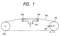
- Fig. 1 is a view which schematically shows the details of the conventional belt conveying mechanism as described above.
- a pair of platen rollers 140 are rotatively supported by a roller supporting member 141.
- the roller supporting member is arranged to be movable in the vertical direction (up and down).
- a conveying roller 120 is a driving roller driven by a driving mechanism (not shown). Meanwhile, a conveying roller 110 is a driven roller to rotate following the rotation of the driving roller 120 through a belt 130.
- the conveying roller 120 is fixed only to make its rotation possible.
- the conveying roller 110 is arranged to move in the direction to be further away from or closer to the conveying roller 120, that is, it is made possible to shift and rotate only in the horizontal direction to the left and right in Fig. 1. Also, the conveying roller 110 is biased by means of a tension adjustment spring 131 in the direction that it is further away from the conveying roller 120. In this way, an appropriate tension is exerted on the conveying belt 130.
- the belt conveying mechanism described above presents the following problems with respect to the gap adjustment required for an ink jet head serving as a printing head.
- the circumferential length of the belt 130 (the total length of the belt) tends to change (the tension often changes) by the movement of the platen rollers 140 if the platen rollers 140 are caused to shift up and down in order to adjust the gap between the ink jet head and a printing medium.
- the displacement of the adjustment spring 131 is only means for absorbing this change. Therefore, if such displacement becomes too great, the biasing force of the spring 131 is caused to increase, thus rather increasing the tension of the conveying belt 130 eventually. As a result, the belt 130 is caused to crack often or break in some cases.
- the conveying roller 110 on the upstream side is arranged to move horizontally. Therefore, it is difficult to parallel this roller with the conveying roller 120 precisely. Also, there is a problem that it is difficult to continuously maintain the parallel condition once set as it is. In such a case, the tension given to the belt becomes uneven so that the printing medium may be allowed to meander or take some irregular posture.
- the conveying roller 110 is movably arranged as described above, it is required to arrange a pressure roller that presses the printing medium to the conveying roller 110 to move following the movement of the conveying roller 110. Consequently, there is encountered a problem that the mechanism and others needed for the operation of these rollers also become more complicated.
- EP377339A shows a printing apparatus according to the preamble of claim 1.
- the present invention is designed in consideration of the problems described above. It is an object of the invention to provide a printing apparatus capable of making the tension exerted on an endless conveying member substantially constant even when the conveying surface of the endless conveying member is displaced.
- a second pressure member such as rollers to press the belt
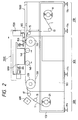
- Fig. 2 shows a printing apparatus useful for understanding the present invention.
- a reference numeral 1 designates cloth prepared as a printing medium.
- the cloth 1 is being fed out from the feeding roller 11 of a feeding unit 200 as the roller rotates, and wound up by a winding roller 21 through a conveying roller 17 and intermediate roller 19 after it is conveyed substantially in the horizontal direction by means of a conveying unit 100 arranged in the location facing a platen unit 1000 subsequent to being conveyed through intermediate rollers 13 and 15.
- the conveying unit 100 is provided with conveying rollers 110 and 120 arranged on the upstream and downstream sides of a printing unit 1000 roughly in the conveying direction of the cloth 1; a conveying belt 130 prepared in an endless mode rotatively arranged between these rollers; and a plurality of platen rollers 140 to cause the conveying belt 130 to be developed and tensioned appropriately in a given range in order to regulate and improve the flatness of the printing surface of the cloth.
- the conveying belt 130 used for the present embodiment is a metallic belt such as disclosed in Japanese Patent Laid-Open Application No. 5-212851, and as partially enlarged in Fig. 1 for representation, an adhesive layer (sheet) 133 is provided on the surface thereof. Then the cloth 1 is adhesively attached to the conveying belt 130 by means of the adhesive layer 133 and a fixing roller 150, thus securing its flatness at the time of printing.
- a carriage 1010 is installed on the printing unit 1000 movably in the direction perpendicular to the surface of Fig. 1 and Fig. 2. During the traveling period of the carriage 1010, printing is performed by means of two ink jet heads installed on the carriage.
- the cloth 1, being conveyed in a state where its flatness is thus secured, is provided with a printing agent by means of the printing unit 1000 while it is in the region between the platen rollers 140, and then, peeled off from the conveying belt 130 or the adhesive layer in the location where the conveying roller 120 is arranged.
- a drying treatment is given by means of a drying heater 600.
- the drying heater 600 is effective particularly when a liquid is used as a printing agent.
- the drying heater 600 it may be possible to adopt a device in such a mode as to blow hot air onto the cloth 1 or radiate infrared rays, among other appropriate means.
- a head shading station 1600 is arranged for the ink jet head 1010 in order to correct its density unevenness.
- the feed roller 11, the winding roller 21, the conveying rollers 110 and 120, and others are supported by a frame 113 and a side board 103 integrally arranged by a frame welding structure, which serve as the structural body of the textile printing apparatus.
- level pads 114 are provided in order to adjust the leveling of the apparatus in the horizontal and height directions with respect to the surface of the installation floor.
- the printing unit 1000 is installed movably in the horizontal direction to enhance the operativity of maintenance work or the like such as replacement of belts.
- Figs. 3A to 3C are views which illustrate the structural concept of the present embodiments, in which an upper platen roller 140U and a lower platen roller 140L are arranged, and a driving roller 120 and a driven roller 110 are fixed to the printing apparatus main body so that the distance between them is constantly maintained (1,160 mm). Also, the upper and lower platen rollers 140U and 140L are vertically movable, while maintaining the distance between them to be 180 mm.
- Fig. 3B illustrates its standard state.
- Fig. 3A illustrates a state where the upper and lower platen rollers 140U and 140L are displaced downward by 5 mm.
- Fig. 3C illustrates a state where the upper and lower platen rollers 140U and 140L are displaced upward by 5 mm.
- Figs. 4A to 4C illustrate the comparative example whose structure corresponds to the one in Fig. 1, in which no platen rollers are arranged on the lower side: only the upper platen rollers 140 are provided.
- Each of the other constituents is the same as the one shown in Figs. 3A to 3C.
- Fig. 4B shows a state where the platen rollers 140 are displaced downward by 5 mm
- Fig. 4C illustrates a state where the platen rollers 140 are displaced upward by 5 mm.
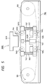
- Fig. 5, Fig. 6, and Fig. 7 are views showing the conveying unit in accordance with a first embodiment of the present invention. These are a side view, a view of this side observed from the back side, and a top view of the present embodiment, respectively.
- the axes of conveying rollers 110 and 120 are rotatively fixed to a side board 146. Therefore, the distance between the rollers is made constant (1,160 mm) as described earlier. At the same time, both rollers are adjusted in advance to be in parallel to each other. Also, the platen rollers 140U and 140L are rotatively supported by the respective supporting boards 141U and 141L in such a manner that these rollers are in parallel to the conveying rollers 110 and 120, respectively.
- a mechanism is arranged to cause the upper and lower platen rollers 140U and 140L to be interlocked and to maintain pitches as shown mainly in Fig. 5.
- a mechanism is arranged to displace the platen roller 140U upward or downward as shown mainly in Fig. 6.
- a ball screw supporting board 153 is fixed to the side board 146. Meanwhile, a ball screw 151 engages with the ball screw supporting board 153 through an angular bearing 154. At the same time, the ball screw is fixed to a worm wheel 156. The angular bearing 154 regulates the backlashes of the ball screw 151 in the thrust and radial directions. The other end of the ball screw 151 engages with a ball screw nut 152 fixed to a fixing plate 150 of the upper supporting board, which connects the upper platen supporting boards 141U arranged respectively on both side portions.
- Fig. 8 is a view which shows a state that the tension of the conveying belt (not shown in Fig. 8) is released in the conveying unit of the first embodiment described above.
- the supporting board 141L for the lower platen rollers is raised by means of the cylinder 143 in this released state. Also, it is possible to materialize lowering the supporting board 141U for the upper platen rollers by causing the worm wheel 156 to rotate.
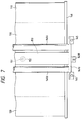
- Fig. 9 to Fig. 12 are views which illustrate the structure of a conveying unit in accordance with another embodiment of the present invention.
- Fig. 9 is a side view;
- Fig. 10 is a cross-sectional view;
- Fig. 11 is a top view;
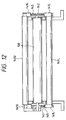
- Fig. 12 is a front view thereof observed from the conveying roller 120 side.
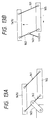
- the mechanism required for raising and lowering the supporting board 141U for the upper platen rollers is structured by use of parallel links.
- a fixed link 163 is fixed to a side board 146.
- the central portion of a movable link 162 is rotatively mounted.
- One end of this movable link 162 is rotatively mounted on the supporting board 141U for the upper platen rollers, while the other end is rotatively mounted on a slider 165.
- one end of the movable link 161 is rotatively mounted on the supporting board 141U for the upper platen rollers, while the other end is rotatively mounted on the slider 165.
- Figs. 13A and 13B show this linkage schematically.
- the slider 165 is guided by means of a linear guide bearing 170 and linear guide shaft 169 as shown mainly in Fig. 10, thus being arranged to shift in the left and right directions in Fig. 10.
- a ball nut 173 that engages with a ball screw 166 is mounted so that the slider 165 is shiftable in the left and right directions when the ball screw 160 rotates.
- both ends of the ball screw 166 are respectively installed on the supporting boards 171 and 172 on the upstream and downstream sides, which are fixed to the side board 146.
- a worm wheel 168 is mounted to engage with a worm gear 167.
- the worm gear 167 rotates manually through a handle 173 or by use of a motor 174.
- the shift of the slider 165 as described above is transformed into the vertical shift of the supporting board 141U for the upper platen rollers through the aforesaid linkage.
- the gap adjustment described above may be possible by controlling the rotation of the worm gear in accordance with the gap to be sensed by the gap sensor 144 shown in Fig. 5.
- Fig. 14 is a side view which shows a conveying unit in accordance with a third embodiment of the present invention.
- Conveying rollers 110 and 120 are rotatively mounted on the side board 146 in such a manner that the axes thereof are made parallel to each other. At the same time, it is structured so that the roller 110 on the driven side is caused to move further away from or closer to the roller 120 on the driving side, while maintaining the parallel condition between them, in order to conduct the initial setting of the belt 130 or the like.
- Each of three platen rollers 140U and 140L is rotatively mounted on a pair of supporting boards 201, which face each other, so that each of the rollers is in parallel to the conveying rollers 110 and 120.
- the three platen rollers 140U mounted on the supporting board 201 are arranged in such a manner that the conveying surface of the belt 130, being guided by these platen rollers 140U, is made extremely flat so as to preferably serve as the printing area for a printing medium.
- the pair of the supporting boards 201 are arranged to move vertically when an operator rotates a handle 202 to cause threaded shafts 206 to rotate, thus allowing each tooth portion provided for the respective shaft to engage with each tooth unit (not shown) mounted on the supporting board 201 through the rotational shaft 203, gears 204 and 205.
- shafts 207 are the members to support the side board 146 to a part 208 of the housing of the printing apparatus.
- the platen rollers 140U and 140L are caused to shift vertically while maintaining its positional relationship as it is.
- a printing apparatus for printing by use of a printing head on a printing medium to be conveyed by means of an endless conveying member 130 is provided with two rollers 110 and 120 that support the endless conveying member tensioned around them; a first displacement unit 104U to displace the portion of the endless conveying member that faces the printing head in the direction different from the traveling direction of the endless conveying member; and a second displacement unit 104L to displace the endless conveying member on the side opposite to the endless conveying member displaced by means of the first displacement member in accordance with the displacement of the endless conveying member caused by the first displacement member. Therefore, it is possible to make the tension exerted on the endless conveying member substantially constant even when the conveying surface of the endless conveying member is displaced.
- the gap between the ink jet head and a printing medium preferably for printing media of various thicknesses, while maintaining non-contacting state between them, by suppressing the amount of expansion or contraction of the endless conveying member in the conveying direction so as to exert a substantially constant tension on the endless conveying member even when changing the gap between the printing head and the conveying surface of the endless conveying member.
- a metallic belt or a rubber belt that is not easy to be deformed elastically should be employed. Therefore, in accordance with each of the embodiments described above, it is arranged so that the amount of expansion or contraction of the belt material is small when the head gap is adjusted, thus making it easier to select a belt material that is preferably used for the maintenance of the surface that provides a specific area in the printing region.
- the printed cloth is dried (including natural drying). Subsequently, the dyes on fiber texture are diffused, and then, a step is taken to cause the dyes to react and fix them on the cloth. In this step, it is possible to obtain both a sufficient coloring and durability by the fixation of dyes.
- the present invention preprocess the cloth as required.
- cloth provided with a layer for receiving ink.
- reduction preventive agent or alkaline substance is contained.
- alkaline substance it is possible to cite, for example, sodium hydroxide, potassium hydroxide, or other sodium alkaline metals, mono-, di-, tri-ethanol amine or other amine group, sodium carbonate, sodium bicarbonate, or other carbonates, alkaline metallic bicarbonate salt or the like.
- organic metallic salt such as calcium acetate, barium acetate, or ammonia and ammonia compound or the like.
- trichloro natrium acetate or the like that is transformed into alkaline substance by the application of steaming and drying heat. Particularly, preference is given to natrium carbonate and natrium bicarbonate as an alkaline substance, which is usable as a dye color of reactive pigment.
- water soluble polymer there can be cited, for example, starch such as corn, wheat, cellulose substance such as carboxymethyl cellulose, methyl cellulose, hydroxyethyl cellulose, polysaccharide such as natrium alginic acid, arabian rubber, loquasweet bean rubber, tragacanth rubber, guam rubber, and tamarind seed, protein substance such as gelatin, casein, and water soluble natural polymer such as tannic substance and lignin substance.
- starch such as corn, wheat, cellulose substance such as carboxymethyl cellulose, methyl cellulose, hydroxyethyl cellulose, polysaccharide such as natrium alginic acid, arabian rubber, loquasweet bean rubber, tragacanth rubber, guam rubber, and tamarind seed
- protein substance such as gelatin, casein
- water soluble natural polymer such as tannic substance and lignin substance.
- synthetic polymer there can be cited, for example, polyvinyl alcoholic compound, polyethylene oxide compound, alkali acid water soluble polymer, maleic anhydride water soluble polymer or the like. Of these substances, it is preferable to use polysaccharide polymer or cellulose polymer.
- water soluble metallic salt there can be cited, for example, alkali metals or a compound of pH4 to 10, which forms typical ionic crystals, such as halogenous compound of alkaline earth metals.
- alkali metals or a compound of pH4 to 10 which forms typical ionic crystals, such as halogenous compound of alkaline earth metals.
- typical examples of such compounds there can be cited NaCl, Na 2 SO 4 , KCl and CH 3 COONa, or the like.
- alkaline earth metals CaCl 2 and MgCl 2 or the like. Of these substances, salt group such as Na, K and Ca are preferable.
- the methods for enabling cloth to contain those substances and others are not particularly limited. It may be possible to adopt a usually performed dipping method, a padding method, a coating method, or a spraying method, among others.
- the textile printing ink which is applicable to cloth for use of ink jet printing, is such as just adhering to the cloths when it is applied to printing on the cloths. Therefore, it is preferable to execute a fixing process so that the color pigments in ink such as dyes should be fixed to the cloths.
- a fixing process of the kind any one of known methods is usable. For example, a steaming method, an HT steaming method, or a thermofixing method may be cited. If no alkali treatment is given to them in advance, there can be cited an alkali pad steaming method, an alkali blotch steaming method, an alkali shock method, an alkali cold fixing method, among others.
- the fixing process there are those which include a reaction process or do not include it depending on the dyes to be used.
- the dyes are contained in the cloths and do not allow them to be removed physically.
- ink it is possible to use any one of them appropriately if only a required pigment is contained.
- ink containing colors not necessarily dyes.
- rinsing may be applied in accordance with the conventionally know method after having executed the reactive fixation as described above. In this respect, it is preferable to perform the conventional fixing process together when exercising the rinsing treatment.
- the printed articles that have been given the post processes as described above are cut in a desired size.
- Each of the pieces thus cut is processed in order to make it a final product, such as by means of sewing, bonding, welding, or the like, thus obtaining one-piece, dress, necktie, swim suit or other clothing, or bed cover, sofa cover, handkerchief, curtain, or the like.
- the method for processing cloths to make them clothing or other daily necessities by means of sawing and others is disclosed in many books publicly known, such as “Modern Netting and Machining Manual (Published by Seni Journal Inc.)” and “Monthly Magazine, Souen (Published by Bunka Shuppan Kyoku)", among others.
- the cloths include all the textiles, nonwoven textiles, and other cloths irrespective of materials, weaving and netting methods.
- the present invention it is possible to employ not only the aforesaid ink jet printing method, but also various printing methods.
- an ink jet printing method to embody the present invention significant effects are obtainable.
- the adoption of an ink jet printing method to embody the present invention it is possible to demonstrate particularly excellent effects by the application of a method having means for generating thermal energy to be utilized as energy for discharging ink, which is capable of changing states of ink when the thermal energy is applied.
- the adoption of printing head and apparatus using the bubble jet method advocated by Canon Inc. contributes to obtaining still better results.
- a method of the kind printing is possible in a higher density and precision.
- the method is suitable for the on-demand type because the principle is such that at least one driving signal, which provides a rapid temperature rise beyond a departure from nucleation boiling point in response to printing information, is applicable to an electrothermal transducer disposed on a liquid (ink) retaining sheet or liquid passage whereby to cause the electrothermal transducer to generate thermal energy to produce film boiling on the thermoactive portion of printing head, thus effectively leading to the resultant formation of a bubble in the liquid (ink) one to one for each of the driving signals.
- the liquid (ink) is discharged through a discharging port to produce at least one droplet.
- the driving signal is more preferably in the form of pulses because the development and contraction of the bubble can be effectuated instantaneously, and, therefore, the liquid (ink) is discharged with quick response.
- the driving signal in the form of pulses is preferably such as disclosed in the specifications of U.S. Patent Nos. 4,463,359 and 4,345,262.
- the temperature increasing rate of the heating surface is preferably such as disclosed in the specification of U.S. Patent No. 4,313,124 for an excellent printing in a better condition.
- the structure of the printing head may be as shown in each of the above-mentioned specifications wherein the structure is arranged to combine the discharging ports, liquid passages, and the electrothermal transducers (linear type liquid passages or right-angled liquid passages).
- the structure such as disclosed in the specifications of U.S. Patent Nos. 4,558,333 and 4,459,600 wherein the thermal activation portions are arranged in a curved area is also included in the present invention.
- the present invention is effectively applicable to the structure disclosed in Japanese Patent Laid-Open Application No. 59-123670 wherein a common slit is used as the discharging ports for plural electrothermal transducers, and to the structure disclosed in Japanese Patent Laid-Open Application No. 59-138461 wherein an aperture for absorbing pressure wave of the thermal energy is formed corresponding to the discharge ports.
- Japanese Patent Laid-Open Application No. 59-138461 wherein an aperture for absorbing pressure wave of the thermal energy is formed corresponding to the discharge ports.
- the printing head in accordance with the mode of a printing apparatus.
- the mode of the so-called line printer it should be good enough if only the printing head is structured so that its discharge ports are arranged over an area corresponding to the width of a printing medium.
- the present invention is effectively applicable to a printing head fixed to the apparats main body or to an exchangeable chip type, which can be electrically connected with the apparatus main body and ink is supplied from the apparatus main body to the head when it is installed in the apparatus main body, or to the printing head of a cartridge type in which an ink tank is formed together with the printing head itself.
- a printing head with recovery means and preliminarily auxiliary means as constituents of the printing apparatus because these additional means will contribute to making the effectiveness of the present invention more stabilized.
- these additional means are capping means for the printing head, cleaning means, compression or suction means, preliminary heating means using electrothermal transducing elements or heating elements other than these transducing elements or combination of both elements, and predischarge means for executing discharges other than those for printing.
- the ink may be an ink material which is solidified below the room temperature but liquefied at the room temperature. Since the ink is controlled within the temperature not lower than 30°C and not higher than 70°C to stabilize its viscosity for the provision of the stable discharge in general for an ink jet method, the ink may be such as to be liquefied when the applicable printing signals are given.
- ink having a nature of being liquefied only by the application of heat so as to positively prevent the temperature from rising due to the thermal energy by use of such energy as an energy to be consumed for changing states of ink from solid to liquid, or to prevent ink from being evaporated by use of the ink which will be solidified when left intact.
- thermal energy such as the ink, which is capable of being discharged as ink liquid by enabling itself to be liquefied when the thermal energy is applied in accordance with printing signals, and the ink, which will have already begun solidifying itself by the time it reaches a printing medium.
- ink in the form of liquid or solid in the recesses or through holes of a porous sheet such as disclosed in Japanese Patent Laid-Open Application No. 54-56847 or 60-71260 in order to enable ink to face the electrothermal transducers.
- the most effective method adoptable for the various kinds of ink referred to above is the one which is capable of implementing film boiling as described above.
Landscapes
- Engineering & Computer Science (AREA)
- Textile Engineering (AREA)
- Chemical & Material Sciences (AREA)
- Materials Engineering (AREA)
- Ink Jet (AREA)
- Handling Of Sheets (AREA)
- Coloring (AREA)
Claims (14)
- Druckgerät zum Drucken unter Verwendung eines Druckkopfes auf einem Druckmedium (1), das mittels eines endlosen Förderelementes (130) befördert wird, mit:zwei Rollenelementen (110, 120) zum Stützen des endlosen Förderelementes, das um sie herum gespannt ist,einer ersten Verschiebeeinheit (140U; 141U) zum Verschieben eines ersten Abschnittes des endlosen Förderelementes (130), der dem Druckkopf zugewandt ist, in einer quer zu der Laufrichtung des ersten Abschnittes des endlosen Förderelementes verlaufenden Richtung, undeiner zweiten Verschiebeeinheit (140L; 141L) zum Verschieben eines zweiten Abschnittes des endlosen Förderelementes an der Seite, die zu dem ersten Abschnitt des endlosen Förderelementes entgegengesetzt ist, das durch die erste Verschiebeeinheit (140U; 141U) verschoben wurde, in einer zu der Laufrichtung des zweiten Abschnittes quer verlaufenden Richtung,
dadurch gekennzeichnet, daßdie zweite Verschiebeeinheit (140L; 141L) derart aufgebaut ist, daß sie die Verschiebung zusammen mit der ersten Verschiebeeinheit ausführt, während der Abstand zwischen den Verschiebeeinheiten im wesentlichen konstant gehalten wird. - Druckgerät gemäß Anspruch 1, wobei
die erste Verschiebeeinheit (141U) und die zweite Verschiebeeinheit (141L) elastisch verbunden sind. - Druckgerät gemäß Anspruch 1, wobei
die erste Verschiebeeinheit (140U) und die zweite Verschiebeeinheit (140L) mittels eines Tafelelementes (201) verbunden sind. - Druckgerät gemäß Anspruch 2, wobeidas endlose Förderelement ein Riemen (130) ist und die erste Verschiebeeinheit (141U) eine Drück-Einrichtung (151-157) zum Drücken des Riemens aufweist, um den Riemen zu verschieben.
- Druckgerät gemäß Anspruch 4, wobei
die Drück-Einrichtung (151-157) eine Verschiebung erzeugt, um den Zwischenraum zwischen dem Druckkopf und einem Druckmedium, das durch den Riemen (130) gefördert wird, einzustellen. - Druckgerät gemäß Anspruch 4, wobei
die erste Verschiebeeinheit (140U; 141U) und die zweite Verschiebeeinheit (140L; 141L) Elemente der Rollenbauart aufweisen. - Druckgerät gemäß Anspruch 4, wobei
die Elemente der Rollenbauart jeweils eine Vielzahl an Rollen sind. - Druckgerät gemäß einem der Ansprüche 1 bis 7, wobei
das Druckmedium ein Textilerzeugnis ist. - Druckgerät gemäß einem der Ansprüche 1 bis 8, wobei
der Druckkopf durch ein Ausstoßen von Tinte druckt. - Druckgerät gemäß Anspruch 9, wobei
der Druckkopf ein Tintenstrahldruckkopf zum Ausstoßen von Tinte aus Tintenausstoßöffnungen ist. - Druckgerät gemäß Anspruch 10, wobei
der Druckkopf ein Tintenstrahldruckkopf ist, der mit elektrothermischen Wandlerelementen zum Ausstoßen von Tinte aus Tintenausstoßöffnungen durch von den elektrothermischen Wandlerelementen erzeugte Wärmeenergie ist. - Druckgerät gemäß Anspruch 10, wobei
eine Vielzahl an ersten Verschiebeeinheiten entlang der Förderrichtung des Aufzeichnungsmediums und einer Stützfläche des endlosen Förderelementes (130), das einem Druckkopf gegenüber steht, vorgesehen sind, um das Aufzeichnungsmedium zwischen den ersten Verschiebeeinheiten zu stützen. - Druckgerät gemäß Anspruch 1, wobei
ein Abstand zwischen den beiden Rollenelementen (110, 120) und ein Abstand zwischen den jeweils durch die erste und die zweite Verschiebeeinheit (140U, 140L) des endlosen Förderelementes, die einander gegenüber stehen, gestützten Orten konstant sind. - Druckgerät gemäß Anspruch 1, wobei
ein Abstand zwischen dem Druckkopf (1000) und einem Ort des endlosen Förderelementes (130), der dem Druckkopf gegenüber steht, in Übereinstimmung mit der Dicke des Druckmediums durch die Bewegung der ersten und der zweiten Verschiebeeinheit variabel ist.
Applications Claiming Priority (4)
| Application Number | Priority Date | Filing Date | Title |
|---|---|---|---|
| JP244421/94 | 1994-10-07 | ||
| JP24442194 | 1994-10-07 | ||
| JP7249967A JPH08156353A (ja) | 1994-10-07 | 1995-09-27 | プリント装置 |
| JP249967/95 | 1995-09-27 |
Publications (2)
| Publication Number | Publication Date |
|---|---|
| EP0705707A1 EP0705707A1 (de) | 1996-04-10 |
| EP0705707B1 true EP0705707B1 (de) | 1999-03-24 |
Family
ID=26536732
Family Applications (1)
| Application Number | Title | Priority Date | Filing Date |
|---|---|---|---|
| EP95115802A Expired - Lifetime EP0705707B1 (de) | 1994-10-07 | 1995-10-06 | Druckgerät |
Country Status (6)
| Country | Link |
|---|---|
| US (1) | US5854643A (de) |
| EP (1) | EP0705707B1 (de) |
| JP (1) | JPH08156353A (de) |
| KR (1) | KR100202725B1 (de) |
| CN (1) | CN1060116C (de) |
| DE (1) | DE69508515T2 (de) |
Families Citing this family (69)
| Publication number | Priority date | Publication date | Assignee | Title |
|---|---|---|---|---|
| US6386662B1 (en) * | 1997-02-03 | 2002-05-14 | Citicorp Development Center, Inc. | Wide mouth banking depositor |
| US6013347A (en) * | 1997-07-16 | 2000-01-11 | 3M Innovative Properties Company | Method of continuous tone imaging to provide an imaged high loft mat product |
| US6394596B1 (en) | 1999-10-05 | 2002-05-28 | Hewlett-Packard Company | Belt-type media support for a printer |
| US6652054B2 (en) | 2000-02-01 | 2003-11-25 | Aprion Digital Ltd. | Table and a motion unit for adjusting the height thereof |
| EP1780028B1 (de) * | 2000-02-23 | 2008-06-04 | Agfa Graphics N.V. | Tintenstrahldrucker mit Vorrichtung zum Vermeiden unerwünschter seitlicher Bandbewegung |
| US6588954B2 (en) * | 2000-02-23 | 2003-07-08 | Agfa-Gevaert | Ink jet printer equipped for avoiding undesired belt movement |
| JP4278885B2 (ja) * | 2000-05-25 | 2009-06-17 | 富士フイルム株式会社 | インクジェットプリンタ |
| US6755518B2 (en) * | 2001-08-30 | 2004-06-29 | L&P Property Management Company | Method and apparatus for ink jet printing on rigid panels |
| US6523921B2 (en) | 2000-08-30 | 2003-02-25 | L&P Property Management | Method and apparatus for printing on rigid panels and other contoured or textured surfaces |
| US6406110B1 (en) | 2000-09-01 | 2002-06-18 | Lexmark International, Inc | Mechanism to automate adjustment of printhead-to-print medium gap spacing on an imaging apparatus |
| IT1316139B1 (it) * | 2000-09-15 | 2003-03-28 | Durst Phototechnik Ag | Dispositivo di stampa a getto di inchiostro. |
| US6561607B1 (en) * | 2000-10-05 | 2003-05-13 | Eastman Kodak Company | Apparatus and method for maintaining a substantially constant closely spaced working distance between an inkjet printhead and a printing receiver |
| AU2002212650A1 (en) * | 2000-10-23 | 2002-05-06 | Aprion Digital Ltd. | A table and a motion unit for adjusting the height thereof |
| JP2002283636A (ja) * | 2001-03-27 | 2002-10-03 | Sony Corp | プリンター |
| US20030116041A1 (en) * | 2001-12-20 | 2003-06-26 | Delaware Capital Formation, Inc. | Moveable idler carriage for support of a web in relation to an array of inkjet printing devices |
| US6840617B2 (en) * | 2002-04-02 | 2005-01-11 | Lexmark International, Inc. | Mid-frame for an imaging apparatus |
| US6938894B2 (en) * | 2002-12-19 | 2005-09-06 | Pitney Bowes Inc. | Transport mechanism and method for a mailing machine |
| US7118103B2 (en) * | 2003-04-14 | 2006-10-10 | Heidelberger Druckmaschinen Ag | Device for conveying sheets through a printing machine |
| JP2005014343A (ja) * | 2003-06-25 | 2005-01-20 | Roland Dg Corp | インクジェットプリンタ |
| JP4321151B2 (ja) * | 2003-07-23 | 2009-08-26 | 沖電気工業株式会社 | プリンタ |
| JP2005096280A (ja) | 2003-09-25 | 2005-04-14 | Konica Minolta Holdings Inc | インクジェット記録装置 |
| EP1529648A1 (de) * | 2003-11-08 | 2005-05-11 | Atlantic ZeiserGmbH | Verfahren zur Herstellung von Informationsträgern, z.B. von Karten, und Einrichtung zur Durchführung |
| US7325895B2 (en) * | 2004-03-26 | 2008-02-05 | Brother Kogyo Kabushiki Kaisha | Printer |
| JP4539399B2 (ja) * | 2004-03-26 | 2010-09-08 | ブラザー工業株式会社 | 記録装置 |
| US7422386B2 (en) * | 2004-07-07 | 2008-09-09 | Roland Dg Corporation | Image creation and cutting apparatus |
| US20060238815A1 (en) * | 2005-04-21 | 2006-10-26 | The Boeing Company | Systems and methods of reproducing images onto surfaces |
| US8493628B2 (en) * | 2005-04-21 | 2013-07-23 | The Boeing Company | Reproduction of images onto surfaces |
| KR20060123842A (ko) * | 2005-05-30 | 2006-12-05 | 삼성전자주식회사 | 잉크 토출장치와 이를 포함하는 화상형성장치 및 화상 형성방법 |
| KR100789230B1 (ko) | 2006-05-17 | 2008-01-02 | 주식회사 디지아이 | 플로터의 원단 장력조절 장치 |
| US20090160889A1 (en) * | 2007-12-24 | 2009-06-25 | Pitney Bowes Inc. | Method and apparatus for printing on variable thickness print media |
| JP5009817B2 (ja) * | 2008-01-08 | 2012-08-22 | 株式会社リコー | 画像形成装置 |
| EP2106916B1 (de) * | 2008-03-31 | 2011-05-04 | Dainippon Screen Mfg., Co., Ltd. | Bildaufzeichnungsvorrichtung |
| JP5193738B2 (ja) * | 2008-08-15 | 2013-05-08 | 理想科学工業株式会社 | インクジェット記録装置 |
| JP5513727B2 (ja) | 2008-10-01 | 2014-06-04 | 株式会社ミヤコシ | 布帛の捺染方法及びその装置 |
| JP5274977B2 (ja) * | 2008-10-24 | 2013-08-28 | 株式会社ミヤコシ | インクジェット記録装置 |
| JP5384215B2 (ja) * | 2009-06-16 | 2014-01-08 | 株式会社ミマキエンジニアリング | プリンタ装置 |
| JP5568333B2 (ja) * | 2010-02-24 | 2014-08-06 | 理想科学工業株式会社 | 画像記録装置 |
| JP5646866B2 (ja) * | 2010-03-31 | 2014-12-24 | キヤノン株式会社 | 媒体搬送装置 |
| CN101973166A (zh) * | 2010-08-18 | 2011-02-16 | 温州品正电器有限公司 | 一种布料印刷机 |
| CN102582214B (zh) * | 2012-03-20 | 2013-07-31 | 丹东金丸集团有限公司 | 纳米材料直接制版机喷头组合装置 |
| US9044928B2 (en) * | 2012-04-12 | 2015-06-02 | R.R. Donnelley & Sons Company | Mailing lines and related methods |
| US9365061B2 (en) * | 2014-02-11 | 2016-06-14 | Electronics For Imaging, Inc. | External table height adjustment for printer systems |
| JP6222464B2 (ja) * | 2014-02-25 | 2017-11-01 | セイコーエプソン株式会社 | 液体吐出装置及び媒体の前処理方法 |
| JP5762585B1 (ja) * | 2014-02-27 | 2015-08-12 | 三菱重工印刷紙工機械株式会社 | 印刷装置 |
| JP6364989B2 (ja) * | 2014-06-18 | 2018-08-01 | セイコーエプソン株式会社 | 記録装置 |
| JP2016037682A (ja) * | 2014-08-08 | 2016-03-22 | 株式会社ミマキエンジニアリング | テキスタイルプリント装置 |
| CN104139616B (zh) * | 2014-08-08 | 2016-04-13 | 湖州巧布师数码科技有限公司 | 一种用于宽幅数码印花涤纶墙布的传送装置 |
| JP6582624B2 (ja) * | 2014-09-08 | 2019-10-02 | セイコーエプソン株式会社 | 記録装置 |
| JP6701899B2 (ja) * | 2016-04-05 | 2020-05-27 | セイコーエプソン株式会社 | 液体吐出装置及び媒体の押さえ方法 |
| CN107471841A (zh) * | 2017-09-15 | 2017-12-15 | 湖州博润实业有限公司 | 一种纺织品全自动印花装置 |
| CN107458081A (zh) * | 2017-09-15 | 2017-12-12 | 湖州博润实业有限公司 | 一种纺织品印花工作机 |
| CN107620180B (zh) * | 2017-11-02 | 2020-04-24 | 界首市永顺服饰有限公司 | 一种用于服装生产的布料印染装置 |
| EP3489022B1 (de) | 2017-11-22 | 2020-09-02 | Frama AG | Einrichtung zum bedrucken von einem druckwerk einzeln zugeführten versandstücken |
| CN108044923B (zh) * | 2017-12-20 | 2023-12-19 | 常州丰盛光电科技股份有限公司 | 表面结构可更换的复合辊筒模具及其制造工艺 |
| KR102193013B1 (ko) * | 2018-06-22 | 2020-12-18 | 김동철 | Uv잉크 인쇄유닛을 이용하여 투명글라스에 문양을 인쇄하는 방법 |
| CN108859402A (zh) * | 2018-06-28 | 2018-11-23 | 湖州新天地印刷有限公司 | 一种纸筒纸板环保印刷的压紧装置 |
| JP7119756B2 (ja) * | 2018-08-21 | 2022-08-17 | コニカミノルタ株式会社 | 捺染インクジェットプリンタ |
| CN109177527A (zh) * | 2018-08-23 | 2019-01-11 | 合肥海闻自动化设备有限公司 | 平板打印机除静电系统 |
| JP7309402B2 (ja) * | 2019-03-26 | 2023-07-18 | 理想科学工業株式会社 | 画像形成装置 |
| JP7383950B2 (ja) | 2019-09-20 | 2023-11-21 | コニカミノルタ株式会社 | 画像形成装置 |
| WO2021066832A1 (en) * | 2019-10-03 | 2021-04-08 | Hewlett-Packard Development Company, L.P. | Printhead to print medium spacing adjusting system |
| US20230158813A1 (en) * | 2020-04-23 | 2023-05-25 | Hewlett-Packard Development Company, L.P. | Adjusting distance between print media and printhead |
| CN111923609A (zh) * | 2020-08-20 | 2020-11-13 | 吕学兴 | 一种新型文具标签生产设备 |
| CN112208196A (zh) * | 2020-09-16 | 2021-01-12 | 马鞍山虹润彩印有限责任公司 | 一种绿色环保的食品包装膜印刷专用印刷机构 |
| JP2022148081A (ja) * | 2021-03-24 | 2022-10-06 | セイコーエプソン株式会社 | 印刷装置及び印刷方法 |
| NL2032611B1 (en) * | 2022-07-27 | 2024-02-05 | Canon Kk | A printer with a definition roller for an endless belt |
| WO2024247810A1 (ja) * | 2023-05-30 | 2024-12-05 | 京セラ株式会社 | インクジェット記録装置 |
| EP4610054A1 (de) * | 2024-02-29 | 2025-09-03 | Ricoh Company, Ltd. | Bilderzeugungsgerät |
| CN120396531B (zh) * | 2025-07-01 | 2025-08-29 | 汇精(厦门)电子科技有限公司 | 一种关于膜材动态传输过程喷码装置 |
Family Cites Families (23)
| Publication number | Priority date | Publication date | Assignee | Title |
|---|---|---|---|---|
| CA1127227A (en) * | 1977-10-03 | 1982-07-06 | Ichiro Endo | Liquid jet recording process and apparatus therefor |
| JPS5936879B2 (ja) * | 1977-10-14 | 1984-09-06 | キヤノン株式会社 | 熱転写記録用媒体 |
| US4330787A (en) * | 1978-10-31 | 1982-05-18 | Canon Kabushiki Kaisha | Liquid jet recording device |
| US4207579A (en) * | 1979-01-08 | 1980-06-10 | The Mead Corporation | Reciprocating paper handling apparatus for use in an ink jet copier |
| US4345262A (en) * | 1979-02-19 | 1982-08-17 | Canon Kabushiki Kaisha | Ink jet recording method |
| US4463359A (en) * | 1979-04-02 | 1984-07-31 | Canon Kabushiki Kaisha | Droplet generating method and apparatus thereof |
| US4313124A (en) * | 1979-05-18 | 1982-01-26 | Canon Kabushiki Kaisha | Liquid jet recording process and liquid jet recording head |
| US4558333A (en) * | 1981-07-09 | 1985-12-10 | Canon Kabushiki Kaisha | Liquid jet recording head |
| JPS59123670A (ja) * | 1982-12-28 | 1984-07-17 | Canon Inc | インクジエツトヘツド |
| JPS59138461A (ja) * | 1983-01-28 | 1984-08-08 | Canon Inc | 液体噴射記録装置 |
| JPS6071260A (ja) * | 1983-09-28 | 1985-04-23 | Erumu:Kk | 記録装置 |
| JPS6253492A (ja) * | 1985-08-29 | 1987-03-09 | キヤノン株式会社 | 捺染方法 |
| US4620807A (en) * | 1985-09-23 | 1986-11-04 | Xerox Corporation | Article transport for printers |
| JPS62149469A (ja) * | 1985-12-24 | 1987-07-03 | Matsushita Electric Ind Co Ltd | 印字装置 |
| JPH0213172A (ja) * | 1988-06-30 | 1990-01-17 | Tokyo Electric Co Ltd | イメージスキヤナの原稿送り装置 |
| JPH02182641A (ja) * | 1988-12-30 | 1990-07-17 | Canon Inc | 画像記録装置 |
| US5280308A (en) * | 1989-02-23 | 1994-01-18 | Canon Kabushiki Kaisha | Sheet feeding device |
| JPH0346589A (ja) * | 1989-07-13 | 1991-02-27 | Mitsubishi Electric Corp | 測距装置 |
| JP2816217B2 (ja) * | 1990-02-21 | 1998-10-27 | キヤノン株式会社 | 記録装置 |
| JPH05147207A (ja) * | 1991-11-30 | 1993-06-15 | Mita Ind Co Ltd | インクジエツトプリンタ |
| JP2736484B2 (ja) * | 1992-02-05 | 1998-04-02 | 鐘紡株式会社 | 捺染装置 |
| JPH06220781A (ja) * | 1993-01-28 | 1994-08-09 | Kanebo Ltd | 捺染方法および装置 |
| JP3046589U (ja) | 1997-08-26 | 1998-03-10 | 株式会社三栄マシニング | モンキ−スパナ− |
-
1995
- 1995-09-27 JP JP7249967A patent/JPH08156353A/ja active Pending
- 1995-10-04 US US08/539,220 patent/US5854643A/en not_active Expired - Lifetime
- 1995-10-06 EP EP95115802A patent/EP0705707B1/de not_active Expired - Lifetime
- 1995-10-06 CN CN95119173A patent/CN1060116C/zh not_active Expired - Fee Related
- 1995-10-06 DE DE69508515T patent/DE69508515T2/de not_active Expired - Lifetime
- 1995-10-07 KR KR1019950034434A patent/KR100202725B1/ko not_active Expired - Fee Related
Also Published As
| Publication number | Publication date |
|---|---|
| KR100202725B1 (ko) | 1999-06-15 |
| EP0705707A1 (de) | 1996-04-10 |
| DE69508515T2 (de) | 1999-09-16 |
| KR960013682A (ko) | 1996-05-22 |
| DE69508515D1 (de) | 1999-04-29 |
| JPH08156353A (ja) | 1996-06-18 |
| CN1060116C (zh) | 2001-01-03 |
| CN1133788A (zh) | 1996-10-23 |
| US5854643A (en) | 1998-12-29 |
Similar Documents
| Publication | Publication Date | Title |
|---|---|---|
| EP0705707B1 (de) | Druckgerät | |
| US6068374A (en) | Image forming apparatus | |
| US6267518B1 (en) | Ink-jet printing apparatus and ink-jet printing method | |
| US6024441A (en) | Image forming apparatus | |
| EP0714779B1 (de) | Tintenstrahldruckgerät | |
| US6932454B2 (en) | Image recording apparatus and method for recording an image on a recording medium | |
| CA2154208C (en) | Recording apparatus for performing complementary recording and recording method therefor | |
| EP0700790B1 (de) | Druckvorrichtung und Verfahren zur Steuerung der Druckkopftemperatur in einer solchen Druckvorrichtung | |
| US5541626A (en) | Recording apparatus and method for manufacturing recorded product thereby | |
| JP3118153B2 (ja) | 液体噴射装置およびこれを用いた捺染システム | |
| US6257697B1 (en) | Fluid ejecting apparatus, a print system, a method of recovering fluid from a fluid ejecting head, and a record product all including a wiping blade for wiping an ejection surface | |
| US6017111A (en) | Ink jet recording apparatus with device for exhausting ink mist | |
| JP3286059B2 (ja) | 画像形成装置、該装置用搬送ベルトの着脱装置および方法 | |
| JP3501599B2 (ja) | 記録装置および吐出不良の検出方法 | |
| JPH08108588A (ja) | インクジェットプリント装置 | |
| JP3459125B2 (ja) | インクジェット・プリンタにおけるプリントヘッド−媒体間距離の適応制御 | |
| US7222933B2 (en) | Inkjet recording apparatus and recovery control after interruption of its recording operation | |
| JPH08108530A (ja) | インクジェットプリント装置 | |
| JPH07214767A (ja) | インクジェットプリント装置 | |
| US5771049A (en) | Fluid-jet recording apparatus and method in which fluid-jet head heating is controlled | |
| JPH07214865A (ja) | 画像形成装置 | |
| JP3630886B2 (ja) | インク供給装置および該装置を用いるインクジェットプリント装置 | |
| EP3332974B1 (de) | Druckverfahren und druckvorrichtung | |
| JPH11192691A (ja) | インクジェットプリント装置 | |
| JPH08108531A (ja) | インクジェットプリント装置 |
Legal Events
| Date | Code | Title | Description |
|---|---|---|---|
| PUAI | Public reference made under article 153(3) epc to a published international application that has entered the european phase |
Free format text: ORIGINAL CODE: 0009012 |
|
| AK | Designated contracting states |
Kind code of ref document: A1 Designated state(s): DE FR GB IT |
|
| 17P | Request for examination filed |
Effective date: 19960828 |
|
| 17Q | First examination report despatched |
Effective date: 19961025 |
|
| GRAG | Despatch of communication of intention to grant |
Free format text: ORIGINAL CODE: EPIDOS AGRA |
|
| GRAG | Despatch of communication of intention to grant |
Free format text: ORIGINAL CODE: EPIDOS AGRA |
|
| GRAG | Despatch of communication of intention to grant |
Free format text: ORIGINAL CODE: EPIDOS AGRA |
|
| GRAH | Despatch of communication of intention to grant a patent |
Free format text: ORIGINAL CODE: EPIDOS IGRA |
|
| GRAH | Despatch of communication of intention to grant a patent |
Free format text: ORIGINAL CODE: EPIDOS IGRA |
|
| GRAA | (expected) grant |
Free format text: ORIGINAL CODE: 0009210 |
|
| AK | Designated contracting states |
Kind code of ref document: B1 Designated state(s): DE FR GB IT |
|
| REF | Corresponds to: |
Ref document number: 69508515 Country of ref document: DE Date of ref document: 19990429 |
|
| ET | Fr: translation filed | ||
| ITF | It: translation for a ep patent filed | ||
| PLBE | No opposition filed within time limit |
Free format text: ORIGINAL CODE: 0009261 |
|
| STAA | Information on the status of an ep patent application or granted ep patent |
Free format text: STATUS: NO OPPOSITION FILED WITHIN TIME LIMIT |
|
| 26N | No opposition filed | ||
| REG | Reference to a national code |
Ref country code: GB Ref legal event code: IF02 |
|
| PGFP | Annual fee paid to national office [announced via postgrant information from national office to epo] |
Ref country code: IT Payment date: 20081020 Year of fee payment: 14 |
|
| PGFP | Annual fee paid to national office [announced via postgrant information from national office to epo] |
Ref country code: FR Payment date: 20081024 Year of fee payment: 14 |
|
| REG | Reference to a national code |
Ref country code: FR Ref legal event code: ST Effective date: 20100630 |
|
| PG25 | Lapsed in a contracting state [announced via postgrant information from national office to epo] |
Ref country code: FR Free format text: LAPSE BECAUSE OF NON-PAYMENT OF DUE FEES Effective date: 20091102 |
|
| PG25 | Lapsed in a contracting state [announced via postgrant information from national office to epo] |
Ref country code: IT Free format text: LAPSE BECAUSE OF NON-PAYMENT OF DUE FEES Effective date: 20091006 |
|
| PGFP | Annual fee paid to national office [announced via postgrant information from national office to epo] |
Ref country code: DE Payment date: 20131031 Year of fee payment: 19 Ref country code: GB Payment date: 20131018 Year of fee payment: 19 |
|
| REG | Reference to a national code |
Ref country code: DE Ref legal event code: R119 Ref document number: 69508515 Country of ref document: DE |
|
| GBPC | Gb: european patent ceased through non-payment of renewal fee |
Effective date: 20141006 |
|
| PG25 | Lapsed in a contracting state [announced via postgrant information from national office to epo] |
Ref country code: GB Free format text: LAPSE BECAUSE OF NON-PAYMENT OF DUE FEES Effective date: 20141006 Ref country code: DE Free format text: LAPSE BECAUSE OF NON-PAYMENT OF DUE FEES Effective date: 20150501 |