EP0677749A2 - Procédé et dispositif de détection d'anomalie, et système générateur d'énergie électrique l'utilisant - Google Patents
Procédé et dispositif de détection d'anomalie, et système générateur d'énergie électrique l'utilisant Download PDFInfo
- Publication number
- EP0677749A2 EP0677749A2 EP95302507A EP95302507A EP0677749A2 EP 0677749 A2 EP0677749 A2 EP 0677749A2 EP 95302507 A EP95302507 A EP 95302507A EP 95302507 A EP95302507 A EP 95302507A EP 0677749 A2 EP0677749 A2 EP 0677749A2
- Authority
- EP
- European Patent Office
- Prior art keywords
- solar cell
- photoelectric conversion
- conversion element
- abnormality
- comparing
- Prior art date
- Legal status (The legal status is an assumption and is not a legal conclusion. Google has not performed a legal analysis and makes no representation as to the accuracy of the status listed.)
- Withdrawn
Links
- 238000001514 detection method Methods 0.000 title claims abstract description 57
- 230000005856 abnormality Effects 0.000 title claims abstract description 45
- 238000006243 chemical reaction Methods 0.000 claims abstract description 74
- 238000000034 method Methods 0.000 claims description 23
- 238000003491 array Methods 0.000 claims description 22
- 239000004065 semiconductor Substances 0.000 claims description 13
- 238000004891 communication Methods 0.000 claims description 9
- 238000003860 storage Methods 0.000 claims description 2
- 230000002950 deficient Effects 0.000 abstract description 25
- 238000009434 installation Methods 0.000 abstract description 10
- 238000005259 measurement Methods 0.000 description 12
- 230000007547 defect Effects 0.000 description 11
- 230000006866 deterioration Effects 0.000 description 8
- 238000010586 diagram Methods 0.000 description 6
- 238000012937 correction Methods 0.000 description 5
- 230000005540 biological transmission Effects 0.000 description 4
- 230000000694 effects Effects 0.000 description 4
- 238000012423 maintenance Methods 0.000 description 3
- 238000010248 power generation Methods 0.000 description 3
- 229910021417 amorphous silicon Inorganic materials 0.000 description 2
- 238000007796 conventional method Methods 0.000 description 2
- 230000001747 exhibiting effect Effects 0.000 description 2
- 238000007689 inspection Methods 0.000 description 2
- 230000003287 optical effect Effects 0.000 description 2
- 239000002210 silicon-based material Substances 0.000 description 2
- WHXSMMKQMYFTQS-UHFFFAOYSA-N Lithium Chemical group [Li] WHXSMMKQMYFTQS-UHFFFAOYSA-N 0.000 description 1
- HBBGRARXTFLTSG-UHFFFAOYSA-N Lithium ion Chemical group [Li+] HBBGRARXTFLTSG-UHFFFAOYSA-N 0.000 description 1
- 230000002159 abnormal effect Effects 0.000 description 1
- 238000004364 calculation method Methods 0.000 description 1
- 230000000052 comparative effect Effects 0.000 description 1
- 239000000470 constituent Substances 0.000 description 1
- 238000011109 contamination Methods 0.000 description 1
- 239000013078 crystal Substances 0.000 description 1
- 229910021419 crystalline silicon Inorganic materials 0.000 description 1
- 238000005520 cutting process Methods 0.000 description 1
- 230000001419 dependent effect Effects 0.000 description 1
- 238000009826 distribution Methods 0.000 description 1
- 230000007613 environmental effect Effects 0.000 description 1
- 230000003203 everyday effect Effects 0.000 description 1
- 239000002803 fossil fuel Substances 0.000 description 1
- 229910052739 hydrogen Inorganic materials 0.000 description 1
- 239000001257 hydrogen Substances 0.000 description 1
- 239000004973 liquid crystal related substance Substances 0.000 description 1
- 229910052744 lithium Inorganic materials 0.000 description 1
- 229910001416 lithium ion Inorganic materials 0.000 description 1
- 230000007774 longterm Effects 0.000 description 1
- 238000004519 manufacturing process Methods 0.000 description 1
- 238000012544 monitoring process Methods 0.000 description 1
- 229910021420 polycrystalline silicon Inorganic materials 0.000 description 1
- 230000003449 preventive effect Effects 0.000 description 1
- 238000012545 processing Methods 0.000 description 1
- 230000005855 radiation Effects 0.000 description 1
- 230000002285 radioactive effect Effects 0.000 description 1
- 239000002901 radioactive waste Substances 0.000 description 1
- 238000011160 research Methods 0.000 description 1
- 230000035939 shock Effects 0.000 description 1
- 238000001228 spectrum Methods 0.000 description 1
- 238000010792 warming Methods 0.000 description 1
Images


Classifications
-
- H—ELECTRICITY
- H02—GENERATION; CONVERSION OR DISTRIBUTION OF ELECTRIC POWER
- H02S—GENERATION OF ELECTRIC POWER BY CONVERSION OF INFRARED RADIATION, VISIBLE LIGHT OR ULTRAVIOLET LIGHT, e.g. USING PHOTOVOLTAIC [PV] MODULES
- H02S50/00—Monitoring or testing of PV systems, e.g. load balancing or fault identification
- H02S50/10—Testing of PV devices, e.g. of PV modules or single PV cells
-
- Y—GENERAL TAGGING OF NEW TECHNOLOGICAL DEVELOPMENTS; GENERAL TAGGING OF CROSS-SECTIONAL TECHNOLOGIES SPANNING OVER SEVERAL SECTIONS OF THE IPC; TECHNICAL SUBJECTS COVERED BY FORMER USPC CROSS-REFERENCE ART COLLECTIONS [XRACs] AND DIGESTS
- Y02—TECHNOLOGIES OR APPLICATIONS FOR MITIGATION OR ADAPTATION AGAINST CLIMATE CHANGE
- Y02E—REDUCTION OF GREENHOUSE GAS [GHG] EMISSIONS, RELATED TO ENERGY GENERATION, TRANSMISSION OR DISTRIBUTION
- Y02E10/00—Energy generation through renewable energy sources
- Y02E10/50—Photovoltaic [PV] energy
Definitions
- the present invention relates to a method of detecting an abnormality in a photoelectric conversion element, an abnormality detection apparatus, and a system using the same and, more particularly, to a method and apparatus for detecting an abnormality without using a photoelectric conversion element serving as a standard, and a power generating system using the same.
- a solar cell as a photoelectric conversion element using incident light is expected worldwide as an inexhaustible, clean energy source.
- Solar light power generating systems using this solar cell vary in type and scale, ranging from several W to several thousand kW, e.g., a system designed to preserve power generating energy of a solar cell by using a battery, and a system designed to supply output energy from a solar cell to a commercial use system by using a DC-AC converter.
- Fig. 13 shows such a system as a comparative example of the present invention.
- a solar cell array 1 is constituted by four parallel-connected solar cell strings 11, 12, 13, and 14 each consisting of a plurality of series-connected solar cell modules.
- An output from the solar cell array 1 is sent to a power conversion unit 2 including a control unit for performing maximum output control and supplied to a load 3.
- the load 3 is an electric power system (e.g., the above commercial use system).
- a system for supplying electric power from a solar cell to an electric power system is especially called a system interconnection system, which is one of the optimal system forms using a solar cell as a general energy source.
- a solar light power generating system of this type includes various protection units for preventing electrical shocks and the like.
- various protection units for preventing electrical shocks and the like.
- the following conventional method has been employed. In this method, the conversion efficiency of a solar cell array is calculated by using, e.g., an expensive pyrheliometer and a power measurement unit, and an abnormality in the solar cell array is determined when the conversion efficiency is below a standard value.
- a standard module may be installed independently of the solar cell array. However, it is irrational to install a solar cell which does not contribute to power generation. In addition, if the standard module breaks down owing to the influence of a failure or the like of the system, no means of obtaining an accurate standard value is left. Furthermore, a measurement error may occur between the solar cell array for power generation and the module for a standard value.
- the present invention has been made in consideration of the above situation, and has as its object to provide an abnormality detection method, an abnormality detection apparatus, and a power generating system using the same, which can accurately detect a defect in a solar cell array regardless of the installation place and warn of the abnormality.
- an abnormality detection method comprising the step of detecting electrical parameters in not less than two photoelectric conversion elements, the step of comparing the detected electrical parameters mutually; and the step of detecting an abnormality in the photoelectric conversion elements in accordance with the comparison result.
- an abnormality detection apparatus comprising not less than two photoelectric conversion elements, electrical parameter detection means for detecting electrical parameters in the respective photoelectric conversion elements, and comparing means for comparing the detected electrical parameters mutually and detecting an abnormality in accordance with the comparison result.
- a power generating system including not less than two photoelectric conversion elements, power conversion means for converting electric power from the photoelectric conversion elements, and a load connected to the power conversion means, comprising comparing means for detecting electrical parameters in the photoelectric conversion elements through electrical parameter detection means, and comparing the detection values mutually, thereby detecting an abnormality.
- electrical parameters e.g., currents
- the detected parameters are compared mutually. If any solar cell string or sub-array as a photoelectric conversion element exhibits a relatively low output, an abnormality is determined, and a warning or the like is generated.
- the variation ratios of the above electrical parameters are compared mutually. If any solar cell, solar cell string, or sub-array exhibits a relatively large variation ratio, an abnormality is determined, and a warning or the like is generated.
- Such determination is performed by using part of the solar cell array, and an accurate standard value can be determined for each installation place by comparing electrical parameters mutually. Therefore, a defective portion of a solar cell, solar cell string, or sub-array can be accurately detected.
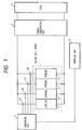
- a solar cell array 1 comprises parallel-connected solar cell strings 11 to 14 each constituted by a plurality of series-connected solar cell modules (which may be simply referred to as modules hereinafter).
- a solar cell module a module using an amorphous silicon (including small crystals), polycrystalline silicon, or crystalline silicon material for a photoelectric conversion unit is preferably used.
- the number of solar cell modules connected in series may be properly set to obtain a necessary voltage used in the solar light generating system. Generally, in Japan, this number is preferably set to obtain 200 V in a system having an output of 3 kW for household applications; and about 300 to 350 V in a large-scale system having an output of 10 kW or more.
- the number of solar cell string connected in parallel must be at least two or more to achieve the object of the present invention. More preferably, several to several hundred parallel circuits are used. That is, in the present invention, the standard value for a defect dynamically changes in accordance with current parameters in solar cell strings or sub-arrays or variation ratios. If, therefore, the number of strings or sub-arrays is small, a proper standard value is difficult to set. This makes it difficult to perform accurate defect detection. For this reason, the number of parallel circuits is preferably three or more, and more preferably, five or more. As the number of strings or sub-arrays increases, an abnormality can be detected more accurately.
- the number of strings or sub-arrays is preferably set to be 100 or less, and more preferably, 30 or less.
- an output from the solar cell array 1 is sent to a power conversion unit 2.
- the power conversion unit 2 converts DC electric power from the solar cells into AC electric power or adjusts the DC voltage or the DC current.
- the power conversion unit 2 may include a control system for maintaining the operating point of each solar cell at the maximum output. Although such a unit is not a constituent element of the present invention, the unit is generally used in a system of a several kW class to effectively use the solar cell output. In addition to or in place of this power conversion unit, the system may be designed to directly use secondary batteries. An output from the power conversion unit 2 is consumed by a load 3.
- the load 3 includes a power-driven device such a motor, a light source such as a lamp, or a heat source such as a laser. More specifically, an air conditioner or the like as an indoor load 31 is exemplified. Alternatively, a storage battery such as a secondary nickel-hydrogen battery, a secondary lithium battery, or a secondary lithium ion battery, a commercial use system 31, or a combination thereof may be used as the load 3.
- a power-driven device such as a motor, a light source such as a lamp, or a heat source such as a laser. More specifically, an air conditioner or the like as an indoor load 31 is exemplified.
- a storage battery such as a secondary nickel-hydrogen battery, a secondary lithium battery, or a secondary lithium ion battery, a commercial use system 31, or a combination thereof may be used as the load 3.
- Electrical parameter detection units 41, 42, 43, and 44 are respectively connected to the solar cell strings 11 to 14.
- the electrical parameters may include a voltage, electric power, or a current.
- a current detection unit is preferably used because the use of a current allows measurements even while the system is in operation.
- a detection unit for detecting an electrical parameter especially a current
- a current sensor using a current measurement standard resistor and a Hall element or the like can be used as detecting a current.
- the detected current value is converted into a voltage, for example, a current of 10 A is converted into a voltage of 100 mV, and the voltage is output and transmitted to a comparing unit 5.
- the voltage value may be transmitted via an optical cable by digital transmission or analog transmission using PWM pulse light.
- the influence of noise can be eliminated, and hence a detection signal can be transmitted to a remote location.
- voltage detection units 91, 92, 93, and 94 are used as electrical parameter detection units, since voltage values can be directly used as parameters, the system arrangement can be simplified.
- detection is preferably performed under a small amount (10 mW/cm2 or less) of light irradiated on each photoelectric conversion unit for detection.
- the comparing unit 5 compares transferred detection values mutually. If there is a defective solar cell string having a relatively low output, i.e., a solar cell string exhibiting a value deviated from a group of normal solar cell strings, the comparing unit 5 determines that the solar cell string group has failed, and transmits an output signal to a warning unit 6.
- the comparing unit 5 is preferably designed to temporarily store the transmitted data and compare the data mutually. With this arrangement, no specific string is used for a standard value. Therefore, the arrangement is especially effective for solar cells each having output characteristics which sequentially change with time. For such an application purpose, a one-chip microcomputer is very suitable. However, the comparing unit 5 may be constituted by using only analog circuits.
- the unit is constituted by only analog circuits, for example, all input values are recorded in a sample/hold circuit, and these values are respectively input to an analog comparator constituted by an operational amplifier so as be compared mutually. Note that comparison values may be switched by an analog switch. In this method, a complicated circuit is required. Therefore, only a first input may be simply used as a standard value. In this case, input values can be sequentially compared mutually, and the circuit can be greatly simplified. Assume that in this method, the first input indicates a failure. Even in this case, if subsequent inputs indicate a normal state, the determination values of the comparing unit shift to the positive side, allowing determination of a non-defective/defective state.
- a mode of comparison with a rated value which can be relatively easily realized, or a mode of using a standard deviation or an exponential distribution, which allows accurate detection of an abnormality, can be used.
- warning unit 6 a liquid crystal display such as a TFT or FLC display, a 7 segment LED, a display used for a personal computer, or the like which is capable of character display can be used. That is, this unit can clearly display a specific place where an abnormality has occurred.
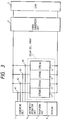
- Fig. 3 shows another abnormality detection apparatus for a solar light power generating system which is suitable for the present invention.
- This apparatus further comprises a recording unit 7 for recording data for a long period of time and allowing the use of the data for maintenance, inspection, and the like, and an arithmetic operation unit 8 for data.
- a recording unit 7 for recording data for a long period of time and allowing the use of the data for maintenance, inspection, and the like
- an arithmetic operation unit 8 for data.
- a magnetic recording medium such as a floppy disk or a semiconductor memory is used.
- a microcomputer As the arithmetic operation unit 8, a microcomputer is suitably used. In practice, for the sake of convenience, the recording unit 7, the arithmetic operation unit 8, and the like may be integrated with the warning unit 6 and the comparing unit 5, as shown in Fig. 3.
- a communication unit 61 either a wired or wireless communication unit may be used to transmit and notify data based on abnormality detection under centralized control.
- a modem is used in a telephone line as a wire.
- Fig. 9 shows only the communication unit 61. However, the communication unit 61 may also serve as a warning unit.
- a control unit 82 is constituted by a one-chip microcomputer and the like.
- the control unit 82 performs disconnection control on the basis of data from the comparing unit 5 to electrically disconnect a power conversion unit connected to a string in which an abnormality is detected from other power conversion units.
- amorphous solar cell module (nominal output: 22 W) available from USSC Corp. was used. Ten solar cell strings having an output voltage of about 200 V were formed. Each string was constituted by 14 amorphous solar cell modules connected in series. Wires were extended from these solar cell strings into a house. These wires were connected in parallel to form a solar cell array having an output of 3 kW. As shown in Fig. 1, the output of this solar cell array was connected to a power conversion unit 2. As the power conversion unit 2, a system interconnection inverter (trade name: Line Back) available from Nihon Denchi K. K. was used. The output of the power conversion unit 2 was connected to a power system serving as a load 3, thereby forming a system interconnection system having the arrangement shown in Fig. 1.
- Ten current sensors (available from U-RD Corp.; trade name: HCS-20-SC-A-2.5) using Hall elements were used in correspondence with the number of solar cell strings so as to detect string currents in the respective solar cell strings. These current sensors serve to measure currents and convert them into voltages without cutting electric wires. Each sensor used in this embodiment converts a current of 1 A into a voltage of 0.2 V. These current detection-elements were arranged on the string wires in the house. Outputs from the elements were input to a personal computer serving both as a comparing unit and a warning unit via an A/D converter. Data was temporarily recorded by the personal computer. The maximum current among solar cell string currents was defined as 100, and output currents from the remaining solar cell strings were compared with this maximum current.
- Fig. 11A shows the initial measurement data of the above measured current values from the respective strings.
- Fig. 11B shows data from the respective strings obtained one year after the above measurement.
- the ordinate axis represents the relative current value; and the abscissa axis, the solar cell string number. Determination is performed with standard to these data.
- solar cell string No. 4 is selected as a standard.
- solar cell string No. 8 is selected as a standard.
- no specific standard string need be used. Solar cell strings exhibiting relatively good relative current values among measurement data are recognized as a group, and a standard string is properly selected from this group. An output from this standard string can be used as a standard value. Alternatively, an average value of outputs from the solar cell strings may be used as a standard value.
- Fig. 11B drops in output have occurred in solar cell strings Nos. 2 and 7. Such a state can be detected, and a warning can be generated. The manager of the system can then take proper measures such as replacement of a solar cell string upon referring to these output drops and the warning.
- a standard value for determining such output drop may be properly determined for each system (solar cell product). More specifically, since many solar cells exhibit output variations of about 10% in the manufacturing process, a drop of, e.g., about 20% may be considered as a standard.
- the present invention is characterized in that the criterion for determining whether solar cell strings are defective dynamically changes in accordance with the installation location of the system. With this characteristic feature, a defective string can be accurately detected regardless of the installation place or the state of deterioration.
- the above embodiment exemplifies the case wherein amorphous solar cell modules are used. However, the same effect as described above can be obtained even if crystalline solar cell modules are used in place of amorphous solar cell modules.
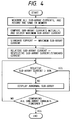
- the operation of Embodiment 1 is shown in the flow chart of Fig. 2.
- a system comprises sub-arrays constituting a solar cell array, in place of solar cell strings in the above embodiment. That is, currents are detected in units of sub-arrays, each including the same number of solar cell modules as that in the above embodiment. A defective sub-array is detected by comparing currents measured from the sub-arrays having the same structure, and an abnormality warning is generated.
- defect detection precision slightly deteriorates because of an increase in the number of modules to be monitored by one sensor, but it is apparent that an effect similar to that of the above embodiment can be obtained. If defect detection is performed in units of sub-arrays in this manner, an abnormality detection apparatus according to the present invention can be easily mounted even in a large-scale solar light power generating system of 100 kW or more.
- Embodiment 3 the arrangement shown in Fig. 3 was realized.
- a solar cell string having a voltage of 180 V was formed by connecting 12 roof-mount type amorphous solar cell modules (nominal output: 22 W) available from USSC Corp. to each other in series.
- a solar cell array was constituted by 58 such solar cell strings connected in parallel.
- a current measurement resistor (0.01 ⁇ ) was used to detect a string current. This detection value was input to a recorder (available from YOKOGAWA ELECTRIC CORP.; trade name: HR2300).
- An output from the recorder was loaded into a personal computer via a GPIB bus, and the data was recorded in a magnetooptical disk.
- a recording unit 7, an arithmetic operation unit 8, a comparing unit 5, and a warning unit 6 were constituted by the personal computer and the magnetooptical disk, and the integral form shown in Fig. 3 was realized.
- Fig. 12 shows relative performance curves representing the relative comparison results obtained by detecting string currents for 180 days.
- a non-defective/defective state of each string is determined, and a defect is detected by using a slope calculation method of calculating the slopes of these relative performance curves at measurement points, i.e., the variation ratios of string currents.
- a non-defective string exhibits a slope of 0 as indicated by "Good”
- a defective string exhibits a negative slope representing a gradual drop in output, as indicated by "Bad”.
- variations in deterioration of solar cell strings are smaller than variations (about ⁇ 10%) in performance of the solar cell modules under the same environment. Therefore, by checking the slope of a relative performance curve based on each string as in the above slope method, a defective string can be detected at a time point at which the corresponding slope becomes negative, i.e., the time point indicated by "F” in Fig. 12, and a warning can be generated.
- the recording unit and the arithmetic operation unit for detected data are arranged to perform arithmetic processing for electrical parameters so as to obtain variation ratios. If a defect is detected by comparing these variation ratios mutually, a warning can be generated more quickly. In addition, since detected data of electrical parameters are recorded, the cause of a failure can be found by using such data.
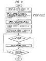
- Embodiment 3 The operation of Embodiment 3 is shown in the flow chart of Fig. 4.
- Fig. 5 shows Embodiment 4.
- a voltage detection unit 9 is used to detect voltages from strings 11 to 14 by using detection units 91 to 94 in place of the current detection unit used as an electrical parameter detection unit in Embodiment 1.
- loads 3 a commercial use system 31 and an indoor load 32 are arranged.
- the arrangement of this embodiment is the same as that of Embodiment 1 except for the above points.
- measurement must be performed after it is confirmed that the light amount is small, i.e., 10 mW/cm2.
- measurement is preferably performed while the circuit is in an open state.
- the present invention can be realized by a relatively simple apparatus arrangement.
- Embodiment 4 is shown in the flow chart of Fig. 6.
- Fig. 7 shows Embodiment 5.
- the arrangement of this embodiment is the same as that of Embodiment 1 except that a solar cell array is divided into two arrays. These two solar cell arrays are arranged at positions where the amounts of incident light are different, and the data of current detection values from the respective arrays are corrected by a correction unit. Thereafter, the data are compared mutually.
- the solar cell arrays can be installed at different angles in the same place at which the amounts of incident light are different.
- Embodiment 5 is shown in the flow chart of Fig. 8.
- Fig. 9 shows Embodiment 6.
- Power conversion is performed by each power conversion unit for each string.
- the resultant values are then detected by electrical parameter detection units 41 to 44, respectively.
- the respective strings are compared mutually by a comparing unit 5.
- a control unit 82 stops a power conversion unit for the corresponding string.
- the corresponding information is displayed on a display at a distant place by a communication unit 61 via a wire.
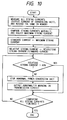
- Embodiment 6 The operation of Embodiment 6 is shown in Fig. 10. As described above, according to the present invention, the following effects can be obtained.
- the present invention is very effective for preventive maintenance of a power generating system, and is especially effective for a large-scale solar light power generating system. Furthermore, such a warning unit is incorporated in a control unit for a power conversion unit so that the system can be operated by using only non-defective portions while a defective portion is disconnected therefrom. Therefore, the reliability of the system can be improved.
Landscapes
- Photovoltaic Devices (AREA)
- Supply And Distribution Of Alternating Current (AREA)
- Charge And Discharge Circuits For Batteries Or The Like (AREA)
- Emergency Alarm Devices (AREA)
Applications Claiming Priority (4)
| Application Number | Priority Date | Filing Date | Title |
|---|---|---|---|
| JP74527/94 | 1994-04-13 | ||
| JP7452794 | 1994-04-13 | ||
| JP86987/95 | 1995-04-12 | ||
| JP7086987A JP2874156B2 (ja) | 1994-04-13 | 1995-04-12 | 発電システム |
Publications (2)
| Publication Number | Publication Date |
|---|---|
| EP0677749A2 true EP0677749A2 (fr) | 1995-10-18 |
| EP0677749A3 EP0677749A3 (fr) | 1996-01-17 |
Family
ID=26415682
Family Applications (1)
| Application Number | Title | Priority Date | Filing Date |
|---|---|---|---|
| EP95302507A Withdrawn EP0677749A3 (fr) | 1994-04-13 | 1995-04-13 | Procédé et dispositif de détection d'anomalie, et système générateur d'énergie électrique l'utilisant. |
Country Status (4)
| Country | Link |
|---|---|
| EP (1) | EP0677749A3 (fr) |
| JP (1) | JP2874156B2 (fr) |
| KR (1) | KR100195686B1 (fr) |
| CN (1) | CN1053502C (fr) |
Cited By (55)
| Publication number | Priority date | Publication date | Assignee | Title |
|---|---|---|---|---|
| US6515215B1 (en) * | 1998-03-13 | 2003-02-04 | Canon Kabushiki Kaisha | Photovoltaic module, photovoltaic module array, photovoltaic system, and method of detecting failure of photovoltaic module |
| US7719140B2 (en) | 2007-10-15 | 2010-05-18 | Ampt, Llc | Systems for boundary controlled solar power conversion |
| EP2293089A1 (fr) | 2009-09-02 | 2011-03-09 | SMA Solar Technology AG | Surveillance de panne de chaîne |
| US7919953B2 (en) | 2007-10-23 | 2011-04-05 | Ampt, Llc | Solar power capacitor alternative switch circuitry system for enhanced capacitor life |
| JP2012182923A (ja) * | 2011-03-02 | 2012-09-20 | Sekisui Chem Co Ltd | 太陽光発電システムおよびその点検方法 |
| WO2012128807A1 (fr) | 2011-03-22 | 2012-09-27 | Sunpower Corporation | Génération et analyse automatiques de courbes de courant et de tension (iv) de cellule solaire |
| EP2541611A1 (fr) * | 2010-02-26 | 2013-01-02 | Kabushiki Kaisha Toshiba | Dispositif et procédé de diagnostic de défaillance |
| EP2317329A3 (fr) * | 2009-10-08 | 2013-04-03 | Adensis GmbH | Poste à courant continu destiné à trouver des modules PV défectueux dans une installation photovoltaïque |
| EP2587274A1 (fr) * | 2011-10-28 | 2013-05-01 | IMS Connector Systems GmbH | Procédé de surveillance des modules photovoltaïques |
| EP2664939A1 (fr) * | 2012-05-18 | 2013-11-20 | Skytron Energy GmbH | Procédé de validation de valeurs de mesure en fonction de la position du soleil sur plusieurs canaux de mesure |
| EP2538450A4 (fr) * | 2010-02-19 | 2015-06-17 | Onamba Co Ltd | Procédé permettant de détecter la défaillance d'un générateur photovoltaïque |
| US9397497B2 (en) | 2013-03-15 | 2016-07-19 | Ampt, Llc | High efficiency interleaved solar power supply system |
| US9442504B2 (en) | 2009-04-17 | 2016-09-13 | Ampt, Llc | Methods and apparatus for adaptive operation of solar power systems |
| US9466737B2 (en) | 2009-10-19 | 2016-10-11 | Ampt, Llc | Solar panel string converter topology |
| US10007288B2 (en) | 2012-03-05 | 2018-06-26 | Solaredge Technologies Ltd. | Direct current link circuit |
| US10097007B2 (en) | 2006-12-06 | 2018-10-09 | Solaredge Technologies Ltd. | Method for distributed power harvesting using DC power sources |
| US10116217B2 (en) | 2007-08-06 | 2018-10-30 | Solaredge Technologies Ltd. | Digital average input current control in power converter |
| US10184965B2 (en) | 2006-12-06 | 2019-01-22 | Solaredge Technologies Ltd. | Monitoring of distributed power harvesting systems using DC power sources |
| EP3416283A4 (fr) * | 2016-03-01 | 2019-02-20 | Huawei Technologies Co., Ltd. | Procédé d'identification de défaut de série de blocs de batteries dans un système photoélectrique, appareil et dispositif |
| US10230245B2 (en) | 2006-12-06 | 2019-03-12 | Solaredge Technologies Ltd | Battery power delivery module |
| US10230310B2 (en) | 2016-04-05 | 2019-03-12 | Solaredge Technologies Ltd | Safety switch for photovoltaic systems |
| US10381977B2 (en) | 2012-01-30 | 2019-08-13 | Solaredge Technologies Ltd | Photovoltaic panel circuitry |
| US10396662B2 (en) | 2011-09-12 | 2019-08-27 | Solaredge Technologies Ltd | Direct current link circuit |
| US10447150B2 (en) | 2006-12-06 | 2019-10-15 | Solaredge Technologies Ltd. | Distributed power harvesting systems using DC power sources |
| US10461687B2 (en) | 2008-12-04 | 2019-10-29 | Solaredge Technologies Ltd. | Testing of a photovoltaic panel |
| US10468878B2 (en) | 2008-05-05 | 2019-11-05 | Solaredge Technologies Ltd. | Direct current power combiner |
| US10608553B2 (en) | 2012-01-30 | 2020-03-31 | Solaredge Technologies Ltd. | Maximizing power in a photovoltaic distributed power system |
| US10637393B2 (en) | 2006-12-06 | 2020-04-28 | Solaredge Technologies Ltd. | Distributed power harvesting systems using DC power sources |
| US10644589B2 (en) | 2007-12-05 | 2020-05-05 | Solaredge Technologies Ltd. | Parallel connected inverters |
| US10666125B2 (en) | 2011-01-12 | 2020-05-26 | Solaredge Technologies Ltd. | Serially connected inverters |
| US10673229B2 (en) | 2010-11-09 | 2020-06-02 | Solaredge Technologies Ltd. | Arc detection and prevention in a power generation system |
| US10673222B2 (en) | 2010-11-09 | 2020-06-02 | Solaredge Technologies Ltd. | Arc detection and prevention in a power generation system |
| US10778025B2 (en) | 2013-03-14 | 2020-09-15 | Solaredge Technologies Ltd. | Method and apparatus for storing and depleting energy |
| US10931119B2 (en) | 2012-01-11 | 2021-02-23 | Solaredge Technologies Ltd. | Photovoltaic module |
| US10931228B2 (en) | 2010-11-09 | 2021-02-23 | Solaredge Technologies Ftd. | Arc detection and prevention in a power generation system |
| US10969412B2 (en) | 2009-05-26 | 2021-04-06 | Solaredge Technologies Ltd. | Theft detection and prevention in a power generation system |
| US10992238B2 (en) | 2012-01-30 | 2021-04-27 | Solaredge Technologies Ltd. | Maximizing power in a photovoltaic distributed power system |
| US11018623B2 (en) | 2016-04-05 | 2021-05-25 | Solaredge Technologies Ltd. | Safety switch for photovoltaic systems |
| US11031861B2 (en) | 2006-12-06 | 2021-06-08 | Solaredge Technologies Ltd. | System and method for protection during inverter shutdown in distributed power installations |
| EP3846338A1 (fr) | 2019-12-31 | 2021-07-07 | MARICI Holdings The Netherlands B.V. | Procédé de détection et d'identification d'un dysfonctionnement d'une installation photovoltaïque |
| US11177663B2 (en) | 2016-04-05 | 2021-11-16 | Solaredge Technologies Ltd. | Chain of power devices |
| US11264947B2 (en) | 2007-12-05 | 2022-03-01 | Solaredge Technologies Ltd. | Testing of a photovoltaic panel |
| US11296650B2 (en) | 2006-12-06 | 2022-04-05 | Solaredge Technologies Ltd. | System and method for protection during inverter shutdown in distributed power installations |
| US11309832B2 (en) | 2006-12-06 | 2022-04-19 | Solaredge Technologies Ltd. | Distributed power harvesting systems using DC power sources |
| US11569660B2 (en) | 2006-12-06 | 2023-01-31 | Solaredge Technologies Ltd. | Distributed power harvesting systems using DC power sources |
| US11569659B2 (en) | 2006-12-06 | 2023-01-31 | Solaredge Technologies Ltd. | Distributed power harvesting systems using DC power sources |
| US11579235B2 (en) | 2006-12-06 | 2023-02-14 | Solaredge Technologies Ltd. | Safety mechanisms, wake up and shutdown methods in distributed power installations |
| US11687112B2 (en) | 2006-12-06 | 2023-06-27 | Solaredge Technologies Ltd. | Distributed power harvesting systems using DC power sources |
| US11728768B2 (en) | 2006-12-06 | 2023-08-15 | Solaredge Technologies Ltd. | Pairing of components in a direct current distributed power generation system |
| US11735910B2 (en) | 2006-12-06 | 2023-08-22 | Solaredge Technologies Ltd. | Distributed power system using direct current power sources |
| US11855231B2 (en) | 2006-12-06 | 2023-12-26 | Solaredge Technologies Ltd. | Distributed power harvesting systems using DC power sources |
| US11881814B2 (en) | 2005-12-05 | 2024-01-23 | Solaredge Technologies Ltd. | Testing of a photovoltaic panel |
| US11888387B2 (en) | 2006-12-06 | 2024-01-30 | Solaredge Technologies Ltd. | Safety mechanisms, wake up and shutdown methods in distributed power installations |
| US12027849B2 (en) | 2006-12-06 | 2024-07-02 | Solaredge Technologies Ltd. | Distributed power system using direct current power sources |
| US12057807B2 (en) | 2016-04-05 | 2024-08-06 | Solaredge Technologies Ltd. | Chain of power devices |
Families Citing this family (63)
| Publication number | Priority date | Publication date | Assignee | Title |
|---|---|---|---|---|
| JP2000068537A (ja) * | 1998-06-12 | 2000-03-03 | Canon Inc | 太陽電池モジュ―ル、ストリングおよびシステムならびに管理方法 |
| JP2000040838A (ja) * | 1998-07-24 | 2000-02-08 | Toshiba Corp | 太陽光発電設備の異常検出装置 |
| JP4123673B2 (ja) * | 2000-03-13 | 2008-07-23 | オムロン株式会社 | 融雪制御装置および太陽光発電システム |
| JP5013637B2 (ja) * | 2000-07-04 | 2012-08-29 | キヤノン株式会社 | 光電変換特性の測定方法およびその装置 |
| JP4552536B2 (ja) * | 2004-07-06 | 2010-09-29 | パナソニック株式会社 | 独立電源装置 |
| JP2007126128A (ja) * | 2005-10-06 | 2007-05-24 | Ntt Facilities Inc | 携帯型日除けシート及びそのシステム |
| CN101311742B (zh) * | 2007-05-22 | 2010-10-06 | 中芯国际集成电路制造(上海)有限公司 | 一种测试太阳电池组件效率的方法 |
| CN101094550B (zh) * | 2007-07-06 | 2010-12-15 | 江苏伯乐达光电科技有限公司 | 带故障自检显示的太阳能路灯控制系统 |
| CN101307756B (zh) * | 2008-07-08 | 2010-06-16 | 河北省电力研究院 | 火力发电机组辅机故障快减负荷给水泵跳闸工况可行性测定方法 |
| JP2010080549A (ja) * | 2008-09-24 | 2010-04-08 | Sekisui Chem Co Ltd | 太陽光発電モジュール |
| US8264195B2 (en) * | 2008-10-01 | 2012-09-11 | Paceco Corp. | Network topology for monitoring and controlling a solar panel array |
| CN101446615B (zh) * | 2008-12-19 | 2012-03-07 | 艾默生网络能源有限公司 | 一种太阳能方阵管理方法 |
| DE102009031839B4 (de) * | 2009-07-03 | 2011-06-09 | Ingmar Kruse | Verfahren zur Überwachung einzelner Photovoltaikmodule in einer Anordnung, die mehrere Photovoltaikmodule umfasst sowie eine Einrichtung zur Durchführung des vorgenannten Verfahrens |
| JP2011119579A (ja) * | 2009-12-07 | 2011-06-16 | Toshiba Corp | 太陽光発電システム |
| WO2011070899A1 (fr) * | 2009-12-07 | 2011-06-16 | 株式会社 東芝 | Système de production d'énergie solaire |
| JP5214650B2 (ja) * | 2010-02-26 | 2013-06-19 | 株式会社東芝 | 異常診断装置および方法 |
| JP5472913B2 (ja) * | 2010-04-23 | 2014-04-16 | 株式会社東芝 | 太陽光発電システムの異常診断装置 |
| KR101283649B1 (ko) * | 2010-03-18 | 2013-07-08 | 현대중공업 주식회사 | 태양광 발전용 접속반의 스트링 오류 검출방법 |
| JP2012044066A (ja) * | 2010-08-20 | 2012-03-01 | Toshiba Corp | 太陽光発電システム |
| KR101061517B1 (ko) | 2010-08-31 | 2011-09-02 | 한국기계연구원 | 덤프로드의 고장을 감지하기 위한 시스템 |
| JP5511622B2 (ja) * | 2010-10-14 | 2014-06-04 | 三菱電機株式会社 | 太陽電池モジュールの故障診断装置および方法 |
| JP5647867B2 (ja) * | 2010-11-10 | 2015-01-07 | 株式会社アイアールエフ | 太陽光発電パネルの診断装置、遮音壁、建造物用窓ガラス設備、乗物用窓ガラス設備及び太陽光発電パネルの保守管理システム |
| JP5649938B2 (ja) * | 2010-12-07 | 2015-01-07 | 株式会社アイアールエフ | 太陽光発電パネル、及び太陽光発電パネルを備える遮音壁、建造物用窓パネル設備、乗物用窓パネル設備、並びに太陽光発電パネルの診断装置、太陽光発電パネルの保守管理システム |
| US9300153B2 (en) * | 2011-05-12 | 2016-03-29 | Sharp Kabushiki Kaisha | Charging control unit |
| JP5879079B2 (ja) * | 2011-09-16 | 2016-03-08 | 東芝三菱電機産業システム株式会社 | 太陽光発電装置 |
| JP5744214B2 (ja) * | 2011-09-20 | 2015-07-08 | 三菱電機株式会社 | 太陽光発電システム、太陽光発電システムの診断装置、太陽光発電システムの診断方法、及びプログラム |
| US8933721B2 (en) * | 2011-10-27 | 2015-01-13 | Infineon Technologies Austria Ag | Power source arrangement and method of diagnosing a power source arrangement |
| CN102569430A (zh) * | 2012-01-12 | 2012-07-11 | 苏州清莲纳米环保科技有限公司 | 太阳能电池组 |
| JP6029285B2 (ja) * | 2012-02-16 | 2016-11-24 | 株式会社ニケ・ウィング | 太陽電池モジュールの異常検出装置、異常検出設備、並びに太陽光発電装置 |
| JP6023458B2 (ja) * | 2012-04-24 | 2016-11-09 | 上新電機株式会社 | 太陽電池システム |
| CN102705944B (zh) * | 2012-06-28 | 2014-11-19 | 南车株洲电力机车研究所有限公司 | 一种太阳能变频空调系统 |
| EP2880454B1 (fr) * | 2012-08-03 | 2021-06-30 | SMA Solar Technology AG | Détection de courant de fuite et de defaut et détection d'un défaut d'un string |
| JP2014087133A (ja) * | 2012-10-22 | 2014-05-12 | Sharp Corp | 太陽光発電システム、パワーコンディショナ、系統抜け検出装置、および太陽光発電システムにおける系統抜けの検出方法 |
| JP2014093368A (ja) * | 2012-11-01 | 2014-05-19 | Toyota Industries Corp | 太陽光発電パネル異常検知装置 |
| JP5939683B2 (ja) * | 2012-12-05 | 2016-06-22 | 太平洋工業株式会社 | クラスタ状態監視装置 |
| KR101270534B1 (ko) | 2012-12-27 | 2013-06-03 | 한양전공주식회사 | 태양광 전지 어레이의 모니터링 방법 및 장치 |
| JP5273690B1 (ja) * | 2013-02-05 | 2013-08-28 | 株式会社ヒロセー | 太陽光発電システム |
| JP6087200B2 (ja) * | 2013-04-25 | 2017-03-01 | 京セラ株式会社 | 太陽光発電システムの異常検出装置、異常検出方法、及び太陽光発電システム |
| JP6012130B2 (ja) * | 2013-05-09 | 2016-10-25 | 太平洋工業株式会社 | クラスタ状態監視装置 |
| JP5634561B1 (ja) * | 2013-05-20 | 2014-12-03 | アクソンデータマシン株式会社 | 太陽光発電システム用のモニタ装置 |
| JP6226593B2 (ja) * | 2013-07-09 | 2017-11-08 | 三菱電機ビルテクノサービス株式会社 | 太陽光発電システム |
| WO2015022728A1 (fr) * | 2013-08-13 | 2015-02-19 | 株式会社日立システムズ | Système d'inspection de production d'électricité solaire et procédé d'inspection de production d'électricité solaire |
| JP6436329B2 (ja) * | 2013-11-05 | 2018-12-12 | パナソニックIpマネジメント株式会社 | 分散型電源の状態検知プログラム、記録媒体、監視端末及び通信装置 |
| JP6256977B2 (ja) * | 2014-01-06 | 2018-01-10 | 株式会社ニケ・ウィング | 太陽光発電装置 |
| JP6277437B2 (ja) * | 2014-02-25 | 2018-02-14 | 日東工業株式会社 | 太陽光発電システム |
| JP5567752B1 (ja) * | 2014-02-25 | 2014-08-06 | 株式会社ヒロセー | ストリング監視システム |
| JP2015192519A (ja) * | 2014-03-28 | 2015-11-02 | 太平洋工業株式会社 | モジュール端末及びクラスタ状態監視装置 |
| JP6507382B2 (ja) * | 2014-07-22 | 2019-05-08 | 日東工業株式会社 | 太陽光発電システム |
| WO2016085010A1 (fr) * | 2014-11-28 | 2016-06-02 | (주)대은 | Système et procédé pour diagnostiquer efficacement si une anomalie existe dans chaque module solaire |
| JP6501535B2 (ja) * | 2015-01-30 | 2019-04-17 | 東京電力ホールディングス株式会社 | 太陽光発電システムの発電状況診断方法及びその装置 |
| JP6005775B2 (ja) * | 2015-02-12 | 2016-10-12 | 株式会社ニプロン | 太陽光発電システム |
| KR101618299B1 (ko) * | 2015-12-30 | 2016-05-04 | 운지파워텍(주) | 태양광발전시스템의 모니터링 방법 및 장치 |
| JP6756188B2 (ja) * | 2016-08-08 | 2020-09-16 | 住友電気工業株式会社 | 発電状態判定装置、発電状態判定方法および判定プログラム |
| KR101870346B1 (ko) * | 2016-09-30 | 2018-06-22 | 헵시바주식회사 | 멀티스트링 태양광 인버터에 연결된 멀티스트링 태양전지 고장 진단 방법 |
| US10180452B2 (en) * | 2016-12-16 | 2019-01-15 | Nortek Security & Control Llc | Doorbell camera test tool |
| CN108572319B (zh) * | 2017-03-09 | 2024-06-21 | 深圳市三诺声智联股份有限公司 | 并联电池组检测装置及方法 |
| CN107449991A (zh) * | 2017-07-17 | 2017-12-08 | 珠海格力电器股份有限公司 | 电加热模块异常运行检测方法和装置及空调器 |
| KR102144350B1 (ko) | 2017-12-05 | 2020-08-13 | 유성희 | 태양광 발전시스템의 고장 진단 시스템 |
| CN108964608A (zh) * | 2018-06-30 | 2018-12-07 | 苏州格远电气有限公司 | 组串式光伏阵列单板电压采集系统和方法 |
| CN108964606B (zh) * | 2018-08-23 | 2019-12-20 | 上海电气分布式能源科技有限公司 | 一种光伏系统热斑故障检测方法 |
| JP6664027B1 (ja) * | 2019-08-20 | 2020-03-13 | 株式会社ミライト | 太陽電池ストリングの劣化検出方法、劣化検出システム及び劣化検出装置 |
| JP6698234B1 (ja) * | 2020-02-17 | 2020-05-27 | 株式会社ミライト | 太陽電池ストリングの劣化検出方法、劣化検出システム及び劣化検出装置 |
| CN111443253B (zh) * | 2020-04-17 | 2021-07-23 | 福州大学 | 一种基于转换效率的电力电子设备软故障诊断方法及系统 |
Citations (2)
| Publication number | Priority date | Publication date | Assignee | Title |
|---|---|---|---|---|
| DE8815963U1 (de) * | 1988-12-23 | 1989-03-16 | Licentia Patent-Verwaltungs-Gmbh, 6000 Frankfurt | Solargenerator |
| DE4032569A1 (de) * | 1990-10-13 | 1992-04-16 | Flachglas Solartechnik Gmbh | Netzgekoppelte photovoltaikanlage |
-
1995
- 1995-04-12 JP JP7086987A patent/JP2874156B2/ja not_active Expired - Fee Related
- 1995-04-13 CN CN95105107A patent/CN1053502C/zh not_active Expired - Fee Related
- 1995-04-13 EP EP95302507A patent/EP0677749A3/fr not_active Withdrawn
- 1995-04-13 KR KR1019950008609A patent/KR100195686B1/ko not_active IP Right Cessation
Patent Citations (2)
| Publication number | Priority date | Publication date | Assignee | Title |
|---|---|---|---|---|
| DE8815963U1 (de) * | 1988-12-23 | 1989-03-16 | Licentia Patent-Verwaltungs-Gmbh, 6000 Frankfurt | Solargenerator |
| DE4032569A1 (de) * | 1990-10-13 | 1992-04-16 | Flachglas Solartechnik Gmbh | Netzgekoppelte photovoltaikanlage |
Non-Patent Citations (2)
| Title |
|---|
| COMMISSION OF EUROPEAN COMMUNITIES. NINTH E.C.PHOTOVOLTAIC SOLAR ENERGY CONFERENCE. PROCEEDINGS OF THE INTERNATIONAL CONFERENCE, 25 - 29 September 1989 FREIBURG, WEST GERMANY, pages 209-211, SPIRITO ET AL. 'EXPERIMENTAL DETECTION OF MODULE FAILURE IN LARGE PHOTOVOLTAIC ARRAYS...' * |
| NTIS TECH NOTES, no. 9-B, September 1984 SPRINGFIELD, VA US, page 678 MALONEY 'DETECTING SOLAR-CELL FAILURES' * |
Cited By (140)
| Publication number | Priority date | Publication date | Assignee | Title |
|---|---|---|---|---|
| US6515215B1 (en) * | 1998-03-13 | 2003-02-04 | Canon Kabushiki Kaisha | Photovoltaic module, photovoltaic module array, photovoltaic system, and method of detecting failure of photovoltaic module |
| US6979771B2 (en) | 1998-03-13 | 2005-12-27 | Canon Kabushiki Kaisha | Photovoltaic module, photovoltaic module array, photovoltaic system, and method of detecting failure of photovoltaic module |
| US11881814B2 (en) | 2005-12-05 | 2024-01-23 | Solaredge Technologies Ltd. | Testing of a photovoltaic panel |
| US11594881B2 (en) | 2006-12-06 | 2023-02-28 | Solaredge Technologies Ltd. | Distributed power harvesting systems using DC power sources |
| US11594882B2 (en) | 2006-12-06 | 2023-02-28 | Solaredge Technologies Ltd. | Distributed power harvesting systems using DC power sources |
| US12068599B2 (en) | 2006-12-06 | 2024-08-20 | Solaredge Technologies Ltd. | System and method for protection during inverter shutdown in distributed power installations |
| US12046940B2 (en) | 2006-12-06 | 2024-07-23 | Solaredge Technologies Ltd. | Battery power control |
| US12032080B2 (en) | 2006-12-06 | 2024-07-09 | Solaredge Technologies Ltd. | Safety mechanisms, wake up and shutdown methods in distributed power installations |
| US10637393B2 (en) | 2006-12-06 | 2020-04-28 | Solaredge Technologies Ltd. | Distributed power harvesting systems using DC power sources |
| US11031861B2 (en) | 2006-12-06 | 2021-06-08 | Solaredge Technologies Ltd. | System and method for protection during inverter shutdown in distributed power installations |
| US12027970B2 (en) | 2006-12-06 | 2024-07-02 | Solaredge Technologies Ltd. | Safety mechanisms, wake up and shutdown methods in distributed power installations |
| US12027849B2 (en) | 2006-12-06 | 2024-07-02 | Solaredge Technologies Ltd. | Distributed power system using direct current power sources |
| US11043820B2 (en) | 2006-12-06 | 2021-06-22 | Solaredge Technologies Ltd. | Battery power delivery module |
| US11961922B2 (en) | 2006-12-06 | 2024-04-16 | Solaredge Technologies Ltd. | Distributed power harvesting systems using DC power sources |
| US11962243B2 (en) | 2006-12-06 | 2024-04-16 | Solaredge Technologies Ltd. | Method for distributed power harvesting using DC power sources |
| US11888387B2 (en) | 2006-12-06 | 2024-01-30 | Solaredge Technologies Ltd. | Safety mechanisms, wake up and shutdown methods in distributed power installations |
| US11855231B2 (en) | 2006-12-06 | 2023-12-26 | Solaredge Technologies Ltd. | Distributed power harvesting systems using DC power sources |
| US11735910B2 (en) | 2006-12-06 | 2023-08-22 | Solaredge Technologies Ltd. | Distributed power system using direct current power sources |
| US11728768B2 (en) | 2006-12-06 | 2023-08-15 | Solaredge Technologies Ltd. | Pairing of components in a direct current distributed power generation system |
| US11687112B2 (en) | 2006-12-06 | 2023-06-27 | Solaredge Technologies Ltd. | Distributed power harvesting systems using DC power sources |
| US11682918B2 (en) | 2006-12-06 | 2023-06-20 | Solaredge Technologies Ltd. | Battery power delivery module |
| US11658482B2 (en) | 2006-12-06 | 2023-05-23 | Solaredge Technologies Ltd. | Distributed power harvesting systems using DC power sources |
| US11598652B2 (en) | 2006-12-06 | 2023-03-07 | Solaredge Technologies Ltd. | Monitoring of distributed power harvesting systems using DC power sources |
| US11594880B2 (en) | 2006-12-06 | 2023-02-28 | Solaredge Technologies Ltd. | Distributed power harvesting systems using DC power sources |
| US10447150B2 (en) | 2006-12-06 | 2019-10-15 | Solaredge Technologies Ltd. | Distributed power harvesting systems using DC power sources |
| US10673253B2 (en) | 2006-12-06 | 2020-06-02 | Solaredge Technologies Ltd. | Battery power delivery module |
| US11579235B2 (en) | 2006-12-06 | 2023-02-14 | Solaredge Technologies Ltd. | Safety mechanisms, wake up and shutdown methods in distributed power installations |
| US11575260B2 (en) | 2006-12-06 | 2023-02-07 | Solaredge Technologies Ltd. | Distributed power harvesting systems using DC power sources |
| US11575261B2 (en) | 2006-12-06 | 2023-02-07 | Solaredge Technologies Ltd. | Distributed power harvesting systems using DC power sources |
| US11569659B2 (en) | 2006-12-06 | 2023-01-31 | Solaredge Technologies Ltd. | Distributed power harvesting systems using DC power sources |
| US11569660B2 (en) | 2006-12-06 | 2023-01-31 | Solaredge Technologies Ltd. | Distributed power harvesting systems using DC power sources |
| US11476799B2 (en) | 2006-12-06 | 2022-10-18 | Solaredge Technologies Ltd. | Distributed power harvesting systems using DC power sources |
| US11309832B2 (en) | 2006-12-06 | 2022-04-19 | Solaredge Technologies Ltd. | Distributed power harvesting systems using DC power sources |
| US11296650B2 (en) | 2006-12-06 | 2022-04-05 | Solaredge Technologies Ltd. | System and method for protection during inverter shutdown in distributed power installations |
| US11183922B2 (en) | 2006-12-06 | 2021-11-23 | Solaredge Technologies Ltd. | Distributed power harvesting systems using DC power sources |
| US10097007B2 (en) | 2006-12-06 | 2018-10-09 | Solaredge Technologies Ltd. | Method for distributed power harvesting using DC power sources |
| US11073543B2 (en) | 2006-12-06 | 2021-07-27 | Solaredge Technologies Ltd. | Monitoring of distributed power harvesting systems using DC power sources |
| US11002774B2 (en) | 2006-12-06 | 2021-05-11 | Solaredge Technologies Ltd. | Monitoring of distributed power harvesting systems using DC power sources |
| US10184965B2 (en) | 2006-12-06 | 2019-01-22 | Solaredge Technologies Ltd. | Monitoring of distributed power harvesting systems using DC power sources |
| US11063440B2 (en) | 2006-12-06 | 2021-07-13 | Solaredge Technologies Ltd. | Method for distributed power harvesting using DC power sources |
| US10230245B2 (en) | 2006-12-06 | 2019-03-12 | Solaredge Technologies Ltd | Battery power delivery module |
| US8093756B2 (en) | 2007-02-15 | 2012-01-10 | Ampt, Llc | AC power systems for renewable electrical energy |
| US10116217B2 (en) | 2007-08-06 | 2018-10-30 | Solaredge Technologies Ltd. | Digital average input current control in power converter |
| US11594968B2 (en) | 2007-08-06 | 2023-02-28 | Solaredge Technologies Ltd. | Digital average input current control in power converter |
| US10516336B2 (en) | 2007-08-06 | 2019-12-24 | Solaredge Technologies Ltd. | Digital average input current control in power converter |
| US7843085B2 (en) | 2007-10-15 | 2010-11-30 | Ampt, Llc | Systems for highly efficient solar power |
| US11070063B2 (en) | 2007-10-15 | 2021-07-20 | Ampt, Llc | Method for alternating conversion solar power |
| US11228182B2 (en) | 2007-10-15 | 2022-01-18 | Ampt, Llc | Converter disabling photovoltaic electrical energy power system |
| US11289917B1 (en) | 2007-10-15 | 2022-03-29 | Ampt, Llc | Optimized photovoltaic conversion system |
| US9673630B2 (en) | 2007-10-15 | 2017-06-06 | Ampt, Llc | Protected conversion solar power system |
| US9438037B2 (en) | 2007-10-15 | 2016-09-06 | Ampt, Llc | Systems for optimized solar power inversion |
| US10608437B2 (en) | 2007-10-15 | 2020-03-31 | Ampt, Llc | Feedback based photovoltaic conversion systems |
| US11070062B2 (en) | 2007-10-15 | 2021-07-20 | Ampt, Llc | Photovoltaic conversion systems |
| US8482153B2 (en) | 2007-10-15 | 2013-07-09 | Ampt, Llc | Systems for optimized solar power inversion |
| US7719140B2 (en) | 2007-10-15 | 2010-05-18 | Ampt, Llc | Systems for boundary controlled solar power conversion |
| US8004116B2 (en) | 2007-10-15 | 2011-08-23 | Ampt, Llc | Highly efficient solar power systems |
| US8242634B2 (en) | 2007-10-15 | 2012-08-14 | Ampt, Llc | High efficiency remotely controllable solar energy system |
| US10326283B2 (en) | 2007-10-15 | 2019-06-18 | Ampt, Llc | Converter intuitive photovoltaic electrical energy power system |
| US8304932B2 (en) | 2007-10-15 | 2012-11-06 | Ampt, Llc | Efficient solar energy power creation systems |
| US12027869B2 (en) | 2007-10-15 | 2024-07-02 | Ampt, Llc | Optimized photovoltaic conversion configuration |
| US12027867B2 (en) | 2007-10-15 | 2024-07-02 | Ampt, Llc | Coordinated converter reactively altering disabling photovoltaic electrical energy power system |
| US10886746B1 (en) | 2007-10-15 | 2021-01-05 | Ampt, Llc | Alternating conversion solar power system |
| US12003110B2 (en) | 2007-10-15 | 2024-06-04 | Ampt, Llc | Optimized conversion system |
| US8461811B2 (en) | 2007-10-23 | 2013-06-11 | Ampt, Llc | Power capacitor alternative switch circuitry system for enhanced capacitor life |
| US7919953B2 (en) | 2007-10-23 | 2011-04-05 | Ampt, Llc | Solar power capacitor alternative switch circuitry system for enhanced capacitor life |
| US11894806B2 (en) | 2007-12-05 | 2024-02-06 | Solaredge Technologies Ltd. | Testing of a photovoltaic panel |
| US11183923B2 (en) | 2007-12-05 | 2021-11-23 | Solaredge Technologies Ltd. | Parallel connected inverters |
| US11183969B2 (en) | 2007-12-05 | 2021-11-23 | Solaredge Technologies Ltd. | Testing of a photovoltaic panel |
| US12055647B2 (en) | 2007-12-05 | 2024-08-06 | Solaredge Technologies Ltd. | Parallel connected inverters |
| US11264947B2 (en) | 2007-12-05 | 2022-03-01 | Solaredge Technologies Ltd. | Testing of a photovoltaic panel |
| US10644589B2 (en) | 2007-12-05 | 2020-05-05 | Solaredge Technologies Ltd. | Parallel connected inverters |
| US11693080B2 (en) | 2007-12-05 | 2023-07-04 | Solaredge Technologies Ltd. | Parallel connected inverters |
| US10693415B2 (en) | 2007-12-05 | 2020-06-23 | Solaredge Technologies Ltd. | Testing of a photovoltaic panel |
| US10468878B2 (en) | 2008-05-05 | 2019-11-05 | Solaredge Technologies Ltd. | Direct current power combiner |
| US11424616B2 (en) | 2008-05-05 | 2022-08-23 | Solaredge Technologies Ltd. | Direct current power combiner |
| US10461687B2 (en) | 2008-12-04 | 2019-10-29 | Solaredge Technologies Ltd. | Testing of a photovoltaic panel |
| US10326282B2 (en) | 2009-04-17 | 2019-06-18 | Ampt, Llc | Safety methods and apparatus for adaptive operation of solar power systems |
| US9442504B2 (en) | 2009-04-17 | 2016-09-13 | Ampt, Llc | Methods and apparatus for adaptive operation of solar power systems |
| US10938219B2 (en) | 2009-04-17 | 2021-03-02 | Ampt, Llc | Dynamic methods and apparatus for adaptive operation of solar power systems |
| US11867729B2 (en) | 2009-05-26 | 2024-01-09 | Solaredge Technologies Ltd. | Theft detection and prevention in a power generation system |
| US10969412B2 (en) | 2009-05-26 | 2021-04-06 | Solaredge Technologies Ltd. | Theft detection and prevention in a power generation system |
| WO2011026874A3 (fr) * | 2009-09-02 | 2013-04-25 | Sma Solar Technology Ag | Surveillance de panne de chaîne |
| DE112010003528T5 (de) | 2009-09-02 | 2012-10-18 | Sma Solar Technology Ag | Stringausfallüberwachung |
| EP2293089A1 (fr) | 2009-09-02 | 2011-03-09 | SMA Solar Technology AG | Surveillance de panne de chaîne |
| DE112010003528B4 (de) * | 2009-09-02 | 2021-04-29 | Sma Solar Technology Ag | Stringausfallüberwachung |
| CN102947718A (zh) * | 2009-09-02 | 2013-02-27 | 艾思玛太阳能技术股份公司 | 串故障监控 |
| WO2011026874A2 (fr) | 2009-09-02 | 2011-03-10 | Sma Solar Technology Ag | Surveillance de panne de chaîne |
| EP2317329A3 (fr) * | 2009-10-08 | 2013-04-03 | Adensis GmbH | Poste à courant continu destiné à trouver des modules PV défectueux dans une installation photovoltaïque |
| US11411126B2 (en) | 2009-10-19 | 2022-08-09 | Ampt, Llc | DC power conversion circuit |
| US10714637B2 (en) | 2009-10-19 | 2020-07-14 | Ampt, Llc | DC power conversion circuit |
| US12034087B2 (en) | 2009-10-19 | 2024-07-09 | Ampt, Llc | Solar panel power conversion circuit |
| US10032939B2 (en) | 2009-10-19 | 2018-07-24 | Ampt, Llc | DC power conversion circuit |
| US9466737B2 (en) | 2009-10-19 | 2016-10-11 | Ampt, Llc | Solar panel string converter topology |
| EP2538450A4 (fr) * | 2010-02-19 | 2015-06-17 | Onamba Co Ltd | Procédé permettant de détecter la défaillance d'un générateur photovoltaïque |
| US9209743B2 (en) | 2010-02-26 | 2015-12-08 | Kabushiki Kaisha Toshiba | Fault detection apparatus and fault detection method |
| EP2541611A4 (fr) * | 2010-02-26 | 2013-11-06 | Toshiba Kk | Dispositif et procédé de diagnostic de défaillance |
| EP2541611A1 (fr) * | 2010-02-26 | 2013-01-02 | Kabushiki Kaisha Toshiba | Dispositif et procédé de diagnostic de défaillance |
| US10673222B2 (en) | 2010-11-09 | 2020-06-02 | Solaredge Technologies Ltd. | Arc detection and prevention in a power generation system |
| US11489330B2 (en) | 2010-11-09 | 2022-11-01 | Solaredge Technologies Ltd. | Arc detection and prevention in a power generation system |
| US11349432B2 (en) | 2010-11-09 | 2022-05-31 | Solaredge Technologies Ltd. | Arc detection and prevention in a power generation system |
| US11070051B2 (en) | 2010-11-09 | 2021-07-20 | Solaredge Technologies Ltd. | Arc detection and prevention in a power generation system |
| US10673229B2 (en) | 2010-11-09 | 2020-06-02 | Solaredge Technologies Ltd. | Arc detection and prevention in a power generation system |
| US10931228B2 (en) | 2010-11-09 | 2021-02-23 | Solaredge Technologies Ftd. | Arc detection and prevention in a power generation system |
| US12003215B2 (en) | 2010-11-09 | 2024-06-04 | Solaredge Technologies Ltd. | Arc detection and prevention in a power generation system |
| US11205946B2 (en) | 2011-01-12 | 2021-12-21 | Solaredge Technologies Ltd. | Serially connected inverters |
| US10666125B2 (en) | 2011-01-12 | 2020-05-26 | Solaredge Technologies Ltd. | Serially connected inverters |
| JP2012182923A (ja) * | 2011-03-02 | 2012-09-20 | Sekisui Chem Co Ltd | 太陽光発電システムおよびその点検方法 |
| EP2689308A1 (fr) * | 2011-03-22 | 2014-01-29 | SunPower Corporation | Génération et analyse automatiques de courbes de courant et de tension (iv) de cellule solaire |
| EP2689308A4 (fr) * | 2011-03-22 | 2015-11-25 | Sunpower Corp | Génération et analyse automatiques de courbes de courant et de tension (iv) de cellule solaire |
| WO2012128807A1 (fr) | 2011-03-22 | 2012-09-27 | Sunpower Corporation | Génération et analyse automatiques de courbes de courant et de tension (iv) de cellule solaire |
| US10396662B2 (en) | 2011-09-12 | 2019-08-27 | Solaredge Technologies Ltd | Direct current link circuit |
| EP2587274A1 (fr) * | 2011-10-28 | 2013-05-01 | IMS Connector Systems GmbH | Procédé de surveillance des modules photovoltaïques |
| US11979037B2 (en) | 2012-01-11 | 2024-05-07 | Solaredge Technologies Ltd. | Photovoltaic module |
| US10931119B2 (en) | 2012-01-11 | 2021-02-23 | Solaredge Technologies Ltd. | Photovoltaic module |
| US11929620B2 (en) | 2012-01-30 | 2024-03-12 | Solaredge Technologies Ltd. | Maximizing power in a photovoltaic distributed power system |
| US11183968B2 (en) | 2012-01-30 | 2021-11-23 | Solaredge Technologies Ltd. | Photovoltaic panel circuitry |
| US10992238B2 (en) | 2012-01-30 | 2021-04-27 | Solaredge Technologies Ltd. | Maximizing power in a photovoltaic distributed power system |
| US11620885B2 (en) | 2012-01-30 | 2023-04-04 | Solaredge Technologies Ltd. | Photovoltaic panel circuitry |
| US10608553B2 (en) | 2012-01-30 | 2020-03-31 | Solaredge Technologies Ltd. | Maximizing power in a photovoltaic distributed power system |
| US10381977B2 (en) | 2012-01-30 | 2019-08-13 | Solaredge Technologies Ltd | Photovoltaic panel circuitry |
| US12094306B2 (en) | 2012-01-30 | 2024-09-17 | Solaredge Technologies Ltd. | Photovoltaic panel circuitry |
| US10007288B2 (en) | 2012-03-05 | 2018-06-26 | Solaredge Technologies Ltd. | Direct current link circuit |
| US9644958B2 (en) | 2012-03-18 | 2017-05-09 | Skytron Energy Gmbh | Method for the validation of solar altitude-dependent measured values of several measurement channels |
| EP2664939A1 (fr) * | 2012-05-18 | 2013-11-20 | Skytron Energy GmbH | Procédé de validation de valeurs de mesure en fonction de la position du soleil sur plusieurs canaux de mesure |
| US12003107B2 (en) | 2013-03-14 | 2024-06-04 | Solaredge Technologies Ltd. | Method and apparatus for storing and depleting energy |
| US10778025B2 (en) | 2013-03-14 | 2020-09-15 | Solaredge Technologies Ltd. | Method and apparatus for storing and depleting energy |
| US11967653B2 (en) | 2013-03-15 | 2024-04-23 | Ampt, Llc | Phased solar power supply system |
| US11121556B2 (en) | 2013-03-15 | 2021-09-14 | Ampt, Llc | Magnetically coupled solar power supply system for battery based loads |
| US9397497B2 (en) | 2013-03-15 | 2016-07-19 | Ampt, Llc | High efficiency interleaved solar power supply system |
| US10116140B2 (en) | 2013-03-15 | 2018-10-30 | Ampt, Llc | Magnetically coupled solar power supply system |
| US12057514B2 (en) | 2013-03-15 | 2024-08-06 | Ampt, Llc | Converter controlled solar power supply system for battery based loads |
| US10985696B2 (en) | 2016-03-01 | 2021-04-20 | Huawei Technologies Co., Ltd. | Method, apparatus, and device for identifying cell string fault in optoelectronic system |
| EP3416283A4 (fr) * | 2016-03-01 | 2019-02-20 | Huawei Technologies Co., Ltd. | Procédé d'identification de défaut de série de blocs de batteries dans un système photoélectrique, appareil et dispositif |
| US11177663B2 (en) | 2016-04-05 | 2021-11-16 | Solaredge Technologies Ltd. | Chain of power devices |
| US11201476B2 (en) | 2016-04-05 | 2021-12-14 | Solaredge Technologies Ltd. | Photovoltaic power device and wiring |
| US10230310B2 (en) | 2016-04-05 | 2019-03-12 | Solaredge Technologies Ltd | Safety switch for photovoltaic systems |
| US12057807B2 (en) | 2016-04-05 | 2024-08-06 | Solaredge Technologies Ltd. | Chain of power devices |
| US11018623B2 (en) | 2016-04-05 | 2021-05-25 | Solaredge Technologies Ltd. | Safety switch for photovoltaic systems |
| US11870250B2 (en) | 2016-04-05 | 2024-01-09 | Solaredge Technologies Ltd. | Chain of power devices |
| EP3846338A1 (fr) | 2019-12-31 | 2021-07-07 | MARICI Holdings The Netherlands B.V. | Procédé de détection et d'identification d'un dysfonctionnement d'une installation photovoltaïque |
Also Published As
| Publication number | Publication date |
|---|---|
| KR100195686B1 (ko) | 1999-06-15 |
| CN1124847A (zh) | 1996-06-19 |
| JP2874156B2 (ja) | 1999-03-24 |
| JPH07334767A (ja) | 1995-12-22 |
| KR950030402A (ko) | 1995-11-24 |
| EP0677749A3 (fr) | 1996-01-17 |
| CN1053502C (zh) | 2000-06-14 |
Similar Documents
| Publication | Publication Date | Title |
|---|---|---|
| US5669987A (en) | Abnormality detection method, abnormality detection apparatus, and solar cell power generating system using the same | |
| EP0677749A2 (fr) | Procédé et dispositif de détection d'anomalie, et système générateur d'énergie électrique l'utilisant | |
| US8446043B1 (en) | Photovoltaic array systems, methods, and devices and improved diagnostics and monitoring | |
| JP3165606B2 (ja) | 太陽電池モジュールの異常チェック機能付連系形太陽光発電装置 | |
| JP5162737B2 (ja) | 太陽電池の特性評価装置 | |
| US9304161B2 (en) | Solar power generation system, abnormality detection method, and abnormality detection system | |
| EP2426725B1 (fr) | Appareil pour détecter une anomalie d'un système de génération d'énergie à cellules photovoltaïques, et procédé associé | |
| KR101939156B1 (ko) | 다채널 태양광 dc 어레이 고장진단 장치 | |
| KR101535056B1 (ko) | 계통연계형 태양광발전 시스템의 고장 검출 진단 장치 및 그 방법 | |
| JPH07177652A (ja) | 太陽光発電システムおよび太陽光発電システムの保護方式 | |
| KR102182820B1 (ko) | 태양광 모듈의 고장 및 열화 상태 진단 기능을 갖는 태양광 발전장치 및 그 발전 관리방법 | |
| US10992257B2 (en) | State of health mechanisms for energy generation systems | |
| JP3258862B2 (ja) | 太陽電池出力点検機能を有する連系インバータ | |
| JPH0864653A (ja) | 太陽電池診断システム | |
| JP2000040838A (ja) | 太陽光発電設備の異常検出装置 | |
| JP2014232770A (ja) | 太陽光発電システム装置 | |
| KR20220036022A (ko) | 태양광발전시스템 스트링 고장상태 진단 방법 및 시스템 | |
| KR20120094334A (ko) | 계통연계형 태양광발전 시스템의 발전성능 추정 방법 및 그 장치 | |
| KR101402587B1 (ko) | 진단 부하를 이용하는 태양전지 스트링 고장 진단 장치 | |
| JP2019216547A (ja) | 電力制御装置、太陽光発電システム、太陽光発電設備の不具合診断方法 | |
| JP2000207662A (ja) | 太陽電池の発電量異常検出装置および方法並びに同装置を備えた集電箱および太陽光発電システム | |
| JP2011187808A (ja) | 太陽光発電システム | |
| Hemananth et al. | Photovoltaic System Fault Detection Using Voltage/Current Tracking | |
| Mulyodinoto et al. | Leveraging Performance Evaluation through Special Maintenance of Photo Voltaic Power Plant in Nusa Tenggara Region to Achieve Photovoltaic Reliability Excellence |
Legal Events
| Date | Code | Title | Description |
|---|---|---|---|
| PUAI | Public reference made under article 153(3) epc to a published international application that has entered the european phase |
Free format text: ORIGINAL CODE: 0009012 |
|
| AK | Designated contracting states |
Kind code of ref document: A2 Designated state(s): CH DE ES FR GB IT LI |
|
| PUAL | Search report despatched |
Free format text: ORIGINAL CODE: 0009013 |
|
| AK | Designated contracting states |
Kind code of ref document: A3 Designated state(s): CH DE ES FR GB IT LI |
|
| 17P | Request for examination filed |
Effective date: 19960530 |
|
| 17Q | First examination report despatched |
Effective date: 19990115 |
|
| GRAP | Despatch of communication of intention to grant a patent |
Free format text: ORIGINAL CODE: EPIDOSNIGR1 |
|
| RTI1 | Title (correction) |
Free format text: POWER GENERATOR AND ABNORMALITY DETECTION METHOD FOR A POWER GENERATING SYSTEM |
|
| STAA | Information on the status of an ep patent application or granted ep patent |
Free format text: STATUS: THE APPLICATION HAS BEEN WITHDRAWN |
|
| 18W | Application withdrawn |
Effective date: 20060710 |