EP2880454B1 - Détection de courant de fuite et de defaut et détection d'un défaut d'un string - Google Patents
Détection de courant de fuite et de defaut et détection d'un défaut d'un string Download PDFInfo
- Publication number
- EP2880454B1 EP2880454B1 EP13742186.3A EP13742186A EP2880454B1 EP 2880454 B1 EP2880454 B1 EP 2880454B1 EP 13742186 A EP13742186 A EP 13742186A EP 2880454 B1 EP2880454 B1 EP 2880454B1
- Authority
- EP
- European Patent Office
- Prior art keywords
- diff
- limit value
- currents
- input lines
- differential
- Prior art date
- Legal status (The legal status is an assumption and is not a legal conclusion. Google has not performed a legal analysis and makes no representation as to the accuracy of the status listed.)
- Active
Links
- 238000001514 detection method Methods 0.000 title description 3
- 230000007547 defect Effects 0.000 title 1
- 238000000034 method Methods 0.000 claims description 25
- 238000012806 monitoring device Methods 0.000 claims description 12
- 238000012544 monitoring process Methods 0.000 claims description 12
- 230000007774 longterm Effects 0.000 claims description 3
- 238000005259 measurement Methods 0.000 description 5
- 230000035945 sensitivity Effects 0.000 description 3
- 239000003990 capacitor Substances 0.000 description 2
- 230000001960 triggered effect Effects 0.000 description 2
- 230000001419 dependent effect Effects 0.000 description 1
- 230000000694 effects Effects 0.000 description 1
- 238000002955 isolation Methods 0.000 description 1
- 238000012986 modification Methods 0.000 description 1
- 230000004048 modification Effects 0.000 description 1
- 238000000926 separation method Methods 0.000 description 1
Images

Classifications
-
- G—PHYSICS
- G01—MEASURING; TESTING
- G01R—MEASURING ELECTRIC VARIABLES; MEASURING MAGNETIC VARIABLES
- G01R31/00—Arrangements for testing electric properties; Arrangements for locating electric faults; Arrangements for electrical testing characterised by what is being tested not provided for elsewhere
- G01R31/50—Testing of electric apparatus, lines, cables or components for short-circuits, continuity, leakage current or incorrect line connections
- G01R31/52—Testing for short-circuits, leakage current or ground faults
-
- G—PHYSICS
- G01—MEASURING; TESTING
- G01R—MEASURING ELECTRIC VARIABLES; MEASURING MAGNETIC VARIABLES
- G01R31/00—Arrangements for testing electric properties; Arrangements for locating electric faults; Arrangements for electrical testing characterised by what is being tested not provided for elsewhere
- G01R31/40—Testing power supplies
-
- H—ELECTRICITY
- H01—ELECTRIC ELEMENTS
- H01L—SEMICONDUCTOR DEVICES NOT COVERED BY CLASS H10
- H01L31/00—Semiconductor devices sensitive to infrared radiation, light, electromagnetic radiation of shorter wavelength or corpuscular radiation and specially adapted either for the conversion of the energy of such radiation into electrical energy or for the control of electrical energy by such radiation; Processes or apparatus specially adapted for the manufacture or treatment thereof or of parts thereof; Details thereof
- H01L31/02—Details
- H01L31/02016—Circuit arrangements of general character for the devices
- H01L31/02019—Circuit arrangements of general character for the devices for devices characterised by at least one potential jump barrier or surface barrier
- H01L31/02021—Circuit arrangements of general character for the devices for devices characterised by at least one potential jump barrier or surface barrier for solar cells
-
- H—ELECTRICITY
- H02—GENERATION; CONVERSION OR DISTRIBUTION OF ELECTRIC POWER
- H02H—EMERGENCY PROTECTIVE CIRCUIT ARRANGEMENTS
- H02H3/00—Emergency protective circuit arrangements for automatic disconnection directly responsive to an undesired change from normal electric working condition with or without subsequent reconnection ; integrated protection
- H02H3/26—Emergency protective circuit arrangements for automatic disconnection directly responsive to an undesired change from normal electric working condition with or without subsequent reconnection ; integrated protection responsive to difference between voltages or between currents; responsive to phase angle between voltages or between currents
- H02H3/32—Emergency protective circuit arrangements for automatic disconnection directly responsive to an undesired change from normal electric working condition with or without subsequent reconnection ; integrated protection responsive to difference between voltages or between currents; responsive to phase angle between voltages or between currents involving comparison of the voltage or current values at corresponding points in different conductors of a single system, e.g. of currents in go and return conductors
- H02H3/33—Emergency protective circuit arrangements for automatic disconnection directly responsive to an undesired change from normal electric working condition with or without subsequent reconnection ; integrated protection responsive to difference between voltages or between currents; responsive to phase angle between voltages or between currents involving comparison of the voltage or current values at corresponding points in different conductors of a single system, e.g. of currents in go and return conductors using summation current transformers
- H02H3/337—Emergency protective circuit arrangements for automatic disconnection directly responsive to an undesired change from normal electric working condition with or without subsequent reconnection ; integrated protection responsive to difference between voltages or between currents; responsive to phase angle between voltages or between currents involving comparison of the voltage or current values at corresponding points in different conductors of a single system, e.g. of currents in go and return conductors using summation current transformers avoiding disconnection due to reactive fault currents
-
- H—ELECTRICITY
- H02—GENERATION; CONVERSION OR DISTRIBUTION OF ELECTRIC POWER
- H02H—EMERGENCY PROTECTIVE CIRCUIT ARRANGEMENTS
- H02H7/00—Emergency protective circuit arrangements specially adapted for specific types of electric machines or apparatus or for sectionalised protection of cable or line systems, and effecting automatic switching in the event of an undesired change from normal working conditions
- H02H7/10—Emergency protective circuit arrangements specially adapted for specific types of electric machines or apparatus or for sectionalised protection of cable or line systems, and effecting automatic switching in the event of an undesired change from normal working conditions for converters; for rectifiers
- H02H7/12—Emergency protective circuit arrangements specially adapted for specific types of electric machines or apparatus or for sectionalised protection of cable or line systems, and effecting automatic switching in the event of an undesired change from normal working conditions for converters; for rectifiers for static converters or rectifiers
- H02H7/122—Emergency protective circuit arrangements specially adapted for specific types of electric machines or apparatus or for sectionalised protection of cable or line systems, and effecting automatic switching in the event of an undesired change from normal working conditions for converters; for rectifiers for static converters or rectifiers for inverters, i.e. dc/ac converters
-
- H—ELECTRICITY
- H02—GENERATION; CONVERSION OR DISTRIBUTION OF ELECTRIC POWER
- H02S—GENERATION OF ELECTRIC POWER BY CONVERSION OF INFRARED RADIATION, VISIBLE LIGHT OR ULTRAVIOLET LIGHT, e.g. USING PHOTOVOLTAIC [PV] MODULES
- H02S50/00—Monitoring or testing of PV systems, e.g. load balancing or fault identification
- H02S50/10—Testing of PV devices, e.g. of PV modules or single PV cells
-
- H—ELECTRICITY
- H02—GENERATION; CONVERSION OR DISTRIBUTION OF ELECTRIC POWER
- H02H—EMERGENCY PROTECTIVE CIRCUIT ARRANGEMENTS
- H02H7/00—Emergency protective circuit arrangements specially adapted for specific types of electric machines or apparatus or for sectionalised protection of cable or line systems, and effecting automatic switching in the event of an undesired change from normal working conditions
- H02H7/20—Emergency protective circuit arrangements specially adapted for specific types of electric machines or apparatus or for sectionalised protection of cable or line systems, and effecting automatic switching in the event of an undesired change from normal working conditions for electronic equipment
-
- Y—GENERAL TAGGING OF NEW TECHNOLOGICAL DEVELOPMENTS; GENERAL TAGGING OF CROSS-SECTIONAL TECHNOLOGIES SPANNING OVER SEVERAL SECTIONS OF THE IPC; TECHNICAL SUBJECTS COVERED BY FORMER USPC CROSS-REFERENCE ART COLLECTIONS [XRACs] AND DIGESTS
- Y02—TECHNOLOGIES OR APPLICATIONS FOR MITIGATION OR ADAPTATION AGAINST CLIMATE CHANGE
- Y02E—REDUCTION OF GREENHOUSE GAS [GHG] EMISSIONS, RELATED TO ENERGY GENERATION, TRANSMISSION OR DISTRIBUTION
- Y02E10/00—Energy generation through renewable energy sources
- Y02E10/50—Photovoltaic [PV] energy
Definitions
- the invention relates to a method for monitoring an inverter with separate input-side connections for several direct current generators for the occurrence of a critical fault current, which has the features of the preamble of independent claim 1.
- the invention also relates to an inverter for carrying out such a method with the features of the preamble of independent claim 11.
- the present invention relates to the monitoring of a photovoltaic inverter for the occurrence of a critical fault current, which represents an indication of a ground fault.
- a critical fault current which represents an indication of a ground fault.
- a very high capacitive leakage current component often occurs, which makes it difficult to monitor the resistive residual current component, for example for the occurrence of small jumps compared to the leakage current component.
- the high proportion of leakage current is due to the large capacity of photovoltaic generators compared to earth. This capacity has a direct effect in a high leakage current as soon as the input lines of an inverter are exposed to potential shifts with respect to earth during operation.
- transformerless inverters and other inverters without galvanic isolation between the DC input and the AC output, dangerous resistive fault currents can occur even if there is only one earth fault on the DC input side. This means that even a simple earth fault does not only lead to an input line being (unintentionally) earthed. Therefore, the requirement for transformerless inverters applies that they must be reliably monitored for the occurrence of fault currents. As a rule, two criteria must be observed. On the one hand, the resistive residual current component must not be Jumps, ie no rapid increases above a comparatively low limit value of, for example, 30 mA, in order to ensure maximum personal protection.
- a total residual current or its capacitive leakage current component or its absolute resistive fault current component must not exceed a significantly higher limit value of a few 100 mA. This higher limit value also increases with the total output of the respective photovoltaic system, which does not apply to the lower limit value of the brief increase in the resistive fault current component.
- a photovoltaic system which has a plurality of photovoltaic generators connected in parallel.
- the parallel connection takes place in stages by first combining individual photovoltaic generators in connection units and the currents from several of these connection units are then combined in a collecting unit before they are fed to an inverter.
- error monitoring is carried out for each individual photovoltaic generator, but not specifically for earth faults or by carrying out a residual current measurement.
- a photovoltaic system in which a plurality of photovoltaic generators are connected in parallel in stages, as in the prior art discussed last.
- a differential current measurement is carried out for each individual photovoltaic generator in a connection device in order to monitor the photovoltaic generator for the occurrence of an earth fault.
- a further differential current measurement takes place in a common inverter for the direct current from all photovoltaic generators in order to also monitor the lines between the differential current sensors of the individual photovoltaic generators and the inverter for the occurrence of a ground fault.
- Such Monitoring for the occurrence of a ground fault in a photovoltaic system is also from the US 2012/0049627 A1 known.
- a photovoltaic system in which the residual current component of a differential current via input lines of a photovoltaic inverter is determined, taking into account the current capacity of the connected photovoltaic generator and taking into account potential fluctuations of the input lines relative to earth, in order to reliably detect the occurrence of this even with large, variable capacitive leakage current components in the differential current to be able to monitor small jumps.
- a method for monitoring a plurality of photovoltaic generators of a photovoltaic system which are referred to here as strings, is known in order, for example, to be able to detect at an early stage a partial failure of even just one sub-ring of a photovoltaic generator.
- currents from the individual strings are measured and currents occurring at the same time are related to one another and the long-term course of these relationships is evaluated.
- the invention is based on the object of providing a method for monitoring an inverter for the occurrence of a critical fault current and an inverter suitable for carrying out such a method, with which small, short-term increases in the fault current are just as reliable even with high electrical power and a correspondingly large capacity of connected photovoltaic generators it can be recognized how absolute values of the total differential current flowing through the inverter or a certain current component of this differential current.
- the object of the invention is achieved by a method for monitoring an inverter with separate input-side connections for several direct current generators for the occurrence of a critical fault current, which has the features of independent claim 1, and an inverter for carrying out such a method with the features of the independent claim 11 solved.
- Preferred Embodiments of the method according to the invention and the inverter according to the invention are defined in the dependent claims.
- differential currents are measured separately in the inverter via at least two pairs of input lines that carry the currents fed in at different input-side connections, whereby all pairs of input lines lead together, ie in their entirety all of the currents fed in at the connections.
- the differential currents are compared separately with a limit value for each pair of input lines, an error being detected if the limit value is exceeded.
- a sum of simultaneously occurring differential currents over all pairs of input lines is determined and compared with a further limit value, an error being detected even if the further limit value is exceeded.
- differential currents are measured exclusively in the inverter itself.
- at least two differential current sensors are used for this purpose, each of which only monitor the currents coming from a subset of the direct current generators for the occurrence of differential currents.
- the capacitive leakage current components of the measured differential currents are reduced compared to a single differential current measurement that takes place over the entirety of the direct current generators. If, for example, each of two differential current sensors detects the currents from half of all direct current generators, the absolute values of the capacitive leakage current components of the differential currents are halved.
- the respective capacitive leakage current component can be further reduced.
- the sensitivity in monitoring the respective differential current to the occurrence of a small, short-term increase in its fault current component is increased. This can go so far that the differential currents, which are measured with each individual differential current sensor, can be monitored directly for the occurrence of sudden increases, ie without first to separate a capacitive leakage current component or without otherwise extracting the pure resistive fault current component.
- the increase in sensitivity with regard to small increases in the resistive fault current component of the current flowing overall via the inverter is achieved by the unusual number of differential current sensors in the inverter.
- the relevant absolute value of the differential current or one of its current components is recorded by the corresponding sum via the signals of the individual differential current sensors and can be compared accordingly with the associated limit value, which only applies to the respective photovoltaic system as a whole.
- this limit value is not divided up among the individual differential current sensors, but only the respective sum is compared with the limit value, because this limit value only has to be adhered to by the entire photovoltaic system and the singular exceeding of a portion of the limit value A single one of the differential current sensors would only result in an unnecessary shutdown of the entire photovoltaic system.
- the limit value with which the differential currents are compared separately for each pair of input lines is usually a limit value for a current increase within a certain time. Specifically, this limit value usually applies to a resistive residual current component of the differential currents.
- the resistive residual current component of each of the measured residual currents can be determined, and each of the measured residual currents can be compared in the form of its resistive residual current component with the limit value for the resistive residual current component of the residual currents. Even if it is advantageous, the separate determination of the resistive fault current components is not absolutely essential. Rather, as long as the other components, in particular a capacitive leakage current component of the differential currents, remain small, the measured differential currents can also be compared directly with the limit value.
- the further limit value, with which the sum of simultaneously occurring differential currents over all pairs of input lines is compared, can be a limit value for the direct sum of the differential currents or, which is preferred, a limit value for a sum of the capacitive leakage current components of the differential currents.
- the sum of the capacitive leakage current components of the differential currents can also be determined as the capacitive leakage current component of the sum of the differential currents. For each of the measured differential currents, its capacitive leakage current component can therefore be determined; and the sum of the differential currents occurring at the same time The sum of their capacitive leakage current components can be determined across all pairs of input lines and compared with the further limit value.
- the sum of the simultaneously occurring differential currents over all pairs of the input lines can be determined in the form of a capacitive leakage current component of the sum of the simultaneously occurring differential currents and compared with the further limit value.
- the further limit value can also be a limit value for a sum of the resistive fault current components of the differential currents or a resistive fault current component of the sum of the differential currents.
- Each pair of input lines that is monitored with one of the differential current sensors can carry the currents fed in at the connections for at least two direct current generators. That is to say, in the present invention, a separate differential current sensor does not have to be provided for each individual direct current generator. Rather, direct current generators can be combined for monitoring by a single differential current sensor as long as it is ensured that even a small but relevant increase in the residual current component of the differential current is reliably detected.
- the inverter When an error is detected on the basis of the differential currents detected by each of the differential current sensors or their sum, the inverter is switched off immediately and / or disconnected from an alternating current network connected on the output side, the latter in particular if the inverter is not electrically isolated from the alternating current network.
- these input lines can also be selectively disconnected or the associated connections or the DC generators connected to them can be switched off.
- the inventive measurement of differential currents over subsets of the direct current generators connected to the inverter also makes it possible to measure these subsets to monitor separately for the occurrence of errors in the sense of a failure of individual direct current generators or individual sub-rings of photovoltaic generators as direct current generators.
- a drop in the differential current across a pair of input lines can be evaluated directly as an indication of a failure of a DC generator connected to it. If a photovoltaic generator fails, for example as a result of both fuses protecting it, the capacitive leakage current component of the photovoltaic generator in the differential current is omitted. But even if only one of these fuses blows, there is a decrease in the capacitive leakage current component of the differential current.
- This omission or this decrease in the capacitive leakage current component is particularly easy to recognize when differential currents are simultaneously over all pairs of input lines, i.e. H. the differential currents measured with the individual differential current sensors are compared. In this way, changes that occur simultaneously with all differential currents can be assigned to external events and separated from actual failures of individual DC generators, which only affect the differential currents measured with a single differential current sensor.
- an inverter for carrying out the method according to the invention with separate input-side connections for several direct current generators, measuring devices that measure the differential currents between input lines, which in their entirety carry all the currents fed in at the connections, and with monitoring devices that compare the differential currents with a limit value and detect an error when the limit value is exceeded, the measuring devices have a separate differential current sensor for each of at least two pairs of input lines, these at least two pairs of input lines carrying the currents fed in at different input-side connections.
- the monitoring devices compare the differential currents measured with each of the differential current sensors separately with the limit value.
- the monitoring devices also determine a sum of differential currents measured simultaneously with all differential current sensors and compare this sum with a further limit value. The monitoring device also recognizes an error when this further limit value is exceeded.
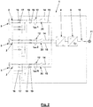
- the inverter 1 shown has a plurality of connections 2 each for a photovoltaic generator 3 as a specific example of a direct current generator.
- the photovoltaic generators 3 are connected in parallel in stages, so that their output voltages are always the same and correspond to an input-side intermediate circuit voltage of an input-side DC / DC converter 4 of the inverter 1.
- This DC / DC converter defines an intermediate circuit voltage across a DC voltage intermediate circuit 5, which is designed here with a grounded center point 6 and two capacitors 7, from which a three-phase DC / AC converter 8 of the inverter 1 is fed.
- the DC / AC converter 8 is connected to an alternating current network 11 via a line filter 9 and a line switch 10.
- differential current sensors 12 To monitor the inverter 1 for the occurrence of critical fault currents, which give an indication of earth faults in the area of the photovoltaic generators 3 and their parallel connection, several differential current sensors 12 are provided, with each of which the differential current is detected via a pair of input lines 14, 15. These input lines 14, 15 carry the current from two photovoltaic generators each, whereby even more photovoltaic generators can be connected to each pair of input lines 14, 15, but also only a single photovoltaic generator 3.
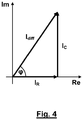
- the differential current I diff measured with each of the differential current sensors 12 is checked separately from the other differential currents to determine whether it has a short-term increase above a limit value. This check can be carried out directly on the differential current I diff or on its resistive fault current component I R.
- This resistive fault current component is the real part of the differential current I diff , ie the current that is in phase with the voltage.
- a capacitive leakage current component I C is the imaginary part of the differential current I diff , which has a phase offset of 90 ° to the voltage.
- the capacitive leakage current is approximately due to the large capacities of the photovoltaic generators with respect to earth for each differential current sensor 1 N reduced, where N is the number of differential current sensors.
- the sensitivity in the monitoring of the total differential current with regard to the detection of a relevant increase in the fault current component I R is improved by a factor N.
- the sum of the differential currents ⁇ I diff i is determined, where I diff i with i from 1 to N are the differential currents from the individual differential current sensors 12, and compared with a further limit value. This can be done by directly comparing the sum ⁇ I diff i with the further limit value. However, a current component of the sum of the differential currents I diff measured at the same time can also be compared with the further limit value. This current component of the sum of the simultaneously measured differential currents I diff can be determined from the sum ⁇ I diff i itself or as the sum of the corresponding current components of the individual differential currents I diff i. In a preferred embodiment, the current component can also be the capacitive leakage current component I C instead of the fault current component I R.
- differential current sensors 12 are provided in the inverter 1 with which the differential current I diff flowing via a pair of input lines 14, 15 of three or more photovoltaic generators 3 is detected.
- the photovoltaic generators 3 in the inverter 1 are each individually protected by a pair of fuses 16, 17, additional fuses 18, 19 are arranged in the input lines 14 and 15 here.
- the fuses 16 and 17 can also be arranged outside the inverter 1, for example in a connection unit via which several photovoltaic generators 3 are connected in parallel to a pair of input lines 14 and 15 before they are connected to the connections 2 of the inverter 1 .
- each pair of input lines can be separated individually with a switch 20.
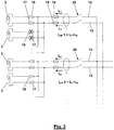
- Fig. 3 illustrates that the differential currents I diff can also be used to detect failures of individual photovoltaic generators.
- both have fuses here 16 and 17 of the second photovoltaic generator 3 triggered, so that the photovoltaic generator 3 is no longer connected to the input lines 14 and 15.
- This eliminates the leakage capacitance of the second photovoltaic generator 3 and thus a substantial part of the capacitive leakage current component of the fault current I diff 1.
- the triggering of only one of the fuses 16 and 17 reduces the capacitive leakage current component of the fault current I diff 1. Even if this reduction is smaller than for If both fuses 16 and 17 are triggered, it becomes significant when comparing the differential current I diff 1 with the differential current I diff 2, which is measured at the same time for photovoltaic generators 3 that have not failed.
Landscapes
- Engineering & Computer Science (AREA)
- Power Engineering (AREA)
- General Physics & Mathematics (AREA)
- Physics & Mathematics (AREA)
- Sustainable Energy (AREA)
- Sustainable Development (AREA)
- Condensed Matter Physics & Semiconductors (AREA)
- Electromagnetism (AREA)
- Life Sciences & Earth Sciences (AREA)
- Computer Hardware Design (AREA)
- Microelectronics & Electronic Packaging (AREA)
- Inverter Devices (AREA)
- Emergency Protection Circuit Devices (AREA)
- Photovoltaic Devices (AREA)
- Testing Of Short-Circuits, Discontinuities, Leakage, Or Incorrect Line Connections (AREA)
- Protection Of Static Devices (AREA)
Claims (15)
- Procédé de surveillance d'un onduleur (1) avec des bornes (2) séparées du côté de l'entrée pour plusieurs générateurs de courant continu en cas d'apparition d'un courant de défaut critique (IR),- dans lequel des courants différentiels (Idiff) entre les lignes d'entrée (14, 15) sont mesurés dans l'onduleur (1), lesdites lignes d'entrée (14, 15) transportant dans leur totalité tous les courants injectés aux bornes individuelles (2), et- dans lequel les courants différentiels (Idiff) sont comparés à une valeur limite, un défaut étant détecté si la valeur limite est dépassée,caractérisé en ce que- les courants différentiels (Idiff) dans l'onduleur (1) sont mesurés séparément par l'intermédiaire d'au moins deux paires de lignes d'entrée (14, 15), ces au moins deux paires de lignes d'entrée (14, 15) transportant les courants injectés sur différentes bornes côté entrée (2) ;- les courants différentiels (Idiff) pour chaque paire de lignes d'entrée (14, 15) sont comparés séparément à la valeur limite ; et- en outre, une somme des courants différentiels (Idiff) mesurés séparément et simultanément sur toutes les paires de lignes d'entrée (14, 15) est déterminée et comparée à une autre valeur limite, un défaut étant également détecté si l'autre valeur limite est dépassée.
- Procédé selon la revendication 1, caractérisé en ce que la valeur limite à laquelle les courants différentiels (Idiff) pour chaque paire de lignes d'entrée (14, 15) sont comparés séparément est une valeur limite pour une augmentation de courant dans un certain temps.
- Procédé selon la revendication 1 ou 2, caractérisé en ce que la valeur limite à laquelle les courants différentiels (Idiff) pour chaque paire de lignes d'entrée (14, 15) sont comparés séparément est une valeur limite pour une augmentation d'une composante de courant de défaut résistif (IR) des courants différentiels (Idiff), dans lequel, facultativement, pour chacun des courants différentiels mesurés (Idiff), sa composante de courant de défaut résistif (IR) est déterminée et chacun des courants différentiels mesurés (Idiff) est comparé sous la forme de sa composante de courant de défaut résistif (IR) à la valeur limite.
- Procédé selon l'une quelconque des revendications précédentes, caractérisé en ce que l'autre valeur limite à laquelle est comparée la somme des courants différentiels (Idiff) mesurés simultanément et séparément sur toutes les paires de lignes d'entrée (14, 15) est une valeur limite pour une somme des composantes de courant de fuite capacitif (IC) des courants différentiels (Idiff).
- Procédé selon la revendication 4, caractérisé en ce que- soit la composante de courant de fuite capacitif (IC) de chacun des courants différentiels mesurés (Idiff) est déterminée, et en ce que la somme des courants différentiels (Idiff) mesurés séparément et simultanément sur toutes les paires de lignes d'entrée (14, 15) est déterminée sous la forme de la somme de leurs composantes de courant de fuite capacitif (IC) et est comparée à l'autre valeur limite,- soit la somme des courants différentiels (Idiff) mesurés simultanément et séparément sur toutes les paires de lignes d'entrée (14, 15) est déterminée sous la forme d'une composante de courant de fuite capacitif de la somme des courants différentiels (Idiff) mesurés simultanément et séparément et est comparée à l'autre valeur limite.
- Procédé selon l'une quelconque des revendications précédentes, caractérisé en ce que chaque paire de lignes d'entrée (14, 15) véhicule les courants injectés aux bornes (2) pour au moins deux générateurs de courant continu.
- Procédé selon l'une quelconque des revendications précédentes, caractérisé en ce que l'onduleur (1) est mis hors tension et/ou déconnecté d'un réseau alternatif (11) connecté du côté de la sortie lorsqu'un défaut est détecté.
- Procédé selon l'une quelconque des revendications précédentes, caractérisé en ce que lorsqu'un défaut est détecté sur une seule paire de lignes d'entrée (14, 15), on déconnecte sélectivement lesdites lignes d'entrée (14, 15) ou on déconnecte sélectivement les bornes associées (2).
- Procédé selon l'une quelconque des revendications précédentes, caractérisé en ce qu'une chute du courant différentiel (Idiff) à travers une paire de lignes d'entrée (14, 15) est évaluée comme une indication d'une défaillance d'un générateur de courant continu qui y est connecté.
- Procédé selon l'une quelconque des revendications précédentes, caractérisé en ce que, en outre, les courants différentiels (Idiff) mesurés séparément et simultanément sur les au moins deux paires de lignes d'entrée (14, 15) sont comparés les uns aux autres, dans lequel, éventuellement, des évolutions à long terme des courants différentiels (Idiff) sur les au moins deux paires de lignes d'entrée (14, 15) sont évaluées.
- Onduleur (1) pour la mise en oeuvre du procédé selon l'une des revendications précédentes avec :- des bornes séparées côté entrée (2) pour plusieurs générateurs de courant continu,- des moyens de mesure des courants différentiels (Idiff) entre les lignes d'entrée (14, 15) transportant dans leur totalité les courants injectés aux bornes (2), et- des dispositifs de surveillance qui comparent les courants différentiels (Idiff) avec une valeur limite et détectent un défaut si la valeur limite est dépassée,caractérisé en ce que- les dispositifs de mesure présentent un capteur de courant différentiel (12) séparé pour chacune d'au moins deux paires de lignes d'entrée (14, 15), ces au moins deux paires de lignes d'entrée (14, 15) transportant les courants injectés sur différentes bornes côté entrée (2) ;- les dispositifs de surveillance comparent séparément les courants différentiels (Idiff) mesurés avec chacun des capteurs de courant différentiel (12) avec la valeur limite ; et- les dispositifs de surveillance déterminent en outre une somme des courants différentiels (Idiff) mesurés séparément en même temps avec tous les capteurs de courant différentiel séparés (12) et la comparent à une autre valeur limite et détectent également un défaut si l'autre valeur limite est dépassée.
- Onduleur selon la revendication 11, caractérisé en ce que les moyens de surveillance déterminent pour chacun des courants différentiels (Idiff) mesurés avec l'un des capteurs de courant différentiel (12) sa composante de courant de défaut résistif (IR), dans lequel les moyens de surveillance comparent facultativement chacun des courants différentiels mesurés (Idiff) sous la forme de sa composante de courant de défaut résistif (IR) avec la valeur limite.
- Onduleur selon la revendication 11 ou 12, caractérisé en ce que les moyens de surveillance déterminent pour chacun des courants différentiels (Idiff) mesurés avec l'un des capteurs de courant différentiel (12) sa composante de courant de fuite capacitif (IC), dans lequel les moyens de surveillance déterminent facultativement la somme des courants différentiels (Idiff) mesurés simultanément séparément sur toutes les paires de lignes d'entrée (14, 15) sous la forme de la somme de leurs composantes de courant de fuite capacitif (IC) et la comparent à la valeur limite supplémentaire.
- Onduleur selon la revendication 11 ou 12, caractérisé en ce que les moyens de surveillance déterminent la somme des courants différentiels (Idiff) apparaissant simultanément sur toutes les paires de lignes d'entrée (14, 15) sous la forme d'une composante de courant de fuite capacitif de la somme des courants différentiels (Idiff) mesurés simultanément et séparément et la comparent à l'autre valeur limite.
- Onduleur selon l'une quelconque des revendications 11 à 14, caractérisé en ce que chaque paire de lignes d'entrée (14, 15) véhicule les courants injectés aux bornes (2) pour au moins deux générateurs de courant continu.
Applications Claiming Priority (2)
| Application Number | Priority Date | Filing Date | Title |
|---|---|---|---|
| DE102012107126 | 2012-08-03 | ||
| PCT/EP2013/065182 WO2014019864A1 (fr) | 2012-08-03 | 2013-07-18 | Détection de courant résiduel et courant de fuite distribué ainsi que identification d'erreurs en chaîne |
Publications (2)
| Publication Number | Publication Date |
|---|---|
| EP2880454A1 EP2880454A1 (fr) | 2015-06-10 |
| EP2880454B1 true EP2880454B1 (fr) | 2021-06-30 |
Family
ID=48877216
Family Applications (1)
| Application Number | Title | Priority Date | Filing Date |
|---|---|---|---|
| EP13742186.3A Active EP2880454B1 (fr) | 2012-08-03 | 2013-07-18 | Détection de courant de fuite et de defaut et détection d'un défaut d'un string |
Country Status (6)
| Country | Link |
|---|---|
| US (1) | US9594126B2 (fr) |
| EP (1) | EP2880454B1 (fr) |
| JP (1) | JP6195091B2 (fr) |
| CN (1) | CN104704378B (fr) |
| DE (1) | DE112013003857A5 (fr) |
| WO (1) | WO2014019864A1 (fr) |
Families Citing this family (7)
| Publication number | Priority date | Publication date | Assignee | Title |
|---|---|---|---|---|
| ES2623789T3 (es) * | 2013-07-18 | 2017-07-12 | Sma Solar Technology Ag | Procedimiento y disposición de circuito con medios para compensar la corriente de fuga en una instalación fotovoltaica con varios sensores de corriente diferencia |
| US20150288188A1 (en) * | 2014-04-08 | 2015-10-08 | Marvin S Keshner | Parallel-Connected Solar Electric System |
| KR101803132B1 (ko) * | 2014-04-28 | 2017-11-29 | 엘에스산전 주식회사 | 무 변압기형 태양광 인버터의 누설전류 감시 장치 |
| IT201700032303A1 (it) * | 2017-03-23 | 2018-09-23 | St Microelectronics Srl | Procedimento di funzionamento di generatori fotovoltaici, circuito, dispositivo e sistema corrispondenti |
| JP7204450B2 (ja) * | 2018-11-29 | 2023-01-16 | 株式会社Nttファシリティーズ | 絶縁抵抗試験システム及び絶縁抵抗試験方法 |
| DE102020115757A1 (de) | 2020-06-15 | 2021-12-16 | Sma Solar Technology Ag | Vorrichtung und verfahren zur detektion eines fehlerstroms in einer photovoltaik-anlage, sowie photovoltaik-wechselrichter mit der vorrichtung |
| CN111934280B (zh) * | 2020-09-09 | 2023-01-24 | 南方电网数字电网研究院有限公司 | 漏电故障检测方法、装置、存储介质和配电网关 |
Family Cites Families (12)
| Publication number | Priority date | Publication date | Assignee | Title |
|---|---|---|---|---|
| JP2874156B2 (ja) * | 1994-04-13 | 1999-03-24 | キヤノン株式会社 | 発電システム |
| JPH09285015A (ja) * | 1996-04-08 | 1997-10-31 | Sanyo Electric Co Ltd | 太陽光発電システムの直流地絡検出装置 |
| JP2002233045A (ja) | 2001-02-02 | 2002-08-16 | Canon Inc | 太陽光発電システムの地絡検出のための装置及び方法 |
| US7768751B2 (en) * | 2008-01-29 | 2010-08-03 | Advanced Energy Industries, Inc. | System and method for ground fault detection and interruption |
| JP2010114150A (ja) | 2008-11-04 | 2010-05-20 | Sharp Corp | 太陽光発電システム |
| EP2293089A1 (fr) | 2009-09-02 | 2011-03-09 | SMA Solar Technology AG | Surveillance de panne de chaîne |
| US8335062B2 (en) * | 2010-03-08 | 2012-12-18 | Pass & Seymour, Inc. | Protective device for an electrical supply facility |
| ES2565005T3 (es) * | 2010-03-31 | 2016-03-30 | Sma Solar Technology Ag | Determinación de la parte de corriente de falta de una corriente diferencial |
| DE102010036816A1 (de) | 2010-08-03 | 2012-02-09 | Newtos Ag | Verfahren und Vorrichtung zur Überwachung und Steuerung einer Photovoltaik-Anlage |
| US8659858B2 (en) * | 2010-08-24 | 2014-02-25 | Sanyo Electric Co., Ltd. | Ground-fault detecting device, current collecting box using the ground-fault detecting device, and photovoltaic power generating device using the current collecting box |
| US20120049627A1 (en) * | 2010-08-24 | 2012-03-01 | Sanyo Electric Co., Ltd. | Current collecting box for photovoltaic power generation |
| DE102011002084A1 (de) | 2011-04-15 | 2012-10-18 | Sma Solar Technology Ag | Verfahren und Vorrichtung zur Bestimmung eines Fehlerstromanteils an einem Differenzstrom |
-
2013
- 2013-07-18 EP EP13742186.3A patent/EP2880454B1/fr active Active
- 2013-07-18 WO PCT/EP2013/065182 patent/WO2014019864A1/fr active Application Filing
- 2013-07-18 JP JP2015524711A patent/JP6195091B2/ja active Active
- 2013-07-18 DE DE112013003857.9T patent/DE112013003857A5/de active Pending
- 2013-07-18 CN CN201380052122.9A patent/CN104704378B/zh active Active
-
2015
- 2015-01-28 US US14/607,151 patent/US9594126B2/en active Active
Non-Patent Citations (1)
| Title |
|---|
| None * |
Also Published As
| Publication number | Publication date |
|---|---|
| US20150137850A1 (en) | 2015-05-21 |
| JP6195091B2 (ja) | 2017-09-13 |
| US9594126B2 (en) | 2017-03-14 |
| WO2014019864A1 (fr) | 2014-02-06 |
| DE112013003857A5 (de) | 2015-04-23 |
| CN104704378B (zh) | 2017-09-19 |
| JP2015531859A (ja) | 2015-11-05 |
| EP2880454A1 (fr) | 2015-06-10 |
| CN104704378A (zh) | 2015-06-10 |
Similar Documents
| Publication | Publication Date | Title |
|---|---|---|
| EP2880454B1 (fr) | Détection de courant de fuite et de defaut et détection d'un défaut d'un string | |
| EP2230522B1 (fr) | Procédé et dispositif de surveillance d'isolation d'un réseau isolé terre | |
| EP3394948B1 (fr) | Onduleur à point de rupture de réseau et mesure de résistance d'isolement et procédé de mesure d'une résistance d'isolement | |
| EP2817828B1 (fr) | Protection de modules photovoltaïques d'un générateur photovoltaïque contre des surtensions par rapport à la terre | |
| EP2205984B1 (fr) | Montage destiné à surveiller une isolation électrique | |
| DE102013213301A1 (de) | Erdschlusserfassungseinrichtung für eine ungeerdete Schaltung | |
| EP3631976B1 (fr) | Procédé servant à identifier un contact défectueux dans une installation photovoltaïque | |
| EP2887081B1 (fr) | Dispositif destiné à la surveillance d'isolation | |
| EP3022814B1 (fr) | Procédé et circuiterie pourvue de moyens de compensation de courant de fuite dans une installation photovoltaïque comprenant plusieurs capteurs de courant différentiel | |
| WO2015121082A1 (fr) | Système et procédé de gestion d'une batterie à plusieurs éléments | |
| DE102014117417A1 (de) | Schaltzustandsüberprüfung mit Schaltungsteilen eines Isolationswächters | |
| DE102016121453A1 (de) | Fehleruntersuchungssystem, das eine Unterscheidung zwischen einem Leckstromfehler und einem Kurzschlussfehler ermöglicht | |
| DE102016113624B4 (de) | Motorantrieb mit Funktion zum Detektieren von Schaltungsabnormalitäten aufgrund eindringender Fremdstoffe, bevor es zu einer erheblichen Abnormalität kommt | |
| EP0795222A1 (fr) | Procede de detection d'un defaut a la terre dans une ligne de transmission d'energie electrique | |
| EP3723220B1 (fr) | Emplacements d'une perte à la terre dans un réseau à courant continue | |
| EP2181337A1 (fr) | Dispositif de détection d'une asymétrie de charge dans un réseau triphasé | |
| EP3832324A1 (fr) | Agencement de circuit à tension de mesure active permettant de déterminer la résistance d'isolation par rapport à la terre dans un système d'alimentation en courant non mis à la terre | |
| EP3451477A1 (fr) | Détection d'une erreur dans un système de transmission de courant continu | |
| EP3931926A1 (fr) | Détection d'un défaut à la terre dans un réseau à tension continue | |
| DE4418124C2 (de) | Vorrichtung zum Erkennen einer Isolationsverschlechterung an Stromversorgungsleitungen | |
| DE102012211092A1 (de) | Batteriesystem und Kraftfahrzeug mit Batteriesystem | |
| DE19640821B4 (de) | Verfahren und Einrichtung zur Erfassung von Erdschlüssen | |
| WO2012045103A1 (fr) | Unité de détection pour détecter une rupture de conducteur neutre dans un réseau de courant polyphasé symétrique | |
| DE102020115757A1 (de) | Vorrichtung und verfahren zur detektion eines fehlerstroms in einer photovoltaik-anlage, sowie photovoltaik-wechselrichter mit der vorrichtung | |
| DE102020102177A1 (de) | Elektrische Energiespeichervorrichtung sowie Verfahren zum Betreiben einer elektrischen Energiespeichervorrichtung |
Legal Events
| Date | Code | Title | Description |
|---|---|---|---|
| PUAI | Public reference made under article 153(3) epc to a published international application that has entered the european phase |
Free format text: ORIGINAL CODE: 0009012 |
|
| 17P | Request for examination filed |
Effective date: 20150220 |
|
| AK | Designated contracting states |
Kind code of ref document: A1 Designated state(s): AL AT BE BG CH CY CZ DE DK EE ES FI FR GB GR HR HU IE IS IT LI LT LU LV MC MK MT NL NO PL PT RO RS SE SI SK SM TR |
|
| AX | Request for extension of the european patent |
Extension state: BA ME |
|
| DAX | Request for extension of the european patent (deleted) | ||
| STAA | Information on the status of an ep patent application or granted ep patent |
Free format text: STATUS: EXAMINATION IS IN PROGRESS |
|
| 17Q | First examination report despatched |
Effective date: 20180212 |
|
| REG | Reference to a national code |
Ref country code: DE Ref legal event code: R079 Ref document number: 502013015801 Country of ref document: DE Free format text: PREVIOUS MAIN CLASS: G01R0031020000 Ipc: G01R0031520000 |
|
| RIC1 | Information provided on ipc code assigned before grant |
Ipc: H02S 50/10 20140101ALI20201217BHEP Ipc: G01R 31/52 20200101AFI20201217BHEP Ipc: G01R 31/40 20200101ALI20201217BHEP Ipc: H01L 31/02 20060101ALI20201217BHEP Ipc: H02S 50/00 20140101ALI20201217BHEP Ipc: H02H 7/20 20060101ALN20201217BHEP Ipc: H02H 3/33 20060101ALI20201217BHEP |
|
| GRAP | Despatch of communication of intention to grant a patent |
Free format text: ORIGINAL CODE: EPIDOSNIGR1 |
|
| STAA | Information on the status of an ep patent application or granted ep patent |
Free format text: STATUS: GRANT OF PATENT IS INTENDED |
|
| INTG | Intention to grant announced |
Effective date: 20210122 |
|
| GRAS | Grant fee paid |
Free format text: ORIGINAL CODE: EPIDOSNIGR3 |
|
| GRAA | (expected) grant |
Free format text: ORIGINAL CODE: 0009210 |
|
| STAA | Information on the status of an ep patent application or granted ep patent |
Free format text: STATUS: THE PATENT HAS BEEN GRANTED |
|
| RIN1 | Information on inventor provided before grant (corrected) |
Inventor name: WILLENBERG, MARIO Inventor name: FALK, ANDREAS |
|
| AK | Designated contracting states |
Kind code of ref document: B1 Designated state(s): AL AT BE BG CH CY CZ DE DK EE ES FI FR GB GR HR HU IE IS IT LI LT LU LV MC MK MT NL NO PL PT RO RS SE SI SK SM TR |
|
| REG | Reference to a national code |
Ref country code: GB Ref legal event code: FG4D Free format text: NOT ENGLISH Ref country code: CH Ref legal event code: EP |
|
| REG | Reference to a national code |
Ref country code: AT Ref legal event code: REF Ref document number: 1406820 Country of ref document: AT Kind code of ref document: T Effective date: 20210715 |
|
| REG | Reference to a national code |
Ref country code: DE Ref legal event code: R096 Ref document number: 502013015801 Country of ref document: DE |
|
| REG | Reference to a national code |
Ref country code: IE Ref legal event code: FG4D Free format text: LANGUAGE OF EP DOCUMENT: GERMAN |
|
| REG | Reference to a national code |
Ref country code: NL Ref legal event code: FP |
|
| REG | Reference to a national code |
Ref country code: LT Ref legal event code: MG9D |
|
| PG25 | Lapsed in a contracting state [announced via postgrant information from national office to epo] |
Ref country code: BG Free format text: LAPSE BECAUSE OF FAILURE TO SUBMIT A TRANSLATION OF THE DESCRIPTION OR TO PAY THE FEE WITHIN THE PRESCRIBED TIME-LIMIT Effective date: 20210930 Ref country code: HR Free format text: LAPSE BECAUSE OF FAILURE TO SUBMIT A TRANSLATION OF THE DESCRIPTION OR TO PAY THE FEE WITHIN THE PRESCRIBED TIME-LIMIT Effective date: 20210630 Ref country code: FI Free format text: LAPSE BECAUSE OF FAILURE TO SUBMIT A TRANSLATION OF THE DESCRIPTION OR TO PAY THE FEE WITHIN THE PRESCRIBED TIME-LIMIT Effective date: 20210630 |
|
| PG25 | Lapsed in a contracting state [announced via postgrant information from national office to epo] |
Ref country code: LV Free format text: LAPSE BECAUSE OF FAILURE TO SUBMIT A TRANSLATION OF THE DESCRIPTION OR TO PAY THE FEE WITHIN THE PRESCRIBED TIME-LIMIT Effective date: 20210630 Ref country code: GR Free format text: LAPSE BECAUSE OF FAILURE TO SUBMIT A TRANSLATION OF THE DESCRIPTION OR TO PAY THE FEE WITHIN THE PRESCRIBED TIME-LIMIT Effective date: 20211001 Ref country code: NO Free format text: LAPSE BECAUSE OF FAILURE TO SUBMIT A TRANSLATION OF THE DESCRIPTION OR TO PAY THE FEE WITHIN THE PRESCRIBED TIME-LIMIT Effective date: 20210930 Ref country code: RS Free format text: LAPSE BECAUSE OF FAILURE TO SUBMIT A TRANSLATION OF THE DESCRIPTION OR TO PAY THE FEE WITHIN THE PRESCRIBED TIME-LIMIT Effective date: 20210630 Ref country code: SE Free format text: LAPSE BECAUSE OF FAILURE TO SUBMIT A TRANSLATION OF THE DESCRIPTION OR TO PAY THE FEE WITHIN THE PRESCRIBED TIME-LIMIT Effective date: 20210630 |
|
| PG25 | Lapsed in a contracting state [announced via postgrant information from national office to epo] |
Ref country code: SM Free format text: LAPSE BECAUSE OF FAILURE TO SUBMIT A TRANSLATION OF THE DESCRIPTION OR TO PAY THE FEE WITHIN THE PRESCRIBED TIME-LIMIT Effective date: 20210630 Ref country code: SK Free format text: LAPSE BECAUSE OF FAILURE TO SUBMIT A TRANSLATION OF THE DESCRIPTION OR TO PAY THE FEE WITHIN THE PRESCRIBED TIME-LIMIT Effective date: 20210630 Ref country code: CZ Free format text: LAPSE BECAUSE OF FAILURE TO SUBMIT A TRANSLATION OF THE DESCRIPTION OR TO PAY THE FEE WITHIN THE PRESCRIBED TIME-LIMIT Effective date: 20210630 Ref country code: EE Free format text: LAPSE BECAUSE OF FAILURE TO SUBMIT A TRANSLATION OF THE DESCRIPTION OR TO PAY THE FEE WITHIN THE PRESCRIBED TIME-LIMIT Effective date: 20210630 Ref country code: PT Free format text: LAPSE BECAUSE OF FAILURE TO SUBMIT A TRANSLATION OF THE DESCRIPTION OR TO PAY THE FEE WITHIN THE PRESCRIBED TIME-LIMIT Effective date: 20211102 Ref country code: RO Free format text: LAPSE BECAUSE OF FAILURE TO SUBMIT A TRANSLATION OF THE DESCRIPTION OR TO PAY THE FEE WITHIN THE PRESCRIBED TIME-LIMIT Effective date: 20210630 Ref country code: ES Free format text: LAPSE BECAUSE OF FAILURE TO SUBMIT A TRANSLATION OF THE DESCRIPTION OR TO PAY THE FEE WITHIN THE PRESCRIBED TIME-LIMIT Effective date: 20210630 |
|
| PG25 | Lapsed in a contracting state [announced via postgrant information from national office to epo] |
Ref country code: PL Free format text: LAPSE BECAUSE OF FAILURE TO SUBMIT A TRANSLATION OF THE DESCRIPTION OR TO PAY THE FEE WITHIN THE PRESCRIBED TIME-LIMIT Effective date: 20210630 |
|
| REG | Reference to a national code |
Ref country code: CH Ref legal event code: PL |
|
| REG | Reference to a national code |
Ref country code: DE Ref legal event code: R097 Ref document number: 502013015801 Country of ref document: DE |
|
| PG25 | Lapsed in a contracting state [announced via postgrant information from national office to epo] |
Ref country code: MC Free format text: LAPSE BECAUSE OF FAILURE TO SUBMIT A TRANSLATION OF THE DESCRIPTION OR TO PAY THE FEE WITHIN THE PRESCRIBED TIME-LIMIT Effective date: 20210630 |
|
| PG25 | Lapsed in a contracting state [announced via postgrant information from national office to epo] |
Ref country code: LI Free format text: LAPSE BECAUSE OF NON-PAYMENT OF DUE FEES Effective date: 20210731 Ref country code: DK Free format text: LAPSE BECAUSE OF FAILURE TO SUBMIT A TRANSLATION OF THE DESCRIPTION OR TO PAY THE FEE WITHIN THE PRESCRIBED TIME-LIMIT Effective date: 20210630 Ref country code: CH Free format text: LAPSE BECAUSE OF NON-PAYMENT OF DUE FEES Effective date: 20210731 |
|
| PLBE | No opposition filed within time limit |
Free format text: ORIGINAL CODE: 0009261 |
|
| STAA | Information on the status of an ep patent application or granted ep patent |
Free format text: STATUS: NO OPPOSITION FILED WITHIN TIME LIMIT |
|
| PG25 | Lapsed in a contracting state [announced via postgrant information from national office to epo] |
Ref country code: LU Free format text: LAPSE BECAUSE OF NON-PAYMENT OF DUE FEES Effective date: 20210718 Ref country code: AL Free format text: LAPSE BECAUSE OF FAILURE TO SUBMIT A TRANSLATION OF THE DESCRIPTION OR TO PAY THE FEE WITHIN THE PRESCRIBED TIME-LIMIT Effective date: 20210630 |
|
| 26N | No opposition filed |
Effective date: 20220331 |
|
| PG25 | Lapsed in a contracting state [announced via postgrant information from national office to epo] |
Ref country code: IE Free format text: LAPSE BECAUSE OF NON-PAYMENT OF DUE FEES Effective date: 20210718 |
|
| REG | Reference to a national code |
Ref country code: AT Ref legal event code: MM01 Ref document number: 1406820 Country of ref document: AT Kind code of ref document: T Effective date: 20210718 |
|
| PG25 | Lapsed in a contracting state [announced via postgrant information from national office to epo] |
Ref country code: AT Free format text: LAPSE BECAUSE OF NON-PAYMENT OF DUE FEES Effective date: 20210718 |
|
| PG25 | Lapsed in a contracting state [announced via postgrant information from national office to epo] |
Ref country code: LT Free format text: LAPSE BECAUSE OF FAILURE TO SUBMIT A TRANSLATION OF THE DESCRIPTION OR TO PAY THE FEE WITHIN THE PRESCRIBED TIME-LIMIT Effective date: 20210630 |
|
| PG25 | Lapsed in a contracting state [announced via postgrant information from national office to epo] |
Ref country code: HU Free format text: LAPSE BECAUSE OF FAILURE TO SUBMIT A TRANSLATION OF THE DESCRIPTION OR TO PAY THE FEE WITHIN THE PRESCRIBED TIME-LIMIT; INVALID AB INITIO Effective date: 20130718 |
|
| PG25 | Lapsed in a contracting state [announced via postgrant information from national office to epo] |
Ref country code: CY Free format text: LAPSE BECAUSE OF FAILURE TO SUBMIT A TRANSLATION OF THE DESCRIPTION OR TO PAY THE FEE WITHIN THE PRESCRIBED TIME-LIMIT Effective date: 20210630 |
|
| P01 | Opt-out of the competence of the unified patent court (upc) registered |
Effective date: 20230614 |
|
| PGFP | Annual fee paid to national office [announced via postgrant information from national office to epo] |
Ref country code: NL Payment date: 20230720 Year of fee payment: 11 |
|
| PGFP | Annual fee paid to national office [announced via postgrant information from national office to epo] |
Ref country code: IT Payment date: 20230731 Year of fee payment: 11 Ref country code: GB Payment date: 20230724 Year of fee payment: 11 |
|
| PGFP | Annual fee paid to national office [announced via postgrant information from national office to epo] |
Ref country code: FR Payment date: 20230724 Year of fee payment: 11 Ref country code: DE Payment date: 20230720 Year of fee payment: 11 Ref country code: BE Payment date: 20230719 Year of fee payment: 11 |
|
| PG25 | Lapsed in a contracting state [announced via postgrant information from national office to epo] |
Ref country code: MK Free format text: LAPSE BECAUSE OF FAILURE TO SUBMIT A TRANSLATION OF THE DESCRIPTION OR TO PAY THE FEE WITHIN THE PRESCRIBED TIME-LIMIT Effective date: 20210630 |