EP0665185B1 - Grue, en particulier pour voie ferrée - Google Patents
Grue, en particulier pour voie ferrée Download PDFInfo
- Publication number
- EP0665185B1 EP0665185B1 EP94250298A EP94250298A EP0665185B1 EP 0665185 B1 EP0665185 B1 EP 0665185B1 EP 94250298 A EP94250298 A EP 94250298A EP 94250298 A EP94250298 A EP 94250298A EP 0665185 B1 EP0665185 B1 EP 0665185B1
- Authority
- EP
- European Patent Office
- Prior art keywords
- vehicle frame
- crane according
- crane
- piston
- lifting
- Prior art date
- Legal status (The legal status is an assumption and is not a legal conclusion. Google has not performed a legal analysis and makes no representation as to the accuracy of the status listed.)
- Expired - Lifetime
Links
- 239000007788 liquid Substances 0.000 claims description 6
- 230000007480 spreading Effects 0.000 claims description 5
- 230000007246 mechanism Effects 0.000 description 6
- 230000005484 gravity Effects 0.000 description 3
- 239000000872 buffer Substances 0.000 description 1
- 238000010276 construction Methods 0.000 description 1
- 230000006872 improvement Effects 0.000 description 1
- XLYOFNOQVPJJNP-UHFFFAOYSA-N water Substances O XLYOFNOQVPJJNP-UHFFFAOYSA-N 0.000 description 1
Images


Classifications
-
- B—PERFORMING OPERATIONS; TRANSPORTING
- B61—RAILWAYS
- B61D—BODY DETAILS OR KINDS OF RAILWAY VEHICLES
- B61D15/00—Other railway vehicles, e.g. scaffold cars; Adaptations of vehicles for use on railways
- B61D15/02—Breakdown cranes
-
- B—PERFORMING OPERATIONS; TRANSPORTING
- B66—HOISTING; LIFTING; HAULING
- B66C—CRANES; LOAD-ENGAGING ELEMENTS OR DEVICES FOR CRANES, CAPSTANS, WINCHES, OR TACKLES
- B66C23/00—Cranes comprising essentially a beam, boom, or triangular structure acting as a cantilever and mounted for translatory of swinging movements in vertical or horizontal planes or a combination of such movements, e.g. jib-cranes, derricks, tower cranes
- B66C23/18—Cranes comprising essentially a beam, boom, or triangular structure acting as a cantilever and mounted for translatory of swinging movements in vertical or horizontal planes or a combination of such movements, e.g. jib-cranes, derricks, tower cranes specially adapted for use in particular purposes
- B66C23/36—Cranes comprising essentially a beam, boom, or triangular structure acting as a cantilever and mounted for translatory of swinging movements in vertical or horizontal planes or a combination of such movements, e.g. jib-cranes, derricks, tower cranes specially adapted for use in particular purposes mounted on road or rail vehicles; Manually-movable jib-cranes for use in workshops; Floating cranes
- B66C23/50—Cranes comprising essentially a beam, boom, or triangular structure acting as a cantilever and mounted for translatory of swinging movements in vertical or horizontal planes or a combination of such movements, e.g. jib-cranes, derricks, tower cranes specially adapted for use in particular purposes mounted on road or rail vehicles; Manually-movable jib-cranes for use in workshops; Floating cranes mounted on railway vehicles, e.g. breakdown cranes
-
- B—PERFORMING OPERATIONS; TRANSPORTING
- B66—HOISTING; LIFTING; HAULING
- B66C—CRANES; LOAD-ENGAGING ELEMENTS OR DEVICES FOR CRANES, CAPSTANS, WINCHES, OR TACKLES
- B66C23/00—Cranes comprising essentially a beam, boom, or triangular structure acting as a cantilever and mounted for translatory of swinging movements in vertical or horizontal planes or a combination of such movements, e.g. jib-cranes, derricks, tower cranes
- B66C23/62—Constructional features or details
- B66C23/84—Slewing gear
Definitions
- the invention relates to a crane, in particular a rail-bound mobile crane, such as e.g. a railway crane, with a luffing jib, which is mounted on the (vehicle) frame so that it can be swiveled up and down about a horizontal axis and can be rotated about a vertical axis.
- a rail-bound mobile crane such as e.g. a railway crane
- a luffing jib which is mounted on the (vehicle) frame so that it can be swiveled up and down about a horizontal axis and can be rotated about a vertical axis.
- the invention specified in claim 1 is based on the problem of obtaining a large boom length and a high load capacity with a large outreach in a confined space and also allowing lateral lifting with supporting forces that are still permissible, for example on the wheels.
- the side room should here by a safety distance to the neighboring track or a neighboring lane.
- the stated object is achieved according to the invention in the above-mentioned crane in that the luffing jib can be swiveled up or down or raised, supported on at least one swivel bearing arranged at each end of the vehicle frame, by means of a lifting drive arranged between the ends of the vehicle frame.
- the advantages are that the luffing jib can be swiveled up and down to one side or the other, and that the telescopic luffing jib can be swiveled so that it can be swiveled to the left and right in relation to the side view of the crane, and can also be lifted in the middle in parallel, swung to the side can be and can be lifted sideways.
- pivot bearings can each be individually detached or connected to the luffing jib. Depending on the connection created, the pivot bearing in question forms the pivot axis in the horizontal and / or vertical plane.
- the pivot bearings consist of piston-cylinder units each arranged on one end of the vehicle frame and articulated to the luffing jib.
- the pivot bearing itself can thus advantageously be lifted.
- pivot bearings themselves can be rotated about an axis which is vertical on the vehicle frame. If the connection mentioned exists, the luffing jib can therefore be pivoted or rotated about this vertical axis.
- a particularly advantageous embodiment for this rotatability is given in that the piston-cylinder units each telescopic pipe sections is formed with under the ceiling of the inner pipe section engaging piston. On the one hand, this creates a connection option for the luffing jib and, on the other hand, achieves the mentioned rotatability and a space-saving arrangement of the lifting piston.
- connection between the swivel bearing and the luffing jib is advantageously achieved in accordance with further features in that the swivel bearing consists in each case of a side frame part which can be pivoted relative to the piston-cylinder unit and is connected to the luffing jib and is pivotable.
- a loosening or connecting the luffing jib with the swivel bearing is done simply by loosening or inserting the hinge pin, which can be done by hand.
- a further development of the invention consists in that the lifting drive is arranged supported on a slewing gear via a slide plate of the vehicle frame. This essentially enables a pivoting of the luffing jib.
- a horizontal swivel drive is provided for the luffing jib articulated on the lifting drive.
- the horizontal swivel drive is formed from a pinion which is rotatably driven on the rotating mechanism and which engages in a toothed rack extending transversely to the vehicle frame.
- a horizontal swivel drive therefore allows a considerable deflection of the luffing jib from its normal position on both sides of the crane.
- the lifting drive located on the slewing gear can be designed differently.
- An advantageous training is that the The linear actuator consists of two vertical and parallel lifting cylinders attached to the slewing gear, which are held by means of a parallel connection. This initially creates a rigid system for guiding and swinging the luffing jib, and then creates the possibility for further functions.
- One of these functions is that the two lifting cylinders are held on the rotating mechanism about a horizontal, aligned axis.
- the two lifting cylinders can easily follow the swivel movements of the luffing jib.
- a guide frame for the luffing jib is articulated on the piston rods of the lifting cylinder. This creates a load-bearing connection between the luffing jib and the two lifting cylinders or with the slewing gear.
- An improvement of the invention further consists in the fact that pairs of spreading arms which can be pivoted in opposite directions are provided on both sides of the lifting drive, on which support disks are fastened projecting downward. Any changes in the center of gravity caused by the swinging of the luffing jib are thus absorbed.
- ballast tanks for ballast liquids are arranged in the area of a driver's cab on the vehicle frame.
- Such a system has a high degree of flexibility for taking into account the respective focus.
- ballast liquids each from one ballast tank at one end of the vehicle frame to another ballast tank at the other Vehicle frame end are refillable. In this way, the respective center of gravity can be taken into account.
- the crane can be used stationary or as a mobile crane, in particular as a railway crane.
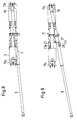
- the railway crane shown has a (vehicle) frame 1, which on bogies 2 with e.g. four wheel sets 3 each rest on the rails. Pairs of buffers 4 and a driver's cab 5 are provided on the vehicle frame 1.
- a luffing jib 6 consisting of a basic boom 7 with a telescopic piece 8, can be swiveled up and down about a horizontal axis 9 and can be rotated and lifted about a vertical axis 10. In the transport state, the luffing jib 6 is firmly connected to the two horizontal axes 9 (FIG. 1A).
- This lifting drive 13 thus forms a rocking cylinder. It is formed from two symmetrically arranged lifting cylinders 13a and 13b with respective piston rods 13c.
- the pivot bearings 12 can each be individually detachably connected to the luffing jib so that the crane can work on both sides of the longitudinal extension of the vehicle frame 1.
- the pivot bearings 12 each consist of piston-cylinder units 14 arranged on a vehicle frame end 11a, 11b, which are formed from telescopic pipe sections 15.
- the pivot bearings 12 are themselves rotatable about the axis 10 perpendicular to the vehicle frame 1.
- a reciprocating piston 16 engages under a ceiling 15a of the inner tube section 15 (FIG. 11).
- the pipe sections 15 can be rotated into one another without having to stress a seal. A slight sliding movement can also take place between the ceiling 15a and the reciprocating piston 16.
- On the swivel bearing 12 laterally extractable hinge pins 17 are provided in side frame parts 18, which are fastened to the basic boom 7. After loosening the hinge pin 17, which is done by hand, a connection with eyes 15b is created opposite the ceiling 15a.
- the lifting drive 13 is supported by a slide plate 19, which is fastened on the vehicle frame 1, and is thus part of a rotating mechanism 20 (FIG. 10).
- a horizontal swivel drive 21 is located on the rotating mechanism 20, so that the lifting drive 13 can be rotated with the luffing jib 6 (FIGS. 7 to 9).
- This horizontal swivel drive 21 is formed from a pinion 22 which is rotatably mounted on the rotating mechanism 20 and which engages in a toothed rack 23 running transversely to the vehicle frame 1.
- the rack 23 has foldable portions 23a, so that the length of the rack 23 can be increased in one or both transverse directions. For example, in FIG. the left section 23a unfolded.
- the lifting drive 13 also has the two lifting cylinders 13a and 13b arranged perpendicularly and parallel to one another, which can additionally be pivoted on the rotating mechanism 20 about horizontal tilting axes 13d by means of tilting bolts 13e.
- the pair of the two lifting cylinders 13a and 13b are connected to each other by means of a parallel connection 24, which is made of a plate or a frame.
- the two tilt axes 13d form an aligned axis 25.
- the piston rods 13c of the lifting cylinders 13a and 13b there is a guide frame 26 for the luffing jib 6, i.e. for its basic boom 7, articulated.
- 1A, 1B, 6 to 9 show that the lifting drive 13 is assigned pairs of spreading arms 27 which can be swiveled in opposite directions on both sides.
- the spreading arms 27 there are supporting discs 28 on downwardly projecting stamps 27, which shift the weight by turning catch the luffing jib 6 (Fig. 8 and 9).
- ballast tanks 29 and 30 which are arranged in the area of a driver's cab 5 on the vehicle frame 1 and which are filled with ballast liquid, e.g. Water that can be filled. Depending on the lifting of the luffing jib 6, the ballast liquid is therefore pumped into one or the other ballast tank 29 or 30 or filled proportionately during transport.
- ballast liquid e.g. Water that can be filled.
Landscapes
- Engineering & Computer Science (AREA)
- Mechanical Engineering (AREA)
- Transportation (AREA)
- Jib Cranes (AREA)
- Machines For Laying And Maintaining Railways (AREA)
- Carriers, Traveling Bodies, And Overhead Traveling Cranes (AREA)
Claims (15)
- Grue, en particulier une grue mobile roulant sur des rails, comportant une flèche articulée qui est montée sur le châssis du véhicule de manière à pourvoir être pivotée vers le haut et vers le bas autour d'un axe horizontal et qui peut tourner autour d'un axe vertical,
caractérisée en ce que la flèche articulée (6), prenant appui sur au moins un palier pivotant (12) agencé à chaque fois à une extrémité (11a,11b) du châssis du véhicule , peut être pivotée vers le haut et vers la bas ou être levée, au moyen d'un dispositif de levage (13) agencé entre les extrémités (11a,11b) du châssis du véhicule. - Grue selon la revendication 1,
caractérisée en ce que les paliers pivotants (12) sont à chaque fois susceptibles d'être déliés ou reliés individuellement à la flèche articulée (6). - Grue selon l'une des revendications 1 ou 2,
caractérisée en ce que les paliers pivotants (12) sont constitués à chaque fois de vérins (14) agencés à une extrémité (11a,11b) du châssis du véhicule et susceptibles d'être reliés de façon articulée à la flèche articulée (6). - Grue selon la revendication 3,
caractérisée en ce que les paliers pivotants (12) peuvent tourner eux-mêmes autour d'un axe (10) vertical sur le châssis du véhicule (1). - Grue selon l'une des revendications 1 à 4,
caractérisée en ce que les vérins (14) sont formés à chaque fois de tronçons de tube (15) télescopiques avec des pistons de levage (16) agissant sous l'enveloppe (15a) du tronçon de tube interne (15). - Grue selon l'une des revendications 1 à 5,
caractérisée en ce que le palier pivotant (12) est constitué à chaque fois d'une partie de châssis latéral (18) pouvant être pivotée autour de tourillons articulés amovibles (17) par rapport au vérin (14) et reliée à la flèche articulée (6) - Grue selon l'une des revendications 1 à 6,
caractérisée en ce que le dispositif de levage (13) est agencé sur une unité rotative (20), en prenant appui sur une plaque coulissante (19) du châssis du véhicule (1). - Grue selon l'une des revendications 1 à 7,
caractérisée en ce que l'on prévoit un entraînement de pivotement horizontal (21) pour la flèche articulée (6) qui est articulée sur le dispositif de levage (13). - Grue selon la revendication 8,
caractérisée en ce que l'entraînement de pivotement horizontal (21) est formé par un pignon (22) monté de façon à pouvoir être entraîné en rotation sur l'unité rotative (20) et agissant dans une tige dentée (23) s'étendant transversalement au châssis du véhicule (1). - Grue selon l'une des revendications 1 à 9,
caractérisée en ce que le dispositif de levage (13) est constitué de deux vérins (13a,13b) fixés verticalement, s'étendant parallèlement sur l'unité rotative (20) et maintenus au moyen d'une liaison parallèle (24). - Grue selon l'une des revendications 1 à 10,
caractérisée en ce que les deux vérins (13a,13b) sont maintenus, autour d'un axe horizontal aligné (25), sur l'unité rotative (20). - Grue selon l'une des revendications 1 à 11,
caractérisée en ce qu'un cadre de guidage (26) pour la flèche articulée (6) est articulé sur les tiges de piston (13c) des vérins (13a,13b). - Grue selon l'une des revendications 1 à 12,
caractérisée en ce que l'on prévoit à chaque fois des paires de bras d'écartement (27) pouvant être pivotés en sens contraire, associées au dispositif de levage (13), et sur lesquels sont fixés des disques d'appui (28) faisant saillie vers le bas. - Grue selon l'une des revendications 1 à 13,
caractérisée en ce que dans la zone d'une cabine de conducteur (5) sur le châssis du véhicule (1) est agencé à chaque fois un réservoir à matière inerte (29,30) pour des liquides de matière inerte. - Grue selon l'une des revendications 1 à 14,
caractérisée en ce que les liquides de matière inerte peuvent être transvasés d'un réservoir à matière inerte (29) à une extrémité (11a) du châssis du véhicule dans un autre réservoir à matière inerte (30) à l'autre extrémité (11b) du châssis du véhicule .
Applications Claiming Priority (2)
| Application Number | Priority Date | Filing Date | Title |
|---|---|---|---|
| DE4403287 | 1994-01-31 | ||
| DE4403287A DE4403287C2 (de) | 1994-01-31 | 1994-01-31 | Schienengebundener Mobilkran |
Publications (2)
| Publication Number | Publication Date |
|---|---|
| EP0665185A1 EP0665185A1 (fr) | 1995-08-02 |
| EP0665185B1 true EP0665185B1 (fr) | 1997-11-12 |
Family
ID=6509368
Family Applications (1)
| Application Number | Title | Priority Date | Filing Date |
|---|---|---|---|
| EP94250298A Expired - Lifetime EP0665185B1 (fr) | 1994-01-31 | 1994-12-21 | Grue, en particulier pour voie ferrée |
Country Status (8)
| Country | Link |
|---|---|
| US (1) | US5607071A (fr) |
| EP (1) | EP0665185B1 (fr) |
| JP (1) | JP3704371B2 (fr) |
| AT (1) | ATE160131T1 (fr) |
| DE (2) | DE4403287C2 (fr) |
| DK (1) | DK0665185T3 (fr) |
| ES (1) | ES2109596T3 (fr) |
| GR (1) | GR3025411T3 (fr) |
Families Citing this family (11)
| Publication number | Priority date | Publication date | Assignee | Title |
|---|---|---|---|---|
| DE19654521C1 (de) * | 1996-12-19 | 1998-06-18 | Mannesmann Ag | Kran, insbesondere schienengebundener Mobilkran |
| US5921415A (en) * | 1997-07-03 | 1999-07-13 | Markelz; Paul H. | Bridge erection system |
| JP2009149434A (ja) * | 2007-12-25 | 2009-07-09 | Kobelco Cranes Co Ltd | クローラクレーン |
| AT507333B1 (de) * | 2008-10-09 | 2011-09-15 | Hans Kuenz Ges M B H | Portalkran |
| CN101613063B (zh) * | 2009-07-13 | 2012-02-08 | 齐齐哈尔轨道交通装备有限责任公司 | 铁路起重机及其吊臂支撑装置 |
| DE102013009357A1 (de) * | 2012-06-11 | 2013-12-12 | Liebherr-Werk Ehingen Gmbh | Modularer Mobilkran |
| CN102730579B (zh) * | 2012-07-02 | 2015-05-20 | 中联重科股份有限公司 | 支座及具有其的汽车起重机 |
| CN102942123B (zh) * | 2012-12-07 | 2014-10-29 | 中联重科股份有限公司 | 起重机吊臂支架及具有该支架的起重机 |
| CN104724616A (zh) * | 2015-01-21 | 2015-06-24 | 徐州重型机械有限公司 | 超起装置的转运装置 |
| DE102015108725A1 (de) * | 2015-06-02 | 2016-12-08 | Terex Cranes Germany Gmbh | Schwenklageranordnung mit einem Schwenkzapfen und mindestens einem Lagerbock und ein Montageverfahren hierfür |
| CN110668320A (zh) * | 2019-10-16 | 2020-01-10 | 徐州华裕建筑科技有限公司 | 一种建筑用吊装装置 |
Family Cites Families (29)
| Publication number | Priority date | Publication date | Assignee | Title |
|---|---|---|---|---|
| FR350781A (fr) * | 1904-04-16 | 1905-06-26 | Hans Spoerri | Mécanisme pour le changement automatique des cannettes dans les navettes de métiers à tisser |
| US2192033A (en) * | 1938-06-22 | 1940-02-27 | Gen Electric | Rotary crane |
| US2167026A (en) * | 1938-09-24 | 1939-07-25 | Gar Wood Ind Inc | Power swing crane |
| CH231828A (de) * | 1942-01-20 | 1944-04-15 | Otto Ballert | Vorrichtung zum Beladen und Entladen von geschlossenen Wagen. |
| US2425663A (en) * | 1945-07-16 | 1947-08-12 | American Tractor Equip Corp | Hoist |
| GB617122A (en) * | 1946-08-19 | 1949-02-01 | Vickers Armstrongs Ltd | Improved means for moving and controlling the motion of machinery |
| US2538711A (en) * | 1948-06-16 | 1951-01-16 | Thomas M Tapper | Inclined shaft mucking machine |
| DE919844C (de) * | 1948-11-01 | 1956-12-27 | Johann Nepomuk Fischbacher | Als Wippe mit verschiebbarem Gegengewicht ausgebildete Hebevorrichtung |
| US2828867A (en) * | 1955-05-12 | 1958-04-01 | Nils Birger Sigvard Persson | Crane for trucks |
| US2790568A (en) * | 1955-06-30 | 1957-04-30 | Vernon G Mandt | Swing-type material moving machine |
| GB821165A (en) * | 1957-02-15 | 1959-09-30 | Eberswalde Kranbau | Track laying crane with trolley track supports |
| US2949201A (en) * | 1957-07-30 | 1960-08-16 | Shaft Machines Ltd | Mucking machine |
| US3042234A (en) * | 1960-08-04 | 1962-07-03 | Davis Engineering Inc | Material moving and placing apparatus |
| US3139198A (en) * | 1963-03-01 | 1964-06-30 | Penney | Quick detachable hoist |
| DE2119030A1 (de) * | 1971-04-20 | 1972-11-09 | Fried. Krupp Gmbh, 4300 Essen | Eisenbahnkran |
| DE2125241C3 (de) * | 1971-05-21 | 1987-07-30 | Kesting, Lorenz, 4600 Dortmund | Fahrzeug für den Transport von Stahlbetonraumzellen, insbesondere Garagen mit einer stirnseitigen Öffnung |
| DE2507476A1 (de) * | 1975-02-21 | 1976-08-26 | Orenstein & Koppel Ag | Einrichtung zum ausgleich der achslasten eines autokranes |
| DE2633545C2 (de) * | 1976-07-26 | 1985-03-14 | Kirchmayer, Hermann, Ing.(grad.), 8000 München | Auslegerdrehlaufkatze |
| FR2391148A1 (fr) * | 1977-05-18 | 1978-12-15 | Secmafer Sa | Perfectionnement aux grues sur plate-forme mobile et leur application au transport de charges notamment sur voies ferrees |
| US4361104A (en) * | 1979-03-21 | 1982-11-30 | Santa Fe International Corporation | Twin hull semisubmersible derrick barge |
| AT362818B (de) * | 1979-10-05 | 1981-06-25 | Plasser Bahnbaumasch Franz | Gleisbearbeitungs- bzw. -transportfahrzeug mit veraenderlicher radlastverteilung |
| DE3102166C2 (de) * | 1981-01-23 | 1986-07-31 | Siegfried 8922 Peiting Schuster | Vorrichtung zum Erzielen einer an die Dachneigung eines Gebäudes angepaßten Bahnkurve eines an einem Tragrahmen gelagerten Wippauslegers |
| DD207530B1 (de) * | 1982-02-23 | 1986-09-24 | Horst Bendix | Fahrbare abstuetzung fuer auslegerkrane, insbesondere eisenbahnkrane |
| DE3401311A1 (de) * | 1984-01-17 | 1985-08-01 | Dyckerhoff & Widmann AG, 8000 München | Transportfahrzeug fuer eine zumindest an einer stirnseite offene raumzelle |
| DD262005A1 (de) * | 1987-07-08 | 1988-11-16 | Schwermasch Kirow Veb K | Auslegersystem fuer krane, insbesondere fuer mobile krane |
| US4799850A (en) * | 1987-12-03 | 1989-01-24 | Petitto Mine Equipment, Inc. | Material handling vehicle for use in a mine |
| GB8811204D0 (en) * | 1988-05-11 | 1988-06-15 | Danzoe Eng Ltd | Improvements in/relating to support & manipulating apparatus |
| US5014863A (en) * | 1989-04-14 | 1991-05-14 | Iowa Mold Tooling Company, Inc. | Vehicle mounted crane |
| DE4237948C5 (de) * | 1992-11-06 | 2008-08-28 | Gottwald Port Technology Gmbh | Kran, insbesondere Eisenbahnkran |
-
1994
- 1994-01-31 DE DE4403287A patent/DE4403287C2/de not_active Expired - Lifetime
- 1994-12-21 AT AT94250298T patent/ATE160131T1/de not_active IP Right Cessation
- 1994-12-21 EP EP94250298A patent/EP0665185B1/fr not_active Expired - Lifetime
- 1994-12-21 DK DK94250298.0T patent/DK0665185T3/da active
- 1994-12-21 ES ES94250298T patent/ES2109596T3/es not_active Expired - Lifetime
- 1994-12-21 DE DE59404580T patent/DE59404580D1/de not_active Expired - Fee Related
-
1995
- 1995-01-30 JP JP03311195A patent/JP3704371B2/ja not_active Expired - Fee Related
- 1995-01-31 US US08/381,194 patent/US5607071A/en not_active Expired - Lifetime
-
1997
- 1997-11-19 GR GR970403056T patent/GR3025411T3/el unknown
Also Published As
| Publication number | Publication date |
|---|---|
| ATE160131T1 (de) | 1997-11-15 |
| EP0665185A1 (fr) | 1995-08-02 |
| JP3704371B2 (ja) | 2005-10-12 |
| GR3025411T3 (en) | 1998-02-27 |
| DE4403287A1 (de) | 1995-08-03 |
| JPH07215676A (ja) | 1995-08-15 |
| DK0665185T3 (da) | 1998-01-05 |
| DE59404580D1 (de) | 1997-12-18 |
| US5607071A (en) | 1997-03-04 |
| ES2109596T3 (es) | 1998-01-16 |
| DE4403287C2 (de) | 1997-02-06 |
Similar Documents
| Publication | Publication Date | Title |
|---|---|---|
| DE102013011721B4 (de) | Eisenbahnkran für einen gleisübergreifenden Betrieb auf einer Hochgeschwindigkeitsstrecke | |
| DE19748949A1 (de) | Fahrwerk einer Hebevorrichtung | |
| EP0665185B1 (fr) | Grue, en particulier pour voie ferrée | |
| EP0669278B1 (fr) | Grue, en particulier grue mobile sur rails | |
| DE2744334A1 (de) | Verladebruecke | |
| DE19654521C1 (de) | Kran, insbesondere schienengebundener Mobilkran | |
| DE19932009A1 (de) | Fahrbarer Kran mit einem Teleskopausleger | |
| DE4237948C2 (de) | Kran, insbesondere Eisenbahnkran | |
| DE3427689A1 (de) | Mobiles hebezeug | |
| DE1264010B (de) | Krananlage fuer grosse Tragkraefte und Lastmomente | |
| DE2834163C2 (de) | Eisenbahnfahrzeug mit einer Umsetzeinrichtung für Behälter | |
| DE2300643A1 (de) | Fahrzeugkran | |
| AT406358B (de) | Motorturmwagen | |
| EP0970914B1 (fr) | Grue mobile avec flèche télescopique | |
| EP0881190B1 (fr) | Grue mobile pour voie ferrée avec wagon auxiliaire accouplée | |
| DE2450003C2 (de) | Fahrzeugkran mit Kabine mit verschiedenen Stellungen | |
| DE4437815A1 (de) | Vorrichtung zum Güterumschlag von Ladungseinheiten, insbesondere von Containern | |
| DE2631578A1 (de) | Arbeitsmaschine | |
| EP0805119B1 (fr) | Moyen de prise de charge pour unités de charge normalisées, en particulier conteneurs et conteneurs interchangeables | |
| DE2742461C2 (de) | Eisenbahnfahrzeug zum Umsetzen von Behältern, wie Containern | |
| DE102020134714B4 (de) | Fahrzeugkran mit einem wippbaren Hauptausleger und mit einem Zusatzauslegersystem | |
| DE3425604C2 (de) | Fahrbarer Kran mit mehrteiligem Ausleger | |
| EP0919510A2 (fr) | Grue mobile pour voie ferrée | |
| DE3412376A1 (de) | Hubeinrichtung | |
| DE2064398A1 (en) | Carrier for handling a converter furnace - consisting of a jack mounted on a tracked vehicle |
Legal Events
| Date | Code | Title | Description |
|---|---|---|---|
| PUAI | Public reference made under article 153(3) epc to a published international application that has entered the european phase |
Free format text: ORIGINAL CODE: 0009012 |
|
| AK | Designated contracting states |
Kind code of ref document: A1 Designated state(s): AT BE CH DE DK ES FR GB GR IE IT LI NL PT SE |
|
| 17P | Request for examination filed |
Effective date: 19950620 |
|
| GRAG | Despatch of communication of intention to grant |
Free format text: ORIGINAL CODE: EPIDOS AGRA |
|
| GRAH | Despatch of communication of intention to grant a patent |
Free format text: ORIGINAL CODE: EPIDOS IGRA |
|
| 17Q | First examination report despatched |
Effective date: 19970417 |
|
| GRAH | Despatch of communication of intention to grant a patent |
Free format text: ORIGINAL CODE: EPIDOS IGRA |
|
| GRAA | (expected) grant |
Free format text: ORIGINAL CODE: 0009210 |
|
| AK | Designated contracting states |
Kind code of ref document: B1 Designated state(s): AT BE CH DE DK ES FR GB GR IE IT LI NL PT SE |
|
| REF | Corresponds to: |
Ref document number: 160131 Country of ref document: AT Date of ref document: 19971115 Kind code of ref document: T |
|
| ITF | It: translation for a ep patent filed | ||
| REG | Reference to a national code |
Ref country code: CH Ref legal event code: NV Representative=s name: E. BLUM & CO. PATENTANWAELTE Ref country code: CH Ref legal event code: EP |
|
| ET | Fr: translation filed | ||
| REF | Corresponds to: |
Ref document number: 59404580 Country of ref document: DE Date of ref document: 19971218 |
|
| REG | Reference to a national code |
Ref country code: DK Ref legal event code: T3 |
|
| REG | Reference to a national code |
Ref country code: ES Ref legal event code: FG2A Ref document number: 2109596 Country of ref document: ES Kind code of ref document: T3 |
|
| GBT | Gb: translation of ep patent filed (gb section 77(6)(a)/1977) |
Effective date: 19980102 |
|
| REG | Reference to a national code |
Ref country code: GR Ref legal event code: FG4A Free format text: 3025411 |
|
| REG | Reference to a national code |
Ref country code: PT Ref legal event code: SC4A Free format text: AVAILABILITY OF NATIONAL TRANSLATION Effective date: 19980206 |
|
| PLBE | No opposition filed within time limit |
Free format text: ORIGINAL CODE: 0009261 |
|
| STAA | Information on the status of an ep patent application or granted ep patent |
Free format text: STATUS: NO OPPOSITION FILED WITHIN TIME LIMIT |
|
| 26N | No opposition filed | ||
| REG | Reference to a national code |
Ref country code: GB Ref legal event code: IF02 |
|
| REG | Reference to a national code |
Ref country code: CH Ref legal event code: PUE Owner name: GOTTWALD PORT TECHNOLOGY GMBH Free format text: MANNESMANN AKTIENGESELLSCHAFT#MANNESMANNUFER 2#40213 DUESSELDORF (DE) -TRANSFER TO- GOTTWALD PORT TECHNOLOGY GMBH#FORSTSTRASSE 16#40597 DUESSELDORF (DE) |
|
| BECH | Be: change of holder |
Owner name: *GOTTWALD PORT TECHNOLOGY G.M.B.H. Effective date: 20031120 |
|
| BECN | Be: change of holder's name |
Owner name: *GOTTWALD PORT TECHNOLOGY G.M.B.H. Effective date: 20031120 |
|
| REG | Reference to a national code |
Ref country code: GB Ref legal event code: 732E |
|
| NLT1 | Nl: modifications of names registered in virtue of documents presented to the patent office pursuant to art. 16 a, paragraph 1 |
Owner name: VODAFONE HOLDING GMBH |
|
| REG | Reference to a national code |
Ref country code: FR Ref legal event code: TP |
|
| NLS | Nl: assignments of ep-patents |
Owner name: GOTTWALD PORT TECHNOLOGY GMBH |
|
| REG | Reference to a national code |
Ref country code: PT Ref legal event code: PD4A Free format text: VODAFONE HOLDING GMBH DE Effective date: 20040713 Ref country code: PT Ref legal event code: PD4A Free format text: VODAFONE AG DE Effective date: 20040713 Ref country code: PT Ref legal event code: PC4A Free format text: GOTTWALD PORT TECHNOLOGY GMBH DE Effective date: 20040713 |
|
| REG | Reference to a national code |
Ref country code: CH Ref legal event code: PFA Owner name: GOTTWALD PORT TECHNOLOGY GMBH Free format text: GOTTWALD PORT TECHNOLOGY GMBH#FORSTSTRASSE 16#40597 DUESSELDORF (DE) -TRANSFER TO- GOTTWALD PORT TECHNOLOGY GMBH#FORSTSTRASSE 16#40597 DUESSELDORF (DE) |
|
| PGFP | Annual fee paid to national office [announced via postgrant information from national office to epo] |
Ref country code: NL Payment date: 20071213 Year of fee payment: 14 Ref country code: DK Payment date: 20071214 Year of fee payment: 14 |
|
| PGFP | Annual fee paid to national office [announced via postgrant information from national office to epo] |
Ref country code: CH Payment date: 20071217 Year of fee payment: 14 Ref country code: AT Payment date: 20071221 Year of fee payment: 14 Ref country code: IT Payment date: 20071222 Year of fee payment: 14 |
|
| PGFP | Annual fee paid to national office [announced via postgrant information from national office to epo] |
Ref country code: SE Payment date: 20071213 Year of fee payment: 14 Ref country code: BE Payment date: 20071231 Year of fee payment: 14 |
|
| PGFP | Annual fee paid to national office [announced via postgrant information from national office to epo] |
Ref country code: GB Payment date: 20071218 Year of fee payment: 14 Ref country code: ES Payment date: 20071228 Year of fee payment: 14 |
|
| PGFP | Annual fee paid to national office [announced via postgrant information from national office to epo] |
Ref country code: PT Payment date: 20071122 Year of fee payment: 14 Ref country code: GR Payment date: 20071219 Year of fee payment: 14 Ref country code: DE Payment date: 20071221 Year of fee payment: 14 |
|
| PGFP | Annual fee paid to national office [announced via postgrant information from national office to epo] |
Ref country code: FR Payment date: 20071217 Year of fee payment: 14 |
|
| REG | Reference to a national code |
Ref country code: PT Ref legal event code: MM4A Free format text: LAPSE DUE TO NON-PAYMENT OF FEES Effective date: 20090622 |
|
| BERE | Be: lapsed |
Owner name: *GOTTWALD PORT TECHNOLOGY G.M.B.H. Effective date: 20081231 |
|
| REG | Reference to a national code |
Ref country code: CH Ref legal event code: PL |
|
| REG | Reference to a national code |
Ref country code: DK Ref legal event code: EBP |
|
| EUG | Se: european patent has lapsed | ||
| GBPC | Gb: european patent ceased through non-payment of renewal fee |
Effective date: 20081221 |
|
| PG25 | Lapsed in a contracting state [announced via postgrant information from national office to epo] |
Ref country code: PT Free format text: LAPSE BECAUSE OF NON-PAYMENT OF DUE FEES Effective date: 20090622 Ref country code: AT Free format text: LAPSE BECAUSE OF NON-PAYMENT OF DUE FEES Effective date: 20081221 |
|
| PGFP | Annual fee paid to national office [announced via postgrant information from national office to epo] |
Ref country code: IE Payment date: 20071220 Year of fee payment: 14 |
|
| NLV4 | Nl: lapsed or anulled due to non-payment of the annual fee |
Effective date: 20090701 |
|
| REG | Reference to a national code |
Ref country code: IE Ref legal event code: MM4A |
|
| PG25 | Lapsed in a contracting state [announced via postgrant information from national office to epo] |
Ref country code: BE Free format text: LAPSE BECAUSE OF NON-PAYMENT OF DUE FEES Effective date: 20081231 |
|
| REG | Reference to a national code |
Ref country code: FR Ref legal event code: ST Effective date: 20090831 |
|
| PG25 | Lapsed in a contracting state [announced via postgrant information from national office to epo] |
Ref country code: LI Free format text: LAPSE BECAUSE OF NON-PAYMENT OF DUE FEES Effective date: 20081231 Ref country code: IE Free format text: LAPSE BECAUSE OF NON-PAYMENT OF DUE FEES Effective date: 20081222 Ref country code: DE Free format text: LAPSE BECAUSE OF NON-PAYMENT OF DUE FEES Effective date: 20090701 Ref country code: CH Free format text: LAPSE BECAUSE OF NON-PAYMENT OF DUE FEES Effective date: 20081231 |
|
| PG25 | Lapsed in a contracting state [announced via postgrant information from national office to epo] |
Ref country code: NL Free format text: LAPSE BECAUSE OF NON-PAYMENT OF DUE FEES Effective date: 20090701 Ref country code: GB Free format text: LAPSE BECAUSE OF NON-PAYMENT OF DUE FEES Effective date: 20081221 |
|
| PG25 | Lapsed in a contracting state [announced via postgrant information from national office to epo] |
Ref country code: DK Free format text: LAPSE BECAUSE OF NON-PAYMENT OF DUE FEES Effective date: 20090105 |
|
| PG25 | Lapsed in a contracting state [announced via postgrant information from national office to epo] |
Ref country code: GR Free format text: LAPSE BECAUSE OF NON-PAYMENT OF DUE FEES Effective date: 20090703 |
|
| REG | Reference to a national code |
Ref country code: ES Ref legal event code: FD2A Effective date: 20081222 |
|
| PG25 | Lapsed in a contracting state [announced via postgrant information from national office to epo] |
Ref country code: FR Free format text: LAPSE BECAUSE OF NON-PAYMENT OF DUE FEES Effective date: 20081231 Ref country code: ES Free format text: LAPSE BECAUSE OF NON-PAYMENT OF DUE FEES Effective date: 20081222 |
|
| PG25 | Lapsed in a contracting state [announced via postgrant information from national office to epo] |
Ref country code: SE Free format text: LAPSE BECAUSE OF NON-PAYMENT OF DUE FEES Effective date: 20081222 |
|
| PG25 | Lapsed in a contracting state [announced via postgrant information from national office to epo] |
Ref country code: IT Free format text: LAPSE BECAUSE OF NON-PAYMENT OF DUE FEES Effective date: 20081221 |