EP0636770B1 - Dispositif de nettoyage de gaz d'echappement pour moteur a combustion interne - Google Patents
Dispositif de nettoyage de gaz d'echappement pour moteur a combustion interne Download PDFInfo
- Publication number
- EP0636770B1 EP0636770B1 EP94904326A EP94904326A EP0636770B1 EP 0636770 B1 EP0636770 B1 EP 0636770B1 EP 94904326 A EP94904326 A EP 94904326A EP 94904326 A EP94904326 A EP 94904326A EP 0636770 B1 EP0636770 B1 EP 0636770B1
- Authority
- EP
- European Patent Office
- Prior art keywords
- air
- fuel ratio
- absorber
- rich
- lean
- Prior art date
- Legal status (The legal status is an assumption and is not a legal conclusion. Google has not performed a legal analysis and makes no representation as to the accuracy of the status listed.)
- Expired - Lifetime
Links
Images


Classifications
-
- B—PERFORMING OPERATIONS; TRANSPORTING
- B01—PHYSICAL OR CHEMICAL PROCESSES OR APPARATUS IN GENERAL
- B01D—SEPARATION
- B01D53/00—Separation of gases or vapours; Recovering vapours of volatile solvents from gases; Chemical or biological purification of waste gases, e.g. engine exhaust gases, smoke, fumes, flue gases, aerosols
- B01D53/34—Chemical or biological purification of waste gases
- B01D53/92—Chemical or biological purification of waste gases of engine exhaust gases
- B01D53/94—Chemical or biological purification of waste gases of engine exhaust gases by catalytic processes
- B01D53/9481—Catalyst preceded by an adsorption device without catalytic function for temporary storage of contaminants, e.g. during cold start
-
- B—PERFORMING OPERATIONS; TRANSPORTING
- B01—PHYSICAL OR CHEMICAL PROCESSES OR APPARATUS IN GENERAL
- B01D—SEPARATION
- B01D53/00—Separation of gases or vapours; Recovering vapours of volatile solvents from gases; Chemical or biological purification of waste gases, e.g. engine exhaust gases, smoke, fumes, flue gases, aerosols
- B01D53/30—Controlling by gas-analysis apparatus
-
- B—PERFORMING OPERATIONS; TRANSPORTING
- B01—PHYSICAL OR CHEMICAL PROCESSES OR APPARATUS IN GENERAL
- B01D—SEPARATION
- B01D53/00—Separation of gases or vapours; Recovering vapours of volatile solvents from gases; Chemical or biological purification of waste gases, e.g. engine exhaust gases, smoke, fumes, flue gases, aerosols
- B01D53/34—Chemical or biological purification of waste gases
- B01D53/92—Chemical or biological purification of waste gases of engine exhaust gases
- B01D53/94—Chemical or biological purification of waste gases of engine exhaust gases by catalytic processes
- B01D53/9495—Controlling the catalytic process
-
- F—MECHANICAL ENGINEERING; LIGHTING; HEATING; WEAPONS; BLASTING
- F01—MACHINES OR ENGINES IN GENERAL; ENGINE PLANTS IN GENERAL; STEAM ENGINES
- F01N—GAS-FLOW SILENCERS OR EXHAUST APPARATUS FOR MACHINES OR ENGINES IN GENERAL; GAS-FLOW SILENCERS OR EXHAUST APPARATUS FOR INTERNAL COMBUSTION ENGINES
- F01N11/00—Monitoring or diagnostic devices for exhaust-gas treatment apparatus, e.g. for catalytic activity
- F01N11/007—Monitoring or diagnostic devices for exhaust-gas treatment apparatus, e.g. for catalytic activity the diagnostic devices measuring oxygen or air concentration downstream of the exhaust apparatus
-
- F—MECHANICAL ENGINEERING; LIGHTING; HEATING; WEAPONS; BLASTING
- F01—MACHINES OR ENGINES IN GENERAL; ENGINE PLANTS IN GENERAL; STEAM ENGINES
- F01N—GAS-FLOW SILENCERS OR EXHAUST APPARATUS FOR MACHINES OR ENGINES IN GENERAL; GAS-FLOW SILENCERS OR EXHAUST APPARATUS FOR INTERNAL COMBUSTION ENGINES
- F01N3/00—Exhaust or silencing apparatus having means for purifying, rendering innocuous, or otherwise treating exhaust
- F01N3/08—Exhaust or silencing apparatus having means for purifying, rendering innocuous, or otherwise treating exhaust for rendering innocuous
- F01N3/0807—Exhaust or silencing apparatus having means for purifying, rendering innocuous, or otherwise treating exhaust for rendering innocuous by using absorbents or adsorbents
- F01N3/0814—Exhaust or silencing apparatus having means for purifying, rendering innocuous, or otherwise treating exhaust for rendering innocuous by using absorbents or adsorbents combined with catalytic converters, e.g. NOx absorption/storage reduction catalysts
-
- F—MECHANICAL ENGINEERING; LIGHTING; HEATING; WEAPONS; BLASTING
- F01—MACHINES OR ENGINES IN GENERAL; ENGINE PLANTS IN GENERAL; STEAM ENGINES
- F01N—GAS-FLOW SILENCERS OR EXHAUST APPARATUS FOR MACHINES OR ENGINES IN GENERAL; GAS-FLOW SILENCERS OR EXHAUST APPARATUS FOR INTERNAL COMBUSTION ENGINES
- F01N3/00—Exhaust or silencing apparatus having means for purifying, rendering innocuous, or otherwise treating exhaust
- F01N3/08—Exhaust or silencing apparatus having means for purifying, rendering innocuous, or otherwise treating exhaust for rendering innocuous
- F01N3/0807—Exhaust or silencing apparatus having means for purifying, rendering innocuous, or otherwise treating exhaust for rendering innocuous by using absorbents or adsorbents
- F01N3/0828—Exhaust or silencing apparatus having means for purifying, rendering innocuous, or otherwise treating exhaust for rendering innocuous by using absorbents or adsorbents characterised by the absorbed or adsorbed substances
- F01N3/0842—Nitrogen oxides
-
- F—MECHANICAL ENGINEERING; LIGHTING; HEATING; WEAPONS; BLASTING
- F01—MACHINES OR ENGINES IN GENERAL; ENGINE PLANTS IN GENERAL; STEAM ENGINES
- F01N—GAS-FLOW SILENCERS OR EXHAUST APPARATUS FOR MACHINES OR ENGINES IN GENERAL; GAS-FLOW SILENCERS OR EXHAUST APPARATUS FOR INTERNAL COMBUSTION ENGINES
- F01N3/00—Exhaust or silencing apparatus having means for purifying, rendering innocuous, or otherwise treating exhaust
- F01N3/08—Exhaust or silencing apparatus having means for purifying, rendering innocuous, or otherwise treating exhaust for rendering innocuous
- F01N3/0807—Exhaust or silencing apparatus having means for purifying, rendering innocuous, or otherwise treating exhaust for rendering innocuous by using absorbents or adsorbents
- F01N3/0871—Regulation of absorbents or adsorbents, e.g. purging
- F01N3/0885—Regeneration of deteriorated absorbents or adsorbents, e.g. desulfurization of NOx traps
-
- F—MECHANICAL ENGINEERING; LIGHTING; HEATING; WEAPONS; BLASTING
- F01—MACHINES OR ENGINES IN GENERAL; ENGINE PLANTS IN GENERAL; STEAM ENGINES
- F01N—GAS-FLOW SILENCERS OR EXHAUST APPARATUS FOR MACHINES OR ENGINES IN GENERAL; GAS-FLOW SILENCERS OR EXHAUST APPARATUS FOR INTERNAL COMBUSTION ENGINES
- F01N9/00—Electrical control of exhaust gas treating apparatus
-
- F—MECHANICAL ENGINEERING; LIGHTING; HEATING; WEAPONS; BLASTING
- F02—COMBUSTION ENGINES; HOT-GAS OR COMBUSTION-PRODUCT ENGINE PLANTS
- F02D—CONTROLLING COMBUSTION ENGINES
- F02D41/00—Electrical control of supply of combustible mixture or its constituents
- F02D41/02—Circuit arrangements for generating control signals
- F02D41/021—Introducing corrections for particular conditions exterior to the engine
- F02D41/0235—Introducing corrections for particular conditions exterior to the engine in relation with the state of the exhaust gas treating apparatus
- F02D41/027—Introducing corrections for particular conditions exterior to the engine in relation with the state of the exhaust gas treating apparatus to purge or regenerate the exhaust gas treating apparatus
- F02D41/0275—Introducing corrections for particular conditions exterior to the engine in relation with the state of the exhaust gas treating apparatus to purge or regenerate the exhaust gas treating apparatus the exhaust gas treating apparatus being a NOx trap or adsorbent
-
- F—MECHANICAL ENGINEERING; LIGHTING; HEATING; WEAPONS; BLASTING
- F01—MACHINES OR ENGINES IN GENERAL; ENGINE PLANTS IN GENERAL; STEAM ENGINES
- F01N—GAS-FLOW SILENCERS OR EXHAUST APPARATUS FOR MACHINES OR ENGINES IN GENERAL; GAS-FLOW SILENCERS OR EXHAUST APPARATUS FOR INTERNAL COMBUSTION ENGINES
- F01N2240/00—Combination or association of two or more different exhaust treating devices, or of at least one such device with an auxiliary device, not covered by indexing codes F01N2230/00 or F01N2250/00, one of the devices being
- F01N2240/16—Combination or association of two or more different exhaust treating devices, or of at least one such device with an auxiliary device, not covered by indexing codes F01N2230/00 or F01N2250/00, one of the devices being an electric heater, i.e. a resistance heater
-
- F—MECHANICAL ENGINEERING; LIGHTING; HEATING; WEAPONS; BLASTING
- F01—MACHINES OR ENGINES IN GENERAL; ENGINE PLANTS IN GENERAL; STEAM ENGINES
- F01N—GAS-FLOW SILENCERS OR EXHAUST APPARATUS FOR MACHINES OR ENGINES IN GENERAL; GAS-FLOW SILENCERS OR EXHAUST APPARATUS FOR INTERNAL COMBUSTION ENGINES
- F01N2240/00—Combination or association of two or more different exhaust treating devices, or of at least one such device with an auxiliary device, not covered by indexing codes F01N2230/00 or F01N2250/00, one of the devices being
- F01N2240/18—Combination or association of two or more different exhaust treating devices, or of at least one such device with an auxiliary device, not covered by indexing codes F01N2230/00 or F01N2250/00, one of the devices being an adsorber or absorber
-
- F—MECHANICAL ENGINEERING; LIGHTING; HEATING; WEAPONS; BLASTING
- F01—MACHINES OR ENGINES IN GENERAL; ENGINE PLANTS IN GENERAL; STEAM ENGINES
- F01N—GAS-FLOW SILENCERS OR EXHAUST APPARATUS FOR MACHINES OR ENGINES IN GENERAL; GAS-FLOW SILENCERS OR EXHAUST APPARATUS FOR INTERNAL COMBUSTION ENGINES
- F01N2250/00—Combinations of different methods of purification
- F01N2250/12—Combinations of different methods of purification absorption or adsorption, and catalytic conversion
-
- F—MECHANICAL ENGINEERING; LIGHTING; HEATING; WEAPONS; BLASTING
- F01—MACHINES OR ENGINES IN GENERAL; ENGINE PLANTS IN GENERAL; STEAM ENGINES
- F01N—GAS-FLOW SILENCERS OR EXHAUST APPARATUS FOR MACHINES OR ENGINES IN GENERAL; GAS-FLOW SILENCERS OR EXHAUST APPARATUS FOR INTERNAL COMBUSTION ENGINES
- F01N2430/00—Influencing exhaust purification, e.g. starting of catalytic reaction, filter regeneration, or the like, by controlling engine operating characteristics
- F01N2430/06—Influencing exhaust purification, e.g. starting of catalytic reaction, filter regeneration, or the like, by controlling engine operating characteristics by varying fuel-air ratio, e.g. by enriching fuel-air mixture
-
- F—MECHANICAL ENGINEERING; LIGHTING; HEATING; WEAPONS; BLASTING
- F01—MACHINES OR ENGINES IN GENERAL; ENGINE PLANTS IN GENERAL; STEAM ENGINES
- F01N—GAS-FLOW SILENCERS OR EXHAUST APPARATUS FOR MACHINES OR ENGINES IN GENERAL; GAS-FLOW SILENCERS OR EXHAUST APPARATUS FOR INTERNAL COMBUSTION ENGINES
- F01N2550/00—Monitoring or diagnosing the deterioration of exhaust systems
- F01N2550/03—Monitoring or diagnosing the deterioration of exhaust systems of sorbing activity of adsorbents or absorbents
-
- F—MECHANICAL ENGINEERING; LIGHTING; HEATING; WEAPONS; BLASTING
- F01—MACHINES OR ENGINES IN GENERAL; ENGINE PLANTS IN GENERAL; STEAM ENGINES
- F01N—GAS-FLOW SILENCERS OR EXHAUST APPARATUS FOR MACHINES OR ENGINES IN GENERAL; GAS-FLOW SILENCERS OR EXHAUST APPARATUS FOR INTERNAL COMBUSTION ENGINES
- F01N2570/00—Exhaust treating apparatus eliminating, absorbing or adsorbing specific elements or compounds
- F01N2570/04—Sulfur or sulfur oxides
-
- F—MECHANICAL ENGINEERING; LIGHTING; HEATING; WEAPONS; BLASTING
- F01—MACHINES OR ENGINES IN GENERAL; ENGINE PLANTS IN GENERAL; STEAM ENGINES
- F01N—GAS-FLOW SILENCERS OR EXHAUST APPARATUS FOR MACHINES OR ENGINES IN GENERAL; GAS-FLOW SILENCERS OR EXHAUST APPARATUS FOR INTERNAL COMBUSTION ENGINES
- F01N2570/00—Exhaust treating apparatus eliminating, absorbing or adsorbing specific elements or compounds
- F01N2570/14—Nitrogen oxides
-
- F—MECHANICAL ENGINEERING; LIGHTING; HEATING; WEAPONS; BLASTING
- F01—MACHINES OR ENGINES IN GENERAL; ENGINE PLANTS IN GENERAL; STEAM ENGINES
- F01N—GAS-FLOW SILENCERS OR EXHAUST APPARATUS FOR MACHINES OR ENGINES IN GENERAL; GAS-FLOW SILENCERS OR EXHAUST APPARATUS FOR INTERNAL COMBUSTION ENGINES
- F01N2610/00—Adding substances to exhaust gases
- F01N2610/03—Adding substances to exhaust gases the substance being hydrocarbons, e.g. engine fuel
-
- F—MECHANICAL ENGINEERING; LIGHTING; HEATING; WEAPONS; BLASTING
- F01—MACHINES OR ENGINES IN GENERAL; ENGINE PLANTS IN GENERAL; STEAM ENGINES
- F01N—GAS-FLOW SILENCERS OR EXHAUST APPARATUS FOR MACHINES OR ENGINES IN GENERAL; GAS-FLOW SILENCERS OR EXHAUST APPARATUS FOR INTERNAL COMBUSTION ENGINES
- F01N3/00—Exhaust or silencing apparatus having means for purifying, rendering innocuous, or otherwise treating exhaust
- F01N3/08—Exhaust or silencing apparatus having means for purifying, rendering innocuous, or otherwise treating exhaust for rendering innocuous
- F01N3/10—Exhaust or silencing apparatus having means for purifying, rendering innocuous, or otherwise treating exhaust for rendering innocuous by thermal or catalytic conversion of noxious components of exhaust
- F01N3/18—Exhaust or silencing apparatus having means for purifying, rendering innocuous, or otherwise treating exhaust for rendering innocuous by thermal or catalytic conversion of noxious components of exhaust characterised by methods of operation; Control
- F01N3/20—Exhaust or silencing apparatus having means for purifying, rendering innocuous, or otherwise treating exhaust for rendering innocuous by thermal or catalytic conversion of noxious components of exhaust characterised by methods of operation; Control specially adapted for catalytic conversion ; Methods of operation or control of catalytic converters
-
- F—MECHANICAL ENGINEERING; LIGHTING; HEATING; WEAPONS; BLASTING
- F02—COMBUSTION ENGINES; HOT-GAS OR COMBUSTION-PRODUCT ENGINE PLANTS
- F02B—INTERNAL-COMBUSTION PISTON ENGINES; COMBUSTION ENGINES IN GENERAL
- F02B1/00—Engines characterised by fuel-air mixture compression
- F02B1/02—Engines characterised by fuel-air mixture compression with positive ignition
- F02B1/04—Engines characterised by fuel-air mixture compression with positive ignition with fuel-air mixture admission into cylinder
-
- Y—GENERAL TAGGING OF NEW TECHNOLOGICAL DEVELOPMENTS; GENERAL TAGGING OF CROSS-SECTIONAL TECHNOLOGIES SPANNING OVER SEVERAL SECTIONS OF THE IPC; TECHNICAL SUBJECTS COVERED BY FORMER USPC CROSS-REFERENCE ART COLLECTIONS [XRACs] AND DIGESTS
- Y02—TECHNOLOGIES OR APPLICATIONS FOR MITIGATION OR ADAPTATION AGAINST CLIMATE CHANGE
- Y02A—TECHNOLOGIES FOR ADAPTATION TO CLIMATE CHANGE
- Y02A50/00—TECHNOLOGIES FOR ADAPTATION TO CLIMATE CHANGE in human health protection, e.g. against extreme weather
- Y02A50/20—Air quality improvement or preservation, e.g. vehicle emission control or emission reduction by using catalytic converters
-
- Y—GENERAL TAGGING OF NEW TECHNOLOGICAL DEVELOPMENTS; GENERAL TAGGING OF CROSS-SECTIONAL TECHNOLOGIES SPANNING OVER SEVERAL SECTIONS OF THE IPC; TECHNICAL SUBJECTS COVERED BY FORMER USPC CROSS-REFERENCE ART COLLECTIONS [XRACs] AND DIGESTS
- Y02—TECHNOLOGIES OR APPLICATIONS FOR MITIGATION OR ADAPTATION AGAINST CLIMATE CHANGE
- Y02T—CLIMATE CHANGE MITIGATION TECHNOLOGIES RELATED TO TRANSPORTATION
- Y02T10/00—Road transport of goods or passengers
- Y02T10/10—Internal combustion engine [ICE] based vehicles
- Y02T10/40—Engine management systems
Definitions
- the present invention relates to an exhaust purification device of an internal combustion engine.
- An internal combustion engine in which an NO x absorber which absorbs the NO x when an air-fuel ratio of an inflowing exhaust gas is lean while releases the absorbed NO x when the air-fuel ratio of the inflowing exhaust gas is a stoichiometric air-fuel ratio or rich is arranged in an engine exhaust passage, the NO x generated when burning a lean air-fuel mixture is absorbed by the NO x absorber, the air-fuel ratio of the air-fuel mixture flowing into the NO x absorber is switched from lean to the stoichiometric air-fuel ratio or rich for a predetermined constant time before the NO x absorbing capability of the NO x absorber is saturated to make the NO x absorber release the NO x , and, at the same time, the released NO x is reduced has been already proposed by the present applicant (refer to EP-A-560 991, state of the art according to Art 54(3) EPC).
- the releasing speed and the amount of the NO x released from the NO x absorber when the air-fuel ratio of the exhaust gas flowing into the NO x absorber is switched from lean to the stoichiometric air-fuel ratio or rich so as to release the NO x from the NO x absorber greatly fluctuate according to the amount of NO x absorbed in the NO x absorber, the temperature of the NO x absorber, and the degree of richness at the time when the air-fuel ratio is switched from lean to rich.
- the air-fuel ratio of the exhaust gas flowing into the NO x absorber is designed to be switched from lean to the stoichiometric air-fuel ratio or rich exactly for a predetermined constant time when the NO x should be released from the NO x absorber as in the above-mentioned internal combustion engine, if this constant time is too short, the NO x absorbed in the NO x absorber is not sufficiently released, and therefore the NO x absorbing capability of the NO x absorber is gradually decreased and the absorber finally becomes unable to absorb the NO x , while if this constant time is too long, even if the releasing action of the NO x from the NO x absorber is completed, for example the air-fuel ratio of the exhaust gas is maintained at rich, and thus a large amount of unburnt HC and CO will be released into the atmosphere.
- the air-fuel ratio of the exhaust gas flowing into the NO x absorber is maintained at the stoichiometric air-fuel ratio or rich until the releasing action of NO x from the NO x absorber is completed. For this purpose, it becomes necessary to detect when the NO x releasing action from the NO x absorber has been completed.
- SO x is discharged from the engine. This SO x is also absorbed together with NO x into the NO x absorber. However, when the amount of SO x absorbed in the NO x absorber is increased, the amount of NO x that can be absorbed by the NO x absorber is gradually lowered, and the time from when the releasing of NO x is started to when the releasing of NO x is completed gradually becomes shorter.
- the reduction of the amount of NO x that can be absorbed by the NO x absorber means that the NO x absorber is deteriorated, and accordingly as the NO x absorber is deteriorated, the time from when the releasing of NO x is started to when the releasing of NO x is completed becomes shorter. Accordingly, also in this case, if it can be detected when the NO x releasing action from the NO x absorber is completed, the degree of deterioration of the NO x can be determined.
- An object of the present invention is to provide an exhaust gas purification device which can detect when the NO x releasing action from the NO x absorber has been completed.
- an exhaust gas purification device of an internal combustion engine in which an NO x absorber which absorbs the NO x when the air-fuel ratio of an inflowing exhaust gas is lean while releases the absorbed NO x when the air-fuel ratio of the inflowing exhaust gas is rich is arranged in an engine exhaust passage, an air-fuel ratio sensor is arranged in the engine exhaust passage downstream of the NO x absorber, and provision is made of an NO x releasing completion decision means for deciding that the releasing action of NO x from the NO x absorber is completed when the air-fuel ratio detected by the air-fuel ratio sensor is switched from lean to rich after the air-fuel ratio of the exhaust gas flowing into the NO x absorber is switched from lean to the stoichiometric air-fuel ratio or rich and the releasing action of NO x from the NO x absorber is started.
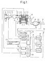
- Figure 1 is an overall view of an internal combustion engine
- Fig. 2 is a view of a map of a basic fuel injection time
- Fig. 3 is a view of a change of a correction coefficient K
- Fig. 4 is a view of a relationship between the correction coefficient K and an engine load Q/N
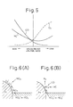
- Fig. 5 is a graph schematically showing a concentration of unburnt HC and CO and oxygen in the exhaust gas discharged from the engine
- Fig. 6 is a view for explaining the absorption and releasing action of NO x
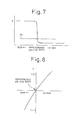
- Fig. 7 is a view showing an output voltage of an air-fuel ratio sensor
- Fig. 8 is a view showing the output voltage V of another air-fuel ratio sensor
- FIG. 9 is a view showing the change of the air-fuel ratio
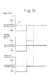
- Fig. 10 is a view showing the change of the air-fuel ratio
- Fig. 11 is a view showing the change of the air-fuel ratio
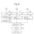
- Fig. 12 and Fig. 13 are flow charts for the control of the air-fuel ratio
- Fig. 14 and Fig. 15 are flow charts of another embodiment for the control of the air-fuel ratio
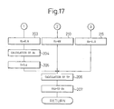
- Fig. 16 and Fig. 17 are flow charts of still another embodiment for performing the air-fuel ratio control
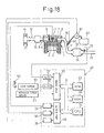
- Fig. 18 is an overall view of a diesel engine
- Fig. 19 is a flow chart for performing the NO x releasing processing
- Fig. 20 is a view of the change of the air-fuel ratio
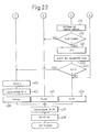
- FIG. 22 are flow charts of a further embodiment for performing the air-fuel ratio control
- Fig. 23 is an overall view of another embodiment of the internal combustion engine
- Fig. 24 is a view of a map of a basic fuel injection time
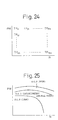
- Fig. 25 is a view of the correction coefficient K
- Fig. 26 is a view of the change of the air-fuel ratio
- Fig. 27 is a view of the change of the air-fuel ratio
- Fig. 28 is a view of the change of the air-fuel ratio
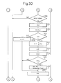
- Fig. 29 to Fig. 31 are flow charts of still another embodiment for performing the air-fuel ratio control
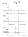
- Fig. 32 is a view of the change of the air-fuel ratio
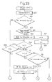
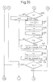
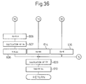
- Fig. 33 to Fig. 36 are flow charts of still another embodiment for performing the air-fuel ratio control.
- Figure 1 shows a case where the present invention is applied to a gasoline engine.
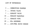
- Fig. 1, 1 denotes an engine body; 2, a piston; 3, a combustion chamber; 4, a spark plug; 5, an intake valve; 6, an intake port; 7, an exhaust valve; and 8, an exhaust port; respectively.
- the intake port 6 is connected via a corresponding branch pipe 9 to a surge tank 10, and fuel injectors 11 for injecting the fuel toward the inside of the intake port 6 are attached to the respective branch pipes 9.
- the surge tank 10 is connected via an intake duct 12 and an air flow meter 13 to an air cleaner 14, and a throttle valve 15 is arranged in the intake duct 12.
- the exhaust port 8 is connected via an exhaust manifold 16 and an exhaust pipe 17 to a casing 19 including an NO x absorber 18.
- An electronic control unit 30 comprises a digital computer and is provided with a ROM (read only memory) 32, RAM (random access memory) 33, a CPU (microprocessor) 34, an input port 35, and an output port 36 which are mutually connected by a bidirectional bus 31.
- the air flow meter 13 generates an output voltage proportional to the intake air amount, and this output voltage is input via a corresponding AD converter 37 to the input port 35.
- a water temperature sensor 20 which generates an output voltage proportional to the engine coolant temperature is attached to the engine body 1, and the output voltage of this water temperature sensor 20 is input via a corresponding AD converter 37 to an input port 35.
- An air-fuel ratio sensor 22 is arranged in the exhaust pipe 21 downstream of the casing 19, and the output voltage or output current of this air-fuel ratio sensor 22 is input via a corresponding AD converter 37 to the input port 35. Also, a rotation speed sensor 23 generating an output pulse expressing the engine rotation speed is connected to the input port 35. On the other hand, the output port 36 is connected via a corresponding drive circuit 38 to the spark plug 4 and the fuel injector 11, respectively.
- TP indicates the basic fuel injection time
- K indicates the correction coefficient.
- the basic fuel injection time TP indicates a fuel injection time necessary for bringing the air-fuel ratio of the air-fuel mixture fed into the engine cylinder to the stoichiometric air-fuel ratio.
- This basic fuel injection time TP is found in advance by experiments and is stored in advance in the ROM 32 in the form of a map as shown in Fig. 2 as a function of the engine load Q/N (intake air amount Q/engine rotation speed N) and the engine rotation speed N.
- the correction coefficient K is a coefficient for controlling the air-fuel ratio of the air-fuel mixture fed into the engine cylinder.
- the air-fuel mixture fed into the engine cylinder comes to have the stoichiometric air-fuel ratio. Contrary to this, when K becomes smaller than 1.0, the air-fuel ratio of the air-fuel mixture fed into the engine cylinder becomes larger than the stoichiometric air-fuel ratio, that is, becomes lean, while when K becomes larger than 1.0, the air-fuel ratio of the air-fuel mixture fed into the engine cylinder becomes smaller than the stoichiometric air-fuel ratio, that is, becomes rich.
- This correction coefficient K is controlled in accordance with the operation state of the engine.
- Figure 3 and Fig. 4 show one embodiment of control of the correction coefficient K.
- an abscissa of Fig. 3 indicates a time and an abscissa of Fig. 4 indicates the load Q/N.
- the correction coefficient K is gradually lowered as the engine coolant temperature becomes higher, and when the warming up is completed, the correction coefficient K is maintained at a constant value smaller than 1.0, that is, the air-fuel ratio of the air-fuel mixture fed into the engine cylinder is maintained at lean.
- the completion of the warming up as shown in Fig. 3 and Fig.
- the correction coefficient K is made for example 1.0, that is, the air-fuel ratio of the air-fuel mixture fed into the engine cylinder is made the stoichiometric air-fuel ratio, and at the time of the full load operation (Z of Fig. 4), the correction coefficient K is made larger than 1.0, that is, the air-fuel ratio of the air-fuel mixture fed into the engine cylinder is made rich.
- Fig. 3 and Fig. 4 in the embodiment shown in Fig. 3 and Fig.
- the air-fuel ratio of the air-fuel mixture fed into the engine cylinder is maintained at the constant lean air-fuel ratio except at the time of the warm-up operation, the time of the idling operation, the time of the high load operation, the time of the acceleration operation and the time of the full load operation, and accordingly in most of the engine operating regions, a lean air-fuel mixture will be burned.
- Figure 5 schematically shows the concentration of representative components in the exhaust gas discharged from the combustion chamber 3.
- the concentration of the unburnt HC and CO in the exhaust gas discharged from the combustion chamber 3 is increased as the air-fuel ratio of the air-fuel mixture fed into the combustion chamber 3 becomes richer, while the concentration of the oxygen O 2 in the exhaust gas discharged from the combustion chamber 3 is increased as the air-fuel ratio of the air-fuel mixture fed into the combustion chamber 3 becomes leaner.
- the NO x absorber 18 accommodated in the casing 19 uses for example alumina as the carrier.
- alumina on this carrier, at least one element selected from alkali metals, for example, potassium K, sodium Na, lithium Li, and cesium Cs, alkali earths such as barium Ba and calcium Ca, rare earths such as lanthanum La and yttrium Y and a precious metal such as platinum Pt are carried.
- this NO x absorber 18 When calling the ratio between the air and fuel (hydrocarbon) fed into the engine intake passage and the exhaust passage upstream of the NO x absorber 18 the air-fuel ratio of the inflowing exhaust gas to the NO x absorber 18, this NO x absorber 18 performs the NO x absorption and releasing action of absorbing the NO x when the air-fuel ratio of the inflowing exhaust gas is lean, while releasing the absorbed NO x when the oxygen concentration in the inflowing exhaust gas is lowered.
- the air-fuel ratio of the inflowing exhaust gas coincides with the air-fuel ratio of the air-fuel mixture fed into the combustion chamber 3, and accordingly, in this case, the NO x absorber 18 will absorb the NO x when the air-fuel ratio of the air-fuel mixture fed into the combustion chamber 3 is lean, while release the absorbed NO x when the oxygen concentration in the air-fuel mixture fed into the combustion chamber 3 is lowered.
- this NO x absorber 18 When the above-mentioned NO x absorber 18 is arranged in the engine exhaust passage, this NO x absorber 18 actually performs the NO x absorption and releasing action, but there also exists some unclarity in the detailed mechanism of this absorption and releasing function. However, this absorption and releasing function is considered to be carried out by the mechanism as shown in Fig. 6. Next, this mechanism will be explained taking as an example a case where platinum Pt and barium Ba are carried on the carrier, but the same mechanism is realized even if other precious metals, alkali metals, alkali earths or rare earths are used.
- the NO 2 is produced on the surface of the platinum Pt, and so far as the NO x absorption capability of the absorber is not saturated, the NO 2 is absorbed into the absorber, and the nitric acid ions NO 3 - are produced. Contrary to this, when the oxygen concentration in the inflowing exhaust gas is lowered and the amount of production of NO 2 is lowered, the reaction is advanced in a reverse direction (NO 3 - ⁇ NO 2 ), thus the nitric acid ions NO 3 - in the absorber are released in the form of NO 2 from the absorber.
- the degree of leanness of the inflowing exhaust gas becomes low, the oxygen concentration in the inflowing exhaust gas is lowered, and accordingly when the degree of leanness of the inflowing exhaust gas is lowered, even if the air-fuel ratio of the inflowing exhaust gas is lean, the NO x will be released from the NO x absorber 18.
- the NO x absorber 18 has a function of a reduction catalyst, and therefore even if the air-fuel ratio of the inflowing exhaust gas is made the stoichiometric air-fuel ratio, the NO x released from the NO x absorber 18 is reduced.
- the air-fuel ratio of the inflowing exhaust gas is made the stoichiometric air-fuel ratio
- the NO x is only gradually released from the NO x absorber 18, and therefore a slightly long time is required for releasing all NO x absorbed in the NO x absorber 18.
- the degree of leanness of the air-fuel ratio of the inflowing exhaust gas is made low as mentioned before, even if the air-fuel ratio of the inflowing exhaust gas is lean, the NO x is released from the NO x absorber 18. Accordingly, so as to release the NO x from the NO x absorber 18, it is sufficient if the oxygen concentration in the inflowing exhaust gas is lowered.
- the air-fuel ratio of the inflowing exhaust gas is made the stoichiometric air-fuel ratio or rich, whereby the NO x released from the NO x absorber 18 is reduced in the NO x absorber 18.
- the air-fuel ratio of the air-fuel mixture fed into the combustion chamber 3 is made rich, while at the time of an idling operation, the time of a high load operation and the time of an acceleration operation, the air-fuel ratio of the air-fuel mixture is made the stoichiometric air-fuel ratio, and therefore this means that the NO x is released from the NO x absorber 18 at the time of the full load operation, the time of the idling operation, the time of the high load operation and the time of the acceleration operation.
- the air-fuel ratio of the inflowing exhaust gas is temporarily made the stoichiometric air-fuel ratio or rich to make the NO x absorber 18 release the NO x .
- the air-fuel ratio of inflowing exhaust gas must be returned to lean when the releasing action of NO x from the NO x absorber 18 is completed, and this means that the completion of the NO x releasing action from the NO x absorber 18 must be detected for this purpose.
- it is detected from the air-fuel ratio detected by the air-fuel ratio sensor 22 when the NO x releasing action from the NO x absorber 18 is completed. An explanation will be made below of this.
- the unburnt HC and CO contained in the exhaust gas are used for reducing the released NO x , and therefore during a time when the NO x is released from the NO x absorber 18, the unburnt HC and CO will never be discharged from the NO x absorber 18. Accordingly, during a time when the NO x is continuously released from the NO x absorber 18, the oxygen O 2 is contained in the exhaust gas discharged from the NO x absorber 18, but no unburnt HC and CO is contained, and accordingly during this term, the air-fuel ratio of the exhaust gas discharged from the NO x absorber 18 has become slightly lean.
- the air-fuel ratio of the exhaust gas discharged from the NO x absorber 18 also becomes the stoichiometric air-fuel ratio, and at this time, where the air-fuel ratio of the air-fuel mixture fed into the combustion chamber 3 is rich, the air-fuel ratio of the exhaust gas discharged from the NO x absorber 18 also becomes rich.
- the air-fuel ratio of the air-fuel mixture discharged from the NO x 18 changes from lean to the stoichiometric air-fuel ratio or rich, and at this time, if the air-fuel ratio of the air-fuel mixture fed into the combustion chamber 3 is made lean, the NO x and unburnt HC and CO will not be discharged into the atmosphere.
- the change of the air-fuel ratio of the exhaust gas discharged from the NO x absorber 18 from lean to the stoichiometric air-fuel ratio or rich is detected by the air-fuel ratio sensor 22, and when the air-fuel ratio detected by the air-fuel ratio sensor 22 is changed from lean to the stoichiometric air-fuel ratio or rich, the air-fuel ratio of the air-fuel mixture fed into the combustion chamber 3 is returned to lean.
- the air-fuel ratio sensor 22 shown in Fig. 1 comprises a cup shaped cylindrical body made of zirconia arranged in the exhaust passage. An anode made of a thin platinum layer is formed on an inner surface of this cylindrical body, and a cathode made of a thin platinum layer is formed on an outer surface of this cylindrical body, respectively. The anode formed on the inner surface of this cylindrical body is exposed to the atmosphere, and the cathode formed on the outer surface of this cylindrical body is exposed to the exhaust gas. Then, when there are no longer any oxygen molecules on the cathode, the oxygen ions move in the zirconia from the anode toward the cathode, and as a result of this, an induced electric power is produced between the anode and the cathode.
- the output voltage of this air-fuel ratio sensor 22 becomes a low voltage of about 0.1(V) when the air-fuel ratio of the exhaust gas is lean, while becomes a high voltage of about 0.9(V) when the air-fuel ratio of the exhaust gas is rich.
- the output voltage of the air-fuel ratio sensor 22 becomes a low voltage of about 0.1(V).
- the air-fuel ratio of the exhaust gas flowing into the NO x absorber 18 is made rich so as to release the NO x from the NO x absorber 18, no unburnt HC and CO at all are contained in the exhaust gas discharged from the NO x absorber 18 as mentioned before during a time when the NO x is released from the NO x absorber 18, and a slight amount of oxygen is contained. Accordingly, also at this time, the oxygen molecules exist on the cathode of the air-fuel ratio sensor 22, and thus the output voltage of the air-fuel ratio sensor 22 becomes a low voltage of about 0.1(V).
- the air-fuel ratio of the exhaust gas discharged from the NO x absorber 18 will contain a large amount of unburnt HC and CO.
- the oxygen molecules on the cathode of the air-fuel ratio sensor 22 are used for oxidizing these unburnt HC and CO, and as a result, the oxygen molecules no longer exist on the cathode, and therefore the output voltage of the air-fuel ratio sensor 22 rapidly rises to about 0.9(V). Accordingly, when the rising of the output voltage V of the air-fuel ratio sensor 22 is detected, it can be detected when the releasing action of NO x is completed by the NO x absorber 18.
- the constant value V 0 is preferably as low as possible within a range where an erroneous decision is not carried out, and in an example shown in Fig. 7, the constant value V 0 is set to 0.3(V).
- the amount of rise of the output voltage V of the air-fuel ratio sensor 22 in this case is smaller than that in a case where the air-fuel ratio of the exhaust gas is made rich, and accordingly in a case where the air-fuel ratio of the exhaust gas is made rich, the completion of the releasing action of NO x can be more reliably detected than a case where the air-fuel ratio of the exhaust gas is made the stoichiometric air-fuel ratio.
- an air-fuel ratio sensor shown in Fig. 8, generating the output voltage V in accordance with the air-fuel ratio as the air-fuel ratio sensor 22.
- an anode and cathode each made of a thin platinum layer are formed on an inner surface and an outer surface of a cap-like cylindrical body made of zirconia, but in this air-fuel ratio sensor, the cathode is covered by a porous layer, and a constant voltage is applied between the cathode and anode.
- a current in accordance with the air-fuel ratio flows between the anode and cathode, and this current is converted to a voltage to generate an output voltage as shown in Fig. 8.
- this air-fuel ratio sensor in a case where this air-fuel ratio sensor is used, it can be detected when the releasing action of NO x is completed by a fact that the output voltage V of the air-fuel ratio sensor becomes zero or negative.
- the amount of change of the output value V when the air-fuel ratio changes from lean to the stoichiometric air-fuel ratio or slightly rich is smaller than that of the case shown in Fig. 7, and accordingly in a case using the air-fuel ratio sensor having characteristics shown in Fig. 7, the completion of the releasing action of NO x can be more easily detected.
- a target value K indicates a correction coefficient value for bringing the air-fuel ratio of the air-fuel mixture fed into the combustion chamber 3 to the target air-fuel ratio determined according to the operation state of the engine
- the control air-fuel ratio indicates the air-fuel ratio of the inflowing exhaust gas to the NO x absorber 18
- the detection air-fuel ratio indicates the air-fuel ratio detected by the air-fuel ratio sensor 22.
- the solid line of Fig. 9 indicates a case where the air-fuel ratio of air-fuel mixture is temporarily made rich so as to release the NO x during the time the lean air-fuel mixture is burned.
- the target value K is maintained at a value smaller than 1.0, that is, the air-fuel ratio of the air-fuel mixture fed into the combustion chamber 3 is maintained lean, and when the NO x should be released, the control air-fuel ratio, that is, in this case, the air-fuel ratio of the air-fuel mixture fed into the combustion chamber 3, is switched to rich.
- the detection air-fuel ratio detected by the air-fuel ratio sensor 22 is maintained slightly leaner than the stoichiometric air-fuel ratio, and when the releasing action of NO x is completed, the detection air-fuel ratio becomes rich.
- the control air-fuel ratio is immediately returned to lean.
- Figure 10 shows a case where the target value K is changed from a value smaller than 1.0 to 1.0, that is, where the operation state of the engine is changed from an operation state where a lean air-fuel mixture should be burned to an operation state where an air-fuel mixture having the stoichiometric air-fuel ratio should be burned.
- the control air-fuel ratio that is, in this case, the air-fuel ratio of the air-fuel mixture fed into the combustion chamber 3 is switched to rich.
- the detection air-fuel ratio detected by the air-fuel ratio sensor 22 is maintained slightly leaner than the stoichiometric air-fuel ratio, and when the releasing action of NO x is completed, the detection air-fuel ratio becomes rich.
- the control air-fuel ratio is immediately switched from rich to the stoichiometric air-fuel ratio.
- Figure 11 shows a case where the target value K is changed from a value smaller than 1.0 to 1.0, that is, where the operation state of the engine is changed from an operation state where a lean air-fuel mixture should be burned to an operation state where a rich air-fuel mixture should be burned.
- the control air-fuel ratio that is, in this case, also the air-fuel ratio of the air-fuel mixture fed into the combustion chamber 3, is switched to rich.
- the detection air-fuel ratio detected by the air-fuel ratio sensor 22 is maintained slightly leaner than the stoichiometric air-fuel ratio, and when the releasing action of NO x is completed, the detection air-fuel ratio becomes rich.
- the control air-fuel ratio that is, the air-fuel ratio of the air-fuel mixture fed into the combustion chamber 3, is continuously maintained at rich.
- Figure 12 and Fig. 13 show the control routine of the correction coefficient K and air-fuel ratio, indicated by the solid line in Fig. 9 to Fig. 11.
- the correction coefficient K is calculated from the operation state of the engine. Subsequently, at step 101, it is determined whether or not the correction coefficient K is smaller than 1.0, that is, whether or not the operation state is a state where a lean air-fuel mixture should be burned.
- K ⁇ 1.0 that is, when the operation state is that a lean air-fuel mixture should be burned
- the processing routine goes to step 102, at which it is determined whether or not the cumulative time T for which the combustion of lean air-fuel mixture is carried out exceeds the predetermined constant time T 0 .
- T ⁇ T 0 the processing routine goes to step 103, at which an NO x releasing flag indicating that the air-fuel ratio is made rich for the releasing of NO x is reset.
- the correction coefficient K t is made for example 0.6.
- the elapsed time ⁇ t from when the processing routine goes to step 105 in the preceding processing cycle is calculated, and then at step 106, ⁇ t is added to the cumulative time T. Accordingly, as mentioned above, this cumulative time indicates a time for which the lean air-fuel mixture is burned.
- a basic fuel injection time TP is calculated from a map shown in Fig. 2, and then at step 108, a fuel injection time TAU is calculated by multiplying the basic fuel injection time TP by the correction coefficient K t . At this time, a lean air-fuel mixture is burned in the combustion chamber 3.
- step 109 the processing routine goes from step 102 to step 109, at which it is decided whether or not the correction coefficient K t is smaller than 1.0.
- K x ⁇ 1.0 the processing routine goes to step 110, at which the correction coefficient K t is made the predetermined value KK.
- This value KK is a value of from 1.1 to 1.2 with which the air-fuel ratio of the air-fuel mixture fed into the combustion chamber 3 becomes about 12.0 to 13.5.
- the air-fuel ratio of the air-fuel mixture fed into the combustion chamber 3 becomes rich. Namely, when the cumulative time T exceeds the constant time T 0 , as indicated by the solid line in Fig. 9, the control air-fuel ratio is switched from lean to rich.
- step 112 At which it is decided whether or not the NO x releasing flag has been set.
- the NO x releasing flag has been set, and therefore the processing routine goes to step 113.
- step 113 the output signal of the air-fuel ratio sensor 22 is read in, and subsequently at step 114, for example it is determined whether or not the output voltage V of the air-fuel ratio sensor 22 exceeds the constant value V 0 shown in Fig.
- step 114 when the air-fuel ratio sensor 22 generates a rich signal, the processing routine goes from step 114 to step 115, at which the cumulative time T is made zero. Subsequently, at step 116, it is determined whether or not the correction coefficient K is smaller than 1.0. At this time, K ⁇ 1.0, and therefore the processing routine goes to step 104, at which the air-fuel ratio of the air-fuel mixture fed into the combustion chamber 3 is switched from rich to lean. In the next processing cycle, it is decided that T ⁇ T 0 at step 102, and therefore the processing routine passes step 103 and goes to step 104, and thus the air-fuel ratio of the air-fuel mixture fed into the combustion chamber 3 is maintained at lean.
- the processing routine goes from step 101 to step 109.
- K t is still smaller than 1.0, and therefore the processing routine goes via steps 110, 111 and 107 to step 108, and thus the air-fuel ratio of the air-fuel mixture fed into the combustion chamber 3 is switched from lean to rich.
- the processing routine passes step 109 to steps 112 and 113 and goes to step 114, at which it is determined whether or not the air-fuel ratio sensor 22 generates a rich signal.
- the processing routine jumps to step 110, and thus, as indicated by the solid line in Fig. 10, the control air-fuel ratio is maintained at rich.
- the processing routine passes step 115 and goes to step 116.
- K 1.0, and therefore the processing routine goes to step 117, at which it is determined whether or not the correction coefficient K is larger than 1.0.
- step 117 it is decided that K ⁇ 1.0, and therefore the processing routine goes to step 118, at which the correction coefficient K t is made 1.0. Subsequently, at step 119, the NO x releasing flag is reset, and then the processing routine passes step 107 and goes to step 108. Accordingly, when the air-fuel ratio sensor 22 generates a rich signal, as indicated by the solid line in Fig. 10, the control air-fuel ratio becomes the stoichiometric air-fuel ratio. In the next processing cycle, the processing routine jumps from step 112 to step 117, and thus the control air-fuel ratio is maintained at the stoichiometric air-fuel ratio.
- the processing routine goes from step 101 to step 109.
- K t is still smaller than 1.0, and therefore the processing routine goes to step 108 via steps 110, 111 and 107, and thus the air-fuel ratio of the air-fuel mixture fed into the combustion chamber 3 is switched from lean to rich.
- the control air-fuel ratio is switched from lean to rich.
- the processing routine goes from step 109 to step 114 while passing steps 112 and 113, and it is determined whether or not the air-fuel ratio sensor 22 generates the rich signal. Until the air-fuel ratio sensor 22 generates a rich signal, the processing routine jumps to step 110, and thus, as shown in Fig. 11, the control air-fuel ratio is maintained rich. Subsequently, when the air-fuel ratio sensor 22 generates a rich signal, the processing routine passes step 115 and goes to step 116. At this time, K > 1.0, and therefore the processing routine goes to step 117, and then the processing routine goes from step 117 to step 110. Thus, in this case, even after the air-fuel ratio sensor 22 generates a rich signal, the rich air-fuel mixture is continuously fed into the combustion chamber 3.
- Figure 14 and Fig. 15 show another embodiment of the air-fuel ratio control routine.
- the control air-fuel ratio is not temporarily made rich, but as indicated by a broken line in Fig. 10, the control air-fuel ratio is made the stoichiometric air-fuel ratio.
- the correction coefficient K is calculated from the operation state of the engine. Subsequently, at step 201, it is determined whether or not the correction coefficient K is smaller than 1.0, that is, whether it is an operation state where a lean air-fuel mixture should be burned.
- K ⁇ 1.0 that is, when it is an operation state where a lean air-fuel mixture should be burned
- the processing routine goes to step 202, at which it is determined whether or not the cumulative time T for which the combustion of the lean air-fuel mixture is carried out exceeds the predetermined constant time T 0 .
- T ⁇ T 0 the processing routine goes to step 203.
- the correction coefficient K t is made for example 0.6.
- the elapsed time ⁇ t from when the processing routine goes to step 204 in the previous processing cycle is calculated, and then at step 205, ⁇ t is added to the cumulative time T. Accordingly, as mentioned above, this cumulative time indicates a time for which the lean air-fuel mixture is burned.
- the basic fuel injection time TP is calculated from the map shown in Fig. 2, and then at step 207, the fuel injection time TAU is calculated by multiplying the basic fuel injection time TP by the correction coefficient K t . At this time, a lean air-fuel mixture is burned in the combustion chamber 3.
- step 208 the processing routine goes from step 202 to step 208, at which it is determined whether or not the correction coefficient K t is smaller than 1.0.
- K t ⁇ 1.0 and therefore the processing routine goes to step 209, at which it is determined whether or not the correction coefficient K is 1.0.
- K ⁇ 1.0 and therefore the processing routine goes to step 210, at which the correction coefficient K t is made the predetermined value KK.
- This value KK is a value of about 1.1 to 1.2 with which the air-fuel ratio of the air-fuel mixture fed into the combustion chamber 3 becomes about 12.0 to 13.5.
- step 201 it is decided that K ⁇ 1.0, while it is decided at step 202 that T > T 0 , and it is decided at step 208 that K t > 1.0, and therefore the processing routine goes to step 211.
- step 211 the output signal of the air-fuel ratio sensor 22 is read in, and then at step 212, it is determined whether or not for example the output value V of the air-fuel ratio sensor 22 exceeds the constant value V 0 shown in Fig. 7, that is, whether or not the air-fuel ratio sensor 22 generates a rich signal indicating that the air-fuel ratio is rich.
- the processing routine jumps from step 212 to step 209, and at this time, K ⁇ 1.0, and therefore the processing routine goes to step 210. Accordingly, during this time, the rich air-fuel mixture is continuously fed into the combustion chamber 3.
- step 212 when the air-fuel ratio sensor 22 generates a rich signal, the processing routine goes from step 212 to step 213, at which the cumulative time T is made zero. Subsequently, at step 214, it is determined whether or not the correction coefficient K is smaller than 1.0. At this time, K ⁇ 1.0, and therefore the processing routine goes to step 203, at which the air-fuel ratio of the air-fuel mixture fed into the combustion chamber 3 is switched from rich to lean. In the next processing cycle, it is decided that T ⁇ T 0 at step 202, and therefore the processing routine goes to step 203, and thus the air-fuel ratio of the air-fuel mixture fed into the combustion chamber 3 is maintained at lean.
- the processing routine goes from step 201 to step 208.
- K t is still smaller than 1.0, and therefore the processing routine goes to step 209.
- it is decided that K 1.0, and therefore the processing routine goes to step 215, at which the correction coefficient K t is made 1.0.
- the processing routine passes step 206 and goes to step 207, and thus the air-fuel ratio of the air-fuel mixture fed into the combustion chamber 3 is switched from lean to the stoichiometric air-fuel ratio.
- the control air-fuel ratio is switched from lean to the stoichiometric air-fuel ratio.
- the processing routine passes step 208 to step 211 and goes to step 212, at which it is determined whether or not the air-fuel ratio sensor 22 generates a rich signal.
- the processing routine passes step 209 and goes to step 215, and thus, as indicated by the broken line in Fig. 10, the control air-fuel ratio is maintained at the stoichiometric air-fuel ratio.
- the processing routine passes step 213 and goes to step 214.
- K 1.0, and therefore the processing routine goes to step 209, and then goes to step 215. Accordingly, even after the air-fuel ratio sensor 22 generates a rich signal, the control air-fuel ratio will be maintained at the stoichiometric air-fuel ratio.
- the processing routine goes from step 201 to step 208.
- K t is still smaller than 1.0, and therefore the processing routine goes to step 209.
- the processing routine goes from step 208 to step 212 while passing step 211, and it is determined whether or not the air-fuel ratio sensor 22 generates a rich signal. Until the air-fuel ratio sensor 22 generates a rich signal, the processing routine passes step 209 and goes to step 210, and thus, as shown in Fig. 11, the control air-fuel ratio is maintained at rich. Subsequently, when the air-fuel ratio sensor 22 generates a rich signal, the processing routine passes step 213 and goes to step 214. At this time, K > 1.0, and therefore the processing routine goes to step 209, and then goes to step 210. Thus, even after the air-fuel ratio sensor 22 generates a rich signal, the rich air-fuel mixture is continuously fed into the combustion chamber 3.
- Figure 16 and Fig. 17 show still another embodiment of the air-fuel ratio control routine.
- the control air-fuel ratio is made the stoichiometric air-fuel ratio.
- the cumulative time T exceeds the constant time T 0 when the lean air-fuel mixture is burned, the control air-fuel ratio is not temporarily made rich, but as indicated by the broken line in Fig. 9, the control air-fuel ratio is made the stoichiometric air-fuel ratio.
- step 209a of Fig. 16 it is determined whether or not K ⁇ 1.0
- the processing routine goes to step 215, and when it is determined as K > 1.0. the processing routine goes to step 110.
- the processing routine passes step 208 and goes to step 209a.
- the processing routine goes to step 215, and thus the control air-fuel ratio is switched from lean to the stoichiometric air-fuel ratio.
- the processing routine goes from step 214 to step 203, and the control air-fuel ratio is returned to lean again.
- Figure 18 shows a case where the present invention is applied to the diesel engine. Note that, in Fig. 18, constituent elements the same as those shown in Fig. 1 are indicated by the same references.
- the average air-fuel ratio of the air-fuel mixture in the combustion chamber 3 is made lean and the hydrocarbon is fed into the engine exhaust passage upstream of the NO x absorber 18, whereby the air-fuel ratio of the exhaust gas flowing into the NO x absorber 18 is made rich.
- a load sensor 51 generating an output voltage proportional to the depression of an accelerator pedal 50 is provided, and the output voltage of this load sensor 51 is input via a corresponding AD converter 37 to the input port 35.
- a reduction agent feeding valve 60 is arranged in an exhaust pipe 17, which reduction agent feeding valve 60 is connected via a feeding pump 61 to a reduction agent tank 62.
- the output ports 36 of the electronic control unit 30 are respectively connected via corresponding drive circuits 38 to the reduction agent feeding valve 60 and the feeding pump 61.
- a hydrocarbon such as gasoline, isooctane, hexane, heptane, light oil or lamp oil or a hydrocarbon which can be stored in the liquid state, for example, butane or propane, is filled.
- the air-fuel mixture in the combustion chamber 3 is usually burned under an air excess, that is, in a state where the average air-fuel ratio is lean, and at this time, NO x discharged from the engine is absorbed into the NO x absorber 18.
- the feeding pump 61 is driven and, at the same time, the reduction agent feeding valve 60 is opened, whereby the hydrocarbon filled in the reduction agent tank 62 is fed from the reduction agent feeding valve 60 into the exhaust pipe 17.
- the amount of feeding of the hydrocarbon at this time is determined so that the air-fuel ratio of the exhaust gas flowing into the NO x absorber 18 becomes rich, and accordingly, at this time, the NO x will be released from the NO x absorber 18.
- Figure 19 shows a routine for executing this NO x releasing processing, which routine is executed by interruption at predetermined time intervals.
- step 300 it is determined whether or not the cumulative time T for which the operation of the engine is carried out exceeds the predetermined constant time T 0 .
- the processing routine goes to step 308, at which an interruption time interval ⁇ t is added to the cumulative time T, and then the processing cycle is completed.
- T becomes larger than T 0 the feeding pump 61 is driven at step 301, and then at step 302, the reduction agent feeding valve 60 is opened and the reduction agent is fed into the exhaust pipe 17.
- step 303 the output signal of the air-fuel ratio sensor 22 is read in, and then at step 304, it is determined whether or not for example the output voltage V of the air-fuel ratio sensor 22 exceeds the constant value V 0 shown in Fig. 7, that is, whether or not the air-fuel ratio sensor 22 generates a rich signal indicating that the air-fuel ratio is rich.
- V 0 the constant value shown in Fig. 7
- the NO x is continuously released from the NO x absorber 18, and therefore the detection air-fuel ratio detected by the air-fuel ratio sensor 22 has become slightly lean, and accordingly during this period, after the processing routine jumps from step 304 to step 308, the processing cycle is completed.
- step 304 the processing routine goes from step 304 to step 305, at which the driving of the feeding pump 61 is stopped.
- step 306 the reduction agent feeding valve 60 is closed, and thus the feeding of the reduction agent is stopped.
- step 307 the cumulative time T is made zero.
- the NO x absorber 18 has a nature such that the detection air-fuel ratio is maintained slightly leaner than the stoichiometric air-fuel ratio after the control air-fuel ratio is switched from lean to the stoichiometric air-fuel ratio or rich, and in the embodiments mentioned heretofore, this nature is utilized to detect that the NO x releasing action from the NO x absorber 18 is completed.
- this nature is utilized to detect that the NO x releasing action from the NO x absorber 18 is completed.
- NO x absorber 18 there is a delay in the releasing starting action of NO x from the NO x absorber 18, and accordingly there sometimes occurs a case where NO x is not immediately released from the NO x absorber 18 even when the control air-fuel ratio is switched from lean to rich.
- the correction coefficient K is calculated from the operation state of the engine. Subsequently, at step 401, it is determined whether or not the correction coefficient K is larger than 1.0, that is, whether or not it is the operation state where the rich air-fuel mixture should be burned.
- K ⁇ 1.0 that is, when it is the operation state where the air-fuel mixture of the stoichiometric air-fuel ratio or the lean air-fuel mixture should be burned
- the processing routine goes to step 402, at which it is determined whether or not the correction coefficient is smaller than 1.0, that is, whether or not it is an operation state where the lean air-fuel mixture should be burned.
- the processing routine goes to step 403, at which it is determined whether or not the correction coefficient is smaller than 1.0, that is, whether or not the operation state is a state where the lean air-fuel mixture should be burned.
- the processing routine goes to step 403, at which it is determined whether or not the cumulative time T for which the combustion of lean air-fuel mixture is carried out exceeds the predetermined constant time T 0 .
- T ⁇ T 0 the processing routine goes to step 404.
- the correction coefficient K t is made for example 0.6.
- the elapsed time ⁇ t from when the processing routine goes to step 405 in the previous processing cycle is calculated, and then at step 406, ⁇ t is added to the cumulative time T. Accordingly, as mentioned above, this cumulative time indicates a time for which the lean air-fuel mixture is burned.
- the basic fuel injection time TP is calculated from the map shown in Fig. 2, and then at step 408, the fuel injection time TAU is calculated by multiplying the basic fuel injection time TP by the correction coefficient K t . At this time, a lean air-fuel mixture is burned in the combustion chamber 3.
- step 403 the processing routine goes from step 403 to step 409, at which it is determined whether or not the correction coefficient K t is smaller than 1.0.
- K t ⁇ 1.0, and therefore the processing routine goes to step 410, at which the NO x releasing flag is set, and then the processing routine goes to step 412, at which the inhibition flag is set.
- step 412 the processing routine goes to step 412, at which the correction coefficient K t is made the predetermined KK.
- This value KK is a value of about 1.1 to 1.2 with which the air-fuel ratio of the air-fuel mixture fed into the combustion chamber 3 becomes about 12.0 to 13.5.
- step 402 it is decided that K ⁇ 1.0, while it is decided at step 403 that T > T 0 , and it is decided at step 409 that K t > 1.0, and therefore the processing routine goes to step 413, at which it is determined whether or not the NO x releasing flag has been set. At this time, the NO x releasing flag has been set, and therefore the processing routine goes to step 414. At step 414, it is determined whether or not the inhibition flag has been set. At this time, the inhibition flag has been set, and therefore the processing routine goes to step 415, at which the count value CC is incremented by "1".
- step 416 it is determined whether or not the count value becomes larger than the predetermined constant period CC 0 shown in Fig. 20.
- CC ⁇ CC 0 that is, when the constant period CC 0 is not elapsed after the control air-fuel ratio is switched from lean to rich
- the processing routine goes to step 412, and accordingly a rich air-fuel mixture is continuously fed into the combustion chamber 3.
- step 416 when CC becomes equal to or larger than CC 0 , that is, when the constant period CC 0 is elapsed from when the control air-fuel ratio is switched from lean to rich, the processing routine goes from step 416 to step 417, at which the inhibition flag is reset. Subsequently, at step 418, the count value CC is made zero, and then the processing routine goes to step 419. Note that, when the inhibition flag is reset, in the subsequent processing cycles, the processing routine jumps from step 414 to step 419.
- the output signal of the air-fuel ratio sensor 22 is read in, and then at step 420, it is determined whether or not for example the output voltage V of the air-fuel ratio sensor 22 exceeds the constant value V 0 shown in Fig. 7, that is, whether or not the air-fuel ratio sensor 22 generates a rich signal indicating that the air-fuel ratio is rich.
- the processing routine jumps from step 420 to step 412, and thus the rich air-fuel mixture is continuously fed into the combustion chamber 3.
- step 423 it is determined whether or not the correction coefficient K is smaller than 1.0.
- K ⁇ 1.0 and therefore the processing routine goes to step 404, at which the air-fuel ratio of the air-fuel mixture fed into the combustion chamber 3 is switched from rich to lean.
- step 403 it is decided that T ⁇ T 0 , and therefore the processing routine goes to step 404, and thus the air-fuel ratio of the air-fuel mixture fed into the combustion chamber 3 is maintained lean.
- the processing routine passes step 401 and goes from step 402 to step 409.
- K t is still smaller than 1.0, and therefore the processing routine goes to step 408 via steps 410, 411, 412 and 407, and thus the air-fuel ratio of the air-fuel mixture fed into the combustion chamber 3 is switched from lean to rich.
- the control air-fuel ratio is switched from lean to rich.
- the processing routine passes step 409 to steps 413, 414 and 415 and goes to step 416, at which it is determined whether or not the count value CC becomes larger than the constant period CC 0 shown in Fig. 20.
- the processing routine goes to step 412, and accordingly the control air-fuel ratio is maintained rich.
- the processing routine goes to step 419 while passing steps 417 and 418, at which it is determined whether or not the air-fuel ratio sensor 22 generates a rich signal.
- the processing routine goes from step 401 to step 425, at which the cumulative time T is made zero, and then the processing routine goes to step 424, at which K t is made K (> 1.0). Subsequently, the processing routine passes step 407 and goes to step 408, and thus the air-fuel ratio of the air-fuel mixture fed into the combustion chamber 3 is switched from lean to rich. Namely, when the operation state of the engine is shifted from the operation state where a lean air-fuel mixture should be burned to the full load operation state, the control air-fuel ratio is switched from lean to rich.
- FIG. 23 shows a further embodiment. Note that, in this embodiment, similar constituent elements to those in Fig. 1 are indicated by same references.
- a pressure sensor 24 generating an output voltage proportional to an absolute pressure in the surge tank 10 is attached to the inside the surge tank 10, and the output voltage of this pressure sensor 24 is input via the corresponding AD converter 37 to the input port 35.
- the basic fuel injection time TP is preliminarily found by an experiment, and this basic fuel injection time TP is preliminarily stored in the form of a map as shown in Fig. 24 in the ROM 32 as the function of the engine rotational speed N and the absolute pressure PM of the surge tank 10 expressing the engine load.
- the value of the correction coefficient K is predetermined with respect to the absolute pressure PM in the surge tank 10 and the engine rotational speed N
- Fig. 25 shows one example of the value of this correction coefficient K.
- the value of the correction coefficient K in an area where the absolute pressure PM in the surge tank 10 is relatively low, that is, in the engine low and middle load operation areas, the value of the correction coefficient K is made a value smaller than 1.0, and accordingly at this time, the air-fuel ratio of the air-fuel mixture fed into the engine cylinder is made lean.
- the value of the correction coefficient K is made 1.0, and accordingly at this time, the air-fuel ratio of the air-fuel mixture fed into the engine cylinder is made the stoichiometric air-fuel ratio. Also, in an area where the absolute pressure PM in the surge tank 10 becomes the highest, that is, in an engine full load operation area, the value of the correction coefficient K is made a value larger than 1.0, and accordingly at this time, the air-fuel ratio of the air-fuel mixture fed into the engine cylinder is made rich.
- control air-fuel ratio is controlled, but a fundamental aim of this embodiment is to detect which degree of amount of NO x is absorbed in the NO x absorber 18 during a period when the lean air-fuel mixture is burned unlike the embodiments mentioned heretofore. Namely, as mentioned before, when the releasing action of NO x from the NO x absorber 18 is completed, the air-fuel ratio of the exhaust gas discharged from the NO x absorber 18 is changed from lean to rich.
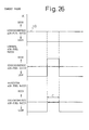
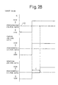
- Figure 26 to Fig. 28 show the NO x releasing control and the air-fuel ratio control of the air-fuel mixture fed into the combustion chamber 3.
- the method of detection of the amount of NO x absorbed in the NO x absorber 18 will be explained while explaining these controls.
- the solid line of Fig. 26 indicates a case where the air-fuel ratio of air-fuel mixture is temporarily made rich so as to release NO x during the combustion of the lean air-fuel mixture.
- the target value K is maintained at a value smaller than 1.0, that is, the air-fuel ratio of the air-fuel mixture fed into the combustion chamber 3 is maintained lean, and when NO x should be released, the control air-fuel ratio, that is, in this case, the air-fuel ratio of the air-fuel mixture fed into the combustion chamber 3, is switched to rich.
- the detection air-fuel ratio detected by the air-fuel ratio sensor 22 is maintained slightly leaner than the stoichiometric air-fuel ratio, and when the releasing action of NO x is completed, the detection air-fuel ratio becomes rich.
- an elapsed time indicated by C in Fig. 26 expresses the amount of NO x absorbed in the NO x absorber 18. Note that, as shown in Fig. 26, when the detection air-fuel ratio becomes rich, the control air-fuel ratio is immediately returned to lean.
- Figure 27 shows a case where the target value K is changed from a value smaller than 1.0 to 1.0, that is a case where the operation state of engine is changed from the operation state where a lean air-fuel mixture should be burned to the operation state where an air-fuel mixture having the stoichiometric air-fuel ratio should be burned.
- the control air-fuel ratio that is, in this case, the air-fuel ratio of the air-fuel mixture fed into the combustion chamber 3 is switched to rich.
- the detection air-fuel ratio detected by the air-fuel ratio sensor 22 is maintained slightly leaner than the stoichiometric air-fuel ratio, and when the releasing action of NO x is completed, the detection air-fuel ratio becomes rich.
- an elapsed time indicated by C in Fig. 26 expresses the amount of NO x absorbed in the NO x absorber 18. Note that, in this case, when the detection air-fuel ratio becomes rich, the control air-fuel ratio is immediately switched from rich to the stoichiometric air-fuel ratio.
- Figure 28 shows a case where the target value K is changed from a value smaller than 1.0 to a value larger than 1.0, that is, a case where the operation state of engine is changed from the operation state where a lean air-fuel mixture should be burned to the operation state where a rich air-fuel mixture should be burned.
- the control air-fuel ratio that is, in this case, the air-fuel ratio of the air-fuel mixture fed into the combustion chamber 3, is switched to rich.
- the detection air-fuel ratio detected by the air-fuel ratio sensor 22 is maintained slightly leaner than the stoichiometric air-fuel ratio, and when the releasing action of NO x is completed, the detection air-fuel ratio becomes rich.
- an elapsed time indicated by C in Fig. 28 expresses the amount of NO x absorbed in the NO x absorber 18. Note that, in this case, even though the detection air-fuel ratio becomes rich, the control air-fuel ratio, that is the air-fuel ratio of the air-fuel mixture fed into the combustion chamber 3, is continuously made rich.
- the amount of NO x absorbed in the NO x absorber 18 can be detected.
- the amount of NO x absorbed in the NO x absorber 18 is detected from the elapsed time C from when the air-fuel ratio of the air-fuel mixture fed into the combustion chamber 3 is switched from lean to rich to when the air-fuel ratio detected by the air-fuel ratio sensor 22 is changed from lean to rich, but so as to detect the amount of NO x absorbed in the NO x absorber 18 more correctly, preferably the calculation of the elapsed time C is started when the air-fuel ratio of the exhaust gas flowing into the NO x absorber 18 is changed from lean to rich.
- the amount of NO x absorbed in the NO x absorber 18 can be detected. For example, when the SO x or CO 2 contained in the exhaust gas is absorbed into the NO x absorber 18, and as a result the amount of NO x absorbed in the NO x absorber 18 is reduced, it becomes possible to decide that deterioration has occurred in the NO x absorber 18.
- a main cause of deterioration of the NO x absorber 18 resides in the absorption of SO x into the NO x absorber 18, and accordingly this means that, when the amount of absorption of SO x into the NO x absorber 18 is increased, the SO x must be released from the NO x absorber 18 so as to increase the absorption capacity of NO x .
- the amount of absorption of SO x into the NO x absorber 18 is increased, the amount of absorption of NO x is decreased, and therefore this means that, if the amount of absorption of NO x can be detected, the amount of absorption of SO x can be roughly estimated. Therefore, in this embodiment, the amount of absorption of SO x is estimated from the amount of absorption of NO x , and when the amount of absorption of SO x exceeds the predetermined limit, the SO x is released from the NO x absorber 18.
- this sulfate BaSO 4 is difficult to decompose, and even if the air-fuel ratio of the inflowing exhaust gas is made rich for a short time, only a small amount of SO x is released from the NO x absorber 18. Accordingly, as the time is elapsed, the sulfate BaSO 4 is increased in the NO x absorber 18, and thus as time elapses, the amount of NO x that can be absorbed by the NO x absorber 18 will be lowered.
- the SO x is released from the NO x absorber 18, and accordingly in this embodiment, when the SO x should be released, the air-fuel ratio of the air-fuel mixture fed into the combustion chamber 3 is made the stoichiometric air-fuel ratio or rich for about 10 minutes.
- the temperature of the NO x absorber 18 is higher, the SO x becomes be more easily released, and therefore when the SO x should be released, preferably the NO x absorber 18 or the exhaust gas flowing into the NO x absorber 18 is heated by an electric heater, etc.
- the air-fuel ratio of the air-fuel mixture fed into the combustion chamber 3 must be maintained at the stoichiometric air-fuel ratio or rich for a long time, and accordingly so as to attempt the reduction of the fuel consumption rate, preferably the frequency of bringing the air-fuel ratio of air-fuel mixture to the stoichiometric air-fuel ratio or rich is reduced as much as possible. Accordingly, in this embodiment, the amount of NO x absorbed in the NO x absorber 18 is detected and the releasing action of SO x is only carried out in a case where this NO x amount becomes the set amount or lesst.
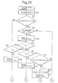
- Figure 29 to Fig. 31 show the control routine of the air-fuel ratio, which routine is executed by interruption at predetermined time intervals.
- the correction coefficient K is calculated from Fig. 25 based on the operation state of the engine. Subsequently, at step 501, it is determined whether or not the SO x releasing flag indicating that the SO x should be released has been set. When the SO x releasing flag has not been set, the processing routine jumps to step 504, at which it is determined whether or not the correction coefficient K is smaller than 1.0, that is, whether or not it is an operation state where the lean air-fuel mixture should be burned.
- step 505 When K ⁇ 1.0, that is, when it is an operation state where the lean air-fuel mixture should be burned, the processing routine goes to step 505, at which it is determined whether or not the cumulative time T for which the combustion of the lean air-fuel mixture is carried out exceeds the predetermined constant time T 0 .
- T ⁇ T 0 the processing routine goes to step 506, at which the NO x releasing flag indicating that the air-fuel ratio has been made rich for releasing the NO x is reset.
- the correction coefficient K t is made for example 0.6.
- the elapsed time ⁇ t from when the processing routine goes to step 204 in the previous processing cycle is calculated, and then at step 509, ⁇ t is added to the cumulative time T. Accordingly, as mentioned above, this cumulative time indicates a time for which the lean air-fuel mixture is burned.
- the basic fuel injection time TP is calculated from the map shown in Fig. 24, and then at step 511, the fuel injection time TAU is calculated by multiplying the basic fuel injection time TP by the correction coefficient K t . At this time, a lean air-fuel mixture is burned in the combustion chamber 3.
- step 505 the processing routine goes from step 505 to step 512, at which it is determined whether or not the correction coefficient K t is smaller than 1.0.
- K t ⁇ 1.0, and therefore the processing routine goes to step 513, at which the NO x releasing flag is set, and then the processing routine goes to step 514, at which the correction coefficient K t is made the predetermined value KK.
- This value KK is a value of about 1.1 to 1.2 with which the air-fuel ratio of the air-fuel mixture fed into the combustion chamber 3 becomes about 12.0 to 13.5.
- step 504 it is decided that K ⁇ 1.0 at step 504, while it is decided at step 505 that T > T 0 , and it is decided at step 512 that K t > 1.0, and therefore the processing routine goes to step 515, at which it is determined whether or not the NO x releasing flag has been set.
- step 516 the count value C for calculating the elapsed time C (Fig. 26) is incremented by "1".
- the output signal of the air-fuel ratio sensor 22 is read in, and then at step 518, it is determined whether or not for example the output value V of the air-fuel ratio sensor 22 exceeds the constant value V 0 shown in Fig.7, that is, whether or not the air-fuel ratio sensor 22 generates a rich signal indicating that the air-fuel ratio is rich.
- the processing routine jumps from step 518 to step 514, and thus the rich air-fuel mixture is continuously fed into the combustion chamber 3.
- the processing routine goes from step 518 to step 519, at which the cumulative time T is made zero.
- the ⁇ C is calculated by adding C to ⁇ C.
- step 528 it is determined whether or not the correction coefficient K is smaller than 1.0. At this time, K ⁇ 1.0, and therefore the processing routine goes to step 507, at which the air-fuel ratio of the air-fuel mixture fed into the combustion chamber 3 is switched from rich to lean. In the next processing cycle, it is decided at step 505 that T ⁇ T 0 , and therefore the processing routine passes step 506 and goes to step 507, and thus the air-fuel ratio of the air-fuel mixture fed into the combustion chamber 3 is maintained lean.
- step 523 n is made zero, and then at step 524, ⁇ C is made zero.
- step 525 it is determined whether or not the average value of the elapsed time is smaller than C 0 .
- the processing routine goes from step 501 to step 502, at which it is determined whether or not a constant time, for example, 10 minutes, has lapsed. When 10 minutes has not lapsed, the processing routine jumps to step 530, at which it is determined whether or not the correction coefficient K is larger than 1.0.
- K > 1.0 the processing routine passes step 514 and goes to step 510, and thus at this time, a rich air-fuel mixture is fed into the combustion chamber 3. Contrary to this, when K ⁇ 1.0, the processing routine goes to step 531, at which K t is made equal to 1.0, and then after the NO x releasing flag is reset at step 532, the processing routine goes to step 510.
- the processing routine goes from step 502 to step 503, at which the SO x releasing flag is reset, and then the processing routine goes to step 504.
- the processing routine goes from step 504 to step 512.
- K t is still smaller than 1.0, and therefore the processing routine goes to step 511 via steps 513, 514 and 510, and thus the air-fuel ratio of the air-fuel mixture fed into the combustion chamber 3 is switched from lean to rich.
- the control air-fuel ratio is switched from lean to rich.
- the processing routine passes step 512 to steps 515, 516 and 517 and goes to step 518, at which it is determined whether or not the air-fuel ratio sensor 22 generates a rich signal. Until the air-fuel ratio sensor 22 generates a rich signal, the processing routine jumps to step 514, and thus, as indicated by the solid line in Fig. 27, the control air-fuel ratio is maintained at rich. Subsequently, when the air-fuel ratio sensor 22 generates a rich signal, the processing routine passes step 519 to 521, 529 and step 527 or passes step 519 to step 527, and goes to step 528.
- the processing routine goes from step 504 to step 512.
- K t is still smaller than 1.0, and therefore the processing routine goes to step 511 via steps 513, 514 and 510, and thus the air-fuel ratio of the air-fuel mixture fed into the combustion chamber 3 is switched from lean to rich.
- the control air-fuel ratio is switched from lean to rich.
- the amount of NO x absorbed in the NO x absorber 18 can be correctly detected. Also, the degree of deterioration of the NO x absorber 18 can be estimated from this NO x amount, and when the degree of deterioration of the NO x absorber 18 is advanced, the SO x which has become the main cause of deterioration is released from the NO x absorber 18 and thus the toxicity by SO x of the NO x absorber 18 can be solved.
- a decision of whether or not the detection air-fuel ratio becomes rich is inhibited for a constant time CC 0 after the switching of the control air-fuel ratio from rich to lean, and the amount of NO x absorbed in the NO x absorber 18 is detected from the elapsed time C of from when this constant time CC 0 is elapsed to when the detection air-fuel ratio becomes rich.
- the air-fuel ratio of the air-fuel mixture is made rich for for example 10 minutes irrespective of the value of the correction coefficient K.
- the correction coefficient K is calculated from Fig. 25 based on the operation state of the engine. Subsequently, at step 601, it is determined whether or not the SO x releasing flag indicating that the SO x should be released has been set. When the SO x releasing flag has not been set, the processing routine jumps to step 604, at which it is determined whether or not the correction coefficient K is smaller than 1.0, that is, whether or not it is an operation state where the lean air-fuel mixture should be burned.
- step 605 When K ⁇ 1.0, that is, when it is an operation state where the lean air-fuel mixture should be burned, the processing routine goes to step 605, at which it is determined whether or not the cumulative time T for which the combustion of the lean air-fuel mixture is carried out exceeds the predetermined constant time T 0 .
- T ⁇ T 0 the processing routine goes to step 606.
- the correction coefficient K t is made for example 0.6.
- the elapsed time ⁇ t from when the processing routine goes to step 607 in the previous processing cycle is calculated, and then at step 608, ⁇ t is added to the cumulative time T. Accordingly, as mentioned above, this cumulative time indicates a time for which the lean air-fuel mixture is burned.
- the basic fuel injection time TP is calculated from the map shown in Fig. 24, and then at step 610, the fuel injection time TAU is calculated by multiplying the basic fuel injection time TP by the correction coefficient K t . At this time, a lean air-fuel mixture is burned in the combustion chamber 3.
- step 605 the processing routine goes from step 605 to step 611, at which it is determined whether or not the correction coefficient K t is smaller than 1.0.
- K t ⁇ 1.0, and therefore the processing routine goes to step 612, at which the NO x releasing flag is set, and then the processing routine goes to step 613, at which the inhibition flag is set.
- step 614 the processing routine goes to step 614, at which the correction coefficient K t is made the predetermined value KK.
- This value KK is a value of about 1.1 to 1.2 with which the air-fuel ratio of the air-fuel mixture fed into the combustion chamber 3 becomes about 12.0 to 13.5.
- step 604 it is decided that K ⁇ 1.0 at step 604, while it is decided at step 605 that T > T 0 , and it is decided at step 611 that K t > 1.0, and therefore the processing routine goes to step 615, at which it is determined whether or not the NO x releasing flag has been set.
- step 616 it is determined whether or not the inhibition flag has been set.
- the processing routine goes to step 617, at which the count value CC is incremented by "1".
- step 618 it is determined whether or not the count value becomes larger than the predetermined constant period CC 0 shown in Fig. 32.
- CC ⁇ CC 0 that is, when the constant period CC 0 has not elapsed after the control air-fuel ratio is switched from lean to rich
- the processing routine goes to step 614, and accordingly the rich air-fuel mixture is continuously fed into the combustion chamber 3.
- step 618 when CC becomes equal to or larger than CC 0 , that is, when a constant period CC 0 has elapsed from when the control air-fuel ratio is switched from lean to rich, the processing routine goes from step 618 to step 619, at which the inhibition flag is reset. Subsequently, at step 620, the count value CC is made zero, and then the processing routine goes to step 621. Note that, when the inhibition flag is reset, in the subsequent processing cycles, the processing routine jumps from step 616 to step 621.
- the count value C for calculating the elapsed time C (Fig. 32) is incremented by "1".
- the output signal of the air-fuel ratio sensor 22 is read in, and then at step 623, it is determined whether or not for example the output voltage V of the air-fuel ratio sensor 22 exceeds the constant value V 0 shown in Fig. 7, that is, whether or not the air-fuel ratio sensor 22 generates a rich signal indicating that the air-fuel ratio is rich.
- the processing routine jumps from step 623 to step 614, and thus the rich air-fuel mixture is continuously fed into the combustion chamber 3.
- the processing routine goes from step 623 to step 624, and the cumulative time T is made zero.
- the ⁇ C is calculated by adding C to ⁇ C.
- step 634 the NO x releasing flag is reset, and then at step 635, it is determined whether or not the correction coefficient K is smaller than 1.0.
- K ⁇ 1.0 and therefore the processing routine goes to step 606, at which the air-fuel ratio of the air-fuel mixture fed into the combustion chamber 3 is switched from rich to lean.
- step 605 it is decided at step 605 that T ⁇ T 0 , and therefore the processing routine goes to step 606, and thus the air-fuel ratio of the air-fuel mixture fed into the combustion chamber 3 is maintained lean.
- step 628 n is made zero, and then at step 629, ⁇ C is made zero.
- step 630 it is determined whether or not the average value of the elapsed time is smaller than C 0 .
- the processing routine goes from step 601 to step 602, at which it is determined whether or not a constant time, for example 10 minutes, has lapsed.
- a constant time for example 10 minutes
- the processing routine goes to step 637, at which the K t is made the constant value KK (> 1.0), and then at step 638, the cumulative time T is made zero.
- the processing routine passes step 609 and goes to step 610. Accordingly, when the SO x releasing flag is set, for 10 minutes after this, the air-fuel ratio of the air-fuel mixture fed into the combustion chamber 3 is made rich, and thus during this time, all SO x will be released from the NO x absorber 18.
- the processing routine goes from step 602 to step 603, at which the SO x releasing flag is reset, and then the processing routine goes to step 604.
- the processing routine goes from step 604 to step 611.
- K t is still smaller than 1.0, and therefore the processing routine goes to step 610 via steps 612, 613, 614 and 609, and thus the air-fuel ratio of the air-fuel mixture fed into the combustion chamber 3 is switched from lean to rich.
- the control air-fuel ratio is switched from lean to rich.
- the processing routine passes step 611 to steps 615, 616 and 617 and goes to step 618, at which it is determined whether or not the count value CC becomes larger than the constant period CC 0 shown in Fig. 32.
- the processing routine goes to step 614, and accordingly the control air-fuel ratio is maintained rich.
- the processing routine passes steps 619 to 622 and goes to step 623, at which it is determined whether or not the air-fuel ratio sensor 22 generates a rich signal.
- the processing routine goes from step 604 to step 612.
- K t is still smaller than 1.0, and therefore the processing routine goes to step 610 via steps 612, 613, 614 and 609, and thus the air-fuel ratio of the air-fuel mixture fed into the combustion chamber 3 is switched from lean to rich.
- the control air-fuel ratio is switched from lean to rich.
- the processing routine passes step 611 to steps 615, 616 and 617 and goes to step 618, at which it is determined whether or not the count value CC becomes larger than the constant period CC 0 shown in Fig. 32.
- the processing routine goes to step 614, and accordingly the control air-fuel ratio is maintained at rich.
- the processing routine passes steps 619 to 622 and goes to step 623, at which it is determined whether or not the air-fuel ratio sensor 22 generates a rich signal.
- the processing routine goes to step 614, and thus the control air-fuel ratio is maintained at rich. Subsequently, when the air-fuel ratio sensor 22 generates a rich signal, the processing routine passes step 624 to step 634 and goes to step 635. At this time, K > 1.0, and therefore the processing routine goes to step 636, at which K t is made K (> 1.0). Subsequently, the processing routine passes step 609 and goes to step 610. Thus, in this case, even after the air-fuel ratio sensor 22 generates the rich signal, the rich air-fuel mixture is continuously fed into the combustion chamber 3.
Claims (18)
- Dispositif d'épuration de gaz d'échappement d'un moteur à combustion interne dans lequel un absorbeur de NOx, qui absorbe le NOx lorsque le rapport air-carburant d'un gaz d'échappement entrant est pauvre et libère le NOx absorbé lorsque le rapport air-carburant du gaz d'échappement entrant est le rapport air-carburant stoechiométrique ou riche, est disposé dans un passage d'échappement de moteur, un capteur de rapport air-carburant est disposé dans le passage d'échappement de moteur en aval dudit absorbeur du NOx et un moyen de décision de l'achèvement de la libération de NOx est prévu pour décider que l'action de libération du NOx à partir de l'absorbeur de NOx est achevée lorsque le rapport air-carburant détecté par le capteur de rapport air-carburant passe du rapport air-carburant pauvre au rapport air-carburant stoechiométrique ou riche après que le rapport air-carburant du gaz d'échappement circulant dans l'absorbeur NOx soit passé du rapport air-carburant pauvre au rapport air-carburant stoechiométrique ou riche et que l'action de libération du NOx à partir de l'absorbeur de NOx ait commencé.
- Dispositif d'épuration de gaz d'échappement d'un moteur à combustion interne selon la revendication 1, dans lequel le capteur de rapport air-carburant comprend un capteur présentant une sortie qui change brusquement au niveau du rapport air-carburant stoechiométrique.
- Dispositif d'épuration de gaz d'échappement d'un moteur à combustion interne selon la reverdication 1, dans lequel un moyen d'interdiction de décision est prévu pour interdire la décision d'achèvement de l'action de libération du NOx par ledit moyen le décision de l'achèvement de la libération du NOx pendant une durée prédéterminée à partir du moment où le rapport air-carburant du gaz d'échappement circulant dans l'absorbeur de NOx passe du rapport air-carburant pauvre au rapport air-carburant stoechiométrique ou riche.
- Dispositif d'épuration de gaz d'échappement d'un moteur à combustion interne selon la revenclication 1, dans lequel le maintien du rapport air-carburant du gaz d'échappement au niveau du rapport air-carburant stoechiométrique ou riche pour la libération de NOx est stoppé lorsqu'il est décidé par le moyen de décision d'achèvement de la libération du NOx que l'action du libération de NOx à partir de l'absorbeur de NOx est achevée.
- Dispositif d'épuration de gaz d'échappement d'un moteur à combustion interne selon la revendication 4, dans lequel un moyen de commande de rapport air-carburant est prévu pour commander le rapport air-carburant du mélange air-carburant délivré dans la chambre de combustion du moteur et le rapport air-carburant du gaz d'échappement circulant dans l'absorbeur de NOx est changé en changeant le rapport air-carburant du mélange air-carburant délivré dans la chambre de combustion du moteur par ledit moyen de commande de rapport air-carburant.
- Dispositif d'épuration de gaz d'échappement d'un moteur à combustion interne selon la revendication 5, dans lequel le moyen de détermination de l'instant de libération du NOx est prévu pour déterminer l'instant auquel le NOx est libéré à partir de l'absorbeur de NOx ; ledit moyen de commande de rapport air-carburant fait passer le rapport air-carburant du mélange air-carburant du rapport air-carburant pauvre au rapport air-carburant stoechiométrique ou riche lorsque l'instant de libération du NOx à partir de l'absorbeur de NOx arrive et fait passer le rapport air-carburant du mélange air-carburant du rapport air-carburant stoechiométrique ou riche au rapport air-carburant pauvre lorsqu'il est décidé par ledit moyen de décision de l'achèvement de la libération du NOx que l'action de libération de NOx à partir de l'absorbeur de NOx est achevée.
- Dispositif d'épuration de gaz d'échappement d'un moteur à combustion interne selon la revendication 6, dans lequel ledit moyen de détermination de l'instant de libération du NOx décide que l'instant de libération du NOx à partir de l'absorbeur de NOx arrive lorsque la durée pendant laquelle la combustion du mélange air-carburant pauvre a lieu dépasse une durée prédéterminée.
- Dispositif d'épuration de gaz d'échappement d'un moteur à combustion interne selon la revendication 5, dans lequel un état de fonctionnement du moteur où un mélange air-carburant pauvre devrait être brûlé et un état de fonctionnement du moteur où un mélange air-carburant du rapport air-carburant stoechiométrique devrait être brûlé sont déterminés au préalable, ledit moyen de commande de rapport air-carburant fait passer le rapport air-carburant du mélange air-carburant de pauvre à riche lorsque l'état de fonctionnement du moteur passe de l'état de fonctionnement où le mélange air-carburant pauvre devrait être brûlé à l'état de fonctionnement où le mélange air-carburant présentant le rapport air-carburant stoechiométrique devrait être brûlé et fait ensuite passer le rapport air-carburant du mélange air-carburant du rapport air-carburant riche au rapport air-carburant stoechiométrique lorsqu'il est décidé, par ledit moyen de décision d'achèvement de la libération de NOx, que l'action de libération de NOx à partir de l'absorbeur du NOx est achevée.
- Dispositif d'épuration de gaz d'échappement d'un moteur à combustion interne selon la reverdication 4, dans lequel un moyen de délivrance d'agent de réduction est prévu pour délivrer l'agent de réduction dans le passage d'échappement du moteur en amont de l'absorbeur de NOx ; et le rapport air-carburant du gaz d'échappement circulant dans l'absorbeur de NOx est changé en délivrant l'agent de réduction dans le passage d'échappement du moteur par ledit moyen de délivrance d'agent de réduction.
- Dispositif d'épuration de gaz d'échappement d'un moteur à combustion interne selon la revendication 9, dans lequel est prévu un moyen de détermination de l'instant de libération du NOx pour déterminer l'instant de libération du NOx à partir de l'absorbeur de NOx ; ledit moyen de délivrance d'agent de réduction commence la délivrance de l'agent de réduction lorsque l'instant de libération du NOx à partir de l'absorbeur de NOx arrive et fait passer le rapport air-carburant du gaz d'échappement du rapport air-carburant pauvre au rapport air-carburant stoechiométrique ou riche et stoppe ensuite la délivrance de l'agent de réduction et fait passer le rapport air-carburant du gaz d'échappement du rapport air-carburant stoechiométrique ou riche au rapport air-carburant pauvre lorsqu'il est décidé par ledit moyen de décision de l'achèvement de la libération du NOx que l'action de libération du NOx à partir de l'absorbeur de NOx est achevée.
- Dispositif d'épuration de gaz d'échappement d'un moteur à combustion interne selon la revendication 10, dans lequel ledit moyen de détermination de l'instant de libération du NOx décide que l'instant de libération du NOx à partir de l'absorbeur de NOx arrive lorsque la durée pendant laquelle le fonctionnement du moteur a lieu dépasse une durée prédéterminée.
- Dispositif d'épuration de gaz d'échappement d'un moteur à combustion interne selon la reverdication 9, dans lequel ledit agent de réduction est constitué d'au moins un élément choisi parmi l'essence, l'isooctane, l'hexane, l'heptane, le butane, le propane, l'huile fluide et le kérosène.
- Dispositif d'épuration de gaz d'échappement d'un moteur à combustion interne selon la reverdication 1, dans lequel un moyen de détection de quantité d'absorption de NOx est prévu afin de trouver la quantité de NOx absorbé dans l'absorbeur de NOx à partir d'un laps de temps écoulé depuis le moment où le rapport air-carburant du gaz d'échappement circulant dans l'absorbeur de NOx passe du rapport air-carburant pauvre au rapport air-carburant stoechiométrique ou riche jusqu'au moment où il est décidé par ledit moyen de décision de l'achèvement de la libération du NOx que l'action de libération du NOx à partir de l'absorbeur de NOx est achevée.
- Dispositif d'épuration de gaz d'échappement d'un moteur à combustion interne selon la revendication 13, dans lequel ledit laps de temps écoulé est compté une pluralité de fois et ledit moyen de détecticn de quantité d'absorption de NOx trouve la quantité de NOx absorbé dans l'absorbeur de NOx à partir d'une valeur moyenne de la pluralité de laps de temps écoulés.
- Dispositif d'épuration de gaz d'échappement d'un moteur à combustion interne eelon la revendication 13, dans lequel un moyen d'estimation de degré de détérioration est prévu pour estimer le degré de détérioration de l'absorbeur de NOx sur la base de la quantité de NOx détectée par ledit moyen de détection de quantité d'absorption de NOx.
- Dispositif d'épuration de gaz d'échappement d'un moteur à combustion interne selon la revenclication 13, dans lequel le moyen de commande de rapport air-carburant est prévu pour maintenir le rapport air-carburant du gaz d'échappement circulant dans l'absorbeur de NOx au niveau du rapport air-carburant stoechiométrique ou riche pendant une période plus longue qu'une période pendant laquelle le rapport air-carburant est rendu égal au rapport air-carburant stoechiométrique ou riche pour la libération de NOx lorsque la quantité du NOx détectée par ledit moyen de détection de quantité d'absorption de NOx est inférieure a la quantité établie prédéterminée.
- Dispositif d'épuration de gaz d'échappement d'un moteur à combustion interne selon la revendication 16, dans lequel ledit moyen de commande de rapport air-carburant commande le rapport air-carburant du mélange air-carburant délivré dans la chambre de combustion du moteur et change le rapport air-carburant du gaz d'échappement circulant dans l'absorbeur de NOx en changeant le rapport air-carburant du mélange air-carburant délivré dans la chambre de combustion du moteur.
- Dispositif d'épuration de gaz d'échappement d'un moteur à combustion interne selon la revendication 1, dans lequel l'absorbeur de NOx contient au moins un élément choisi parmi des métaux alcalins, par exemple le potassium, le sodium, le lithium et le césium, des métaux alcalino-terreux composés de baryum et de calcium, des terres rares telles que le lanthane, l'yttrium et du platine.
Applications Claiming Priority (7)
| Application Number | Priority Date | Filing Date | Title |
|---|---|---|---|
| JP674693 | 1993-01-19 | ||
| JP674693 | 1993-01-19 | ||
| JP6746/93 | 1993-01-19 | ||
| JP10833393 | 1993-05-10 | ||
| JP108333/93 | 1993-05-10 | ||
| JP10833393 | 1993-05-10 | ||
| PCT/JP1994/000050 WO1994017291A1 (fr) | 1993-01-19 | 1994-01-14 | Dispositif de nettoyage de gaz d'echappement pour moteur a combustion interne |
Publications (3)
| Publication Number | Publication Date |
|---|---|
| EP0636770A1 EP0636770A1 (fr) | 1995-02-01 |
| EP0636770A4 EP0636770A4 (fr) | 1998-08-19 |
| EP0636770B1 true EP0636770B1 (fr) | 1999-09-08 |
Family
ID=26340946
Family Applications (1)
| Application Number | Title | Priority Date | Filing Date |
|---|---|---|---|
| EP94904326A Expired - Lifetime EP0636770B1 (fr) | 1993-01-19 | 1994-01-14 | Dispositif de nettoyage de gaz d'echappement pour moteur a combustion interne |
Country Status (4)
| Country | Link |
|---|---|
| US (1) | US5483795A (fr) |
| EP (1) | EP0636770B1 (fr) |
| DE (1) | DE69420488T2 (fr) |
| WO (1) | WO1994017291A1 (fr) |
Cited By (2)
| Publication number | Priority date | Publication date | Assignee | Title |
|---|---|---|---|---|
| DE10107680B4 (de) * | 2000-02-23 | 2008-09-04 | Hitachi, Ltd. | Vorrichtung zur Reinigung des Abgases einer Brennkraftmaschine |
| DE10255616B4 (de) * | 2001-11-30 | 2010-06-24 | Toyota Jidosha Kabushiki Kaisha, Toyota-shi | Emissionssteuergerät eines Verbrennungsmotors und Steuerverfahren für dieses |
Families Citing this family (139)
| Publication number | Priority date | Publication date | Assignee | Title |
|---|---|---|---|---|
| JPH08144746A (ja) * | 1994-11-25 | 1996-06-04 | Honda Motor Co Ltd | 内燃機関の空燃比制御装置 |
| JP3257319B2 (ja) * | 1995-01-30 | 2002-02-18 | トヨタ自動車株式会社 | 空燃比検出装置および方法 |
| JP2836523B2 (ja) * | 1995-03-24 | 1998-12-14 | トヨタ自動車株式会社 | 内燃機関の排気浄化装置 |
| JP2836522B2 (ja) * | 1995-03-24 | 1998-12-14 | トヨタ自動車株式会社 | 内燃機関の排気浄化装置 |
| JP2827954B2 (ja) * | 1995-03-28 | 1998-11-25 | トヨタ自動車株式会社 | NOx 吸収剤の劣化検出装置 |
| DE19511548A1 (de) * | 1995-03-29 | 1996-06-13 | Daimler Benz Ag | Verfahren und Vorrichtung zur Stickoxidreduzierung im Abgas einer Brennkraftmaschine |
| DE69635641T2 (de) * | 1995-09-11 | 2006-09-14 | Toyota Jidosha K.K., Toyota | Verfahren zum Reinigen von Verbrennungsmotorabgas |
| JP3381489B2 (ja) * | 1995-11-08 | 2003-02-24 | トヨタ自動車株式会社 | ディーゼル機関の排気ガス浄化触媒及び浄化装置 |
| DE19543219C1 (de) * | 1995-11-20 | 1996-12-05 | Daimler Benz Ag | Verfahren zum Betreiben eines Dieselmotors |
| DE19607151C1 (de) * | 1996-02-26 | 1997-07-10 | Siemens Ag | Verfahren zur Regeneration eines NOx-Speicherkatalysators |
| AU742434B2 (en) * | 1996-06-10 | 2002-01-03 | Hitachi Limited | Exhaust gas purification apparatus of internal combustion engine and catalyst for purifying exhaust gas of internal combustion engine |
| CA2257949C (fr) * | 1996-06-10 | 2003-02-11 | Hitachi, Ltd. | Dispositif de purification des gaz d'echappement d'un moteur a combustion interne et catalyseur pour purifier lesdits gaz |
| JPH1071325A (ja) * | 1996-06-21 | 1998-03-17 | Ngk Insulators Ltd | エンジン排ガス系の制御方法および触媒/吸着手段の劣化検出方法 |
| WO1998012423A1 (fr) * | 1996-09-20 | 1998-03-26 | Hitachi, Ltd. | Dispositif de commande de moteur |
| US5771685A (en) * | 1996-10-16 | 1998-06-30 | Ford Global Technologies, Inc. | Method for monitoring the performance of a NOx trap |
| US5743084A (en) * | 1996-10-16 | 1998-04-28 | Ford Global Technologies, Inc. | Method for monitoring the performance of a nox trap |
| GB9626290D0 (en) * | 1996-12-18 | 1997-02-05 | Ford Motor Co | Method of de-sulphurating engine exhaust NOx traps |
| DE19705335C1 (de) * | 1997-02-12 | 1998-09-17 | Siemens Ag | Verfahren zur Regeneration eines Speicherkatalysators |
| DE19706608A1 (de) * | 1997-02-20 | 1998-08-27 | Ford Global Tech Inc | Verfahren zur Entschwefelung einer Stickoxidfalle im Abgassystem eines Verbrennungsmotors |
| JP3067685B2 (ja) * | 1997-03-31 | 2000-07-17 | 三菱自動車工業株式会社 | 火花点火式筒内噴射型内燃機関の排気浄化装置 |
| US5832722A (en) * | 1997-03-31 | 1998-11-10 | Ford Global Technologies, Inc. | Method and apparatus for maintaining catalyst efficiency of a NOx trap |
| JP3709655B2 (ja) * | 1997-06-09 | 2005-10-26 | 日産自動車株式会社 | 内燃機関の排気浄化装置 |
| EP0890389A1 (fr) * | 1997-07-10 | 1999-01-13 | DORNIER GmbH | Matériau solide pour l'adsorption et l'élimination catalytique des oxydes d'azote |
| US6309617B1 (en) | 1997-07-10 | 2001-10-30 | Dornier Gmbh | Solid for storing/releasing nitrogen oxides as well as nitrogen oxide storage catalyst |
| US5974788A (en) * | 1997-08-29 | 1999-11-02 | Ford Global Technologies, Inc. | Method and apparatus for desulfating a nox trap |
| US6138453A (en) | 1997-09-19 | 2000-10-31 | Toyota Jidosha Kabushiki Kaisha | Exhaust gas purification device for an internal combustion engine |
| JP3430879B2 (ja) * | 1997-09-19 | 2003-07-28 | トヨタ自動車株式会社 | 内燃機関の排気浄化装置 |
| DE19747222C1 (de) * | 1997-10-25 | 1999-03-04 | Daimler Benz Ag | Verbrennungsmotoranlage mit Stickoxid-Speicherkatalysator und Betriebsverfahren hierfür |
| DE19802631C1 (de) * | 1998-01-24 | 1999-07-22 | Daimler Chrysler Ag | Verfahren und Einrichtung zum Reinigen von Abgasen eines Verbrennungsmotors |
| DE19808382A1 (de) | 1998-02-27 | 1999-09-02 | Volkswagen Ag | Steuerung eines NOx-Absorber-Katalysator |
| JP3663896B2 (ja) * | 1998-03-18 | 2005-06-22 | 日産自動車株式会社 | エンジンの排気浄化装置 |
| SE519908C2 (sv) * | 1998-03-20 | 2003-04-22 | Volvo Car Corp | Förfarande och anordning för styrning av förbränningsmotor |
| JP3896685B2 (ja) * | 1998-03-23 | 2007-03-22 | 株式会社デンソー | 内燃機関の空燃比制御装置 |
| DE19816276C2 (de) | 1998-04-11 | 2000-05-18 | Audi Ag | Verfahren und Vorrichtung zum Betreiben einer Brennkraftmaschine |
| DE19830829C1 (de) | 1998-07-09 | 1999-04-08 | Siemens Ag | Verfahren zur Regeneration eines NOx-Speicherkatalysators |
| US6244046B1 (en) | 1998-07-17 | 2001-06-12 | Denso Corporation | Engine exhaust purification system and method having NOx occluding and reducing catalyst |
| WO2000008316A2 (fr) * | 1998-08-05 | 2000-02-17 | Volkswagen Aktiengesellschaft | REGULATION D'UN CATALYSEUR ACCUMULATEUR DE NOx |
| DE19842625C2 (de) * | 1998-09-17 | 2003-03-27 | Daimler Chrysler Ag | Verfahren zum Betrieb einer Verbrennungsmotoranlage mit schwefelanreichernder Abgasreinigungskomponente und damit betreibbare Verbrennungsmotoranlage |
| DE19844082C1 (de) * | 1998-09-25 | 1999-10-14 | Siemens Ag | Verfahren zum Regenerieren eines NOx-Speicherkatalysators |
| DE19847874A1 (de) * | 1998-10-16 | 2000-04-20 | Volkswagen Ag | Verfahren zur Stickoxidreduzierung im Abgas einer mager betriebenen Brennkraftmaschine |
| DE19847875A1 (de) * | 1998-10-16 | 2000-04-20 | Volkswagen Ag | Verfahren und Vorrichtung zur De-Sulfatierung eines NOx-Speicherkatalysators |
| FR2785331B1 (fr) * | 1998-10-28 | 2000-12-22 | Renault | Procede de commande de la purge en oxydes d'azote d'un pot catalytique de traitement des gaz d'echappement d'un moteur a combustion interne |
| DE19851843B4 (de) * | 1998-11-10 | 2005-06-09 | Siemens Ag | Verfahren zur Sulfatregeneration eines NOx-Speicherkatalysators für eine Mager-Brennkraftmaschine |
| DE19852240A1 (de) * | 1998-11-12 | 2000-05-18 | Volkswagen Ag | Überwachungsverfahren für NOx-Speicherkatalysatoren und Abgasreinigungsvorrichtung zur Durchführung dieses Verfahrens |
| US6718756B1 (en) | 1999-01-21 | 2004-04-13 | Mitsubishi Jidosha Kogyo Kabushiki Kaisha | Exhaust gas purifier for use in internal combustion engine |
| DE19910503C1 (de) | 1999-03-10 | 2000-07-06 | Daimler Chrysler Ag | Verfahren und Vorrichtung zur periodischen Desulfatisierung eines Stickoxid- oder Schwefeloxid-Speichers mit Fett/Mager-Motorzylinderaufteilung |
| US6497092B1 (en) | 1999-03-18 | 2002-12-24 | Delphi Technologies, Inc. | NOx absorber diagnostics and automotive exhaust control system utilizing the same |
| JP3817961B2 (ja) * | 1999-03-30 | 2006-09-06 | マツダ株式会社 | 火花点火式直噴エンジンの制御装置 |
| DE19915793A1 (de) * | 1999-04-08 | 2000-10-19 | Daimler Chrysler Ag | Verfahren zur Desorption eines Stickoxidadsorbers einer Abgasreinigungsanlage |
| DE19916677C1 (de) * | 1999-04-14 | 2001-01-25 | Daimler Chrysler Ag | Beladungssensor für einen Stickoxidadsorber |
| DE19920515C2 (de) | 1999-05-05 | 2003-03-20 | Daimler Chrysler Ag | Abgasreinigungsanlage mit Stickoxidadsorber und Desulfatisierungsverfahren hierfür |
| JP3618598B2 (ja) * | 1999-06-03 | 2005-02-09 | 本田技研工業株式会社 | 内燃機関の排気浄化装置 |
| US6182444B1 (en) * | 1999-06-07 | 2001-02-06 | Ford Global Technologies, Inc. | Emission control system |
| DE60024713T2 (de) * | 1999-06-08 | 2006-09-28 | Honda Giken Kogyo K.K. | Abgasreinigungsvorrichtung und Regler für eine Brennkraftmaschine |
| JP3854013B2 (ja) * | 1999-06-10 | 2006-12-06 | 三菱電機株式会社 | 内燃機関の排出ガス浄化装置 |
| JP3570297B2 (ja) * | 1999-06-10 | 2004-09-29 | 株式会社日立製作所 | エンジン排気浄化装置 |
| DE19928725A1 (de) | 1999-06-23 | 2000-12-28 | Daimler Chrysler Ag | Verfahren und Vorrichtung zur Desulfatisierung eines Stickoxidadsorbers |
| DE19929042A1 (de) * | 1999-06-25 | 2000-12-28 | Audi Ag | Verfahren zur Steuerung der Regenerationsphasen eines NO¶x¶-Speicherkatalysators |
| JP2001090594A (ja) * | 1999-09-22 | 2001-04-03 | Mazda Motor Corp | エンジンの制御装置 |
| DE19963936A1 (de) * | 1999-12-31 | 2001-07-12 | Bosch Gmbh Robert | Verfahren zum Betreiben einer Brennkraftmaschine insbesondere eines Kraftfahrzeugs |
| US6928808B2 (en) * | 2000-02-17 | 2005-08-16 | Volkswagen Atkiengesellschaft | Device and method for controlling the nox regeneration of a nox storage catalyst |
| US6311484B1 (en) * | 2000-02-22 | 2001-11-06 | Engelhard Corporation | System for reducing NOx transient emission |
| JP2001241341A (ja) * | 2000-02-28 | 2001-09-07 | Hitachi Ltd | 内燃機関の排気ガス浄化装置及び浄化方法 |
| US6438944B1 (en) | 2000-03-17 | 2002-08-27 | Ford Global Technologies, Inc. | Method and apparatus for optimizing purge fuel for purging emissions control device |
| US6810659B1 (en) | 2000-03-17 | 2004-11-02 | Ford Global Technologies, Llc | Method for determining emission control system operability |
| US6539704B1 (en) | 2000-03-17 | 2003-04-01 | Ford Global Technologies, Inc. | Method for improved vehicle performance |
| US6477832B1 (en) | 2000-03-17 | 2002-11-12 | Ford Global Technologies, Inc. | Method for improved performance of a vehicle having an internal combustion engine |
| US6427437B1 (en) | 2000-03-17 | 2002-08-06 | Ford Global Technologies, Inc. | Method for improved performance of an engine emission control system |
| US6434930B1 (en) | 2000-03-17 | 2002-08-20 | Ford Global Technologies, Inc. | Method and apparatus for controlling lean operation of an internal combustion engine |
| US6360530B1 (en) | 2000-03-17 | 2002-03-26 | Ford Global Technologies, Inc. | Method and apparatus for measuring lean-burn engine emissions |
| US6487850B1 (en) | 2000-03-17 | 2002-12-03 | Ford Global Technologies, Inc. | Method for improved engine control |
| US6860100B1 (en) | 2000-03-17 | 2005-03-01 | Ford Global Technologies, Llc | Degradation detection method for an engine having a NOx sensor |
| US6499293B1 (en) | 2000-03-17 | 2002-12-31 | Ford Global Technologies, Inc. | Method and system for reducing NOx tailpipe emissions of a lean-burn internal combustion engine |
| US6374597B1 (en) | 2000-03-17 | 2002-04-23 | Ford Global Technologies, Inc. | Method and apparatus for accessing ability of lean NOx trap to store exhaust gas constituent |
| US6308697B1 (en) | 2000-03-17 | 2001-10-30 | Ford Global Technologies, Inc. | Method for improved air-fuel ratio control in engines |
| US6487849B1 (en) | 2000-03-17 | 2002-12-03 | Ford Global Technologies, Inc. | Method and apparatus for controlling lean-burn engine based upon predicted performance impact and trap efficiency |
| US6594989B1 (en) | 2000-03-17 | 2003-07-22 | Ford Global Technologies, Llc | Method and apparatus for enhancing fuel economy of a lean burn internal combustion engine |
| US6481199B1 (en) * | 2000-03-17 | 2002-11-19 | Ford Global Technologies, Inc. | Control for improved vehicle performance |
| US6843051B1 (en) | 2000-03-17 | 2005-01-18 | Ford Global Technologies, Llc | Method and apparatus for controlling lean-burn engine to purge trap of stored NOx |
| US6308515B1 (en) | 2000-03-17 | 2001-10-30 | Ford Global Technologies, Inc. | Method and apparatus for accessing ability of lean NOx trap to store exhaust gas constituent |
| US6360529B1 (en) | 2000-03-17 | 2002-03-26 | Ford Global Technologies, Inc. | Method and apparatus for enabling lean engine operation upon engine start-up |
| US6629453B1 (en) | 2000-03-17 | 2003-10-07 | Ford Global Technologies, Llc | Method and apparatus for measuring the performance of an emissions control device |
| US6708483B1 (en) * | 2000-03-17 | 2004-03-23 | Ford Global Technologies, Llc | Method and apparatus for controlling lean-burn engine based upon predicted performance impact |
| US6327847B1 (en) * | 2000-03-17 | 2001-12-11 | Ford Global Technologies, Inc. | Method for improved performance of a vehicle |
| US6370868B1 (en) | 2000-04-04 | 2002-04-16 | Ford Global Technologies, Inc. | Method and system for purge cycle management of a lean NOx trap |
| US6490855B1 (en) * | 2000-04-06 | 2002-12-10 | Ford Global Technologies, Inc. | Fueling control during emission control device purging |
| US6901749B2 (en) | 2000-08-01 | 2005-06-07 | Honda Giken Kogyo Kabushiki Kaisha | Exhaust emission control system for internal combustion engine |
| US6389803B1 (en) | 2000-08-02 | 2002-05-21 | Ford Global Technologies, Inc. | Emission control for improved vehicle performance |
| JP3791312B2 (ja) * | 2000-09-07 | 2006-06-28 | トヨタ自動車株式会社 | 内燃機関の排気浄化装置 |
| DE10051012A1 (de) * | 2000-10-14 | 2002-04-18 | Bayerische Motoren Werke Ag | Verfahren und Vorrichtung zum Diagnostizieren der Speichereigenschaften eines NOx-Speicherkatalysators |
| US6691507B1 (en) | 2000-10-16 | 2004-02-17 | Ford Global Technologies, Llc | Closed-loop temperature control for an emission control device |
| DE10054005A1 (de) | 2000-11-01 | 2002-05-08 | Daimler Chrysler Ag | Verfahren zum Betrieb einer Abgasreinigungsanlage mit Stickoxidspeicher |
| US6698188B2 (en) * | 2000-12-08 | 2004-03-02 | Toyota Jidosha Kabushiki Kaisha | Emission control apparatus of internal combustion engine |
| JP3558036B2 (ja) * | 2000-12-21 | 2004-08-25 | トヨタ自動車株式会社 | 内燃機関の排気浄化装置 |
| US6615577B2 (en) | 2001-06-19 | 2003-09-09 | Ford Global Technologies, Llc | Method and system for controlling a regeneration cycle of an emission control device |
| US6502387B1 (en) | 2001-06-19 | 2003-01-07 | Ford Global Technologies, Inc. | Method and system for controlling storage and release of exhaust gas constituents in an emission control device |
| US6604504B2 (en) | 2001-06-19 | 2003-08-12 | Ford Global Technologies, Llc | Method and system for transitioning between lean and stoichiometric operation of a lean-burn engine |
| US6694244B2 (en) | 2001-06-19 | 2004-02-17 | Ford Global Technologies, Llc | Method for quantifying oxygen stored in a vehicle emission control device |
| US6650991B2 (en) | 2001-06-19 | 2003-11-18 | Ford Global Technologies, Llc | Closed-loop method and system for purging a vehicle emission control |
| US6553754B2 (en) | 2001-06-19 | 2003-04-29 | Ford Global Technologies, Inc. | Method and system for controlling an emission control device based on depletion of device storage capacity |
| US6539706B2 (en) | 2001-06-19 | 2003-04-01 | Ford Global Technologies, Inc. | Method and system for preconditioning an emission control device for operation about stoichiometry |
| US6487853B1 (en) | 2001-06-19 | 2002-12-03 | Ford Global Technologies. Inc. | Method and system for reducing lean-burn vehicle emissions using a downstream reductant sensor |
| US6546718B2 (en) | 2001-06-19 | 2003-04-15 | Ford Global Technologies, Inc. | Method and system for reducing vehicle emissions using a sensor downstream of an emission control device |
| US6463733B1 (en) | 2001-06-19 | 2002-10-15 | Ford Global Technologies, Inc. | Method and system for optimizing open-loop fill and purge times for an emission control device |
| US6691020B2 (en) | 2001-06-19 | 2004-02-10 | Ford Global Technologies, Llc | Method and system for optimizing purge of exhaust gas constituent stored in an emission control device |
| US6453666B1 (en) | 2001-06-19 | 2002-09-24 | Ford Global Technologies, Inc. | Method and system for reducing vehicle tailpipe emissions when operating lean |
| US6490860B1 (en) | 2001-06-19 | 2002-12-10 | Ford Global Technologies, Inc. | Open-loop method and system for controlling the storage and release cycles of an emission control device |
| US6467259B1 (en) | 2001-06-19 | 2002-10-22 | Ford Global Technologies, Inc. | Method and system for operating dual-exhaust engine |
| EP1399652A1 (fr) * | 2001-06-26 | 2004-03-24 | N.V. Bekaert S.A. | Procede de desulfuration d'absorbeurs de nox |
| AUPR812301A0 (en) * | 2001-10-08 | 2001-11-01 | Orbital Engine Company (Australia) Proprietary Limited | Nox control for an internal combustion engine |
| DE10202522A1 (de) | 2002-01-24 | 2003-09-04 | Bayerische Motoren Werke Ag | Verfahren und Vorrichtung zum Diagnostizieren der Speichereigenschaften eines NO¶x¶-Speicherkatalysators |
| DE10202521A1 (de) | 2002-01-24 | 2003-09-04 | Bayerische Motoren Werke Ag | Verfahren und Vorrichtung zum abgasnormkonformen Betreiben von NO¶x¶-Speicherkatalysatoren und zur Alterungsdiagnose derselben |
| US6925982B2 (en) | 2002-06-04 | 2005-08-09 | Ford Global Technologies, Llc | Overall scheduling of a lean burn engine system |
| US6735938B2 (en) | 2002-06-04 | 2004-05-18 | Ford Global Technologies, Llc | Method to control transitions between modes of operation of an engine |
| US7032572B2 (en) * | 2002-06-04 | 2006-04-25 | Ford Global Technologies, Llc | Method for controlling an engine to obtain rapid catalyst heating |
| US7111450B2 (en) * | 2002-06-04 | 2006-09-26 | Ford Global Technologies, Llc | Method for controlling the temperature of an emission control device |
| US6568177B1 (en) | 2002-06-04 | 2003-05-27 | Ford Global Technologies, Llc | Method for rapid catalyst heating |
| US6745747B2 (en) | 2002-06-04 | 2004-06-08 | Ford Global Technologies, Llc | Method for air-fuel ratio control of a lean burn engine |
| US6736120B2 (en) * | 2002-06-04 | 2004-05-18 | Ford Global Technologies, Llc | Method and system of adaptive learning for engine exhaust gas sensors |
| US6715462B2 (en) | 2002-06-04 | 2004-04-06 | Ford Global Technologies, Llc | Method to control fuel vapor purging |
| US6868827B2 (en) | 2002-06-04 | 2005-03-22 | Ford Global Technologies, Llc | Method for controlling transitions between operating modes of an engine for rapid heating of an emission control device |
| US6736121B2 (en) | 2002-06-04 | 2004-05-18 | Ford Global Technologies, Llc | Method for air-fuel ratio sensor diagnosis |
| US6758185B2 (en) | 2002-06-04 | 2004-07-06 | Ford Global Technologies, Llc | Method to improve fuel economy in lean burn engines with variable-displacement-like characteristics |
| US6769398B2 (en) | 2002-06-04 | 2004-08-03 | Ford Global Technologies, Llc | Idle speed control for lean burn engine with variable-displacement-like characteristic |
| US7168239B2 (en) * | 2002-06-04 | 2007-01-30 | Ford Global Technologies, Llc | Method and system for rapid heating of an emission control device |
| US6725830B2 (en) | 2002-06-04 | 2004-04-27 | Ford Global Technologies, Llc | Method for split ignition timing for idle speed control of an engine |
| FR2849105B1 (fr) * | 2002-12-18 | 2007-03-16 | Renault Sa | Procede de commande d'un moteur a combustion interne pour la regeneration de moyens de purification des gaz d'echappement et dispositif associe |
| US6848417B2 (en) * | 2003-01-27 | 2005-02-01 | Ford Global Technologies, Llc | Lean idle speed control using fuel and ignition timing |
| US6915630B2 (en) * | 2003-01-27 | 2005-07-12 | Ford Global Technologies, Llc | Engine control for a vehicle equipped with an emission control device |
| DE10349876A1 (de) | 2003-10-25 | 2005-05-25 | Daimlerchrysler Ag | Brennkraftmaschine mit Abgasreinigungsanlage und Verfahren zur Reinigung des Abgases einer Brennkraftmaschine |
| JP4046104B2 (ja) * | 2004-06-10 | 2008-02-13 | トヨタ自動車株式会社 | 内燃機関の排気浄化装置 |
| US7111451B2 (en) | 2004-09-16 | 2006-09-26 | Delphi Technologies, Inc. | NOx adsorber diagnostics and automotive exhaust control system utilizing the same |
| JP4572831B2 (ja) * | 2005-12-26 | 2010-11-04 | 株式会社デンソー | 内燃機関の排気浄化装置 |
| JP4100440B2 (ja) * | 2006-09-26 | 2008-06-11 | トヨタ自動車株式会社 | ハイブリッド車両の制御装置 |
| JP4363433B2 (ja) * | 2006-09-29 | 2009-11-11 | 株式会社デンソー | 排気浄化装置 |
| JP4730277B2 (ja) * | 2006-10-20 | 2011-07-20 | 株式会社デンソー | 排気浄化用触媒の診断装置 |
| JP4737644B2 (ja) * | 2007-06-20 | 2011-08-03 | 株式会社デンソー | 内燃機関の排気浄化装置 |
| JP4436397B2 (ja) * | 2007-10-01 | 2010-03-24 | 本田技研工業株式会社 | 内燃機関の排ガス浄化装置 |
| US8196391B2 (en) * | 2008-12-02 | 2012-06-12 | Ford Global Technologies, Llc | SCR emissions-control system |
Family Cites Families (20)
| Publication number | Priority date | Publication date | Assignee | Title |
|---|---|---|---|---|
| JPS61111127A (ja) * | 1984-11-06 | 1986-05-29 | Ebara Infilco Co Ltd | 排ガスの処理方法 |
| JPS6297630A (ja) * | 1985-10-24 | 1987-05-07 | Nippon Shokubai Kagaku Kogyo Co Ltd | 窒素酸化物含有ガスから窒素酸化物を除去する方法 |
| JPS62106826A (ja) * | 1985-11-06 | 1987-05-18 | Nippon Shokubai Kagaku Kogyo Co Ltd | デイ−ゼル排ガス中の窒素酸化物を除去する方法 |
| JPS62117620A (ja) * | 1985-11-19 | 1987-05-29 | Nippon Shokubai Kagaku Kogyo Co Ltd | ガソリンエンジン排ガス中の窒素酸化物を除去する方法 |
| US5088281A (en) * | 1988-07-20 | 1992-02-18 | Toyota Jidosha Kabushiki Kaisha | Method and apparatus for determining deterioration of three-way catalysts in double air-fuel ratio sensor system |
| JPH02149715A (ja) * | 1988-11-30 | 1990-06-08 | Mazda Motor Corp | エンジン排気ガス異臭発生防止装置 |
| JPH03124909A (ja) * | 1989-10-11 | 1991-05-28 | Mitsubishi Motors Corp | リーンバーンエンジンの排気ガス浄化装置 |
| JPH088975B2 (ja) * | 1989-10-20 | 1996-01-31 | 松下電器産業株式会社 | No▲下×▼除去装置 |
| JP2543736Y2 (ja) * | 1989-12-27 | 1997-08-13 | トヨタ自動車株式会社 | 内燃機関の排気浄化装置 |
| JPH046170A (ja) * | 1990-04-20 | 1992-01-10 | Sumitomo Special Metals Co Ltd | セラミックス接合用複合箔ろう材 |
| DE4024210C2 (de) * | 1990-07-31 | 1999-09-02 | Bosch Gmbh Robert | Verfahren zur Lambdaregelung einer Brennkraftmaschine mit Katalysator |
| JP3046051B2 (ja) * | 1990-09-28 | 2000-05-29 | マツダ株式会社 | エンジンの排気ガス浄化装置 |
| US5174111A (en) * | 1991-01-31 | 1992-12-29 | Toyota Jidosha Kabushiki Kaisha | Exhaust gas purification system for an internal combustion engine |
| JP2887933B2 (ja) * | 1991-03-13 | 1999-05-10 | トヨタ自動車株式会社 | 内燃機関の排気浄化装置 |
| DE4112477C2 (de) * | 1991-04-17 | 2001-03-08 | Bosch Gmbh Robert | Verfahren und Vorrichtung zum Simulieren des zeitlichen Verhaltens des Lambda-Wertes am Auslaß eines Abgaskatalysators und zur Betimmung des Alterungszustandes des Katalysators |
| WO1993007363A1 (fr) * | 1991-10-03 | 1993-04-15 | Toyota Jidosha Kabushiki Kaisha | Dispositif pour purifier les gaz d'echappement d'un moteur a combustion interne |
| JP2783074B2 (ja) * | 1991-10-29 | 1998-08-06 | トヨタ自動車株式会社 | 内燃機関の排気浄化装置 |
| JP2982440B2 (ja) * | 1991-11-28 | 1999-11-22 | 日産自動車株式会社 | 内燃機関の排気浄化装置 |
| JPH0658139A (ja) * | 1992-08-07 | 1994-03-01 | Nissan Motor Co Ltd | 内燃機関の吸着装置 |
| JP2800581B2 (ja) * | 1992-08-28 | 1998-09-21 | 日産自動車株式会社 | 内燃機関の排気浄化装置 |
-
1994
- 1994-01-14 DE DE69420488T patent/DE69420488T2/de not_active Expired - Lifetime
- 1994-01-14 EP EP94904326A patent/EP0636770B1/fr not_active Expired - Lifetime
- 1994-01-14 WO PCT/JP1994/000050 patent/WO1994017291A1/fr active IP Right Grant
- 1994-01-14 US US08/295,917 patent/US5483795A/en not_active Expired - Lifetime
Cited By (2)
| Publication number | Priority date | Publication date | Assignee | Title |
|---|---|---|---|---|
| DE10107680B4 (de) * | 2000-02-23 | 2008-09-04 | Hitachi, Ltd. | Vorrichtung zur Reinigung des Abgases einer Brennkraftmaschine |
| DE10255616B4 (de) * | 2001-11-30 | 2010-06-24 | Toyota Jidosha Kabushiki Kaisha, Toyota-shi | Emissionssteuergerät eines Verbrennungsmotors und Steuerverfahren für dieses |
Also Published As
| Publication number | Publication date |
|---|---|
| DE69420488T2 (de) | 2000-04-13 |
| EP0636770A1 (fr) | 1995-02-01 |
| WO1994017291A1 (fr) | 1994-08-04 |
| US5483795A (en) | 1996-01-16 |
| EP0636770A4 (fr) | 1998-08-19 |
| DE69420488D1 (de) | 1999-10-14 |
Similar Documents
| Publication | Publication Date | Title |
|---|---|---|
| EP0636770B1 (fr) | Dispositif de nettoyage de gaz d'echappement pour moteur a combustion interne | |
| EP0560991B9 (fr) | Dispositif pour purifier les gaz d'echappement d'un moteur a combustion interne | |
| EP0573672B1 (fr) | Dispositif limitant l'emission des gaz d'echappement dans un moteur a combustion interne | |
| US5433074A (en) | Exhaust gas purification device for an engine | |
| EP0585900B1 (fr) | Appareil de dépollution de gaz d'échappement de moteur | |
| JP2600492B2 (ja) | 内燃機関の排気浄化装置 | |
| EP0625633B1 (fr) | Epurateur de gaz d'echappement pour moteurs a combustion interne | |
| EP0597106B1 (fr) | Dispositif d'echappement et d'epuration pour moteurs a combustion interne | |
| US5768887A (en) | Direct injection type compression ignition engine and method of use | |
| EP0733787B1 (fr) | Dispositif d'épuration de gaz d'échappement pour moteurs à combustion interne | |
| EP1113156B1 (fr) | Dispositif d'épuration de gaz d'échappement pour un moteur à combustion interne | |
| US5450722A (en) | Exhaust purification device of internal combustion engine | |
| EP1302647B1 (fr) | Système de purification de gaz d'échappement pour moteur à combustion interne | |
| US5388403A (en) | Exhaust gas purification device for an engine | |
| JP2692380B2 (ja) | 内燃機関の排気浄化装置 | |
| JP3309626B2 (ja) | 内燃機関の排気浄化装置 | |
| JP4449242B2 (ja) | 内燃機関の排気浄化装置 | |
| JP3512062B2 (ja) | 内燃機関の排気浄化装置 | |
| JP2658757B2 (ja) | 内燃機関の排気浄化装置 | |
| JP4003683B2 (ja) | 内燃機関の制御装置 | |
| JP2881262B2 (ja) | 内燃機関の排気浄化装置 | |
| JP2001055919A (ja) | 内燃機関の排気浄化装置 | |
| JPH07208232A (ja) | 内燃機関の排気浄化装置 |
Legal Events
| Date | Code | Title | Description |
|---|---|---|---|
| PUAI | Public reference made under article 153(3) epc to a published international application that has entered the european phase |
Free format text: ORIGINAL CODE: 0009012 |
|
| 17P | Request for examination filed |
Effective date: 19940915 |
|
| AK | Designated contracting states |
Kind code of ref document: A1 Designated state(s): DE FR GB |
|
| A4 | Supplementary search report drawn up and despatched | ||
| AK | Designated contracting states |
Kind code of ref document: A4 Designated state(s): DE FR GB |
|
| GRAG | Despatch of communication of intention to grant |
Free format text: ORIGINAL CODE: EPIDOS AGRA |
|
| 17Q | First examination report despatched |
Effective date: 19981125 |
|
| GRAG | Despatch of communication of intention to grant |
Free format text: ORIGINAL CODE: EPIDOS AGRA |
|
| GRAH | Despatch of communication of intention to grant a patent |
Free format text: ORIGINAL CODE: EPIDOS IGRA |
|
| GRAH | Despatch of communication of intention to grant a patent |
Free format text: ORIGINAL CODE: EPIDOS IGRA |
|
| GRAA | (expected) grant |
Free format text: ORIGINAL CODE: 0009210 |
|
| AK | Designated contracting states |
Kind code of ref document: B1 Designated state(s): DE FR GB |
|
| REF | Corresponds to: |
Ref document number: 69420488 Country of ref document: DE Date of ref document: 19991014 |
|
| ET | Fr: translation filed | ||
| PLBQ | Unpublished change to opponent data |
Free format text: ORIGINAL CODE: EPIDOS OPPO |
|
| PLBI | Opposition filed |
Free format text: ORIGINAL CODE: 0009260 |
|
| PLAV | Examination of admissibility of opposition |
Free format text: ORIGINAL CODE: EPIDOS OPEX |
|
| PLBQ | Unpublished change to opponent data |
Free format text: ORIGINAL CODE: EPIDOS OPPO |
|
| PLBI | Opposition filed |
Free format text: ORIGINAL CODE: 0009260 |
|
| PLAV | Examination of admissibility of opposition |
Free format text: ORIGINAL CODE: EPIDOS OPEX |
|
| PLBF | Reply of patent proprietor to notice(s) of opposition |
Free format text: ORIGINAL CODE: EPIDOS OBSO |
|
| 26 | Opposition filed |
Opponent name: PEUGEOT CITROEN AUTOMOBILES Effective date: 20000606 |
|
| 26 | Opposition filed |
Opponent name: FORD GLOBAL TECHNOLOGIES, INC. Effective date: 20000608 Opponent name: PEUGEOT CITROEN AUTOMOBILES Effective date: 20000606 |
|
| PLBF | Reply of patent proprietor to notice(s) of opposition |
Free format text: ORIGINAL CODE: EPIDOS OBSO |
|
| PLBF | Reply of patent proprietor to notice(s) of opposition |
Free format text: ORIGINAL CODE: EPIDOS OBSO |
|
| PLBF | Reply of patent proprietor to notice(s) of opposition |
Free format text: ORIGINAL CODE: EPIDOS OBSO |
|
| PLBQ | Unpublished change to opponent data |
Free format text: ORIGINAL CODE: EPIDOS OPPO |
|
| PLAB | Opposition data, opponent's data or that of the opponent's representative modified |
Free format text: ORIGINAL CODE: 0009299OPPO |
|
| R26 | Opposition filed (corrected) |
Opponent name: PEUGEOT CITROEN AUTOMOBILES * 20000608 FORD GLOBAL Effective date: 20000606 |
|
| PLAW | Interlocutory decision in opposition |
Free format text: ORIGINAL CODE: EPIDOS IDOP |
|
| REG | Reference to a national code |
Ref country code: GB Ref legal event code: IF02 |
|
| APAC | Appeal dossier modified |
Free format text: ORIGINAL CODE: EPIDOS NOAPO |
|
| APAE | Appeal reference modified |
Free format text: ORIGINAL CODE: EPIDOS REFNO |
|
| APAC | Appeal dossier modified |
Free format text: ORIGINAL CODE: EPIDOS NOAPO |
|
| APAC | Appeal dossier modified |
Free format text: ORIGINAL CODE: EPIDOS NOAPO |
|
| PLBP | Opposition withdrawn |
Free format text: ORIGINAL CODE: 0009264 |
|
| PLBQ | Unpublished change to opponent data |
Free format text: ORIGINAL CODE: EPIDOS OPPO |
|
| PLAB | Opposition data, opponent's data or that of the opponent's representative modified |
Free format text: ORIGINAL CODE: 0009299OPPO |
|
| APBU | Appeal procedure closed |
Free format text: ORIGINAL CODE: EPIDOSNNOA9O |
|
| PLCK | Communication despatched that opposition was rejected |
Free format text: ORIGINAL CODE: EPIDOSNREJ1 |
|
| R26 | Opposition filed (corrected) |
Opponent name: PEUGEOT CITROEN AUTOMOBILES Effective date: 20000606 |
|
| PLBN | Opposition rejected |
Free format text: ORIGINAL CODE: 0009273 |
|
| STAA | Information on the status of an ep patent application or granted ep patent |
Free format text: STATUS: OPPOSITION REJECTED |
|
| 27O | Opposition rejected |
Effective date: 20040122 |
|
| APAH | Appeal reference modified |
Free format text: ORIGINAL CODE: EPIDOSCREFNO |
|
| PGFP | Annual fee paid to national office [announced via postgrant information from national office to epo] |
Ref country code: FR Payment date: 20130204 Year of fee payment: 20 Ref country code: DE Payment date: 20130109 Year of fee payment: 20 Ref country code: GB Payment date: 20130109 Year of fee payment: 20 |
|
| REG | Reference to a national code |
Ref country code: DE Ref legal event code: R071 Ref document number: 69420488 Country of ref document: DE |
|
| REG | Reference to a national code |
Ref country code: DE Ref legal event code: R071 Ref document number: 69420488 Country of ref document: DE |
|
| REG | Reference to a national code |
Ref country code: GB Ref legal event code: PE20 Expiry date: 20140113 |
|
| PG25 | Lapsed in a contracting state [announced via postgrant information from national office to epo] |
Ref country code: GB Free format text: LAPSE BECAUSE OF EXPIRATION OF PROTECTION Effective date: 20140113 Ref country code: DE Free format text: LAPSE BECAUSE OF EXPIRATION OF PROTECTION Effective date: 20140115 |