EP0585900B1 - Appareil de dépollution de gaz d'échappement de moteur - Google Patents
Appareil de dépollution de gaz d'échappement de moteur Download PDFInfo
- Publication number
- EP0585900B1 EP0585900B1 EP93113980A EP93113980A EP0585900B1 EP 0585900 B1 EP0585900 B1 EP 0585900B1 EP 93113980 A EP93113980 A EP 93113980A EP 93113980 A EP93113980 A EP 93113980A EP 0585900 B1 EP0585900 B1 EP 0585900B1
- Authority
- EP
- European Patent Office
- Prior art keywords
- air
- fuel ratio
- fuel
- engine
- exhaust gas
- Prior art date
- Legal status (The legal status is an assumption and is not a legal conclusion. Google has not performed a legal analysis and makes no representation as to the accuracy of the status listed.)
- Expired - Lifetime
Links
Images


Classifications
-
- F—MECHANICAL ENGINEERING; LIGHTING; HEATING; WEAPONS; BLASTING
- F01—MACHINES OR ENGINES IN GENERAL; ENGINE PLANTS IN GENERAL; STEAM ENGINES
- F01N—GAS-FLOW SILENCERS OR EXHAUST APPARATUS FOR MACHINES OR ENGINES IN GENERAL; GAS-FLOW SILENCERS OR EXHAUST APPARATUS FOR INTERNAL COMBUSTION ENGINES
- F01N3/00—Exhaust or silencing apparatus having means for purifying, rendering innocuous, or otherwise treating exhaust
- F01N3/08—Exhaust or silencing apparatus having means for purifying, rendering innocuous, or otherwise treating exhaust for rendering innocuous
- F01N3/0807—Exhaust or silencing apparatus having means for purifying, rendering innocuous, or otherwise treating exhaust for rendering innocuous by using absorbents or adsorbents
- F01N3/0828—Exhaust or silencing apparatus having means for purifying, rendering innocuous, or otherwise treating exhaust for rendering innocuous by using absorbents or adsorbents characterised by the absorbed or adsorbed substances
- F01N3/0842—Nitrogen oxides
-
- F—MECHANICAL ENGINEERING; LIGHTING; HEATING; WEAPONS; BLASTING
- F01—MACHINES OR ENGINES IN GENERAL; ENGINE PLANTS IN GENERAL; STEAM ENGINES
- F01N—GAS-FLOW SILENCERS OR EXHAUST APPARATUS FOR MACHINES OR ENGINES IN GENERAL; GAS-FLOW SILENCERS OR EXHAUST APPARATUS FOR INTERNAL COMBUSTION ENGINES
- F01N3/00—Exhaust or silencing apparatus having means for purifying, rendering innocuous, or otherwise treating exhaust
- F01N3/08—Exhaust or silencing apparatus having means for purifying, rendering innocuous, or otherwise treating exhaust for rendering innocuous
- F01N3/0807—Exhaust or silencing apparatus having means for purifying, rendering innocuous, or otherwise treating exhaust for rendering innocuous by using absorbents or adsorbents
- F01N3/0871—Regulation of absorbents or adsorbents, e.g. purging
-
- F—MECHANICAL ENGINEERING; LIGHTING; HEATING; WEAPONS; BLASTING
- F01—MACHINES OR ENGINES IN GENERAL; ENGINE PLANTS IN GENERAL; STEAM ENGINES
- F01N—GAS-FLOW SILENCERS OR EXHAUST APPARATUS FOR MACHINES OR ENGINES IN GENERAL; GAS-FLOW SILENCERS OR EXHAUST APPARATUS FOR INTERNAL COMBUSTION ENGINES
- F01N9/00—Electrical control of exhaust gas treating apparatus
-
- F—MECHANICAL ENGINEERING; LIGHTING; HEATING; WEAPONS; BLASTING
- F02—COMBUSTION ENGINES; HOT-GAS OR COMBUSTION-PRODUCT ENGINE PLANTS
- F02D—CONTROLLING COMBUSTION ENGINES
- F02D41/00—Electrical control of supply of combustible mixture or its constituents
- F02D41/02—Circuit arrangements for generating control signals
- F02D41/021—Introducing corrections for particular conditions exterior to the engine
- F02D41/0235—Introducing corrections for particular conditions exterior to the engine in relation with the state of the exhaust gas treating apparatus
- F02D41/027—Introducing corrections for particular conditions exterior to the engine in relation with the state of the exhaust gas treating apparatus to purge or regenerate the exhaust gas treating apparatus
- F02D41/0275—Introducing corrections for particular conditions exterior to the engine in relation with the state of the exhaust gas treating apparatus to purge or regenerate the exhaust gas treating apparatus the exhaust gas treating apparatus being a NOx trap or adsorbent
-
- F—MECHANICAL ENGINEERING; LIGHTING; HEATING; WEAPONS; BLASTING
- F02—COMBUSTION ENGINES; HOT-GAS OR COMBUSTION-PRODUCT ENGINE PLANTS
- F02D—CONTROLLING COMBUSTION ENGINES
- F02D41/00—Electrical control of supply of combustible mixture or its constituents
- F02D41/02—Circuit arrangements for generating control signals
- F02D41/14—Introducing closed-loop corrections
- F02D41/1438—Introducing closed-loop corrections using means for determining characteristics of the combustion gases; Sensors therefor
- F02D41/1473—Introducing closed-loop corrections using means for determining characteristics of the combustion gases; Sensors therefor characterised by the regulation method
- F02D41/1475—Regulating the air fuel ratio at a value other than stoichiometry
-
- F—MECHANICAL ENGINEERING; LIGHTING; HEATING; WEAPONS; BLASTING
- F02—COMBUSTION ENGINES; HOT-GAS OR COMBUSTION-PRODUCT ENGINE PLANTS
- F02D—CONTROLLING COMBUSTION ENGINES
- F02D41/00—Electrical control of supply of combustible mixture or its constituents
- F02D41/02—Circuit arrangements for generating control signals
- F02D41/14—Introducing closed-loop corrections
- F02D41/1438—Introducing closed-loop corrections using means for determining characteristics of the combustion gases; Sensors therefor
- F02D41/1486—Introducing closed-loop corrections using means for determining characteristics of the combustion gases; Sensors therefor with correction for particular operating conditions
- F02D41/1487—Correcting the instantaneous control value
-
- Y—GENERAL TAGGING OF NEW TECHNOLOGICAL DEVELOPMENTS; GENERAL TAGGING OF CROSS-SECTIONAL TECHNOLOGIES SPANNING OVER SEVERAL SECTIONS OF THE IPC; TECHNICAL SUBJECTS COVERED BY FORMER USPC CROSS-REFERENCE ART COLLECTIONS [XRACs] AND DIGESTS
- Y02—TECHNOLOGIES OR APPLICATIONS FOR MITIGATION OR ADAPTATION AGAINST CLIMATE CHANGE
- Y02T—CLIMATE CHANGE MITIGATION TECHNOLOGIES RELATED TO TRANSPORTATION
- Y02T10/00—Road transport of goods or passengers
- Y02T10/10—Internal combustion engine [ICE] based vehicles
- Y02T10/40—Engine management systems
Definitions
- the present invention relates to an internal combustion engine with an exhaust gas purification device in its exhaust passage.
- EP-A-560 991 discloses an internal combustion engine with an exhaust gas purification device in its exhaust passage in which there is provided a periodic rich control in regions where ⁇ is controlled to be lean.
- the applicant has proposed a new type of engine in which a NO x absorbent is arranged in the exhaust passage of the engine.
- This NO x absorbent absorbs the NO x when the air-fuel ratio of the exhaust gas flowing into the NO x absorbent is lean, and this NO x absorbent releases the absorbed NO x when the concentration of oxygen in the exhaust gas flowing into the NO x absorbent is lowered.
- An object of the present invention is to provide an exhaust gas purification device capable of preventing the NO x from being discharged into the outside air when the operating state of the engine is changed over from an operating state in which a lean air-fuel mixture is to be burned to an operating state in which the air-fuel mixture of approximately the stoichiometric air-fuel ratio is to be burned.
- an internal combustion engine with an exhaust gas purification device in its exhaust passage comprising: a NO x absorbent arranged in the exhaust passage and absorbing NO x when an air-fuel ratio of exhaust gas flowing into the NO x absorbent is lean, the NO x absorbent releasing absorbed NO x when the concentration of oxygen in the exhaust gas flowing into the NO x absorbent is lowered; determining means for determining whether an engine operating region belongs to a first engine operating region in which an air-fuel ratio of an air-fuel mixture fed into the engine should be made approximately the stoichiometric air-fuel ratio or a second engine operating region in which the amount of fuel fed into the engine is reduced below the amount of fuel which is necessary to make the air-fuel ratio of the air-fuel mixture the stoichiometric air-fuel ratio; and an air-fuel ratio control means for controlling the air-fuel ratio of the air-fuel mixture to make the air-fuel ratio of the air-fuel mixture approximately the stoichiometric air-fuel
- reference numeral 1 designates an engine body, 2 a piston, 3 a combustion chamber, and 4 a spark plug; 5 designates an intake valve, 6 an intake port, 7 an exhaust valve, and 8 an exhaust port.
- the intake port 6 is connected to a surge tank 10 via a corresponding branch pipe 9, and a fuel injector 11 injecting the fuel toward the interior of the intake port 6 is attached to each branch pipe 9.
- the surge tank 10 is connected to an air cleaner 13 via an intake duct 12, and a throttle valve 14 is disposed in the intake duct 12.
- the exhaust port 8 is connected via an exhaust manifold 16 and an exhaust pipe 17 to a casing 19 including an NO x absorbent 18.
- An electronic control unit 30 comprises a digital computer and is provided with a ROM (read only memory) 32, a RAM (random access memory) 33, a CPU (microprocessor) 34, an input port 35, and an output port 36, which are interconnected by a bidirectional bus 31.
- a pressure sensor 15 producing an output voltage which is proportional to the absolute pressure in the surge tank 10 is arranged in the surge tank 10, and the output voltage of the pressure sensor 15 is put into the input port 35 via an AD converter 37.
- a throttle sensor 20 producing an output signal indicating that the degree of the opening of the throttle valve 14 is equal to the degree of the opening at idling is attached to the throttle valve 14, and the output signal of the throttle sensor 20 is put into the input port 35.
- an engine speed sensor 21 generating an output pulse expressing the engine speed is connected to the input port 35.
- the output port 36 is connected via the corresponding driving circuits 38 to the spark plug 4 and fuel injector 11, respectively.
- the fuel injection time TAU is calculated based on, for example, the following equation.
- TAU TP ⁇ K
- TP is a basic fuel injection time
- K is a correction coefficient.
- the basic fuel injection time TP shows the fuel injection time necessary for bringing the air-fuel ratio of an air-fuel mixture fed into the engine cylinder to the stoichiometric air-fuel ratio.
- This basic fuel injection time TP is found in advance by experiment and is stored in advance in the ROM 32 in the form of a map as shown in Fig. 2 as the function of the absolute pressure PM in the surge tank 10 and the engine speed N.
- the value of the correction coefficient K is determined in advance on the basis of the engine speed N and the absolute pressure PM in the surge tank 10, and Figure 3 illustrates an example of the value of the correction coefficient K.
- the value of the correction coefficient K is made a value less than 1.0 in an engine operating region in which the absolute pressure PM in the surge tank 10 is relatively low, i.e., in an engine low and middle load operating region. Accordingly, in this region, the air-fuel ratio of the air-fuel mixture fed into the engine cylinder is made a lean air-fuel ratio.
- the value of the correction coefficient K is made 1.0 in an engine operating region in which the absolute pressure PM in the surge tank 10 is relatively high, i.e., in an engine heavy load operating region. Accordingly, in this region, the air-fuel ratio of the air-fuel mixture fed into the engine cylinder is made the stoichiometric air-fuel ratio.
- the value of the correction coefficient K is made a value larger than 1.0 in an engine operating region in which the absolute pressure PM in the surge tank 10 becomes highest, i.e., in an engine full load operating region. Accordingly, in this region, the air-fuel ratio of the air-fuel mixture fed into the engine cylinder is made a rich air-fuel ratio.
- the value of the correction coefficient K is made 1.0. Accordingly, at this time, the air-fuel ratio of the air-fuel mixture fed into the engine cylinder is made the stoichiometric air-fuel ratio. In an engine, normally, the frequency of the engine low and middle operating state is highest, and therefore, in a majority of the engine operating period, a lean air-fuel mixture is burned.
- Figure 4 schematically shows the concentration of representative components in the exhaust gas discharged from the combustion chamber 3.
- the concentration of the unburnt HC and CO in the exhaust gas discharged from the combustion chamber 3 is increased as the air-fuel ratio of the air-fuel mixture fed into the combustion chamber 3 becomes richer, and the concentration of the oxygen O2 in the exhaust gas discharged from the combustion chamber 3 is increased as the air-fuel ratio of the air-fuel mixture fed into the combustion chamber 3 becomes leaner.
- the NO x absorbent 18 contained in the casing 19 uses, for example, alumina as a carrier.
- alumina as a carrier.
- alkali metals for example, potassium K, sodium Na, lithium Li, and cesium Cs
- alkali-earth metals for example, barium Ba and calcium Ca
- rare-earth metals for example, lanthanum La and yttrium Y and precious metals such as platinum Pt is carried.
- this NO x absorbent 18 When referring to the ratio between the air and fuel (hydrocarbons) fed into the intake passage of the engine and the exhaust passage upstream of the NO x absorbent 18 as the air-fuel ratio of the inflowing exhaust gas to the NO x absorbent 18, this NO x absorbent 18 performs the absorption and releasing operation of NO x by absorbing the NO x when the air-fuel ratio of the inflowing exhaust gas is lean, while releasing the absorbed NO x when the concentration of oxygen in the inflowing exhaust gas falls. Note that, where the fuel (hydrocarbons) or air is not fed into the exhaust passage upstream of the NO x absorbent 18, the air-fuel ratio of the inflowing exhaust gas coincides with the air-fuel ratio of the air-fuel mixture fed into the combustion chamber 3.
- the NO x absorbent 18 absorbs the NO x when the air-fuel ratio of the air-fuel mixture fed into the combustion chamber 3 is lean and releases the absorbed NO x when the concentration of oxygen in the air-fuel mixture fed into the combustion chamber 3 is lowered.
- this NO x absorbent 18 When the above-mentioned NO x absorbent 18 is disposed in the exhaust passage of the engine, this NO x absorbent 18 actually performs the absorption and releasing operation of NO x , but there are areas of the exact mechanism of this absorption and releasing operation which are not clear. However, it can be considered that this absorption and releasing operation is conducted by the mechanism as shown in Figs. 5A and 5B. This mechanism will be explained by using as an example a case where platinum Pt and barium Ba are carried on the carrier, but a similar mechanisms is obtained even if another precious metal, alkali metal, alkali earth metal, or rare earth metal is used.
- the concentration of oxygen in the inflowing exhaust gas is greatly increased.
- the oxygen O2 is deposited on the surface of the platinum Pt in the form of O 2 - or O ⁇ .
- the NO in the inflowing exhaust gas reacts with the O 2 - or O ⁇ on the surface of the platinum Pt and becomes NO2 (2NO + O2 ⁇ 2NO2).
- a part of the produced NO2 is oxidized on the platinum Pt and absorbed into the absorbent. While bonding with the barium oxide BaO, it is diffused in the absorbent in the form of nitric acid ions NO3 ⁇ as shown in Fig. 5A. In this way, NO x is absorbed into the NO x absorbent 18.
- the NO2 when the NO2 no longer exists on the surface of the platinum Pt, the NO2 is successively released from the absorbent. Accordingly, when the air-fuel ratio of the inflowing exhaust gas is made rich, the NO x is released from the NO x absorbent 18 in a short time.
- the unburnt HC and CO immediately react with the O 2 - or O ⁇ on the platinum Pt and are oxidized, and subsequently if the unburnt HC and CO still remain even though the O 2 - or O ⁇ on the platinum Pt is consumed, the NO x released from the absorbent and the NO x discharged from the engine are reduced by these unburnt HC and CO. Accordingly, if the air-fuel ratio of the inflowing exhaust gas is made rich, the NO x absorbed in the NO x absorbent 18 is released therefrom in a short time and, in addition, the NO x thus released is reduced. Accordingly, it is possible to prevent the NO x from being discharged into the outside air.
- the air-fuel ratio of the air-fuel mixture fed into the combustion chamber 3 is made the stoichiometric air-fuel ratio, and thus, the air-fuel ratio of the inflowing exhaust gas is made the stoichiometric air-fuel ratio, the unburned HC and CO in the exhaust gas react with the NO x on the surface of the platinum Pt, and the NO2 on the surface of the platinum disappears. As a result, the NO x is released from the NO x absorbent 18.
- the air-fuel ratio of the air-fuel mixture fed into the combustion chamber 3 is made the stoichiometric air-fuel ratio
- the NO x is gradually released from the NO x absorbent 18. Accordingly, at this time, it takes a relatively long time to release all the NO x absorbed in the NO x absorbent 18.
- the NO x is absorbed in the NO x absorbent 18 and, when the air-fuel ratio of the air-fuel mixture fed into the combustion chamber 3 is made the stoichiometric or rich, the NO x absorbed in the NO x absorbent 18 is released, and the NO x thus released is reduced by the unburned HC and CO.
- the NO x released from the NO x absorbent 18 is sufficiently reduced by the unburned HC and CO when the air-fuel ratio of the air-fuel mixture fed into the combustion chamber 3 is changed over from lean to rich, and the NO x released from the NO x absorbent 18 is also sufficiently reduced by the unburned HC and CO after the air-fuel ratio of the air-fuel mixture fed into the combustion chamber 3 is changed over from lean to rich or the stoichiometric air-fuel ratio.
- the air-fuel ratio of the air-fuel mixture fed into the combustion chamber 3 is changed over from lean to rich, since the concentration of the oxygen in the exhaust gas is abruptly lowered, the NO x is released from the NO x absorbent 18, as mentioned above.
- the air-fuel ratio of the air-fuel mixture fed into the combustion chamber 3 is changed over from lean to rich, since a large amount of the unburned HC and CO is discharged from the engine as illustrated in Fig. 4, the NO x released from the NO x absorbent 18 is sufficiently reduced by the unburned HC and CO.
- the amount of the NO x which corresponds to the amount of the unburned HC and CO, is released from the NO x absorbent 18 after the air-fuel ratio of the air-fuel mixture fed into the combustion chamber 3 is changed from lean to rich. Accordingly, also at this time, the NO x released from the NO x absorbent 18 is sufficiently reduced by the unburned HC and CO.
- the amount of the NO x which corresponds to the amount of the unburned HC and CO, is released from the NO x absorbent 18 after the air-fuel ratio of the air-fuel mixture fed into the combustion chamber 3 is changed over from lean to the stoichiometric air-fuel ratio. Accordingly, also at this time, the NO x released from the NO x absorbent 18 is sufficiently reduced by the unburned HC and CO.
- the amount of the unburned HC and CO discharged from the engine is not considerably increased, and thus, at this time, the amount of the unburned HC and CO discharged from the NO x absorbent 18 is smaller than the amount of the unburned HC and CO which is capable of reducing all the NO x released from the NO x absorbent 18. Therefore, at this time, the NO x released from the NO x absorbent 18 can not be sufficiently reduced, and thus, the NO x is discharged into the outside air.
- the air-fuel ratio of the air-fuel mixture fed into the combustion chamber 3 is to be changed over from lean to the stoichiometric air-fuel ratio
- the air-fuel ratio of the air-fuel mixture fed into the combustion chamber 3 is temporarily-made rich and is then made the stoichiometric air-fuel ratio. If the air-fuel ratio of the air-fuel mixture fed into the combustion chamber 3 is temporarily made rich as mentioned above, a large amount of the unburned HC and CO is discharged from the engine. Accordingly, at this time, the NO x released from the NO x absorbent 18 is sufficiently reduced by the unburned HC and CO.
- the amount of the NO x which corresponds to the amount of the unburned HC and CO, is released from the NO x absorbent 18 after the air-fuel ratio of the air-fuel mixture fed into the combustion chamber 3 is changed over from rich to the stoichiometric air-fuel ratio. Accordingly, also at this time, the NO x released from the NO x absorbent 18 is sufficiently reduced by the unburned HC and CO.
- the air-fuel ratio of the air-fuel mixture fed into the combustion chamber 3 is made the stoichiometric air-fuel ratio.
- the idling operation of the engine is carried out when the degree of the opening of the throttle valve 14 becomes equal to the degree of the opening at idling and when the engine speed N becomes lower than 900 r.p.m. Accordingly, it is determined that the operating state of the engine becomes an idling state (time t1 of Fig. 6) when the engine speed N becomes lower than 900 r.p.m.
- the throttle valve 14 is closed to an idling position from a slightly open position as illustrated in Fig. 6.
- Fig. 3 when the throttle valve 14 is slightly open, the air-fuel mixture fed into the combustion chamber 3 is lean. Accordingly, when it is determined that the operating state of the engine becomes an idling state at time t1, the target air-fuel ratio of the air-fuel mixture to be fed into the combustion chamber 3 is changed over from lean to the stoichiometric air-fuel ratio. At this time, in the embodiment according to the present invention, the air-fuel ratio of the air-fuel mixture fed into the combustion chamber 3 is temporarily made rich as shown by T o in Fig. 6 and then made the stoichiometric air-fuel ratio.
- the engine speed N is higher than 1400 r.p.m. when the throttle valve 17 is closed to the idling position as shown in Fig. 7, the supply of fuel is stopped, and when the engine speed N becomes lower than 900 r.p.m. thereafter, the supply of fuel is started again. Accordingly, it is determined that the operating state of the engine is an idling state when the supply of fuel is started again, and thus, at this time, the target air-fuel ratio of the air-fuel mixture to be fed into the combustion chamber 3 becomes the stoichiometric air-fuel ratio. In the embodiment according to the present invention, also at this time, as shown by T o in Fig.
- the air-fuel ratio of the air-fuel mixture fed into the combustion chamber 3 is temporarily made rich as soon as the supply of fuel is started. Then, the air-fuel ratio of the air-fuel mixture fed into the combustion chamber 3 is made the stoichiometric air-fuel ratio.
- Fig. 9 illustrates a routine for processing a cut flag indicating that the injection of fuel should be stopped, and this routine is processed by sequential interruptions which are executed at predetermined fixed intervals.
- step 100 it is determined whether or not the cut flag indicating that the injection of fuel should be stopped is set.
- the routine goes to step 101, and it is determined based on the output signal of the throttle sensor 20 whether or not the degree of the opening of the throttle valve 14 is the degree of the opening at idling.
- the routine goes to step 102, and it is determined whether or not the engine speed N is higher than a predetermined speed, for example, 1400 r.p.m. If N > 1400 r.p.m., the routine goes to step 103.
- the routine goes to step 103, and the cut flag is set. If the cut flag is set, the injection of fuel is stopped as hereinafter described.
- step 104 the routine goes to step 104 from step 100, and it is determined based on the output signal of the throttle sensor 20 whether or not the throttle valve 14 is open.
- the routine goes to step 105, and it is determined whether or not the engine speed N becomes lower than a predetermined speed, for example, 900 r.p.m. If N ⁇ 900 r.p.m., the processing cycle is completed.
- step 106 the routine goes to step 106, and the cut flag is reset. If the cut flag is reset, the injection of fuel is started as hereinafter described.
- Figs. 10A and 10B illustrates a routine for controlling an air-fuel ratio, and this routine is repeatedly executed.
- step 200 it is determined whether or not the degree of the opening of the throttle valve 14 is the degree of the opening at idling.
- the routine goes to step 201, and it is determined whether or not the engine speed N is lower than 900 r.p.m. If N ⁇ 900 r.p.m., the routine goes to step 202. Namely, when the degree of the opening of the throttle valve 14 is the degree of the opening at idling, and the engine speed N is lower than 900 r.p.m., it is determined that the idling operation of the engine is carried out, and the routine goes to step 202.
- step 202 the value of the correction coefficient K is made 1.0, i.e., the target air-fuel ratio of the air-fuel mixture to be fed into the combustion chamber 3 is made the stoichiometric air-fuel ratio, and then the routine goes to step 204.
- the routine goes to step 203, and the value of the correction coefficient K is calculated from the engine speed N and the absolute pressure PM in the surge tank 10 on the basis of the relationship shown in Fig. 3. Then, the routine goes to step 204.
- step 204 it is determined whether or not the value of the correction coefficient K is equal to 1.0, i.e., the target air-fuel ratio of the air-fuel mixture to be fed into the combustion chamber 3 is the stoichiometric air-fuel ratio.
- K 1.0
- the routine goes to step 205, and it is determined whether or not a rich completion flag indicating that a process of temporarily making the air-fuel ratio rich is completed is set.
- the routine goes to step 206, and the value of the correction coefficient K t is made a predetermined value KK.
- This predetermined value KK is a value between about 1.1 and 1.2 which makes the air-fuel ratio of the air-fuel mixture a ratio between about 12.0:1 to 13.5:1.
- step 207 the count value T is incremented by one, and then in step 208, it is determined whether or not the count value T has become larger than a predetermined value T o . If T ⁇ T o , the routine goes to step 210, and it is determined whether or not the cut flag is set. When the cut flag is set, the routine goes to step 211, and the value of the correction coefficient K t is made zero. Then, the routine goes to step 213. Conversely, when the cut flag is not set, the routine goes to step 212.
- step 212 the basic fuel injection time TP is calculated from the engine speed N and the absolute pressure PM in the surge tank 10 on the basis of the map shown in Fig. 2, and then, the routine goes to step 213.
- step 208 When it is determined in step 208 that T > T o , the routine goes to step 209, and the rich completion flag is set. Then, the routine goes to step 213 via steps 210 and 211 or via steps 210 and 212. If the rich completion flag is set, the routine goes to step 215 from step 205, and the value of the correction coefficient K t is made the value of the correction coefficient K. Then, in step 216, the count value T is made zero. Then, the routine goes to step 213 via steps 210 and 211 or via steps 210 and 212.
- step 204 When it is determined in step 204 that the correction coefficient K is not equal to 1.0, i.e., the target air-fuel ratio of the air-fuel mixture fed into the combustion chamber 3 is lean or rich, the routine goes to step 214, and the rich completion flag is reset. Then, the routine goes to step 215, and the value of the correction coefficient K t is made the value of the correction coefficient K. Accordingly, at this time, the air-fuel mixture fed into the combustion chamber 3 is made lean or rich as long as the cut flag is not set. Note that, where the cut flag is set, since the value of the correction coefficient K t is made zero at step 211, the injection of fuel is stopped.
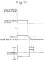
- FIGS 11 through 14 illustrate a second embodiment of an air-fuel ratio control according to the present invention.
- Fig. 11 illustrates the case where the operating state of the engine is shifted to an idling state in the same manner as that in Fig. 6, and Fig. 12 illustrates the case where the injection of fuel is stopped when the engine is decelerated in the same manner as that in Fig. 7.
- Fig. 13 illustrates the case where the operating state of the engine is shifted to a heavy load state in the same manner as that in Fig. 8. As can seen from Figs.
- the amount of the NO x absorbed and accumulated in the NO x absorbent 18 is gradually increased.
- the NO x absorbent 18 no longer can absorb the NO x . Accordingly, it is necessary to release the NO x from the NO x absorbent 18 before the absorbing ability of the NO x of the NO x absorbent 18 is saturated.
- the air-fuel mixture fed into the combustion chamber 3 is made rich for a relatively long time T o everytime the target air-fuel ratio of the air-fuel mixture fed into the combustion chamber 3 becomes the stoichiometric air-fuel ratio so that the NO x can be released from the NO x absorbent 18 in this time.
- the air-fuel mixture fed into the combustion chamber 3 may be made rich to release the NO x from the NO x absorbent 18 when a lean air-fuel mixture is burned.
- the air-fuel mixture is changed over from lean to rich as mentioned above, the amount of fuel injection is considerably increased.
- the air-fuel ratio of the air-fuel mixture fed into the combustion chamber is changed over from the stoichiometric air-fuel ratio to rich, the increase in the fuel consumption becomes smaller as compared with the case where the air-fuel mixture is changed over from lean to rich.
- the air-fuel mixture be made rich when the target air-fuel ratio of the air-fuel mixture fed into the combustion chamber 3 is the stoichiometric air-fuel ratio, as in the embodiment according to the present invention.
- the amount of the NO x absorbed and accumulated in the NO x absorbent 18 becomes smaller as the time during which a lean air-fuel mixture continues to be burned becomes shorter.
- the time T o during which the air-fuel mixture is made rich is made shorter as the time C during which a lean air-fuel mixture continues to be burned becomes shorter. Note that, the relationship between C and T o shown in Fig. 14 is stored in advance in the ROM 32.
- the air-fuel mixture is made rich when the injection of fuel is started, i.e., after the engine speed N drops considerably.
- the amount of air fed into the combustion chamber 3 per a unit time becomes smaller as the engine speed N becomes low.
- the amount of fuel to be increased becomes smaller as the engine speed-N becomes low. Therefore, as illustrated in Fig. 12, if the air-fuel mixture is made rich when the engine speed N drops, the amount of the fuel consumption can be reduced.
- the efficiency of the NO x releasing operation from the NO x absorbent 18 becomes high as the velocity of the exhaust gas flowing within the NO x absorbent 18 becomes low. Accordingly, as illustrated in Fig. 12, if the air-fuel mixture is made rich when the engine speed N drops considerably, a good releasing operation of the NO x from the NO x absorbent 18 can be obtained.
- the air-fuel ratio of the air-fuel mixture fed into the combustion chamber 3 is immediately changed over from rich to the stoichiometric air-fuel ratio. If the air-fuel ratio of the air-fuel mixture fed into the combustion chamber 3 is changed over from rich to the stoichiometric air-fuel ratio, since the accumulated carbons are burned out, the leakage of the ignition electric current ceases. As a result, since the engine speed N increases, it is possible to prevent the occurrence of an engine stall.
- Figures 15A and 15B illustrate a routine for executing the second embodiment of an air-fuel ratio control, and this routine is repeatedly executed. Note that, also in this second embodiment, the cut flag processing routine illustrated in Fig. 9 is used when controlling the air-fuel ratio.
- step 300 it is determined whether or not the cut flag indicating that the injection of fuel should be stopped is set.
- the routine goes to step 301, and it is determined whether or not the value of the correction coefficient K t is smaller than 1.0.
- K t ⁇ 1.0 i.e., the air-fuel mixture fed into the combustion chamber 3 is lean
- the routine goes to step 302, and the count value C is incremented by one. Then, the routine goes to step 304.
- the routine goes to step 303, and the count value C is made zero. Then, the routine goes to step 304. In addition, when the cut flag is set, the routine jumps to step 304 from step 300. Accordingly, the count value C represents a time during which a lean air-fuel mixture continues to be burned.
- step 304 it is determined whether or not the degree of the opening of the throttle valve 14 is the degree of the opening at idling.
- the routine goes to step 305, and it is determined whether or not the engine speed N is lower than 900 r.p.m. If N ⁇ 900 r.p.m., the routine goes to step 306. Namely, when the degree of the opening of the throttle valve 14 is the degree of the opening at idling, and the engine speed N is lower than 900 r.p.m., it is determined that the idling operation of the engine is carried out, and the routine goes to step 306.
- step 306 the value of the correction coefficient K is made 1.0, i.e., the target air-fuel ratio of the air-fuel mixture to be fed into the combustion chamber 3 is made the stoichiometric air-fuel ratio, and then the routine goes to step 308.
- the routine goes to step 307, and the value of the correction coefficient K is calculated from the engine speed N and the absolute pressure PM in the surge tank 10 on the basis of the relationship shown in Fig. 3. Then, the routine goes to step 308.
- step 308 it is determined whether or not the value of the correction coefficient K is equal to 1.0, i.e., the target air-fuel ratio of the air-fuel mixture to be fed into the combustion chamber 3 is the stoichiometric air-fuel ratio.
- K 1.0
- the routine goes to step 309, and it is determined whether or not a rich completion flag indicating that a process of temporarily making the air-fuel ratio rich is completed is set.
- the routine goes to step 310, and it is determined whether or not a rich flag indicating that the air-fuel mixture fed into the combustion chamber 3 should be temporarily made rich is set.
- This predetermined value KK is a value between about 1.1 and 1.2 which makes the air-fuel ratio of the air-fuel mixture a ratio between about 12.0:1 to 13.5:1.
- step 318 the routine goes to step 318 from step 310, and the count value T is incremented by one. Then, in step 319, it is determined whether or not the engine speed N has become lower than a fixed speed, for example, 500 r.p.m. If N ⁇ 500 r.p.m., the routine goes to step 320, and it is determined whether or not the count value T has become larger than the value T o . If T ⁇ T o , the routine goes to step 314.
- a fixed speed for example, 500 r.p.m.
- step 320 When it is determined in step 320 that the count value T has become larger than the value T o , the routine goes to step 321, and the rich completion flag is set. Then, in step 322, the rich flag is reset. Then, in step 323, the count value T is made zero, and then, in step 324, the value of the correction coefficient K t is made the value of the correction coefficient K. If the rich completion flag is set, the routine jumps to step 322 from step 309. Then, the routine goes to step 324 via step 323, and the value of the correction coefficient K t is made of the value of the correction coefficient K.
- the routine jumps to step 321 from step 319. Then, the routine goes to step 324 via steps 322 and 323, and the value of the correction coefficient K t is made the value of the correction coefficient K. Accordingly, at this time, the air-fuel ratio of the air-fuel mixture fed into the combustion chamber 3 is changed over from rich to the stoichiometric air-fuel ratio.
- step 308 When it is determined in step 308 that the correction coefficient K is not equal to 1.0, i.e., the target air-fuel ratio of the air-fuel mixture fed into the combustion chamber 3 is lean or rich, the routine goes to step 325, and the rich completion flag is reset. Then, the routine goes to step 324 via steps 322 and 323, and the value of the correction coefficient K t is made the value of the correction coefficient K. Accordingly, at this time, the air-fuel mixture fed into the combustion chamber 3 is made lean or rich as long as the cut flag is not set. Note that, where the cut flag is set, since the value of the correction coefficient K t is made zero at step 315, the injection of fuel is stopped.
- FIG. 16 illustrates a third embodiment according to the present invention.
- a HC concentration sensor 23 for detecting the concentration of HC in the exhaust gas is arranged in the exhaust passage 22 downstream of the NO x absorbent 18.
- This HC concentration sensor 23 produces an output voltage which is proportional to the concentration of HC, and this output voltage is input into the input port 35 via an AD converter 39.
- the HC concentration C CH in the exhaust gas flowing out from the NO x absorbent 18 is detected by the HC concentration sensor 23, and the air-fuel ratio of the air-fuel mixture fed into the combustion chamber 3 is changed over from rich to the stoichiometric air-fuel ratio when the HC concentration C HC exceeds a predetermined value ⁇ .
- Figures 17A and 17B illustrate-a -routine for executing the third embodiment of an air-fuel ratio control, and this routine is repeatedly executed. Note that, also in this second embodiment, the cut flag processing routine illustrated in Fig. 9 is used when controlling the air-fuel ratio.
- step 400 it is determined whether or not the degree of the opening of the throttle valve 14 is the degree of the opening at idling.
- the routine goes to step 401, and it is determined whether or not the engine speed N is lower than 900 r.p.m. If N ⁇ 900 r.p.m., the routine goes to step 402. Namely, when the degree of the opening of the throttle valve 14 is the degree of the opening at idling, and the engine speed N is lower than 900 r.p.m., it is determined that the idling operation of the engine is carried out, and the routine goes to step 402.
- step 402 the value of the correction coefficient K is made 1.0, i.e., the target air-fuel ratio of the air-fuel mixture to be fed into the combustion chamber 3 is made the stoichiometric air-fuel ratio, and then the routine goes to step 404.
- the routine goes to step 403 and the value of the correction coefficient K is calculated from the engine speed N and the absolute pressure PM in the surge tank 10 on the basis of the relationship shown in Fig. 3. Then, the routine goes to step 404.
- step 404 it is determined whether or not the value of the correction coefficient K is equal to 1.0, i.e., the target air-fuel ratio of the air-fuel mixture to be fed into the combustion chamber 3 is the stoichiometric air-fuel ratio.
- K 1.0
- the routine goes to step 405, and it is determined whether or not a rich completion flag indicating that a process of temporarily making the air-fuel ratio rich is completed is set.
- the routine goes to step 406, and the value of the correction coefficient K t is made a predetermined value KK.
- This predetermined value KK is a value between about 1.1 and 1.2 which makes the air-fuel ratio of the air-fuel mixture a ratio between about 12.0:1 to 13.5:1.
- step 408 When it is determined in step 408 that C HC > ⁇ , the routine goes to step 409, and the rich completion flag is set. Then, the routine goes to step 413 via steps 410 and 411 or via steps 410 and 412. If the rich completion flag is set, the routine goes to step 415 from step 405, and the value of the correction coefficient K t is made the value of the correction coefficient K. Then, the routine goes to step 413 via steps 410 and 411 or via steps 410 and 412.
- step 404 When it is determined in step 404 that the correction coefficient K is not equal to 1.0, i.e., the target air-fuel ratio of the air-fuel mixture fed into the combustion chamber 3 is lean or rich, the routine goes to step 414, and the rich completion flag is reset. Then, the routine goes to step 415, and the value of the correction coefficient K t is made the value of the correction coefficient K. Accordingly, at this time, the air-fuel mixture fed into the combustion chamber 3 is made lean or rich as long as the cut flag is not set. Note that, where the cut flag is set, since the value of the correction coefficient K t is made zero at step 411, the injection of fuel is stopped.
- the present invention when the engine operating region is changed over from a region in which a lean air-fuel mixture is burned to a region in which an air-fuel mixture of the stoichiometric air-fuel ratio should be burned, it is possible to prevent the NO x from being discharged into the outside air.
Claims (10)
- Moteur à combustion interne comprenant un dispositif d'épuration des gaz d'échappement dans un passage d'échappement, ledit dispositif comprenant:- un absorbant de NOx (18) disposé dans le passage d'échappement (16, 17) et absorbant le NOx lorsque le rapport air/carburant du gaz d'échappement s'écoulant dans ledit absorbant de NOx (18) est pauvre, ledit absorbant de NOx (18) libérant le NOx absorbé lorsque la concentration en oxygène dans le gaz d'échappement s'écoulant dans le dit absorbant de NOx (18) est diminué;- des moyens de détermination pour déterminer si la plage de fonctionnement du moteur est celle d'une première plage de fonctionnement du moteur dans laquelle le rapport air/carburant du mélange air/carburant alimentant le moteur (1) doit être rendu approximativement équivalent au rapport stoechiométrique air/carburant; ou celle d'une seconde plage de fonctionnement du moteur dans laquelle la quantité de carburant alimentant le moteur (1) est réduite à un niveau inférieur à la quantité de carburant nécessaire pour que le rapport air/carburant du mélange soit le rapport stoechiométrique; et- des moyens de contrôle du rapport air/carburant pour contrôler ledit rapport air/carburant du mélange air/carburant de sorte que ledit rapport air/carburant de ce mélange air/carburant soit approximativement rendu égal au rapport stoechiométrique air/carburant après enrichissement temporaire dudit rapport air/carburant du mélange air/carburant lorsqu'on passe de la seconde plage de fonctionnement du moteur à ladite première plage de fonctionnement du moteur.
- Moteur à combustion interne comprenant un dispositif d'épuration des gaz d'échappement selon la revendication 1, dans lequel ledit rapport air/carburant du mélange air/carburant de ladite seconde plage de fonctionnement du moteur est appauvri.
- Moteur à combustion interne comprenant un dispositif d'épuration des gaz d'échappement selon la revendication 2, dans lequel ladite première plage de fonctionnement du moteur (1) est une plage dans laquelle le moteur tourne au ralenti et ladite seconde plage de fonctionnement est une plage où le moteur (1) fonctionne à charge faible ou moyenne.
- Moteur à combustion interne comprenant un dispositif d'épuration des gaz d'échappement selon la revendication 3, dans lequel lesdits moyens de contrôle du mélange air/carburant ramènent instantanément ledit rapport air/carburant de celui du mélange riche à une valeur approximativement égale à celle du rapport stoechiométrique quand le régime du moteur tombe au dessous d'une vitesse prédéterminée durant la période où ledit rapport air/carburant du mélange air/carburant est temporairement sous forme du mélange riche.
- Moteur à combustion interne comprenant un dispositif d'épuration des gaz d'échappement selon la revendication 2, dans lequel ladite première plage de fonctionnement du moteur est une plage dans laquelle le moteur (1) fonctionne sous forte charge; et ladite seconde plage de fonctionnement du moteur (1) est une plage où le moteur fonctionne sous charge faible et moyenne.
- Moteur à combustion interne comprenant un dispositif d'épuration des gaz d'échappement selon la revendication 1, comprenant en outre un moyen pour arrêter l'alimentation en carburant du moteur (1) lorsque le moteur décélère; et pour ouvrir à nouveau l'alimentation en carburant du moteur (1) lorsque la vitesse tombe en dessous d'une vitesse prédéterminée, ladite première plage de fonctionnement du moteur étant une plage dans laquelle l'alimentation en carburant est ouverte; ladite seconde plage de fonctionnement du moteur étant une plage où l'alimentation en carburant est fermée; lesdits moyens de contrôle du rapport du mélange air/carburant enrichissant temporairement le rapport air/carburant du mélange air/carburant lorsque l'alimentation en carburant est réouverte.
- Moteur à combustion interne comprenant un dispositif d'épuration des gaz d'échappement selon la revendication 1, dans lequel ledit moyen de contrôle du rapport air/carburant du mélange air/carburant enrichissant temporairement le rapport air/carburant du mélange air/carburant pendant la durée qui est nécessaire pour libérer quasiment tout le NOx absorbé par ledit absorbant de NOx (18).
- Moteur à combustion interne comprenant un dispositif d'épuration des gaz d'échappement selon la revendication 7, dans lequel un moyen de calcul est prévu pour calculer la durée pendant laquelle un mélange air/carburant pauvre continue à être brûlé et calculer le raccourcissement de la durée pendant laquelle ledit rapport air/carburant du mélange air/carburant est temporairement enrichi alors que diminue la durée pendant laquelle le mélange air/carburant pauvre continue à brûler.
- Moteur à combustion interne comprenant un dispositif d'épuration des gaz d'échappement selon la revendication 1, comprenant en outre un moyen (23) pour mesurer la concentration en HC dans les gaz d'échappement dudit absorbant de NOx (18); lesdits moyens de contrôle du rapport air/carburant modifiant ledit rapport air/carburant du mélange air/carburant pour le faire passer de celui d'un mélange riche à approximativement celui du rapport stoechiométrique air/carburant lorsque ladite concentration en HC dépasse une valeur prédéterminée.
- Moteur à combustion interne comprenant un dispositif d'épuration des gaz d'échappement selon la revendication 1, dans lequel ledit absorbant de NOx (18) contient au moins une substance choisie parmi des métaux alcalins comprenant le potassium, le sodium, le lithium, le césium et des métaux alcalino-terreux comprenant le baryum et le calcium; et des métaux des terres rares comprenant le lanthane et l'yttrium et contient du platine.
Applications Claiming Priority (4)
| Application Number | Priority Date | Filing Date | Title |
|---|---|---|---|
| JP23489192 | 1992-09-02 | ||
| JP234891/92 | 1992-09-02 | ||
| JP127233/93 | 1993-05-28 | ||
| JP5127233A JP2692530B2 (ja) | 1992-09-02 | 1993-05-28 | 内燃機関 |
Publications (2)
| Publication Number | Publication Date |
|---|---|
| EP0585900A1 EP0585900A1 (fr) | 1994-03-09 |
| EP0585900B1 true EP0585900B1 (fr) | 1996-02-14 |
Family
ID=26463235
Family Applications (1)
| Application Number | Title | Priority Date | Filing Date |
|---|---|---|---|
| EP93113980A Expired - Lifetime EP0585900B1 (fr) | 1992-09-02 | 1993-09-01 | Appareil de dépollution de gaz d'échappement de moteur |
Country Status (4)
| Country | Link |
|---|---|
| US (1) | US5423181A (fr) |
| EP (1) | EP0585900B1 (fr) |
| JP (1) | JP2692530B2 (fr) |
| DE (1) | DE69301560T2 (fr) |
Families Citing this family (78)
| Publication number | Priority date | Publication date | Assignee | Title |
|---|---|---|---|---|
| JP3079933B2 (ja) * | 1995-02-14 | 2000-08-21 | トヨタ自動車株式会社 | 内燃機関の排気浄化装置 |
| US5784879A (en) * | 1995-06-30 | 1998-07-28 | Nippondenso Co., Ltd. | Air-fuel ratio control system for internal combustion engine |
| US5850815A (en) * | 1996-04-17 | 1998-12-22 | Honda Giken Kogyo Kabushiki Kaisha | Control system and control process in internal combustion engine |
| US5894725A (en) * | 1997-03-27 | 1999-04-20 | Ford Global Technologies, Inc. | Method and apparatus for maintaining catalyst efficiency of a NOx trap |
| US5832722A (en) * | 1997-03-31 | 1998-11-10 | Ford Global Technologies, Inc. | Method and apparatus for maintaining catalyst efficiency of a NOx trap |
| JPH10288065A (ja) * | 1997-04-17 | 1998-10-27 | Honda Motor Co Ltd | 内燃機関の空燃比制御装置 |
| EP0982487B1 (fr) | 1997-05-12 | 2003-07-16 | Toyota Jidosha Kabushiki Kaisha | Appareil de reduction des emissions de gaz d'echappement pour moteur a combustion interne |
| GB2326953A (en) * | 1997-06-30 | 1999-01-06 | Ford Motor Co | Motor vehicle exhaust Catalyst regeneration |
| DE19731624A1 (de) * | 1997-07-23 | 1999-01-28 | Volkswagen Ag | Verfahren und Vorrichtung zur Überwachung der De-Sulfatierung bei NOx-Speicherkatalysatoren |
| DE59807160D1 (de) * | 1997-07-19 | 2003-03-20 | Volkswagen Ag | Verfahren und Vorrichtung zur Überwachung der De-Sulfatierung bei NOx-Speicherkatalysatoren |
| DE19731623B4 (de) * | 1997-07-23 | 2006-11-23 | Volkswagen Ag | Verfahren und Vorrichtung zur De-Sulfatierung von NOx-Speichern bei Dieselmotoren |
| DE19741079C2 (de) * | 1997-09-18 | 2001-10-18 | Ford Global Tech Inc | Verfahren zur Regeneration einer Stickoxidfalle im Abgassystem eines Verbrennungsmotors |
| US5941211A (en) * | 1998-02-17 | 1999-08-24 | Ford Global Technologies, Inc. | Direct injection spark ignition engine having deceleration fuel shutoff |
| JP3663896B2 (ja) | 1998-03-18 | 2005-06-22 | 日産自動車株式会社 | エンジンの排気浄化装置 |
| DE19844082C1 (de) * | 1998-09-25 | 1999-10-14 | Siemens Ag | Verfahren zum Regenerieren eines NOx-Speicherkatalysators |
| JP3760053B2 (ja) * | 1998-09-30 | 2006-03-29 | 本田技研工業株式会社 | 内燃機関の排気ガス浄化装置 |
| JP3769944B2 (ja) | 1998-10-06 | 2006-04-26 | 日産自動車株式会社 | 内燃機関の排気浄化装置 |
| GB2350206A (en) * | 1999-05-11 | 2000-11-22 | Ford Motor Co | Switching between lean and rich fuel/air mixtures in an internal combustion engine |
| DE10020789C2 (de) * | 1999-05-19 | 2003-05-08 | Ford Global Tech Inc | Verfahren und System für den Übergang zwischen magerem und stöchiometrischem Kraftstoff-Luft-Verhältnis in einem mit magerer Verbrennung betriebenen Motor |
| JP3854013B2 (ja) * | 1999-06-10 | 2006-12-06 | 三菱電機株式会社 | 内燃機関の排出ガス浄化装置 |
| EP1108865A3 (fr) | 1999-12-13 | 2003-07-09 | Ford Global Technologies, Inc. | Construction d'un dispositif catalytique pour la traitement des gaz d'échappement pour un moteur à combustion de mélange faible |
| US6594989B1 (en) | 2000-03-17 | 2003-07-22 | Ford Global Technologies, Llc | Method and apparatus for enhancing fuel economy of a lean burn internal combustion engine |
| US6481199B1 (en) | 2000-03-17 | 2002-11-19 | Ford Global Technologies, Inc. | Control for improved vehicle performance |
| US6843051B1 (en) | 2000-03-17 | 2005-01-18 | Ford Global Technologies, Llc | Method and apparatus for controlling lean-burn engine to purge trap of stored NOx |
| US6360530B1 (en) | 2000-03-17 | 2002-03-26 | Ford Global Technologies, Inc. | Method and apparatus for measuring lean-burn engine emissions |
| US6708483B1 (en) | 2000-03-17 | 2004-03-23 | Ford Global Technologies, Llc | Method and apparatus for controlling lean-burn engine based upon predicted performance impact |
| US6327847B1 (en) | 2000-03-17 | 2001-12-11 | Ford Global Technologies, Inc. | Method for improved performance of a vehicle |
| US6427437B1 (en) | 2000-03-17 | 2002-08-06 | Ford Global Technologies, Inc. | Method for improved performance of an engine emission control system |
| US6434930B1 (en) | 2000-03-17 | 2002-08-20 | Ford Global Technologies, Inc. | Method and apparatus for controlling lean operation of an internal combustion engine |
| US6487850B1 (en) | 2000-03-17 | 2002-12-03 | Ford Global Technologies, Inc. | Method for improved engine control |
| US6539704B1 (en) | 2000-03-17 | 2003-04-01 | Ford Global Technologies, Inc. | Method for improved vehicle performance |
| US6629453B1 (en) | 2000-03-17 | 2003-10-07 | Ford Global Technologies, Llc | Method and apparatus for measuring the performance of an emissions control device |
| US6860100B1 (en) | 2000-03-17 | 2005-03-01 | Ford Global Technologies, Llc | Degradation detection method for an engine having a NOx sensor |
| US6374597B1 (en) | 2000-03-17 | 2002-04-23 | Ford Global Technologies, Inc. | Method and apparatus for accessing ability of lean NOx trap to store exhaust gas constituent |
| US6438944B1 (en) | 2000-03-17 | 2002-08-27 | Ford Global Technologies, Inc. | Method and apparatus for optimizing purge fuel for purging emissions control device |
| US6499293B1 (en) | 2000-03-17 | 2002-12-31 | Ford Global Technologies, Inc. | Method and system for reducing NOx tailpipe emissions of a lean-burn internal combustion engine |
| US6308697B1 (en) | 2000-03-17 | 2001-10-30 | Ford Global Technologies, Inc. | Method for improved air-fuel ratio control in engines |
| US6810659B1 (en) | 2000-03-17 | 2004-11-02 | Ford Global Technologies, Llc | Method for determining emission control system operability |
| US6487849B1 (en) | 2000-03-17 | 2002-12-03 | Ford Global Technologies, Inc. | Method and apparatus for controlling lean-burn engine based upon predicted performance impact and trap efficiency |
| US6477832B1 (en) | 2000-03-17 | 2002-11-12 | Ford Global Technologies, Inc. | Method for improved performance of a vehicle having an internal combustion engine |
| US6308515B1 (en) | 2000-03-17 | 2001-10-30 | Ford Global Technologies, Inc. | Method and apparatus for accessing ability of lean NOx trap to store exhaust gas constituent |
| US6370868B1 (en) | 2000-04-04 | 2002-04-16 | Ford Global Technologies, Inc. | Method and system for purge cycle management of a lean NOx trap |
| DE10023060B4 (de) * | 2000-05-11 | 2009-12-24 | Volkswagen Ag | Verfahren zur Bestimmung des Alterungszustandes sowie zur Durchführung der NOx-Regeneration eines NOx-Speicherkatalysators |
| US6389803B1 (en) | 2000-08-02 | 2002-05-21 | Ford Global Technologies, Inc. | Emission control for improved vehicle performance |
| DE10038458B4 (de) * | 2000-08-07 | 2012-06-21 | Volkswagen Ag | Vorrichtung und Verfahren zur Abgasreinigung |
| JP4389372B2 (ja) * | 2000-09-29 | 2009-12-24 | マツダ株式会社 | エンジンの燃料制御装置 |
| US6691507B1 (en) | 2000-10-16 | 2004-02-17 | Ford Global Technologies, Llc | Closed-loop temperature control for an emission control device |
| DE10054005A1 (de) | 2000-11-01 | 2002-05-08 | Daimler Chrysler Ag | Verfahren zum Betrieb einer Abgasreinigungsanlage mit Stickoxidspeicher |
| US6453666B1 (en) | 2001-06-19 | 2002-09-24 | Ford Global Technologies, Inc. | Method and system for reducing vehicle tailpipe emissions when operating lean |
| US6502387B1 (en) | 2001-06-19 | 2003-01-07 | Ford Global Technologies, Inc. | Method and system for controlling storage and release of exhaust gas constituents in an emission control device |
| US6694244B2 (en) | 2001-06-19 | 2004-02-17 | Ford Global Technologies, Llc | Method for quantifying oxygen stored in a vehicle emission control device |
| US6546718B2 (en) | 2001-06-19 | 2003-04-15 | Ford Global Technologies, Inc. | Method and system for reducing vehicle emissions using a sensor downstream of an emission control device |
| US6691020B2 (en) | 2001-06-19 | 2004-02-10 | Ford Global Technologies, Llc | Method and system for optimizing purge of exhaust gas constituent stored in an emission control device |
| US6650991B2 (en) | 2001-06-19 | 2003-11-18 | Ford Global Technologies, Llc | Closed-loop method and system for purging a vehicle emission control |
| US6615577B2 (en) | 2001-06-19 | 2003-09-09 | Ford Global Technologies, Llc | Method and system for controlling a regeneration cycle of an emission control device |
| US6463733B1 (en) | 2001-06-19 | 2002-10-15 | Ford Global Technologies, Inc. | Method and system for optimizing open-loop fill and purge times for an emission control device |
| US6490860B1 (en) | 2001-06-19 | 2002-12-10 | Ford Global Technologies, Inc. | Open-loop method and system for controlling the storage and release cycles of an emission control device |
| US6604504B2 (en) | 2001-06-19 | 2003-08-12 | Ford Global Technologies, Llc | Method and system for transitioning between lean and stoichiometric operation of a lean-burn engine |
| US6539706B2 (en) | 2001-06-19 | 2003-04-01 | Ford Global Technologies, Inc. | Method and system for preconditioning an emission control device for operation about stoichiometry |
| US6487853B1 (en) | 2001-06-19 | 2002-12-03 | Ford Global Technologies. Inc. | Method and system for reducing lean-burn vehicle emissions using a downstream reductant sensor |
| US6467259B1 (en) | 2001-06-19 | 2002-10-22 | Ford Global Technologies, Inc. | Method and system for operating dual-exhaust engine |
| US6553754B2 (en) | 2001-06-19 | 2003-04-29 | Ford Global Technologies, Inc. | Method and system for controlling an emission control device based on depletion of device storage capacity |
| US6568177B1 (en) | 2002-06-04 | 2003-05-27 | Ford Global Technologies, Llc | Method for rapid catalyst heating |
| US6769398B2 (en) | 2002-06-04 | 2004-08-03 | Ford Global Technologies, Llc | Idle speed control for lean burn engine with variable-displacement-like characteristic |
| US7032572B2 (en) * | 2002-06-04 | 2006-04-25 | Ford Global Technologies, Llc | Method for controlling an engine to obtain rapid catalyst heating |
| US7111450B2 (en) * | 2002-06-04 | 2006-09-26 | Ford Global Technologies, Llc | Method for controlling the temperature of an emission control device |
| US6868827B2 (en) | 2002-06-04 | 2005-03-22 | Ford Global Technologies, Llc | Method for controlling transitions between operating modes of an engine for rapid heating of an emission control device |
| US6735938B2 (en) | 2002-06-04 | 2004-05-18 | Ford Global Technologies, Llc | Method to control transitions between modes of operation of an engine |
| US6715462B2 (en) | 2002-06-04 | 2004-04-06 | Ford Global Technologies, Llc | Method to control fuel vapor purging |
| US7168239B2 (en) * | 2002-06-04 | 2007-01-30 | Ford Global Technologies, Llc | Method and system for rapid heating of an emission control device |
| US6725830B2 (en) | 2002-06-04 | 2004-04-27 | Ford Global Technologies, Llc | Method for split ignition timing for idle speed control of an engine |
| US6925982B2 (en) | 2002-06-04 | 2005-08-09 | Ford Global Technologies, Llc | Overall scheduling of a lean burn engine system |
| US6758185B2 (en) * | 2002-06-04 | 2004-07-06 | Ford Global Technologies, Llc | Method to improve fuel economy in lean burn engines with variable-displacement-like characteristics |
| US6745747B2 (en) | 2002-06-04 | 2004-06-08 | Ford Global Technologies, Llc | Method for air-fuel ratio control of a lean burn engine |
| US6736120B2 (en) * | 2002-06-04 | 2004-05-18 | Ford Global Technologies, Llc | Method and system of adaptive learning for engine exhaust gas sensors |
| US6736121B2 (en) | 2002-06-04 | 2004-05-18 | Ford Global Technologies, Llc | Method for air-fuel ratio sensor diagnosis |
| DE10253614B4 (de) | 2002-11-15 | 2008-12-24 | Audi Ag | Verfahren zum Betreiben einer Brennkraftmaschine eines Fahrzeugs, insbesondere eines Kraftfahrzeuges |
| JP4688670B2 (ja) * | 2005-12-20 | 2011-05-25 | 川崎重工業株式会社 | 内燃機関の燃焼制御装置および車両 |
Family Cites Families (18)
| Publication number | Priority date | Publication date | Assignee | Title |
|---|---|---|---|---|
| JPS51124738A (en) * | 1975-04-23 | 1976-10-30 | Nissan Motor Co Ltd | Air fuel ratio control apparatus |
| JPS59155549A (ja) * | 1983-02-23 | 1984-09-04 | Mitsubishi Electric Corp | 内燃機関の燃料制御装置 |
| DE3321424A1 (de) * | 1983-06-14 | 1984-08-16 | Robert Bosch Gmbh, 7000 Stuttgart | Regeleinrichtung fuer die gemischzusammensetzung einer mit gasfoermigem kraftstoff betriebenen brennkraftmaschine |
| JPS60111051A (ja) * | 1983-11-22 | 1985-06-17 | Suzuki Motor Co Ltd | 空燃比制御装置 |
| JPH0670388B2 (ja) * | 1984-09-05 | 1994-09-07 | 日本電装株式会社 | 空燃比制御装置 |
| JPS6297630A (ja) * | 1985-10-24 | 1987-05-07 | Nippon Shokubai Kagaku Kogyo Co Ltd | 窒素酸化物含有ガスから窒素酸化物を除去する方法 |
| JPS62106826A (ja) * | 1985-11-06 | 1987-05-18 | Nippon Shokubai Kagaku Kogyo Co Ltd | デイ−ゼル排ガス中の窒素酸化物を除去する方法 |
| JPS62117620A (ja) * | 1985-11-19 | 1987-05-29 | Nippon Shokubai Kagaku Kogyo Co Ltd | ガソリンエンジン排ガス中の窒素酸化物を除去する方法 |
| FR2647365B1 (fr) * | 1989-05-24 | 1991-08-30 | Inst Francais Du Petrole | Catalyseur multifonctionnel pour le traitement des gaz d'echappement des moteurs a combustion interne, contenant de l'uranium, au moins un promoteur de l'uranium et au moins un metal precieux et sa preparation |
| CA2024154C (fr) * | 1989-08-31 | 1995-02-14 | Senshi Kasahara | Catalyseur pour la reduction des oxydes d'azote dans le gaz d'echappement |
| JPH03124909A (ja) * | 1989-10-11 | 1991-05-28 | Mitsubishi Motors Corp | リーンバーンエンジンの排気ガス浄化装置 |
| JPH088975B2 (ja) * | 1989-10-20 | 1996-01-31 | 松下電器産業株式会社 | No▲下×▼除去装置 |
| JP2830464B2 (ja) * | 1989-12-06 | 1998-12-02 | トヨタ自動車株式会社 | 内燃機関の排気浄化装置 |
| JP2712758B2 (ja) * | 1990-05-28 | 1998-02-16 | トヨタ自動車株式会社 | 内燃機関の排気浄化装置 |
| JP3046051B2 (ja) * | 1990-09-28 | 2000-05-29 | マツダ株式会社 | エンジンの排気ガス浄化装置 |
| US5174111A (en) * | 1991-01-31 | 1992-12-29 | Toyota Jidosha Kabushiki Kaisha | Exhaust gas purification system for an internal combustion engine |
| JP2887933B2 (ja) * | 1991-03-13 | 1999-05-10 | トヨタ自動車株式会社 | 内燃機関の排気浄化装置 |
| KR960002348B1 (ko) * | 1991-10-03 | 1996-02-16 | 도요다 지도오샤 가부시끼가이샤 | 내연기관의 배기정화장치 |
-
1993
- 1993-05-28 JP JP5127233A patent/JP2692530B2/ja not_active Expired - Lifetime
- 1993-09-01 DE DE69301560T patent/DE69301560T2/de not_active Expired - Lifetime
- 1993-09-01 US US08/114,894 patent/US5423181A/en not_active Expired - Lifetime
- 1993-09-01 EP EP93113980A patent/EP0585900B1/fr not_active Expired - Lifetime
Also Published As
| Publication number | Publication date |
|---|---|
| DE69301560D1 (de) | 1996-03-28 |
| EP0585900A1 (fr) | 1994-03-09 |
| JPH06129246A (ja) | 1994-05-10 |
| JP2692530B2 (ja) | 1997-12-17 |
| US5423181A (en) | 1995-06-13 |
| DE69301560T2 (de) | 1996-09-19 |
Similar Documents
| Publication | Publication Date | Title |
|---|---|---|
| EP0585900B1 (fr) | Appareil de dépollution de gaz d'échappement de moteur | |
| EP0581279B1 (fr) | Dispositif de purification des gaz d'échappement pour moteur à combustion | |
| EP0598916B1 (fr) | Systeme de limitation d'emission de gaz d'echappement pour moteur a combustion interne | |
| EP0560991B1 (fr) | Dispositif pour purifier les gaz d'echappement d'un moteur a combustion interne | |
| EP0573672B1 (fr) | Dispositif limitant l'emission des gaz d'echappement dans un moteur a combustion interne | |
| US5577382A (en) | Exhaust purification device of internal combustion engine | |
| EP0636770B1 (fr) | Dispositif de nettoyage de gaz d'echappement pour moteur a combustion interne | |
| EP0597106B1 (fr) | Dispositif d'echappement et d'epuration pour moteurs a combustion interne | |
| EP0598917B1 (fr) | Systeme de limitation d'emission de gaz d'echappement pour moteur a combustion interne | |
| JP2600492B2 (ja) | 内燃機関の排気浄化装置 | |
| US5388403A (en) | Exhaust gas purification device for an engine | |
| JP2998481B2 (ja) | 内燃機関の排気浄化装置 | |
| JP3309626B2 (ja) | 内燃機関の排気浄化装置 | |
| JP2743764B2 (ja) | 内燃機関の排気浄化装置 | |
| JP2743760B2 (ja) | 内燃機関の排気浄化装置 | |
| JP2914067B2 (ja) | 内燃機関の排気浄化装置 | |
| JPH07166913A (ja) | 内燃機関の排気浄化装置 | |
| JP3070376B2 (ja) | 内燃機関の排気浄化装置 | |
| JPH07189660A (ja) | 内燃機関の排気浄化装置 | |
| JP2658757B2 (ja) | 内燃機関の排気浄化装置 | |
| JPH10176522A (ja) | 内燃機関の排気浄化装置 | |
| JP3508192B2 (ja) | 内燃機関の排気浄化装置 | |
| JP3509584B2 (ja) | 内燃機関の排気浄化装置 | |
| JPH07127495A (ja) | 内燃機関の排気浄化装置 |
Legal Events
| Date | Code | Title | Description |
|---|---|---|---|
| PUAI | Public reference made under article 153(3) epc to a published international application that has entered the european phase |
Free format text: ORIGINAL CODE: 0009012 |
|
| 17P | Request for examination filed |
Effective date: 19930901 |
|
| AK | Designated contracting states |
Kind code of ref document: A1 Designated state(s): DE FR GB |
|
| 17Q | First examination report despatched |
Effective date: 19950210 |
|
| GRAA | (expected) grant |
Free format text: ORIGINAL CODE: 0009210 |
|
| AK | Designated contracting states |
Kind code of ref document: B1 Designated state(s): DE FR GB |
|
| REF | Corresponds to: |
Ref document number: 69301560 Country of ref document: DE Date of ref document: 19960328 |
|
| ET | Fr: translation filed | ||
| PLBI | Opposition filed |
Free format text: ORIGINAL CODE: 0009260 |
|
| PLBF | Reply of patent proprietor to notice(s) of opposition |
Free format text: ORIGINAL CODE: EPIDOS OBSO |
|
| 26 | Opposition filed |
Opponent name: DR. ING. H.C. F. PORSCHE AKTIENGESELLSCHAFT Effective date: 19961114 |
|
| PLBF | Reply of patent proprietor to notice(s) of opposition |
Free format text: ORIGINAL CODE: EPIDOS OBSO |
|
| PLBO | Opposition rejected |
Free format text: ORIGINAL CODE: EPIDOS REJO |
|
| PLBN | Opposition rejected |
Free format text: ORIGINAL CODE: 0009273 |
|
| STAA | Information on the status of an ep patent application or granted ep patent |
Free format text: STATUS: OPPOSITION REJECTED |
|
| 27O | Opposition rejected |
Effective date: 19980410 |
|
| REG | Reference to a national code |
Ref country code: GB Ref legal event code: IF02 |
|
| PGFP | Annual fee paid to national office [announced via postgrant information from national office to epo] |
Ref country code: GB Payment date: 20120829 Year of fee payment: 20 |
|
| PGFP | Annual fee paid to national office [announced via postgrant information from national office to epo] |
Ref country code: FR Payment date: 20120926 Year of fee payment: 20 Ref country code: DE Payment date: 20120829 Year of fee payment: 20 |
|
| REG | Reference to a national code |
Ref country code: DE Ref legal event code: R071 Ref document number: 69301560 Country of ref document: DE |
|
| REG | Reference to a national code |
Ref country code: GB Ref legal event code: PE20 Expiry date: 20130831 |
|
| PG25 | Lapsed in a contracting state [announced via postgrant information from national office to epo] |
Ref country code: DE Free format text: LAPSE BECAUSE OF EXPIRATION OF PROTECTION Effective date: 20130903 |
|
| PG25 | Lapsed in a contracting state [announced via postgrant information from national office to epo] |
Ref country code: GB Free format text: LAPSE BECAUSE OF EXPIRATION OF PROTECTION Effective date: 20130831 |