EP0487948B1 - Procédé et dispositif pour placer des caneaux dans la surface des matériaux panneaux doux et usage de ce dispositif - Google Patents
Procédé et dispositif pour placer des caneaux dans la surface des matériaux panneaux doux et usage de ce dispositif Download PDFInfo
- Publication number
- EP0487948B1 EP0487948B1 EP19910118899 EP91118899A EP0487948B1 EP 0487948 B1 EP0487948 B1 EP 0487948B1 EP 19910118899 EP19910118899 EP 19910118899 EP 91118899 A EP91118899 A EP 91118899A EP 0487948 B1 EP0487948 B1 EP 0487948B1
- Authority
- EP
- European Patent Office
- Prior art keywords
- section
- cutting edge
- cutter
- cutting
- sections
- Prior art date
- Legal status (The legal status is an assumption and is not a legal conclusion. Google has not performed a legal analysis and makes no representation as to the accuracy of the status listed.)
- Expired - Lifetime
Links
Images


Classifications
-
- B—PERFORMING OPERATIONS; TRANSPORTING
- B26—HAND CUTTING TOOLS; CUTTING; SEVERING
- B26D—CUTTING; DETAILS COMMON TO MACHINES FOR PERFORATING, PUNCHING, CUTTING-OUT, STAMPING-OUT OR SEVERING
- B26D3/00—Cutting work characterised by the nature of the cut made; Apparatus therefor
- B26D3/06—Grooving involving removal of material from the surface of the work
-
- B—PERFORMING OPERATIONS; TRANSPORTING
- B26—HAND CUTTING TOOLS; CUTTING; SEVERING
- B26D—CUTTING; DETAILS COMMON TO MACHINES FOR PERFORATING, PUNCHING, CUTTING-OUT, STAMPING-OUT OR SEVERING
- B26D7/00—Details of apparatus for cutting, cutting-out, stamping-out, punching, perforating, or severing by means other than cutting
- B26D7/08—Means for treating work or cutting member to facilitate cutting
- B26D7/086—Means for treating work or cutting member to facilitate cutting by vibrating, e.g. ultrasonically
-
- Y—GENERAL TAGGING OF NEW TECHNOLOGICAL DEVELOPMENTS; GENERAL TAGGING OF CROSS-SECTIONAL TECHNOLOGIES SPANNING OVER SEVERAL SECTIONS OF THE IPC; TECHNICAL SUBJECTS COVERED BY FORMER USPC CROSS-REFERENCE ART COLLECTIONS [XRACs] AND DIGESTS
- Y10—TECHNICAL SUBJECTS COVERED BY FORMER USPC
- Y10T—TECHNICAL SUBJECTS COVERED BY FORMER US CLASSIFICATION
- Y10T83/00—Cutting
- Y10T83/02—Other than completely through work thickness
- Y10T83/0304—Grooving
Definitions
- the invention relates to a method for introducing surface channels with an at least approximately rectangular cross section into sheet material made of soft material, in particular mineral fiber insulation mats or sheets made of a styrene polymer, in which a motorized cutting tool with an oscillating cutting knife is used.
- the invention further relates to a device for introducing surface channels with an at least approximately rectangular cross section in sheet material made of soft material, in particular mineral fiber insulation mats or sheets made of a styrene polymer, with a motor-driven cutting tool, in which a cutting knife about an axis with an angular amplitude in Range between about 0.5 ° and 7 ° and a frequency in the range of about 10,000 to 25,000 min -1 is oscillated and the cutting knife has angled sections that are at least partially provided with a cutting edge.
- a cutting tool of the type already explained is also known, in which an oscillating cutting knife is also used.
- the cutting knife has a 90 ° bent blade, the two legs of which are each provided with a cutting edge.
- This known cutting knife is provided for the sole purpose of cutting through elastic adhesive beads on vehicle windows.
- This special tool is neither intended nor suitable for other areas of application. In particular, this tool is unsuitable for making surface channels in soft material plate material because the outer leg of the blade extends parallel to the lower surface of the power tool and the oscillating shaft forms an acute angle with the cutting edges, so that cutting into surfaces of plate material is impossible is.
- the invention has for its object to develop a method and a device of the type mentioned, with which it is possible to introduce surface channels in a short and simple and reproducible manner in plate material made of soft material.
- this object is achieved on the one hand in that a U-shaped cutting knife, the cutting edge of which rotates around the sections forming the U, is guided in a straight line through the plate material.
- this object is achieved in that, in a first step, an L-shaped cutting knife, the cutting edge of which rotates around the sections forming the L, is guided essentially in a straight line through the plate material, and in a second step Cutting knife with a straight section is guided parallel to the guidance of the first step through the plate material such that a continuous strip of plate material can be removed from the plate material.
- the first and second steps are preferably carried out several times in succession, in parallel and next to one another, in order to introduce wide surface channels.
- the object on which the invention is based is achieved, on the one hand, by the cutting edge rotating over at least three sections which form a U with one another.
- the object on which the invention is based is achieved in that at least one cutting knife is provided, in which the cutting edge rotates over at least two sections which are angled to one another, and that at least one cutting knife is provided which is not angled .
- the U-shaped knife of the one embodiment according to the invention with a total of at least three cutting edges namely causes a complete surface channel to be cut out in a single operation, the cutting line leading from surface to surface.
- the angled, preferably L-shaped knife of the other embodiment according to the invention with a total of two cutting edges causes two sides of the surface channel to be cut out in a first operation, while the third side is subsequently cut out in a second operation.
- This has the advantage that surface channels of any width can be produced by performing the two work steps as often as desired next to one another and in parallel.
- the L-shaped knife is then used to cut out a further strip of material on the underside on one side of the channel that has already been cut out, which is cut in the longitudinal direction in a further second operation with a straight cutting knife or, if appropriate, again with an angled cutting knife and can be removed or falls out.
- the cut-out material residue can only be removed from the cut channel, but does not need to be separated out, so that in practice no operation is required at all, because the cut-out material migrates out of the cut-out channel by itself or with an inclined work surface falls out.
- At least one of the sections forming the free ends of the U is followed by a further section which is angled by approximately 90 °.
- this measure has the advantage that the further section can serve as a support on the surface of the plate material, so that when the surface channel is cut, an uncontrolled sinking of the knife into the plate material is prevented becomes.
- the angled section is provided on the outer, free end of the U-forming section, extends towards the clamping side and is supported on one of the sections on the clamping side. Since the outer part of the cutting edge is thus additionally supported, the mechanical stability of the cutting edge is considerably improved in this way.
- the support can be achieved in a simple manner in that the angled section is welded to one of the sections on the clamping side, which can be achieved, for example, by spot welding.
- the cutting knife comprises a blade holder for inserting an exchangeable blade.
- This measure has the advantage that with one and the same blade holder, surface channels of different widths, depths or other contours can be cut in close succession, with only minimal changeover times being required.
- the blade is U-shaped and can be locked with its free ends in slots in the blade holder.
- a non-angled cutting knife can be inserted into the cutting tool.
- This measure has the advantage that the strips of material that have already been loosened on one or both sides on the second or third side can be cut out with a straight, non-angled cutting knife.
- the cutting edge is not straight at its cutting edge, but rather is serrated or wavy.
- the cutting knife is provided with a smooth cutting edge on one side in a cutting direction and with a serrated or wavy cutting edge on the other side in the opposite cutting direction.
- This measure has the advantage that one and the same tool can be used for two different materials. If the tool with the clamped cutting knife is to be used in a fibrous material, it only needs to be guided through the material in one cutting direction with the smooth cutting edge, while with another, rather coarse material, the tool in the opposite cutting direction with the serrated or wavy edge is passed through the material.
- This is a great advantage, particularly when it comes to interior fittings, if, on the one hand, mineral fiber mats and, on the other hand, styrene polymer plates are used in parallel or immediately one after the other, both of which are known to be used for thermal insulation. The tradesman then does not need to change the cutting knife, but rather can process both materials with an unchanged tool, only the tool having to be guided through the material once in one direction and the other time.
- the cutting edge runs in an arc shape, preferably along a convex arc. This measure also has the advantage that a better cut is produced in numerous applications, be it with straight or serrated or wavy cutting edges along the arc shape.
- This embodiment of the knives also has advantages in terms of cut quality in numerous applications.
- exemplary embodiments of the invention are preferred in which the axis is at right angles to a first one Clamping section of the cutting knife adjacent and provided with the cutting edge extends.
- This known measure has the advantage that the motor-driven cutting tool can be guided with its longitudinal axis perpendicular to the surface of the material, which is ergonomically advantageous in numerous applications and ensures good access to the material.
- 10 denotes an electric tool with a housing 11, which is only indicated schematically and broken off.
- a drive flange 12 is connected to the front of the housing 11, which preferably contains an electric drive motor, which flange e.g. can contain an angular gear.
- the drive flange 12 is also provided with a protective bracket 13.
- An axis 14 extends at right angles to the longitudinal axis of the housing 11 and is at the same time the axis of a drive spindle 15 in the drive flange 12.
- a double arrow 16 indicates that the drive spindle 15 moves in an oscillating manner, ie rotates back and forth by a small angular amount.
- the angular amount is approximately between 0.5 ° and 7 °, the oscillation frequency between 10,000 and 25,000 min -1 .
- a cutting knife 20 is inserted into the drive spindle 15, the further details of which are shown in FIGS. 2 and 3.
- the cutting knife 20 comprises a first, flat section 21, which is followed by a second, inclined section 22. This is followed by a third, flat section 23, from which a fourth section 24 extends vertically downward.
- the fourth section 24 merges via a fifth section 25 bent by 180 ° into a sixth section 26 which runs vertically upwards.
- the upper free leg of the sixth section 26 merges again into a seventh section 27 which runs flat and is directed towards the third section 23.
- a cutting edge 29 is continuously attached in the fourth, fifth and sixth sections 24, 25, 26, which together form a U-shaped structure.
- the first, flat section 21 merges to the right in FIGS. 2 and 3 into a circular extension 30 which is provided with a central driving profile 31, for example a polygon, which forms a torsionally rigid driving connection for the drive spindle 15.
- FIGS. 4 and 5 show a slightly modified exemplary embodiment of a cutting knife 20a, in which the first to third sections 21a to 23a are combined to form a common inclined section which runs at an angle 35 of, for example, 15 ° with respect to a horizontal plane.
- the cutting knife 20a also has a U-shaped shape, but does not have a flat section at the left free end of the U in the illustration in FIGS. 4 and 5, as is present in the embodiment of FIGS. 2 and 3 with 27 .
- a cutting edge 29a goes around the three sections of the U.
- FIG. 6 shows a further exemplary embodiment of a cutting knife 40.
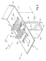
- the cutting knife 40 has a blade holder 41 which can be brought into a rotationally fixed driving connection with the drive spindle 15, for example with the aid of a circular section, as can be seen at 30, 31 in FIG. 3. For the sake of clarity, however, this is not shown again in FIG. 6.
- the blade holder 41 has a first, inclined section 42 and a second, flat section 43. Slits 45a, 45b, 46a, 46b are made in the flat section 43, the total number of which is a multiple of 2. The slots 45a, 45b, 46a, 46b are arranged in pairs in a folding symmetry to one another.
- the slots 45a, 45b, 46a, 46b each represent a U-shaped opening in the second, flat section 43 in plan view, the slots 45a, 45b on the left in FIG. 6 being arranged in a folding-symmetrical manner with respect to the two right slots 46a, 46b are.
- Each of the slots 45a, 45b, 46a, 46b has a continuous longitudinal wall 50 and 52 and, on the opposite side, a tongue 51 and 53 directed against the longitudinal wall 50, 52.
- the tongues 51a, 51b are directed to the right, over the tongues 53a, 53b of the two slots 46a, 46b located on the right in FIG. 6 are directed opposite to the left.
- the cutting knife 40 further comprises a separate, U-shaped blade 60.
- the blade 60 has a first, vertical section 61, a second, flat section 62 adjoining it below, and a third, in turn adjoining and vertically running section 63.
- the three sections 61, 62, 63 mentioned are in turn provided with a continuous cutting edge 64a or at the opposite end 64b.
- the free ends of the vertical sections 61 and 64 are provided with horizontally extending slots 70 and 71, respectively.
- the width of the slots 70, 71 is equal to or slightly larger than the width of the tongues 51 and 53, while the total width of the vertical sections 61, 63 is equal to or slightly less than the total width of the U-shaped slots 45 and 46 is.
- the arrangement is preferably such that the vertical sections 61, 63 of the blade 60 are moved slightly towards one another with the fingers of the user, that is to say are pressed together, as indicated by a double arrow 75 in FIG. 6. In this position, the free ends of the vertical sections 61, 63 can be guided past the tongues 51, 53 of the slots 45, 46 until a desired depth of cut T is achieved by inserting said free ends into the slots 45, 46.
- the blade 60 has a width B, so that the slots 45a, 46a are to be used, which are also spaced apart by the dimension B.
- the slots 45b, 46b which are spaced further apart are provided for this purpose.
- the cutting depth T can be varied by changing the slot 70, 71 in engagement in each case.
- one and the same blade 60 can be used, whereas different blades usually have to be used for different widths B.
- FIG. 7 shows a section of an extremely schematically indicated plate material made of soft material, namely a glass fiber or rock wool insulation mat 80.
- the mat 80 is provided on a flat surface with an aluminum liner 81, as is usually used as a vapor barrier in such insulation mats becomes.
- FIG. 7 shows, as an example, the case in which a cutting knife 20 is used, as has already been shown and explained in FIGS. 1 to 3.
- the cutting knife 20 is connected to the drive spindle 15 of the power tool 10 and the drive is then switched on.
- the cutting knife 20 then oscillates with the values mentioned at the beginning.
- the cutting knife 20 can now either be brought laterally to the mat 80 laterally or can be dipped obliquely at any location into the surface 84 of the mat 80 in order to cut out a surface channel 82 from the material of the mat 80.
- the cutting knife 20 is guided so that the third and seventh, each flat section 23 and 27 of the cutting knife 20 is guided along the surface 84 of the mat 80 so that it serves as a vertical stop and an undefined sinking of the cutting knife 20 into the mat 80 is prevented.
- the oscillating cutting knife 20 is now guided in a straight line along the surface 84, as indicated by an arrow 83 in FIG. 7.
- straight means that a predetermined course of the channel to be formed is followed, which of course can also be curved at least in places.
- the term "rectilinear” is therefore only intended to illustrate that the channel 82 to be formed is an elongated structure.
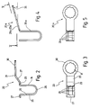
- 90 denotes another embodiment of a cutting knife.
- the special feature of this cutting knife is that a first straight section 91, which is used to fasten the cutting knife 90 to the power tool 10 of FIG. 1, passes straight into a second section 92 of the cutting knife, that is to say it is not angled or bent.
- the second section 92 is followed by a third, curved section 93, which in turn merges into a fourth, straight section 94, which runs parallel to the second section 92.
- the side view of FIG. 10, which is rotated by 90 ° in relation to the view of FIG. 8, shows the resulting shape of a U.
- the second, the third and the fourth section 92, 93, 94 are provided with a cutting edge which runs over all three sections 92, 93, 94.
- the cutting edge 95 is serrated.
- the serrated design of the cutting edge 95 is particularly advantageous for coarsely structured materials, e.g. Styrene polymers as are generally known under the registered trademark "STYROPOR".
- Such materials consist of material balls with a diameter of 1 or more mm. If such materials are cut with straight or already blunted knives, the material balls are not cut but rather jump out of the material elastically when cutting. This leads to unclean cut edges and contamination in the area around the workplace. It has now been found that such materials can be advantageously cut with serrated or wavy cutting edges, especially when the distance between the serrations or waves is at least as large as the diameter of the beads.
- FIG. 9 Another variant of a cutting knife 90 ', as shown in FIG. 9, is finally provided with a straight cutting edge 95b. 9 corresponds completely to the cutting knife 90 of FIG. 8. Accordingly, the side view of FIG. 10 rotated by 90 ° is the same in all cases.
- FIG. 9 it is also indicated with 95b 'that the cutting knife 90' can be provided with different cutting edges on the right and left side in FIG. 9. While the right-hand side in FIG. 9 is provided with a straight but serrated cutting edge 95b, the left-hand side in FIG. 9 is provided with a likewise straight but smooth cutting edge 95b '. This is intended to indicate that the cutting knives can be provided with different cutting edges 95b and 95b ', regardless of their other shape in the two possible cutting directions right / left, so that one and the same cutting knife 90' can be used for cutting two different materials can and only the cutting direction, ie the direction in which the tool is guided must be changed.
- 96 denotes an axis about which the cutting blades 90 and 90 'execute the oscillating movement.
- the oscillating drive axis 14 is at an angle of 90 ° to the longitudinal axis of the housing 11. Therefore, if one of the cutting knives 90, 90 'shown in Figs. 8-10 is used with this cutting tool 10, the cutting edges 95 and 95b are aligned with the longitudinal sections 92 and 94 in extension of the longitudinal axis of the cutting tool 10 while they are being cut included an angle of 90 ° with the longitudinal axis of the cutting tool 10 in the previously described exemplary embodiments.
- FIGS. 8 to 10 can also be designed in an angled or cranked arrangement, similar to FIGS. 1 to 7 his and the same applies in reverse to the previously described exemplary embodiments of FIGS. 1 to 7, which can also be designed in a non-angled or non-angled embodiment.
- FIGS. 11 to 14 show further exemplary embodiments of cutting knives, the shape of which in side view is not U-shaped but L-shaped or even straight.
- FIG. 11 shows a cutting knife 100 with a first, straight fastening section 101, to which in turn a second, likewise straight section 102 is directly connected.
- the arrangement corresponds to the sections 91, 92 of the cutting knife 90 according to FIG. 8.
- the second, straight section 102 of the cutting knife 100 is now provided with a cutting edge 103 which is corrugated in the exemplary embodiment shown.
- a cutting edge 103 which is corrugated in the exemplary embodiment shown.
- the considerations apply, which have already been made above with regard to FIGS. 8 to 10 with regard to corrugated or serrated cutters, and it goes without saying that the design of the cutting edges is only to be understood as an example, because all of them are described in the context of the present invention Cutting knives with continuous, serrated or wavy cutting edges, whether straight or curved.
- a cutting knife 100 ′ is only provided with the second straight section 102.
- a cutting knife 100 '' Provide a third, also straight section 104 at the lower free end of the second straight section 102 with an angle of 90 °.
- a cutting knife 100 ′′ ′′ is provided at the lower end of the second straight section 102 with a likewise angled third section 104a, which, however, adjoins the second straight section 102 at an obtuse angle.
- FIGS. 11 to 14 are used in different ways compared to what was described above for FIGS. 1 to 10.
- an angled cutting knife 100 '' or 100 ''' is used to make a first longitudinal cut through the plate material.
- the surface channel is already cut out on two of three sides.
- the third side of the surface channel is then cut out in a further work step, either in that an angled cutting knife 100 '' or 100 '''is passed through the plate material in the opposite direction, so that essentially the cutting edge 103 on the second straight section 102 cuts out the third side of the surface channel.
- a straight cutting knife 100 ' can be used to cut out the third side of the surface channel.
- the two operations can then be repeated one or more times.
- the angled cutting knife 100 ′′ is then guided through the surface channel that has already been introduced, in which the second, straight section 102 slides on one of the side walls of the surface channel and the third, angled section 104 laterally carries out a further horizontal cut.
- the material strip which has already been loosened on one side in this way is then in turn separated by a second cut using the cutting knife 100 ′′ or 100 ′.
- 15 to 22 show further exemplary embodiments of the invention, in which additional support of the free leg of the U-shaped cutting edge is provided.
- the cutting knife generally designated by the number 110a in FIGS. 19 and 20 essentially corresponds to the cutting knife according to FIGS. 9 and 10, but an additional support of the outer free leg of the U-forming section is provided on the clamping-side section.
- the cutting knife 110a has a first flat section 112a, on which a circular extension with a driving profile 120a in the form of a polygon is provided.
- the driving profile 120a is used for connection to the drive spindle 15 of the power tool 10, by means of which the cutting knife 110a can be moved in an oscillating manner about the axis 118a.
- the first flat section 112a merges into the U-shaped cutting edge 119a, which is formed from a part of the first section 112a, from a bent section 113a and a third flat section 114a, which is parallel to the first section 112a.
- the third flat section 114a continues with a section 115a angled at an angle of approximately 90 ° in the direction of the first flat section 112a.
- the fourth angled section 115a is followed by another fifth section 116a angled at an angle of approximately 90 °, which runs parallel to the first planar section 112a.
- the fifth section 116a lies on the first flat section 112a and is connected to it by a spot weld 117a.
- the U-shaped cutting edge 119a is thus terminated at the upper end via the fourth and fifth sections 115a, 116a and is supported on the first section 112a.
- the cutting edge 119a is serrated as in the previously mentioned exemplary embodiment according to FIGS. 9 and 10.
- the embodiment designated 110 differs from the previously described embodiment according to FIGS. 19 and 20 only in that the cutting edge 119 is straight and has no serrations.
- the cutting edge 119 tapers towards both ends of the cutting knife 110, so that a cut is possible in both directions.
- 17 and 18 show a modification of the exemplary embodiment according to FIGS. 2 and 3.
- the cutting knife 140 comprises a first, flat section 142, which is followed by a second, inclined section 143. This is followed by a third, vertical section 144 which merges into a fourth section 145 which is bent by 180 °. At the end of the curved section 145 is included another section 146 perpendicular to the first section 142 and running parallel to the third section 144.
- the U-shaped cutting edge 151 is formed by the two legs of the third section 144 and the fifth section 146, as well as by the bent section 145 lying between them.
- the fifth section 146 merges at a right angle at its end remote from the bent section 145 into a sixth angled section 147, which is followed by a further inclined section 148.
- This inclined section 148 abuts the second inclined section 143 and is connected to it by a spot weld 119.
- the U-shaped cutting edge 151 is also supported on the clamping side via the angled section 147 and the inclined section 148, so that greater stability is achieved and the risk of breakage is reduced.
- the cutting edge 151 is formed on both sides on the sections 144, 145, 146, so that the cutting knife 140 can be used in both cutting directions.
- the exemplary embodiment denoted overall by the number 140a in FIGS. 21 and 22 differs from the exemplary embodiment described with reference to FIGS. 17 and 18 only in that the cutting edge 151a is designed in a serrated manner.
- the cutting edge 151a is only formed on one side of the cutting knife 140a in the exemplary embodiment shown, it is also readily conceivable to form it on both sides in order to enable cutting on both sides.
Landscapes
- Life Sciences & Earth Sciences (AREA)
- Forests & Forestry (AREA)
- Engineering & Computer Science (AREA)
- Mechanical Engineering (AREA)
- Knives (AREA)
- Processing And Handling Of Plastics And Other Materials For Molding In General (AREA)
Claims (22)
- Procédé destiné à pratiquer des canaux de surface (82) de section transversale au moins approximativement rectangulaire dans des plaques en matériau souple, en particulier des plaques isolantes en fibres minérales (80) ou des plaques en polystyrène, dans lequel on utilise un outil de coupe (10) motorisé avec couteau (20 ; 40 ; 90 ; 110 ; 110a ; 140 ; 140a) oscillant, caractérisé en ce qu'un couteau (20 ; 20a ; 40 ; 90 ; 90' ; 110 ; 110a ; 140 ; 140a) en U, dont la lame (29 ; 29a ; 64 ; 95 ; 119 ; 119a ; 151 ; 151a) passe autour des portions (24, 25, 26 ; 61, 62, 63 ; 92, 93, 94 ; 112, 113; 114 ; 112a; 113a; 114a ; 144; 145; 146 ; 144a; 145a; 146a) formant le U, est guidé essentiellement en ligne droite (83) par les plaques.
- Procédé destiné à pratiquer des canaux de surface (82) de section transversale au moins approximativement rectangulaire dans des plaques en matériau souple, en particulier des plaques isolantes en fibres minérales (80) ou des plaques en polystyrène, dans lequel on utilise un outil de coupe motorisé avec couteau (100, 100', 100'') oscillant, caractérisé en ce qu'au cours d'une première étape, un couteau (100'') en L, dont la lame (103) passe autour des portions (102, 104) formant le L, est guidé sensiblement en ligne droite par les plaques, et en ce qu'au cours d'une deuxième étape, un couteau (100') avec une portion droite (102) est guidé parallèlement au guidage de la première étape, par les plaques, de manière qu'une bande continue de plaque puisse être prélevée des plaques.
- Procédé selon la revendication 2, caractérisé en ce que pour pratiquer des canaux de surface larges la première et la deuxième étapes sont exécutées de façon multiple, l'une après l'autre, parallèlement et côte à côte.
- Dispositif destiné à pratiquer des canaux de surface (82) de section transversale au moins approximativement rectangulaire dans des plaques en matériau souple, en particulier des plaques isolantes en fibres minérales (80) ou des plaques en polystyrène, avec un outil de coupe motorisé dans lequel un couteau (20 ; 20a ; 40 ; 90 ; 90' ; 110 ; 110a ; 140 ; 140a) est déplacé en oscillations autour d'un axe (14 ; 96 ; 118 ; 118a ; 150 ; 150a) avec une amplitude angulaire comprise entre 0,5° et 7° et une fréquence de l'ordre de 10 000 à 25 000 min-1 et le couteau (20 ; 20a ; 40 ; 90 ; 90' ; 110 ; 110a ; 140 ; 140a) présente des portions (21 à 27 ; 42, 43, 61 à 63 ; 92, 93, 94 ; 112 à 116 ; 112a à 116a ; 142 à 148 ; 142a à 148a) coudées les unes par rapport aux autres, qui sont dotées au moins en partie d'une lame (29 ; 29a, 64 ; 95 ; 119 ; 119a, 151 ; 151a), caractérisé en ce que la lame (29 ; 29a ; 64 ; 95 ; 119 ; 119a ; 151 ; 151a) passe sur au moins trois portions (24 à 26 ; 61 à 63 ; 92, 93, 94 ; 112 à 114 ; 112a à 114a ; 144 à 146 ; 144a à 146a), qui forment entre elles un U.
- Dispositif selon la revendication 4, caractérisé en ce qu'à l'une au moins des portions (24, 26 ; 61, 63 ; 114 ; 114a ; 146 ; 146a), formant les extrémités libres du U, fait suite une autre portion (23, 27 ; 43 ; 43 ; 115 ; 115a ; 147 ; 147a), coudée approximativement à 90°.
- Dispositif selon la revendication 5, caractérisé en ce que la portion coudée (23, 24 ; 43) s'étend vers l'extérieur, en s'éloignant du côté de serrage.
- Dispositif selon la revendication 5, caractérisé en ce que la portion coudée (115, 115a ; 147, 147a) est prévue à l'extrémité libre extérieure de la portion (114, 114a, 146, 146a) formant le U, s'étend en direction du côté de serrage et est soutenue contre l'une des portions (112, 112a, 143, 143a, sur le côté de serrage.
- Dispositif selon la revendication 7, caractérisé en ce que la portion coudée (115, 115a, 147, 147a) est soudée avec l'une des portions (112, 112a, 143, 143a), sur le côté de serrage.
- Dispositif selon l'une des revendications 4 à 8, caractérisé en ce que le couteau (40) comprend un porte-lame (41) pour l'insertion d'une lame (60) interchangeable.
- Dispositif selon la revendication 9, caractérisé en ce que la lame (60) est en U et peut être bloquée avec ses extrémités libres dans des fentes (45, 46) du porte-lame (41).
- Dispositif selon la revendication 10, caractérisé en ce que pour pratiquer des canaux (82) de largeur (B) différente, plusieurs fentes (45a, 45b, 46a, 46b) parallèles sont prévues dans le porte-lame (41).
- Dispositif selon la revendication 10 ou 11, caractérisé en ce que pour pratiquer des canaux (82) de profondeur (T) différente, sont prévus des moyens d'arrêt, qui autorisent un blocage de l'extrémité libre dans les fentes (45, 46), à des hauteurs différentes.
- Dispositif selon la revendication 12, caractérisé en ce que les moyens d'arrêt se présentent comme des languettes (51, 53) dans les fentes (45, 46), qui s'engagent dans des contre-fentes (70, 71) des extrémités libres.
- Dispositif destiné à pratiquer des canaux de surface (82) de section transversale au moins approximativement rectangulaire dans des plaques en matériau souple, en particulier des plaques isolantes en fibres minérales (80) ou des plaques en polystyrène, avec un outil de coupe motorisé dans lequel un couteau (100', 100'', 100''') est déplacé en oscillations autour d'un axe (105) avec une amplitude angulaire comprise entre 0,5° et 7° et une fréquence de l'ordre de 10 000 à 25 000 min-1 et le couteau (100', 100'', 100''') présente au moins une portion pourvue d'une lame (103), un couteau coudé (100'', 100''') au moins étant prévu, dans lequel la lame (103) passe sur au moins deux portions (102, 104 ; 102, 104), caractérisé en ce qu'il est prévu au moins un couteau (100') qui n'est pas coudé.
- Dispositif selon la revendication 14, caractérisé en ce que le couteau (100'') coudé présente une lame (103), qui comprend deux portions (102, 104) coudées l'une par rapport à l'autre en forme de L.
- Dispositif selon une ou plusieurs des revendications 4 à 15, caractérisé en ce que la lame (95, 119a, 151a) est dentelée.
- Dispositif selon une ou plusieurs des revendications 4 à 15, caractérisé en ce que la lame (103) est ondulée.
- Dispositif selon la revendication 16 ou 17, caractérisé en ce que le couteau (90') est pourvu sur un côté, dans un sens de coupe, d'une lame lisse (95b') et sur l'autre côté, dans le sens de coupe opposé, d'une lame dentelée ou ondulée (95b).
- Dispositif selon une ou plusieurs des revendications 4 à 18, caractérisé en ce que la lame (95) s'étend en arc.
- Dispositif selon la revendication 19, caractérisé en ce que la lame (95) s'étend le long d'un arc convexe.
- Dispositif selon une ou plusieurs des revendications 4 à 20, caractérisé en ce qu'au moins l'une des portions (102), pourvue d'une lame (103a), se rétrécit.
- Dispositif selon une ou plusieurs des revendications 4 à 21, caractérisé en ce que l'axe (105) s'étend à angle droit par rapport à une première portion (102), adjacente à une portion de serrage (101) du couteau (100) et pourvue de la lame (103).
Applications Claiming Priority (4)
| Application Number | Priority Date | Filing Date | Title |
|---|---|---|---|
| DE4037790 | 1990-11-28 | ||
| DE4037790 | 1990-11-28 | ||
| DE4107989 | 1991-03-13 | ||
| DE4107989 | 1991-03-13 |
Publications (3)
| Publication Number | Publication Date |
|---|---|
| EP0487948A2 EP0487948A2 (fr) | 1992-06-03 |
| EP0487948A3 EP0487948A3 (en) | 1993-01-20 |
| EP0487948B1 true EP0487948B1 (fr) | 1997-08-27 |
Family
ID=25898822
Family Applications (1)
| Application Number | Title | Priority Date | Filing Date |
|---|---|---|---|
| EP19910118899 Expired - Lifetime EP0487948B1 (fr) | 1990-11-28 | 1991-11-06 | Procédé et dispositif pour placer des caneaux dans la surface des matériaux panneaux doux et usage de ce dispositif |
Country Status (5)
| Country | Link |
|---|---|
| US (1) | US5231910A (fr) |
| EP (1) | EP0487948B1 (fr) |
| JP (1) | JPH05116096A (fr) |
| DE (2) | DE4135573A1 (fr) |
| TW (1) | TW213877B (fr) |
Cited By (4)
| Publication number | Priority date | Publication date | Assignee | Title |
|---|---|---|---|---|
| WO2012059287A1 (fr) | 2010-11-05 | 2012-05-10 | Robert Bosch Gmbh | Outil de meulage et/ou de coupe pour une machine-outil à entraînement oscillant |
| DE102011075692A1 (de) | 2011-05-12 | 2012-11-15 | Robert Bosch Gmbh | Schleif- bzw. Schneidwerkzeug für eine Werkzeugmaschine mit Oszillationsantrieb |
| WO2013029868A1 (fr) | 2011-09-02 | 2013-03-07 | Robert Bosch Gmbh | Outil de rectification ou de coupe destiné à une machine-outil à entraînement rotatif |
| US10307917B2 (en) | 2014-09-22 | 2019-06-04 | Worktools, Inc. | Cutting blade for oscillating tool |
Families Citing this family (31)
| Publication number | Priority date | Publication date | Assignee | Title |
|---|---|---|---|---|
| DE19518750C1 (de) * | 1995-05-22 | 1996-09-26 | Sprimag Spritzmaschbau Gmbh | Verfahren zur Herstellung von rotationssymmetrischen Profilwalzen mit über ihre Länge unterschiedlichen Profilen aus elastisch komprimierbaren Schaumstoffen |
| DE19613537C2 (de) * | 1996-04-03 | 1998-04-09 | Engelbert Gmeilbauer | Schälmesser |
| DE19613538C1 (de) * | 1996-04-03 | 1997-07-10 | Engelbert Gmeilbauer | Schneidmesser |
| US20010041524A1 (en) * | 1997-05-28 | 2001-11-15 | Marco Steiger | Material removing tool |
| EP0881023B8 (fr) | 1997-05-28 | 2006-01-11 | maRoc GmbH | Outil de coupe abrasif ou à dents de coupe |
| GB2345875B (en) | 1999-05-25 | 2001-05-30 | Uponor Ltd | Pipe preparing tool V |
| US6418831B1 (en) * | 1999-06-11 | 2002-07-16 | Nrg Industries, Inc. | Tool holder and tab system for board cutting machine |
| DE19932248A1 (de) | 1999-07-10 | 2001-01-11 | Fein C & E | Schneidmesser zum Durchtrennen von Klebewulsten an Fensterscheiben |
| US7632274B2 (en) * | 2000-02-16 | 2009-12-15 | Trans1 Inc. | Thin cutter blades with retaining film for preparing intervertebral disc spaces |
| US6558390B2 (en) | 2000-02-16 | 2003-05-06 | Axiamed, Inc. | Methods and apparatus for performing therapeutic procedures in the spine |
| US20070260270A1 (en) * | 2000-02-16 | 2007-11-08 | Trans1 Inc. | Cutter for preparing intervertebral disc space |
| DE20003499U1 (de) * | 2000-02-25 | 2000-05-18 | C. & E. Fein Gmbh & Co, 70176 Stuttgart | Schneidmesser |
| DE10022641B4 (de) * | 2000-04-28 | 2015-12-10 | Volkswagen Ag | Verfahren zur Herstellung einer Reißnaht als Sollbruchstelle |
| DE10058894A1 (de) * | 2000-11-23 | 2002-06-06 | C & E Fein Gmbh & Co Kg | Werkzeug mit einem Halter zur Befestigung an einer Antriebswelle |
| DE10164081B4 (de) * | 2001-12-19 | 2012-01-26 | C. & E. Fein Gmbh | Oszillationswerkzeug mit Ausgleichsabschnitt |
| US6640446B2 (en) * | 2001-12-21 | 2003-11-04 | Leo Martinez | Floor groover |
| US7776042B2 (en) | 2002-12-03 | 2010-08-17 | Trans1 Inc. | Methods and apparatus for provision of therapy to adjacent motion segments |
| CA2543295A1 (fr) * | 2003-10-23 | 2005-05-06 | Trans1 Inc. | Instruments et kits d'instruments pour effectuer des micromanipulations chirurgicales sur la colonne vertebrale |
| FR2861627B1 (fr) * | 2003-11-03 | 2006-06-23 | Pierre Grehal Et Cie Ets | Dispositif de decoupe de passages techniques dans un bloc de materiau isolant |
| JP2008515648A (ja) * | 2004-10-08 | 2008-05-15 | ソシエテ ド テクノロジー ミシュラン | 予備組立てゴム製品の切断 |
| DE102004050635A1 (de) * | 2004-10-18 | 2006-04-20 | C. & E. Fein Gmbh | Hartschaum-Trägerplatte zur Aufnahme der Heizrohre einer Fußbodenheizung sowie Werkzeug zum Einarbeiten des Verlegekanals und Verfahren zum Verlegen von Heizrohren in der Hartschaum-Trägerplatte |
| DE102005027195A1 (de) * | 2005-06-06 | 2006-12-14 | C. & E. Fein Gmbh | Verfahren und Vorrichtung zum Herstellen von Schlitzen in Werkstücken |
| US20080033466A1 (en) * | 2006-02-28 | 2008-02-07 | Trans1 Inc. | Surgical cutter with exchangeable cutter blades |
| WO2009145058A1 (fr) * | 2008-05-26 | 2009-12-03 | 三星ダイヤモンド工業株式会社 | Appareil de découpe pour pile solaire à couches minces |
| US8650760B2 (en) * | 2009-12-30 | 2014-02-18 | Guy A. Van Alstine | Heated cutting blade, cutting head, and blade mounting structure |
| US8696672B2 (en) * | 2010-01-22 | 2014-04-15 | Baxano Surgical, Inc. | Abrading tool for preparing intervertebral disc spaces |
| US9302405B2 (en) * | 2011-10-28 | 2016-04-05 | Robert Bosch Gmbh | Planer accessory tool for an oscillating power tool |
| DE102012007489A1 (de) | 2012-03-30 | 2013-10-02 | C. & E. Fein Gmbh | Spachtel |
| WO2014159225A2 (fr) | 2013-03-14 | 2014-10-02 | Baxano Surgical, Inc. | Implants rachidiens et système d'implantation |
| US9555554B2 (en) | 2013-05-06 | 2017-01-31 | Milwaukee Electric Tool Corporation | Oscillating multi-tool system |
| DE102013107867A1 (de) | 2013-07-23 | 2015-02-19 | C. & E. Fein Gmbh | Oszillationswerkzeug |
Family Cites Families (13)
| Publication number | Priority date | Publication date | Assignee | Title |
|---|---|---|---|---|
| US3740847A (en) * | 1971-02-04 | 1973-06-26 | W Kliever | Power driven meat trimming and cutting knife |
| US4080734A (en) * | 1976-09-24 | 1978-03-28 | Barbour Deryle R | Method and apparatus for removing a vehicle windshield |
| FI800489A (fi) * | 1980-02-19 | 1981-08-20 | Partek Ab | Saett att framstaella isolationsskaolar foer roer och anordning foer utfoerande av saettet |
| JPS58177302A (ja) * | 1982-04-10 | 1983-10-18 | 松岡 伝人 | 木材の方形孔切削形成装置 |
| DE8325025U1 (de) * | 1983-08-31 | 1983-12-22 | C. & E. Fein Gmbh & Co, 7000 Stuttgart | Schneidwerkzeug |
| US4615119A (en) * | 1984-04-26 | 1986-10-07 | Jhj Enterprises | Blade for a vibratory cutter |
| DE8423004U1 (de) * | 1984-08-02 | 1984-10-31 | C. & E. Fein Gmbh & Co, 7000 Stuttgart | Schneidmesser zum durchtrennen der klebeschicht einer angeklebten scheibe |
| US4656910A (en) * | 1986-03-03 | 1987-04-14 | The Goodyear Tire & Rubber Company | Belt skiving method and apparatus |
| DE3719073A1 (de) * | 1987-06-06 | 1988-12-15 | Fein C & E | Schneidwerkzeug |
| JPH01163052A (ja) * | 1987-12-19 | 1989-06-27 | Sumitomo Rubber Ind Ltd | グルービング装置のカッタ支持装置 |
| DE3814554A1 (de) * | 1988-04-29 | 1989-11-09 | Fein C & E | Schneidmesser |
| DE3839029A1 (de) * | 1988-11-18 | 1990-05-23 | Fein C & E | Schneidmesser mit geradem schneidteil |
| DE3929852A1 (de) * | 1989-08-15 | 1991-02-21 | Fein C & E | Schaelmesser |
-
1991
- 1991-10-29 DE DE19914135573 patent/DE4135573A1/de not_active Withdrawn
- 1991-11-06 DE DE59108835T patent/DE59108835D1/de not_active Expired - Fee Related
- 1991-11-06 EP EP19910118899 patent/EP0487948B1/fr not_active Expired - Lifetime
- 1991-11-18 TW TW80109040A patent/TW213877B/zh active
- 1991-11-22 US US07/796,573 patent/US5231910A/en not_active Expired - Fee Related
- 1991-11-27 JP JP33599591A patent/JPH05116096A/ja active Pending
Cited By (7)
| Publication number | Priority date | Publication date | Assignee | Title |
|---|---|---|---|---|
| WO2012059287A1 (fr) | 2010-11-05 | 2012-05-10 | Robert Bosch Gmbh | Outil de meulage et/ou de coupe pour une machine-outil à entraînement oscillant |
| DE102010043452A1 (de) | 2010-11-05 | 2012-05-10 | Robert Bosch Gmbh | Schleif- bzw. Schneidwerkzeug für eine Werkzeugmaschine mit Oszillationsantrieb |
| DE102011075692A1 (de) | 2011-05-12 | 2012-11-15 | Robert Bosch Gmbh | Schleif- bzw. Schneidwerkzeug für eine Werkzeugmaschine mit Oszillationsantrieb |
| WO2012152482A1 (fr) | 2011-05-12 | 2012-11-15 | Robert Bosch Gmbh | Outil de meulage, de sciage ou de coupe pour une machine-outil à entraînement oscillant |
| WO2013029868A1 (fr) | 2011-09-02 | 2013-03-07 | Robert Bosch Gmbh | Outil de rectification ou de coupe destiné à une machine-outil à entraînement rotatif |
| DE102011082035A1 (de) | 2011-09-02 | 2013-03-07 | Robert Bosch Gmbh | Schleif- bzw. Schneidwerkzeug für eine Werkzeugmaschine mit Drehantrieb |
| US10307917B2 (en) | 2014-09-22 | 2019-06-04 | Worktools, Inc. | Cutting blade for oscillating tool |
Also Published As
| Publication number | Publication date |
|---|---|
| DE4135573A1 (de) | 1992-06-04 |
| EP0487948A2 (fr) | 1992-06-03 |
| DE59108835D1 (de) | 1997-10-02 |
| EP0487948A3 (en) | 1993-01-20 |
| JPH05116096A (ja) | 1993-05-14 |
| US5231910A (en) | 1993-08-03 |
| TW213877B (fr) | 1993-10-01 |
Similar Documents
| Publication | Publication Date | Title |
|---|---|---|
| EP0487948B1 (fr) | Procédé et dispositif pour placer des caneaux dans la surface des matériaux panneaux doux et usage de ce dispositif | |
| DE3905788C2 (de) | Schneidwerkzeug zum Einschneiden von Rohren, um deren Biegung zu erleichtern | |
| DE3018985C2 (de) | Verfahren zum Verarbeiten von natürlich gewachsenen, sich konisch verjüngenden Baumstämmen | |
| EP0546392B1 (fr) | Lame pour le découpage ainsi que dispositif avec celle-ci | |
| DE2725187C2 (de) | Einrichtung zum Durchtrennen von I-Profilen oder verwandten Profilen | |
| DE3403668C2 (fr) | ||
| DE2921176A1 (de) | Schlag- oder stanzeinrichtung | |
| DE19605991A1 (de) | Eckverbindungsmaschine zur Herstellung von Fenster- und/oder Türrahmen | |
| DE20013640U1 (de) | Spülebecken | |
| EP0497078A1 (fr) | Outil pour couper des panneaux d'isolation notamment pour ceux constitués d'une matière fibreuse | |
| EP0538720A1 (fr) | Procédé de fabrication d'une barette suspendue comme un pendule pour hacher pour un dispositif de hachage, barette pour hacher et dispositif de hachage | |
| DE2752717A1 (de) | Stanzmesserform und deren herstellungsverfahren | |
| EP0813929A1 (fr) | Procédé de fabrication de panneaux de tÔles d'acier soudés | |
| EP2524756A1 (fr) | Dispositif de coupe de profilé | |
| EP0266609A1 (fr) | Armoire, en particulier armoire pour salles de bains | |
| DE2718296A1 (de) | Vorrichtung zum aufrauhen der schmalseite eines blattstapels | |
| DE60204888T2 (de) | Rotierendes standwerkzeug zum kontinuierlischen lochen von profilen sowie verwendung desselben | |
| EP1160392A2 (fr) | Panneau de façade extrudé | |
| EP0157161A1 (fr) | Rondins, fraiseuse pour leur réalisation et construction réalisée avec ces rondins | |
| DE2027725C3 (de) | Verfahren und Vorrichtung zum Herstellen von mit einer Klebefolie o.dgl. hinterlegten Einzelstücken gleicher oder unterschiedlicher Größe aus einer ebenen Platte | |
| EP0181431A2 (fr) | Procédé pour le découpage par sciage des pièces à travailler | |
| DE3935626A1 (de) | Stanzmesser | |
| DE19824616C2 (de) | Schnittwerkzeug für textile Beläge im Fahrzeugbau | |
| DE10345287B4 (de) | Werkzeug zum faserfreien Schneiden von Verkleidungen, Belägen oder ähnlichem | |
| EP0663174B1 (fr) | Dispositif culinaire pour couper des fruits, des légumes ou des produits similaires |
Legal Events
| Date | Code | Title | Description |
|---|---|---|---|
| PUAI | Public reference made under article 153(3) epc to a published international application that has entered the european phase |
Free format text: ORIGINAL CODE: 0009012 |
|
| AK | Designated contracting states |
Kind code of ref document: A2 Designated state(s): CH DE FR GB IT LI NL SE |
|
| PUAL | Search report despatched |
Free format text: ORIGINAL CODE: 0009013 |
|
| RHK1 | Main classification (correction) |
Ipc: B26D 3/08 |
|
| AK | Designated contracting states |
Kind code of ref document: A3 Designated state(s): CH DE FR GB IT LI NL SE |
|
| 17P | Request for examination filed |
Effective date: 19930317 |
|
| 17Q | First examination report despatched |
Effective date: 19950522 |
|
| GRAG | Despatch of communication of intention to grant |
Free format text: ORIGINAL CODE: EPIDOS AGRA |
|
| GRAH | Despatch of communication of intention to grant a patent |
Free format text: ORIGINAL CODE: EPIDOS IGRA |
|
| GRAH | Despatch of communication of intention to grant a patent |
Free format text: ORIGINAL CODE: EPIDOS IGRA |
|
| GRAA | (expected) grant |
Free format text: ORIGINAL CODE: 0009210 |
|
| AK | Designated contracting states |
Kind code of ref document: B1 Designated state(s): CH DE FR GB IT LI NL SE |
|
| PG25 | Lapsed in a contracting state [announced via postgrant information from national office to epo] |
Ref country code: IT Free format text: LAPSE BECAUSE OF FAILURE TO SUBMIT A TRANSLATION OF THE DESCRIPTION OR TO PAY THE FEE WITHIN THE PRE;WARNING: LAPSES OF ITALIAN PATENTS WITH EFFECTIVE DATE BEFORE 2007 MAY HAVE OCCURRED AT ANY TIME BEFORE 2007. THE CORRECT EFFECTIVE DATE MAY BE DIFFERENT FROM THE ONE RECORDED.SCRIBED TIME-LIMIT Effective date: 19970827 Ref country code: NL Free format text: LAPSE BECAUSE OF FAILURE TO SUBMIT A TRANSLATION OF THE DESCRIPTION OR TO PAY THE FEE WITHIN THE PRESCRIBED TIME-LIMIT Effective date: 19970827 |
|
| REG | Reference to a national code |
Ref country code: CH Ref legal event code: NV Representative=s name: TROESCH SCHEIDEGGER WERNER AG Ref country code: CH Ref legal event code: EP |
|
| REF | Corresponds to: |
Ref document number: 59108835 Country of ref document: DE Date of ref document: 19971002 |
|
| ET | Fr: translation filed | ||
| GBT | Gb: translation of ep patent filed (gb section 77(6)(a)/1977) |
Effective date: 19971010 |
|
| PG25 | Lapsed in a contracting state [announced via postgrant information from national office to epo] |
Ref country code: SE Effective date: 19971127 |
|
| NLV1 | Nl: lapsed or annulled due to failure to fulfill the requirements of art. 29p and 29m of the patents act | ||
| PLBE | No opposition filed within time limit |
Free format text: ORIGINAL CODE: 0009261 |
|
| STAA | Information on the status of an ep patent application or granted ep patent |
Free format text: STATUS: NO OPPOSITION FILED WITHIN TIME LIMIT |
|
| 26N | No opposition filed | ||
| PGFP | Annual fee paid to national office [announced via postgrant information from national office to epo] |
Ref country code: FR Payment date: 20000914 Year of fee payment: 10 |
|
| PGFP | Annual fee paid to national office [announced via postgrant information from national office to epo] |
Ref country code: GB Payment date: 20001013 Year of fee payment: 10 |
|
| PGFP | Annual fee paid to national office [announced via postgrant information from national office to epo] |
Ref country code: CH Payment date: 20001016 Year of fee payment: 10 |
|
| PG25 | Lapsed in a contracting state [announced via postgrant information from national office to epo] |
Ref country code: GB Free format text: LAPSE BECAUSE OF NON-PAYMENT OF DUE FEES Effective date: 20011106 |
|
| PG25 | Lapsed in a contracting state [announced via postgrant information from national office to epo] |
Ref country code: LI Free format text: LAPSE BECAUSE OF NON-PAYMENT OF DUE FEES Effective date: 20011130 Ref country code: CH Free format text: LAPSE BECAUSE OF NON-PAYMENT OF DUE FEES Effective date: 20011130 |
|
| REG | Reference to a national code |
Ref country code: GB Ref legal event code: IF02 |
|
| GBPC | Gb: european patent ceased through non-payment of renewal fee |
Effective date: 20011106 |
|
| REG | Reference to a national code |
Ref country code: CH Ref legal event code: PL |
|
| PG25 | Lapsed in a contracting state [announced via postgrant information from national office to epo] |
Ref country code: FR Free format text: LAPSE BECAUSE OF NON-PAYMENT OF DUE FEES Effective date: 20020730 |
|
| REG | Reference to a national code |
Ref country code: FR Ref legal event code: ST |
|
| REG | Reference to a national code |
Ref country code: FR Ref legal event code: ST |
|
| PGFP | Annual fee paid to national office [announced via postgrant information from national office to epo] |
Ref country code: DE Payment date: 20081103 Year of fee payment: 18 |
|
| PG25 | Lapsed in a contracting state [announced via postgrant information from national office to epo] |
Ref country code: DE Free format text: LAPSE BECAUSE OF NON-PAYMENT OF DUE FEES Effective date: 20100601 |