EP0456210B1 - Méthode pour traiter un matériau photographique à l'halogénure d'argent et matériau photosensible pour photographie - Google Patents
Méthode pour traiter un matériau photographique à l'halogénure d'argent et matériau photosensible pour photographie Download PDFInfo
- Publication number
- EP0456210B1 EP0456210B1 EP91107481A EP91107481A EP0456210B1 EP 0456210 B1 EP0456210 B1 EP 0456210B1 EP 91107481 A EP91107481 A EP 91107481A EP 91107481 A EP91107481 A EP 91107481A EP 0456210 B1 EP0456210 B1 EP 0456210B1
- Authority
- EP
- European Patent Office
- Prior art keywords
- processing
- light
- sensitive material
- photographic
- processing solution
- Prior art date
- Legal status (The legal status is an assumption and is not a legal conclusion. Google has not performed a legal analysis and makes no representation as to the accuracy of the status listed.)
- Expired - Lifetime
Links
- 238000012545 processing Methods 0.000 title claims description 444
- 239000000463 material Substances 0.000 title claims description 249
- 238000000034 method Methods 0.000 title claims description 141
- -1 silver halide Chemical class 0.000 title claims description 80
- 229910052709 silver Inorganic materials 0.000 title claims description 55
- 239000004332 silver Substances 0.000 title claims description 55
- 239000000839 emulsion Substances 0.000 claims description 53
- 238000007599 discharging Methods 0.000 claims description 5
- 239000000243 solution Substances 0.000 description 198
- 239000010410 layer Substances 0.000 description 58
- 230000008569 process Effects 0.000 description 45
- 238000011161 development Methods 0.000 description 36
- 235000010724 Wisteria floribunda Nutrition 0.000 description 32
- 239000000975 dye Substances 0.000 description 27
- XLYOFNOQVPJJNP-UHFFFAOYSA-N water Substances O XLYOFNOQVPJJNP-UHFFFAOYSA-N 0.000 description 24
- 150000001875 compounds Chemical class 0.000 description 22
- 239000003795 chemical substances by application Substances 0.000 description 20
- 239000007844 bleaching agent Substances 0.000 description 19
- 150000003839 salts Chemical class 0.000 description 14
- 239000002253 acid Substances 0.000 description 13
- 238000010276 construction Methods 0.000 description 13
- 230000006641 stabilisation Effects 0.000 description 13
- 238000011105 stabilization Methods 0.000 description 13
- 239000000203 mixture Substances 0.000 description 12
- 230000002829 reductive effect Effects 0.000 description 12
- 239000003570 air Substances 0.000 description 9
- 238000000576 coating method Methods 0.000 description 9
- 238000001035 drying Methods 0.000 description 9
- 238000003672 processing method Methods 0.000 description 9
- 230000001235 sensitizing effect Effects 0.000 description 9
- 239000000126 substance Substances 0.000 description 9
- 239000000084 colloidal system Substances 0.000 description 8
- 230000035945 sensitivity Effects 0.000 description 8
- 239000011248 coating agent Substances 0.000 description 7
- 239000007788 liquid Substances 0.000 description 7
- 206010070834 Sensitisation Diseases 0.000 description 6
- MTHSVFCYNBDYFN-UHFFFAOYSA-N diethylene glycol Chemical compound OCCOCCO MTHSVFCYNBDYFN-UHFFFAOYSA-N 0.000 description 6
- 238000010438 heat treatment Methods 0.000 description 6
- 239000003112 inhibitor Substances 0.000 description 6
- DZVCFNFOPIZQKX-LTHRDKTGSA-M merocyanine Chemical compound [Na+].O=C1N(CCCC)C(=O)N(CCCC)C(=O)C1=C\C=C\C=C/1N(CCCS([O-])(=O)=O)C2=CC=CC=C2O\1 DZVCFNFOPIZQKX-LTHRDKTGSA-M 0.000 description 6
- 230000008313 sensitization Effects 0.000 description 6
- GEHJYWRUCIMESM-UHFFFAOYSA-L sodium sulfite Chemical compound [Na+].[Na+].[O-]S([O-])=O GEHJYWRUCIMESM-UHFFFAOYSA-L 0.000 description 6
- 230000008961 swelling Effects 0.000 description 6
- 238000005406 washing Methods 0.000 description 6
- 239000002699 waste material Substances 0.000 description 6
- CPELXLSAUQHCOX-UHFFFAOYSA-M Bromide Chemical compound [Br-] CPELXLSAUQHCOX-UHFFFAOYSA-M 0.000 description 5
- 229920002284 Cellulose triacetate Polymers 0.000 description 5
- VTLYFUHAOXGGBS-UHFFFAOYSA-N Fe3+ Chemical compound [Fe+3] VTLYFUHAOXGGBS-UHFFFAOYSA-N 0.000 description 5
- 108010010803 Gelatin Proteins 0.000 description 5
- BQCADISMDOOEFD-UHFFFAOYSA-N Silver Chemical compound [Ag] BQCADISMDOOEFD-UHFFFAOYSA-N 0.000 description 5
- NNLVGZFZQQXQNW-ADJNRHBOSA-N [(2r,3r,4s,5r,6s)-4,5-diacetyloxy-3-[(2s,3r,4s,5r,6r)-3,4,5-triacetyloxy-6-(acetyloxymethyl)oxan-2-yl]oxy-6-[(2r,3r,4s,5r,6s)-4,5,6-triacetyloxy-2-(acetyloxymethyl)oxan-3-yl]oxyoxan-2-yl]methyl acetate Chemical compound O([C@@H]1O[C@@H]([C@H]([C@H](OC(C)=O)[C@H]1OC(C)=O)O[C@H]1[C@@H]([C@@H](OC(C)=O)[C@H](OC(C)=O)[C@@H](COC(C)=O)O1)OC(C)=O)COC(=O)C)[C@@H]1[C@@H](COC(C)=O)O[C@@H](OC(C)=O)[C@H](OC(C)=O)[C@H]1OC(C)=O NNLVGZFZQQXQNW-ADJNRHBOSA-N 0.000 description 5
- 238000009835 boiling Methods 0.000 description 5
- 230000008859 change Effects 0.000 description 5
- KRKNYBCHXYNGOX-UHFFFAOYSA-N citric acid Natural products OC(=O)CC(O)(C(O)=O)CC(O)=O KRKNYBCHXYNGOX-UHFFFAOYSA-N 0.000 description 5
- 230000000694 effects Effects 0.000 description 5
- 229920000159 gelatin Polymers 0.000 description 5
- 239000008273 gelatin Substances 0.000 description 5
- 235000019322 gelatine Nutrition 0.000 description 5
- 235000011852 gelatine desserts Nutrition 0.000 description 5
- 239000003960 organic solvent Substances 0.000 description 5
- CMCWWLVWPDLCRM-UHFFFAOYSA-N phenidone Chemical compound N1C(=O)CCN1C1=CC=CC=C1 CMCWWLVWPDLCRM-UHFFFAOYSA-N 0.000 description 5
- 229920000139 polyethylene terephthalate Polymers 0.000 description 5
- 239000005020 polyethylene terephthalate Substances 0.000 description 5
- 238000003825 pressing Methods 0.000 description 5
- 238000011160 research Methods 0.000 description 5
- 125000006850 spacer group Chemical group 0.000 description 5
- ANRHNWWPFJCPAZ-UHFFFAOYSA-M thionine Chemical compound [Cl-].C1=CC(N)=CC2=[S+]C3=CC(N)=CC=C3N=C21 ANRHNWWPFJCPAZ-UHFFFAOYSA-M 0.000 description 5
- 238000004804 winding Methods 0.000 description 5
- WSFSSNUMVMOOMR-UHFFFAOYSA-N Formaldehyde Chemical compound O=C WSFSSNUMVMOOMR-UHFFFAOYSA-N 0.000 description 4
- QIGBRXMKCJKVMJ-UHFFFAOYSA-N Hydroquinone Chemical compound OC1=CC=C(O)C=C1 QIGBRXMKCJKVMJ-UHFFFAOYSA-N 0.000 description 4
- AVXURJPOCDRRFD-UHFFFAOYSA-N Hydroxylamine Chemical compound ON AVXURJPOCDRRFD-UHFFFAOYSA-N 0.000 description 4
- QPCDCPDFJACHGM-UHFFFAOYSA-N N,N-bis{2-[bis(carboxymethyl)amino]ethyl}glycine Chemical compound OC(=O)CN(CC(O)=O)CCN(CC(=O)O)CCN(CC(O)=O)CC(O)=O QPCDCPDFJACHGM-UHFFFAOYSA-N 0.000 description 4
- 229940121375 antifungal agent Drugs 0.000 description 4
- 239000002585 base Substances 0.000 description 4
- IOJUPLGTWVMSFF-UHFFFAOYSA-N benzothiazole Chemical class C1=CC=C2SC=NC2=C1 IOJUPLGTWVMSFF-UHFFFAOYSA-N 0.000 description 4
- 238000012937 correction Methods 0.000 description 4
- 229960003330 pentetic acid Drugs 0.000 description 4
- BWHMMNNQKKPAPP-UHFFFAOYSA-L potassium carbonate Chemical compound [K+].[K+].[O-]C([O-])=O BWHMMNNQKKPAPP-UHFFFAOYSA-L 0.000 description 4
- 230000003595 spectral effect Effects 0.000 description 4
- CDAWCLOXVUBKRW-UHFFFAOYSA-N 2-aminophenol Chemical class NC1=CC=CC=C1O CDAWCLOXVUBKRW-UHFFFAOYSA-N 0.000 description 3
- QTBSBXVTEAMEQO-UHFFFAOYSA-N Acetic acid Chemical compound CC(O)=O QTBSBXVTEAMEQO-UHFFFAOYSA-N 0.000 description 3
- QGZKDVFQNNGYKY-UHFFFAOYSA-N Ammonia Chemical compound N QGZKDVFQNNGYKY-UHFFFAOYSA-N 0.000 description 3
- KCXVZYZYPLLWCC-UHFFFAOYSA-N EDTA Chemical compound OC(=O)CN(CC(O)=O)CCN(CC(O)=O)CC(O)=O KCXVZYZYPLLWCC-UHFFFAOYSA-N 0.000 description 3
- XEKOWRVHYACXOJ-UHFFFAOYSA-N Ethyl acetate Chemical compound CCOC(C)=O XEKOWRVHYACXOJ-UHFFFAOYSA-N 0.000 description 3
- LYCAIKOWRPUZTN-UHFFFAOYSA-N Ethylene glycol Chemical compound OCCO LYCAIKOWRPUZTN-UHFFFAOYSA-N 0.000 description 3
- DBVJJBKOTRCVKF-UHFFFAOYSA-N Etidronic acid Chemical compound OP(=O)(O)C(O)(C)P(O)(O)=O DBVJJBKOTRCVKF-UHFFFAOYSA-N 0.000 description 3
- 230000001133 acceleration Effects 0.000 description 3
- 150000001412 amines Chemical class 0.000 description 3
- 230000000844 anti-bacterial effect Effects 0.000 description 3
- 238000005452 bending Methods 0.000 description 3
- 239000011230 binding agent Substances 0.000 description 3
- 239000002738 chelating agent Substances 0.000 description 3
- 239000003086 colorant Substances 0.000 description 3
- 238000005859 coupling reaction Methods 0.000 description 3
- 239000013078 crystal Substances 0.000 description 3
- 229920001971 elastomer Polymers 0.000 description 3
- XMBWDFGMSWQBCA-UHFFFAOYSA-N hydrogen iodide Chemical compound I XMBWDFGMSWQBCA-UHFFFAOYSA-N 0.000 description 3
- 230000006872 improvement Effects 0.000 description 3
- 229910052751 metal Inorganic materials 0.000 description 3
- 239000002184 metal Substances 0.000 description 3
- 229920000728 polyester Polymers 0.000 description 3
- NLKNQRATVPKPDG-UHFFFAOYSA-M potassium iodide Chemical compound [K+].[I-] NLKNQRATVPKPDG-UHFFFAOYSA-M 0.000 description 3
- 239000003755 preservative agent Substances 0.000 description 3
- 230000002335 preservative effect Effects 0.000 description 3
- 229920005989 resin Polymers 0.000 description 3
- 239000011347 resin Substances 0.000 description 3
- 235000010265 sodium sulphite Nutrition 0.000 description 3
- 238000003756 stirring Methods 0.000 description 3
- 150000003585 thioureas Chemical class 0.000 description 3
- IMNIMPAHZVJRPE-UHFFFAOYSA-N triethylenediamine Chemical compound C1CN2CCN1CC2 IMNIMPAHZVJRPE-UHFFFAOYSA-N 0.000 description 3
- GVEYRUKUJCHJSR-UHFFFAOYSA-N (4-azaniumyl-3-methylphenyl)-ethyl-(2-hydroxyethyl)azanium;sulfate Chemical compound OS(O)(=O)=O.OCCN(CC)C1=CC=C(N)C(C)=C1 GVEYRUKUJCHJSR-UHFFFAOYSA-N 0.000 description 2
- RNMCCPMYXUKHAZ-UHFFFAOYSA-N 2-[3,3-diamino-1,2,2-tris(carboxymethyl)cyclohexyl]acetic acid Chemical compound NC1(N)CCCC(CC(O)=O)(CC(O)=O)C1(CC(O)=O)CC(O)=O RNMCCPMYXUKHAZ-UHFFFAOYSA-N 0.000 description 2
- ZFIQGRISGKSVAG-UHFFFAOYSA-N 4-methylaminophenol Chemical compound CNC1=CC=C(O)C=C1 ZFIQGRISGKSVAG-UHFFFAOYSA-N 0.000 description 2
- BTBUEUYNUDRHOZ-UHFFFAOYSA-N Borate Chemical compound [O-]B([O-])[O-] BTBUEUYNUDRHOZ-UHFFFAOYSA-N 0.000 description 2
- BHPQYMZQTOCNFJ-UHFFFAOYSA-N Calcium cation Chemical compound [Ca+2] BHPQYMZQTOCNFJ-UHFFFAOYSA-N 0.000 description 2
- BVKZGUZCCUSVTD-UHFFFAOYSA-L Carbonate Chemical compound [O-]C([O-])=O BVKZGUZCCUSVTD-UHFFFAOYSA-L 0.000 description 2
- MHAJPDPJQMAIIY-UHFFFAOYSA-N Hydrogen peroxide Chemical compound OO MHAJPDPJQMAIIY-UHFFFAOYSA-N 0.000 description 2
- JLVVSXFLKOJNIY-UHFFFAOYSA-N Magnesium ion Chemical compound [Mg+2] JLVVSXFLKOJNIY-UHFFFAOYSA-N 0.000 description 2
- 229910019142 PO4 Inorganic materials 0.000 description 2
- ISWSIDIOOBJBQZ-UHFFFAOYSA-N Phenol Chemical compound OC1=CC=CC=C1 ISWSIDIOOBJBQZ-UHFFFAOYSA-N 0.000 description 2
- 239000004952 Polyamide Substances 0.000 description 2
- 239000004698 Polyethylene Substances 0.000 description 2
- 239000002202 Polyethylene glycol Substances 0.000 description 2
- 239000004743 Polypropylene Substances 0.000 description 2
- 239000004372 Polyvinyl alcohol Substances 0.000 description 2
- NINIDFKCEFEMDL-UHFFFAOYSA-N Sulfur Chemical compound [S] NINIDFKCEFEMDL-UHFFFAOYSA-N 0.000 description 2
- LSNNMFCWUKXFEE-UHFFFAOYSA-N Sulfurous acid Chemical compound OS(O)=O LSNNMFCWUKXFEE-UHFFFAOYSA-N 0.000 description 2
- 150000007513 acids Chemical class 0.000 description 2
- 239000000654 additive Substances 0.000 description 2
- 229910052783 alkali metal Inorganic materials 0.000 description 2
- 150000001340 alkali metals Chemical class 0.000 description 2
- LEQAOMBKQFMDFZ-UHFFFAOYSA-N alpha-ketodiacetal Natural products O=CC=O LEQAOMBKQFMDFZ-UHFFFAOYSA-N 0.000 description 2
- 239000012080 ambient air Substances 0.000 description 2
- XYXNTHIYBIDHGM-UHFFFAOYSA-N ammonium thiosulfate Chemical compound [NH4+].[NH4+].[O-]S([O-])(=O)=S XYXNTHIYBIDHGM-UHFFFAOYSA-N 0.000 description 2
- 230000000843 anti-fungal effect Effects 0.000 description 2
- 239000003429 antifungal agent Substances 0.000 description 2
- 239000007864 aqueous solution Substances 0.000 description 2
- JEHKKBHWRAXMCH-UHFFFAOYSA-N benzenesulfinic acid Chemical compound O[S@@](=O)C1=CC=CC=C1 JEHKKBHWRAXMCH-UHFFFAOYSA-N 0.000 description 2
- MOOAHMCRPCTRLV-UHFFFAOYSA-N boron sodium Chemical compound [B].[Na] MOOAHMCRPCTRLV-UHFFFAOYSA-N 0.000 description 2
- 229910001424 calcium ion Inorganic materials 0.000 description 2
- 229920002678 cellulose Polymers 0.000 description 2
- 239000001913 cellulose Substances 0.000 description 2
- 235000010980 cellulose Nutrition 0.000 description 2
- JAWGVVJVYSANRY-UHFFFAOYSA-N cobalt(3+) Chemical compound [Co+3] JAWGVVJVYSANRY-UHFFFAOYSA-N 0.000 description 2
- 229920001577 copolymer Polymers 0.000 description 2
- 230000008878 coupling Effects 0.000 description 2
- 238000010168 coupling process Methods 0.000 description 2
- 238000000354 decomposition reaction Methods 0.000 description 2
- DOIRQSBPFJWKBE-UHFFFAOYSA-N dibutyl phthalate Chemical compound CCCCOC(=O)C1=CC=CC=C1C(=O)OCCCC DOIRQSBPFJWKBE-UHFFFAOYSA-N 0.000 description 2
- 150000005205 dihydroxybenzenes Chemical class 0.000 description 2
- 238000004049 embossing Methods 0.000 description 2
- 238000003912 environmental pollution Methods 0.000 description 2
- FKRCODPIKNYEAC-UHFFFAOYSA-N ethyl propionate Chemical compound CCOC(=O)CC FKRCODPIKNYEAC-UHFFFAOYSA-N 0.000 description 2
- 238000001704 evaporation Methods 0.000 description 2
- 230000008020 evaporation Effects 0.000 description 2
- 230000001747 exhibiting effect Effects 0.000 description 2
- 238000007667 floating Methods 0.000 description 2
- 230000006870 function Effects 0.000 description 2
- 229910001425 magnesium ion Inorganic materials 0.000 description 2
- 238000004519 manufacturing process Methods 0.000 description 2
- 150000002739 metals Chemical class 0.000 description 2
- 238000000465 moulding Methods 0.000 description 2
- 229910000510 noble metal Inorganic materials 0.000 description 2
- 230000003647 oxidation Effects 0.000 description 2
- 238000007254 oxidation reaction Methods 0.000 description 2
- 239000006174 pH buffer Substances 0.000 description 2
- 230000000737 periodic effect Effects 0.000 description 2
- JRKICGRDRMAZLK-UHFFFAOYSA-L persulfate group Chemical group S(=O)(=O)([O-])OOS(=O)(=O)[O-] JRKICGRDRMAZLK-UHFFFAOYSA-L 0.000 description 2
- WVDDGKGOMKODPV-ZQBYOMGUSA-N phenyl(114C)methanol Chemical compound O[14CH2]C1=CC=CC=C1 WVDDGKGOMKODPV-ZQBYOMGUSA-N 0.000 description 2
- NBIIXXVUZAFLBC-UHFFFAOYSA-K phosphate Chemical compound [O-]P([O-])([O-])=O NBIIXXVUZAFLBC-UHFFFAOYSA-K 0.000 description 2
- 239000010452 phosphate Substances 0.000 description 2
- ZJAOAACCNHFJAH-UHFFFAOYSA-N phosphonoformic acid Chemical compound OC(=O)P(O)(O)=O ZJAOAACCNHFJAH-UHFFFAOYSA-N 0.000 description 2
- 229920002647 polyamide Polymers 0.000 description 2
- 229920000573 polyethylene Polymers 0.000 description 2
- 229920001223 polyethylene glycol Polymers 0.000 description 2
- 229920001155 polypropylene Polymers 0.000 description 2
- 229920002451 polyvinyl alcohol Polymers 0.000 description 2
- IOLCXVTUBQKXJR-UHFFFAOYSA-M potassium bromide Chemical compound [K+].[Br-] IOLCXVTUBQKXJR-UHFFFAOYSA-M 0.000 description 2
- 229910000027 potassium carbonate Inorganic materials 0.000 description 2
- 230000001681 protective effect Effects 0.000 description 2
- NDGRWYRVNANFNB-UHFFFAOYSA-N pyrazolidin-3-one Chemical class O=C1CCNN1 NDGRWYRVNANFNB-UHFFFAOYSA-N 0.000 description 2
- 150000003242 quaternary ammonium salts Chemical class 0.000 description 2
- 230000009467 reduction Effects 0.000 description 2
- 230000003014 reinforcing effect Effects 0.000 description 2
- 239000005060 rubber Substances 0.000 description 2
- 229920006395 saturated elastomer Polymers 0.000 description 2
- 230000000087 stabilizing effect Effects 0.000 description 2
- 239000011593 sulfur Substances 0.000 description 2
- 229910052717 sulfur Inorganic materials 0.000 description 2
- 239000004094 surface-active agent Substances 0.000 description 2
- 239000008399 tap water Substances 0.000 description 2
- 235000020679 tap water Nutrition 0.000 description 2
- 125000003396 thiol group Chemical group [H]S* 0.000 description 2
- 150000004764 thiosulfuric acid derivatives Chemical class 0.000 description 2
- BJEPYKJPYRNKOW-REOHCLBHSA-N (S)-malic acid Chemical compound OC(=O)[C@@H](O)CC(O)=O BJEPYKJPYRNKOW-REOHCLBHSA-N 0.000 description 1
- XBYRMPXUBGMOJC-UHFFFAOYSA-N 1,2-dihydropyrazol-3-one Chemical class OC=1C=CNN=1 XBYRMPXUBGMOJC-UHFFFAOYSA-N 0.000 description 1
- JLHMJWHSBYZWJJ-UHFFFAOYSA-N 1,2-thiazole 1-oxide Chemical class O=S1C=CC=N1 JLHMJWHSBYZWJJ-UHFFFAOYSA-N 0.000 description 1
- AIGNCQCMONAWOL-UHFFFAOYSA-N 1,3-benzoselenazole Chemical class C1=CC=C2[se]C=NC2=C1 AIGNCQCMONAWOL-UHFFFAOYSA-N 0.000 description 1
- YXIWHUQXZSMYRE-UHFFFAOYSA-N 1,3-benzothiazole-2-thiol Chemical class C1=CC=C2SC(S)=NC2=C1 YXIWHUQXZSMYRE-UHFFFAOYSA-N 0.000 description 1
- BCMCBBGGLRIHSE-UHFFFAOYSA-N 1,3-benzoxazole Chemical class C1=CC=C2OC=NC2=C1 BCMCBBGGLRIHSE-UHFFFAOYSA-N 0.000 description 1
- YHMYGUUIMTVXNW-UHFFFAOYSA-N 1,3-dihydrobenzimidazole-2-thione Chemical class C1=CC=C2NC(S)=NC2=C1 YHMYGUUIMTVXNW-UHFFFAOYSA-N 0.000 description 1
- ODIRBFFBCSTPTO-UHFFFAOYSA-N 1,3-selenazole Chemical class C1=C[se]C=N1 ODIRBFFBCSTPTO-UHFFFAOYSA-N 0.000 description 1
- ZRHUHDUEXWHZMA-UHFFFAOYSA-N 1,4-dihydropyrazol-5-one Chemical compound O=C1CC=NN1 ZRHUHDUEXWHZMA-UHFFFAOYSA-N 0.000 description 1
- YLVACWCCJCZITJ-UHFFFAOYSA-N 1,4-dioxane-2,3-diol Chemical compound OC1OCCOC1O YLVACWCCJCZITJ-UHFFFAOYSA-N 0.000 description 1
- SIQZJFKTROUNPI-UHFFFAOYSA-N 1-(hydroxymethyl)-5,5-dimethylhydantoin Chemical compound CC1(C)N(CO)C(=O)NC1=O SIQZJFKTROUNPI-UHFFFAOYSA-N 0.000 description 1
- GGZHVNZHFYCSEV-UHFFFAOYSA-N 1-Phenyl-5-mercaptotetrazole Chemical compound SC1=NN=NN1C1=CC=CC=C1 GGZHVNZHFYCSEV-UHFFFAOYSA-N 0.000 description 1
- IXPNQXFRVYWDDI-UHFFFAOYSA-N 1-methyl-2,4-dioxo-1,3-diazinane-5-carboximidamide Chemical compound CN1CC(C(N)=N)C(=O)NC1=O IXPNQXFRVYWDDI-UHFFFAOYSA-N 0.000 description 1
- KJCVRFUGPWSIIH-UHFFFAOYSA-N 1-naphthol Chemical compound C1=CC=C2C(O)=CC=CC2=C1 KJCVRFUGPWSIIH-UHFFFAOYSA-N 0.000 description 1
- KPVMVJXYXFUVLR-UHFFFAOYSA-N 12-ethyltetradecan-1-amine Chemical compound CCC(CC)CCCCCCCCCCCN KPVMVJXYXFUVLR-UHFFFAOYSA-N 0.000 description 1
- HYZJCKYKOHLVJF-UHFFFAOYSA-N 1H-benzimidazole Chemical compound C1=CC=C2NC=NC2=C1 HYZJCKYKOHLVJF-UHFFFAOYSA-N 0.000 description 1
- JAAIPIWKKXCNOC-UHFFFAOYSA-N 1h-tetrazol-1-ium-5-thiolate Chemical class SC1=NN=NN1 JAAIPIWKKXCNOC-UHFFFAOYSA-N 0.000 description 1
- HAZJTCQWIDBCCE-UHFFFAOYSA-N 1h-triazine-6-thione Chemical class SC1=CC=NN=N1 HAZJTCQWIDBCCE-UHFFFAOYSA-N 0.000 description 1
- VZYDKJOUEPFKMW-UHFFFAOYSA-N 2,3-dihydroxybenzenesulfonic acid Chemical class OC1=CC=CC(S(O)(=O)=O)=C1O VZYDKJOUEPFKMW-UHFFFAOYSA-N 0.000 description 1
- YKUDHBLDJYZZQS-UHFFFAOYSA-N 2,6-dichloro-1h-1,3,5-triazin-4-one Chemical compound OC1=NC(Cl)=NC(Cl)=N1 YKUDHBLDJYZZQS-UHFFFAOYSA-N 0.000 description 1
- PAWQVTBBRAZDMG-UHFFFAOYSA-N 2-(3-bromo-2-fluorophenyl)acetic acid Chemical compound OC(=O)CC1=CC=CC(Br)=C1F PAWQVTBBRAZDMG-UHFFFAOYSA-N 0.000 description 1
- QTLHLXYADXCVCF-UHFFFAOYSA-N 2-(4-amino-n-ethyl-3-methylanilino)ethanol Chemical compound OCCN(CC)C1=CC=C(N)C(C)=C1 QTLHLXYADXCVCF-UHFFFAOYSA-N 0.000 description 1
- XNWFRZJHXBZDAG-UHFFFAOYSA-N 2-METHOXYETHANOL Chemical compound COCCO XNWFRZJHXBZDAG-UHFFFAOYSA-N 0.000 description 1
- UOMQUZPKALKDCA-UHFFFAOYSA-K 2-[2-[bis(carboxylatomethyl)amino]ethyl-(carboxymethyl)amino]acetate;iron(3+) Chemical compound [Fe+3].OC(=O)CN(CC([O-])=O)CCN(CC([O-])=O)CC([O-])=O UOMQUZPKALKDCA-UHFFFAOYSA-K 0.000 description 1
- DMQQXDPCRUGSQB-UHFFFAOYSA-N 2-[3-[bis(carboxymethyl)amino]propyl-(carboxymethyl)amino]acetic acid Chemical compound OC(=O)CN(CC(O)=O)CCCN(CC(O)=O)CC(O)=O DMQQXDPCRUGSQB-UHFFFAOYSA-N 0.000 description 1
- XWSGEVNYFYKXCP-UHFFFAOYSA-N 2-[carboxymethyl(methyl)amino]acetic acid Chemical compound OC(=O)CN(C)CC(O)=O XWSGEVNYFYKXCP-UHFFFAOYSA-N 0.000 description 1
- PHPYXVIHDRDPDI-UHFFFAOYSA-N 2-bromo-1h-benzimidazole Chemical class C1=CC=C2NC(Br)=NC2=C1 PHPYXVIHDRDPDI-UHFFFAOYSA-N 0.000 description 1
- AYPSHJCKSDNETA-UHFFFAOYSA-N 2-chloro-1h-benzimidazole Chemical class C1=CC=C2NC(Cl)=NC2=C1 AYPSHJCKSDNETA-UHFFFAOYSA-N 0.000 description 1
- SVONRAPFKPVNKG-UHFFFAOYSA-N 2-ethoxyethyl acetate Chemical compound CCOCCOC(C)=O SVONRAPFKPVNKG-UHFFFAOYSA-N 0.000 description 1
- KRTDQDCPEZRVGC-UHFFFAOYSA-N 2-nitro-1h-benzimidazole Chemical class C1=CC=C2NC([N+](=O)[O-])=NC2=C1 KRTDQDCPEZRVGC-UHFFFAOYSA-N 0.000 description 1
- KFZMGEQAYNKOFK-UHFFFAOYSA-N 2-propanol Substances CC(C)O KFZMGEQAYNKOFK-UHFFFAOYSA-N 0.000 description 1
- UGWULZWUXSCWPX-UHFFFAOYSA-N 2-sulfanylideneimidazolidin-4-one Chemical class O=C1CNC(=S)N1 UGWULZWUXSCWPX-UHFFFAOYSA-N 0.000 description 1
- RVBUGGBMJDPOST-UHFFFAOYSA-N 2-thiobarbituric acid Chemical class O=C1CC(=O)NC(=S)N1 RVBUGGBMJDPOST-UHFFFAOYSA-N 0.000 description 1
- JSIAIROWMJGMQZ-UHFFFAOYSA-N 2h-triazol-4-amine Chemical class NC1=CNN=N1 JSIAIROWMJGMQZ-UHFFFAOYSA-N 0.000 description 1
- CBHTTYDJRXOHHL-UHFFFAOYSA-N 2h-triazolo[4,5-c]pyridazine Chemical class N1=NC=CC2=C1N=NN2 CBHTTYDJRXOHHL-UHFFFAOYSA-N 0.000 description 1
- GCABLKFGYPIVFC-UHFFFAOYSA-N 3-(1-benzofuran-2-yl)-3-oxopropanenitrile Chemical compound C1=CC=C2OC(C(CC#N)=O)=CC2=C1 GCABLKFGYPIVFC-UHFFFAOYSA-N 0.000 description 1
- HSJKGGMUJITCBW-UHFFFAOYSA-N 3-hydroxybutanal Chemical class CC(O)CC=O HSJKGGMUJITCBW-UHFFFAOYSA-N 0.000 description 1
- XRZDIHADHZSFBB-UHFFFAOYSA-N 3-oxo-n,3-diphenylpropanamide Chemical class C=1C=CC=CC=1NC(=O)CC(=O)C1=CC=CC=C1 XRZDIHADHZSFBB-UHFFFAOYSA-N 0.000 description 1
- OCVLSHAVSIYKLI-UHFFFAOYSA-N 3h-1,3-thiazole-2-thione Chemical class SC1=NC=CS1 OCVLSHAVSIYKLI-UHFFFAOYSA-N 0.000 description 1
- NYYSPVRERVXMLJ-UHFFFAOYSA-N 4,4-difluorocyclohexan-1-one Chemical compound FC1(F)CCC(=O)CC1 NYYSPVRERVXMLJ-UHFFFAOYSA-N 0.000 description 1
- YLNKRLLYLJYWEN-UHFFFAOYSA-N 4-(2,2-dibutoxyethoxy)-4-oxobutanoic acid Chemical compound CCCCOC(OCCCC)COC(=O)CCC(O)=O YLNKRLLYLJYWEN-UHFFFAOYSA-N 0.000 description 1
- XBTWVJKPQPQTDW-UHFFFAOYSA-N 4-n,4-n-diethyl-2-methylbenzene-1,4-diamine Chemical compound CCN(CC)C1=CC=C(N)C(C)=C1 XBTWVJKPQPQTDW-UHFFFAOYSA-N 0.000 description 1
- FFAJEKUNEVVYCW-UHFFFAOYSA-N 4-n-ethyl-4-n-(2-methoxyethyl)-2-methylbenzene-1,4-diamine Chemical compound COCCN(CC)C1=CC=C(N)C(C)=C1 FFAJEKUNEVVYCW-UHFFFAOYSA-N 0.000 description 1
- UTMDJGPRCLQPBT-UHFFFAOYSA-N 4-nitro-1h-1,2,3-benzotriazole Chemical class [O-][N+](=O)C1=CC=CC2=NNN=C12 UTMDJGPRCLQPBT-UHFFFAOYSA-N 0.000 description 1
- 125000002373 5 membered heterocyclic group Chemical group 0.000 description 1
- GIQKIFWTIQDQMM-UHFFFAOYSA-N 5h-1,3-oxazole-2-thione Chemical compound S=C1OCC=N1 GIQKIFWTIQDQMM-UHFFFAOYSA-N 0.000 description 1
- 125000004070 6 membered heterocyclic group Chemical group 0.000 description 1
- CLENKVQTZCLNQS-UHFFFAOYSA-N 9-propylheptadecan-9-yl dihydrogen phosphate Chemical compound CCCCCCCCC(CCC)(OP(O)(O)=O)CCCCCCCC CLENKVQTZCLNQS-UHFFFAOYSA-N 0.000 description 1
- RZVAJINKPMORJF-UHFFFAOYSA-N Acetaminophen Chemical compound CC(=O)NC1=CC=C(O)C=C1 RZVAJINKPMORJF-UHFFFAOYSA-N 0.000 description 1
- QZCLKYGREBVARF-UHFFFAOYSA-N Acetyl tributyl citrate Chemical compound CCCCOC(=O)CC(C(=O)OCCCC)(OC(C)=O)CC(=O)OCCCC QZCLKYGREBVARF-UHFFFAOYSA-N 0.000 description 1
- NIXOWILDQLNWCW-UHFFFAOYSA-M Acrylate Chemical compound [O-]C(=O)C=C NIXOWILDQLNWCW-UHFFFAOYSA-M 0.000 description 1
- 102000009027 Albumins Human genes 0.000 description 1
- 108010088751 Albumins Proteins 0.000 description 1
- VHUUQVKOLVNVRT-UHFFFAOYSA-N Ammonium hydroxide Chemical compound [NH4+].[OH-] VHUUQVKOLVNVRT-UHFFFAOYSA-N 0.000 description 1
- KHBQMWCZKVMBLN-UHFFFAOYSA-N Benzenesulfonamide Chemical compound NS(=O)(=O)C1=CC=CC=C1 KHBQMWCZKVMBLN-UHFFFAOYSA-N 0.000 description 1
- 239000005711 Benzoic acid Substances 0.000 description 1
- WPYMKLBDIGXBTP-UHFFFAOYSA-N Benzoic acid Natural products OC(=O)C1=CC=CC=C1 WPYMKLBDIGXBTP-UHFFFAOYSA-N 0.000 description 1
- DKPFZGUDAPQIHT-UHFFFAOYSA-N Butyl acetate Natural products CCCCOC(C)=O DKPFZGUDAPQIHT-UHFFFAOYSA-N 0.000 description 1
- 229920002134 Carboxymethyl cellulose Polymers 0.000 description 1
- VYZAMTAEIAYCRO-UHFFFAOYSA-N Chromium Chemical compound [Cr] VYZAMTAEIAYCRO-UHFFFAOYSA-N 0.000 description 1
- JPVYNHNXODAKFH-UHFFFAOYSA-N Cu2+ Chemical compound [Cu+2] JPVYNHNXODAKFH-UHFFFAOYSA-N 0.000 description 1
- 229940090898 Desensitizer Drugs 0.000 description 1
- FEWJPZIEWOKRBE-JCYAYHJZSA-N Dextrotartaric acid Chemical compound OC(=O)[C@H](O)[C@@H](O)C(O)=O FEWJPZIEWOKRBE-JCYAYHJZSA-N 0.000 description 1
- MQIUGAXCHLFZKX-UHFFFAOYSA-N Di-n-octyl phthalate Natural products CCCCCCCCOC(=O)C1=CC=CC=C1C(=O)OCCCCCCCC MQIUGAXCHLFZKX-UHFFFAOYSA-N 0.000 description 1
- 229920001174 Diethylhydroxylamine Polymers 0.000 description 1
- VGGSQFUCUMXWEO-UHFFFAOYSA-N Ethene Chemical compound C=C VGGSQFUCUMXWEO-UHFFFAOYSA-N 0.000 description 1
- 239000005977 Ethylene Substances 0.000 description 1
- SXRSQZLOMIGNAQ-UHFFFAOYSA-N Glutaraldehyde Chemical compound O=CCCCC=O SXRSQZLOMIGNAQ-UHFFFAOYSA-N 0.000 description 1
- 229920000663 Hydroxyethyl cellulose Polymers 0.000 description 1
- 239000004354 Hydroxyethyl cellulose Substances 0.000 description 1
- NTIZESTWPVYFNL-UHFFFAOYSA-N Methyl isobutyl ketone Chemical compound CC(C)CC(C)=O NTIZESTWPVYFNL-UHFFFAOYSA-N 0.000 description 1
- UIHCLUNTQKBZGK-UHFFFAOYSA-N Methyl isobutyl ketone Natural products CCC(C)C(C)=O UIHCLUNTQKBZGK-UHFFFAOYSA-N 0.000 description 1
- 229920000881 Modified starch Polymers 0.000 description 1
- JYXGIOKAKDAARW-UHFFFAOYSA-N N-(2-hydroxyethyl)iminodiacetic acid Chemical compound OCCN(CC(O)=O)CC(O)=O JYXGIOKAKDAARW-UHFFFAOYSA-N 0.000 description 1
- 239000000020 Nitrocellulose Substances 0.000 description 1
- AVKHCKXGKPAGEI-UHFFFAOYSA-N Phenicarbazide Chemical class NC(=O)NNC1=CC=CC=C1 AVKHCKXGKPAGEI-UHFFFAOYSA-N 0.000 description 1
- 206010034960 Photophobia Diseases 0.000 description 1
- 229920003171 Poly (ethylene oxide) Polymers 0.000 description 1
- 229920002845 Poly(methacrylic acid) Polymers 0.000 description 1
- 239000004642 Polyimide Substances 0.000 description 1
- 239000004793 Polystyrene Substances 0.000 description 1
- WTKZEGDFNFYCGP-UHFFFAOYSA-N Pyrazole Chemical compound C=1C=NNC=1 WTKZEGDFNFYCGP-UHFFFAOYSA-N 0.000 description 1
- 229910021607 Silver chloride Inorganic materials 0.000 description 1
- FOIXSVOLVBLSDH-UHFFFAOYSA-N Silver ion Chemical compound [Ag+] FOIXSVOLVBLSDH-UHFFFAOYSA-N 0.000 description 1
- 229920002125 Sokalan® Polymers 0.000 description 1
- CZMRCDWAGMRECN-UGDNZRGBSA-N Sucrose Chemical class O[C@H]1[C@H](O)[C@@H](CO)O[C@@]1(CO)O[C@@H]1[C@H](O)[C@@H](O)[C@H](O)[C@@H](CO)O1 CZMRCDWAGMRECN-UGDNZRGBSA-N 0.000 description 1
- YSMRWXYRXBRSND-UHFFFAOYSA-N TOTP Chemical compound CC1=CC=CC=C1OP(=O)(OC=1C(=CC=CC=1)C)OC1=CC=CC=C1C YSMRWXYRXBRSND-UHFFFAOYSA-N 0.000 description 1
- FEWJPZIEWOKRBE-UHFFFAOYSA-N Tartaric acid Natural products [H+].[H+].[O-]C(=O)C(O)C(O)C([O-])=O FEWJPZIEWOKRBE-UHFFFAOYSA-N 0.000 description 1
- 239000004809 Teflon Substances 0.000 description 1
- 229920006362 Teflon® Polymers 0.000 description 1
- GSEJCLTVZPLZKY-UHFFFAOYSA-N Triethanolamine Chemical compound OCCN(CCO)CCO GSEJCLTVZPLZKY-UHFFFAOYSA-N 0.000 description 1
- 208000000260 Warts Diseases 0.000 description 1
- FJWGYAHXMCUOOM-QHOUIDNNSA-N [(2s,3r,4s,5r,6r)-2-[(2r,3r,4s,5r,6s)-4,5-dinitrooxy-2-(nitrooxymethyl)-6-[(2r,3r,4s,5r,6s)-4,5,6-trinitrooxy-2-(nitrooxymethyl)oxan-3-yl]oxyoxan-3-yl]oxy-3,5-dinitrooxy-6-(nitrooxymethyl)oxan-4-yl] nitrate Chemical compound O([C@@H]1O[C@@H]([C@H]([C@H](O[N+]([O-])=O)[C@H]1O[N+]([O-])=O)O[C@H]1[C@@H]([C@@H](O[N+]([O-])=O)[C@H](O[N+]([O-])=O)[C@@H](CO[N+]([O-])=O)O1)O[N+]([O-])=O)CO[N+](=O)[O-])[C@@H]1[C@@H](CO[N+]([O-])=O)O[C@@H](O[N+]([O-])=O)[C@H](O[N+]([O-])=O)[C@H]1O[N+]([O-])=O FJWGYAHXMCUOOM-QHOUIDNNSA-N 0.000 description 1
- SJOOOZPMQAWAOP-UHFFFAOYSA-N [Ag].BrCl Chemical compound [Ag].BrCl SJOOOZPMQAWAOP-UHFFFAOYSA-N 0.000 description 1
- VDEKZRMFBLPJOD-UHFFFAOYSA-N [dihydroxy(oxo)-$l^{6}-sulfanylidene]methanone Chemical compound OS(O)(=O)=C=O VDEKZRMFBLPJOD-UHFFFAOYSA-N 0.000 description 1
- 239000002250 absorbent Substances 0.000 description 1
- 230000002745 absorbent Effects 0.000 description 1
- DHKHKXVYLBGOIT-UHFFFAOYSA-N acetaldehyde Diethyl Acetal Natural products CCOC(C)OCC DHKHKXVYLBGOIT-UHFFFAOYSA-N 0.000 description 1
- 150000001241 acetals Chemical class 0.000 description 1
- 229920000122 acrylonitrile butadiene styrene Polymers 0.000 description 1
- 230000009471 action Effects 0.000 description 1
- 150000001299 aldehydes Chemical class 0.000 description 1
- 150000001338 aliphatic hydrocarbons Chemical group 0.000 description 1
- BJEPYKJPYRNKOW-UHFFFAOYSA-N alpha-hydroxysuccinic acid Natural products OC(=O)C(O)CC(O)=O BJEPYKJPYRNKOW-UHFFFAOYSA-N 0.000 description 1
- 229940037003 alum Drugs 0.000 description 1
- 229910021529 ammonia Inorganic materials 0.000 description 1
- SWLVFNYSXGMGBS-UHFFFAOYSA-N ammonium bromide Chemical compound [NH4+].[Br-] SWLVFNYSXGMGBS-UHFFFAOYSA-N 0.000 description 1
- 239000003242 anti bacterial agent Substances 0.000 description 1
- 239000003963 antioxidant agent Substances 0.000 description 1
- 239000002216 antistatic agent Substances 0.000 description 1
- 125000002029 aromatic hydrocarbon group Chemical group 0.000 description 1
- XNSQZBOCSSMHSZ-UHFFFAOYSA-K azane;2-[2-[bis(carboxylatomethyl)amino]ethyl-(carboxymethyl)amino]acetate;iron(3+) Chemical compound [NH4+].[Fe+3].[O-]C(=O)CN(CC([O-])=O)CCN(CC([O-])=O)CC([O-])=O XNSQZBOCSSMHSZ-UHFFFAOYSA-K 0.000 description 1
- 150000003851 azoles Chemical class 0.000 description 1
- QVQLCTNNEUAWMS-UHFFFAOYSA-N barium oxide Chemical compound [Ba]=O QVQLCTNNEUAWMS-UHFFFAOYSA-N 0.000 description 1
- 229910001864 baryta Inorganic materials 0.000 description 1
- 239000011324 bead Substances 0.000 description 1
- SRSXLGNVWSONIS-UHFFFAOYSA-N benzenesulfonic acid Chemical compound OS(=O)(=O)C1=CC=CC=C1 SRSXLGNVWSONIS-UHFFFAOYSA-N 0.000 description 1
- 229940092714 benzenesulfonic acid Drugs 0.000 description 1
- 150000001556 benzimidazoles Chemical class 0.000 description 1
- KXNQKOAQSGJCQU-UHFFFAOYSA-N benzo[e][1,3]benzothiazole Chemical class C1=CC=C2C(N=CS3)=C3C=CC2=C1 KXNQKOAQSGJCQU-UHFFFAOYSA-N 0.000 description 1
- WMUIZUWOEIQJEH-UHFFFAOYSA-N benzo[e][1,3]benzoxazole Chemical class C1=CC=C2C(N=CO3)=C3C=CC2=C1 WMUIZUWOEIQJEH-UHFFFAOYSA-N 0.000 description 1
- 235000010233 benzoic acid Nutrition 0.000 description 1
- QRUDEWIWKLJBPS-UHFFFAOYSA-N benzotriazole Chemical compound C1=CC=C2N[N][N]C2=C1 QRUDEWIWKLJBPS-UHFFFAOYSA-N 0.000 description 1
- 239000012964 benzotriazole Substances 0.000 description 1
- 150000001565 benzotriazoles Chemical class 0.000 description 1
- BJQHLKABXJIVAM-UHFFFAOYSA-N bis(2-ethylhexyl) phthalate Chemical compound CCCCC(CC)COC(=O)C1=CC=CC=C1C(=O)OCC(CC)CCCC BJQHLKABXJIVAM-UHFFFAOYSA-N 0.000 description 1
- SXDBWCPKPHAZSM-UHFFFAOYSA-M bromate Chemical class [O-]Br(=O)=O SXDBWCPKPHAZSM-UHFFFAOYSA-M 0.000 description 1
- 229940006460 bromide ion Drugs 0.000 description 1
- BTANRVKWQNVYAZ-UHFFFAOYSA-N butan-2-ol Chemical compound CCC(C)O BTANRVKWQNVYAZ-UHFFFAOYSA-N 0.000 description 1
- IAQRGUVFOMOMEM-UHFFFAOYSA-N butene Natural products CC=CC IAQRGUVFOMOMEM-UHFFFAOYSA-N 0.000 description 1
- 150000001661 cadmium Chemical class 0.000 description 1
- 125000004432 carbon atom Chemical group C* 0.000 description 1
- 239000001768 carboxy methyl cellulose Substances 0.000 description 1
- 235000010948 carboxy methyl cellulose Nutrition 0.000 description 1
- 239000008112 carboxymethyl-cellulose Substances 0.000 description 1
- 239000005018 casein Substances 0.000 description 1
- BECPQYXYKAMYBN-UHFFFAOYSA-N casein, tech. Chemical compound NCCCCC(C(O)=O)N=C(O)C(CC(O)=O)N=C(O)C(CCC(O)=N)N=C(O)C(CC(C)C)N=C(O)C(CCC(O)=O)N=C(O)C(CC(O)=O)N=C(O)C(CCC(O)=O)N=C(O)C(C(C)O)N=C(O)C(CCC(O)=N)N=C(O)C(CCC(O)=N)N=C(O)C(CCC(O)=N)N=C(O)C(CCC(O)=O)N=C(O)C(CCC(O)=O)N=C(O)C(COP(O)(O)=O)N=C(O)C(CCC(O)=N)N=C(O)C(N)CC1=CC=CC=C1 BECPQYXYKAMYBN-UHFFFAOYSA-N 0.000 description 1
- 235000021240 caseins Nutrition 0.000 description 1
- 229920002301 cellulose acetate Polymers 0.000 description 1
- 229920006217 cellulose acetate butyrate Polymers 0.000 description 1
- 238000006243 chemical reaction Methods 0.000 description 1
- 150000001804 chlorine Chemical class 0.000 description 1
- 150000001844 chromium Chemical class 0.000 description 1
- 229910052804 chromium Inorganic materials 0.000 description 1
- 239000011651 chromium Substances 0.000 description 1
- WYYQVWLEPYFFLP-UHFFFAOYSA-K chromium(3+);triacetate Chemical compound [Cr+3].CC([O-])=O.CC([O-])=O.CC([O-])=O WYYQVWLEPYFFLP-UHFFFAOYSA-K 0.000 description 1
- JOPOVCBBYLSVDA-UHFFFAOYSA-N chromium(6+) Chemical compound [Cr+6] JOPOVCBBYLSVDA-UHFFFAOYSA-N 0.000 description 1
- 235000015165 citric acid Nutrition 0.000 description 1
- 239000008199 coating composition Substances 0.000 description 1
- 229910017052 cobalt Inorganic materials 0.000 description 1
- 239000010941 cobalt Substances 0.000 description 1
- GUTLYIVDDKVIGB-UHFFFAOYSA-N cobalt atom Chemical compound [Co] GUTLYIVDDKVIGB-UHFFFAOYSA-N 0.000 description 1
- 235000019646 color tone Nutrition 0.000 description 1
- 238000004040 coloring Methods 0.000 description 1
- 239000002131 composite material Substances 0.000 description 1
- 238000007766 curtain coating Methods 0.000 description 1
- 230000007547 defect Effects 0.000 description 1
- 238000013461 design Methods 0.000 description 1
- 230000006866 deterioration Effects 0.000 description 1
- 238000010586 diagram Methods 0.000 description 1
- 235000014113 dietary fatty acids Nutrition 0.000 description 1
- FVCOIAYSJZGECG-UHFFFAOYSA-N diethylhydroxylamine Chemical compound CCN(O)CC FVCOIAYSJZGECG-UHFFFAOYSA-N 0.000 description 1
- 238000009792 diffusion process Methods 0.000 description 1
- XWVQUJDBOICHGH-UHFFFAOYSA-N dioctyl nonanedioate Chemical compound CCCCCCCCOC(=O)CCCCCCCC(=O)OCCCCCCCC XWVQUJDBOICHGH-UHFFFAOYSA-N 0.000 description 1
- 150000002012 dioxanes Chemical class 0.000 description 1
- 238000003618 dip coating Methods 0.000 description 1
- ASMQGLCHMVWBQR-UHFFFAOYSA-M diphenyl phosphate Chemical compound C=1C=CC=CC=1OP(=O)([O-])OC1=CC=CC=C1 ASMQGLCHMVWBQR-UHFFFAOYSA-M 0.000 description 1
- 239000006185 dispersion Substances 0.000 description 1
- 239000012153 distilled water Substances 0.000 description 1
- 238000009826 distribution Methods 0.000 description 1
- 125000002228 disulfide group Chemical group 0.000 description 1
- PZZHMLOHNYWKIK-UHFFFAOYSA-N eddha Chemical compound C=1C=CC=C(O)C=1C(C(=O)O)NCCNC(C(O)=O)C1=CC=CC=C1O PZZHMLOHNYWKIK-UHFFFAOYSA-N 0.000 description 1
- 239000000806 elastomer Substances 0.000 description 1
- 238000004945 emulsification Methods 0.000 description 1
- 230000007613 environmental effect Effects 0.000 description 1
- 239000003822 epoxy resin Substances 0.000 description 1
- 238000005530 etching Methods 0.000 description 1
- DEFVIWRASFVYLL-UHFFFAOYSA-N ethylene glycol bis(2-aminoethyl)tetraacetic acid Chemical compound OC(=O)CN(CC(O)=O)CCOCCOCCN(CC(O)=O)CC(O)=O DEFVIWRASFVYLL-UHFFFAOYSA-N 0.000 description 1
- 238000011156 evaluation Methods 0.000 description 1
- 238000007765 extrusion coating Methods 0.000 description 1
- 238000005562 fading Methods 0.000 description 1
- 239000000194 fatty acid Substances 0.000 description 1
- 229930195729 fatty acid Natural products 0.000 description 1
- 229960005102 foscarnet Drugs 0.000 description 1
- 239000000417 fungicide Substances 0.000 description 1
- 229940015043 glyoxal Drugs 0.000 description 1
- PCHJSUWPFVWCPO-UHFFFAOYSA-N gold Chemical compound [Au] PCHJSUWPFVWCPO-UHFFFAOYSA-N 0.000 description 1
- 229910052737 gold Inorganic materials 0.000 description 1
- 239000010931 gold Substances 0.000 description 1
- 229920000578 graft copolymer Polymers 0.000 description 1
- JEGUKCSWCFPDGT-UHFFFAOYSA-N h2o hydrate Chemical compound O.O JEGUKCSWCFPDGT-UHFFFAOYSA-N 0.000 description 1
- 150000004820 halides Chemical class 0.000 description 1
- 150000002366 halogen compounds Chemical class 0.000 description 1
- LNEPOXFFQSENCJ-UHFFFAOYSA-N haloperidol Chemical compound C1CC(O)(C=2C=CC(Cl)=CC=2)CCN1CCCC(=O)C1=CC=C(F)C=C1 LNEPOXFFQSENCJ-UHFFFAOYSA-N 0.000 description 1
- 239000008233 hard water Substances 0.000 description 1
- 125000000623 heterocyclic group Chemical group 0.000 description 1
- FUZZWVXGSFPDMH-UHFFFAOYSA-N hexanoic acid Chemical compound CCCCCC(O)=O FUZZWVXGSFPDMH-UHFFFAOYSA-N 0.000 description 1
- 229920001519 homopolymer Polymers 0.000 description 1
- 239000012943 hotmelt Substances 0.000 description 1
- WUWHPEZEVZLKEJ-UHFFFAOYSA-N hydrazine;sulfurous acid Chemical class NN.OS(O)=O WUWHPEZEVZLKEJ-UHFFFAOYSA-N 0.000 description 1
- 150000002429 hydrazines Chemical class 0.000 description 1
- 150000003840 hydrochlorides Chemical class 0.000 description 1
- 229920001477 hydrophilic polymer Polymers 0.000 description 1
- 125000001165 hydrophobic group Chemical group 0.000 description 1
- AKCUHGBLDXXTOM-UHFFFAOYSA-N hydroxy-oxo-phenyl-sulfanylidene-$l^{6}-sulfane Chemical compound SS(=O)(=O)C1=CC=CC=C1 AKCUHGBLDXXTOM-UHFFFAOYSA-N 0.000 description 1
- 235000019447 hydroxyethyl cellulose Nutrition 0.000 description 1
- PTFYQSWHBLOXRZ-UHFFFAOYSA-N imidazo[4,5-e]indazole Chemical compound C1=CC2=NC=NC2=C2C=NN=C21 PTFYQSWHBLOXRZ-UHFFFAOYSA-N 0.000 description 1
- 150000002460 imidazoles Chemical class 0.000 description 1
- 238000007654 immersion Methods 0.000 description 1
- RKJUIXBNRJVNHR-UHFFFAOYSA-N indolenine group Chemical group N1=CCC2=CC=CC=C12 RKJUIXBNRJVNHR-UHFFFAOYSA-N 0.000 description 1
- 150000002475 indoles Chemical class 0.000 description 1
- 230000005764 inhibitory process Effects 0.000 description 1
- 238000002347 injection Methods 0.000 description 1
- 239000007924 injection Substances 0.000 description 1
- 238000003780 insertion Methods 0.000 description 1
- 230000037431 insertion Effects 0.000 description 1
- 238000009434 installation Methods 0.000 description 1
- 239000011229 interlayer Substances 0.000 description 1
- 150000004694 iodide salts Chemical class 0.000 description 1
- 229910052741 iridium Inorganic materials 0.000 description 1
- 150000002503 iridium Chemical class 0.000 description 1
- 150000002505 iron Chemical class 0.000 description 1
- 230000001788 irregular Effects 0.000 description 1
- 208000013469 light sensitivity Diseases 0.000 description 1
- 230000000670 limiting effect Effects 0.000 description 1
- 239000000314 lubricant Substances 0.000 description 1
- 238000012423 maintenance Methods 0.000 description 1
- 239000001630 malic acid Substances 0.000 description 1
- 235000011090 malic acid Nutrition 0.000 description 1
- 239000006224 matting agent Substances 0.000 description 1
- 150000002736 metal compounds Chemical class 0.000 description 1
- WSFSSNUMVMOOMR-NJFSPNSNSA-N methanone Chemical compound O=[14CH2] WSFSSNUMVMOOMR-NJFSPNSNSA-N 0.000 description 1
- 125000001434 methanylylidene group Chemical group [H]C#[*] 0.000 description 1
- 244000005700 microbiome Species 0.000 description 1
- 238000012986 modification Methods 0.000 description 1
- 230000004048 modification Effects 0.000 description 1
- 235000019426 modified starch Nutrition 0.000 description 1
- NPKFETRYYSUTEC-UHFFFAOYSA-N n-[2-(4-amino-n-ethyl-3-methylanilino)ethyl]methanesulfonamide Chemical compound CS(=O)(=O)NCCN(CC)C1=CC=C(N)C(C)=C1 NPKFETRYYSUTEC-UHFFFAOYSA-N 0.000 description 1
- 230000007935 neutral effect Effects 0.000 description 1
- MGFYIUFZLHCRTH-UHFFFAOYSA-N nitrilotriacetic acid Chemical compound OC(=O)CN(CC(O)=O)CC(O)=O MGFYIUFZLHCRTH-UHFFFAOYSA-N 0.000 description 1
- 150000002828 nitro derivatives Chemical class 0.000 description 1
- 150000005181 nitrobenzenes Chemical class 0.000 description 1
- 229920001220 nitrocellulos Polymers 0.000 description 1
- 229910052757 nitrogen Inorganic materials 0.000 description 1
- 150000004957 nitroimidazoles Chemical class 0.000 description 1
- XNGIFLGASWRNHJ-UHFFFAOYSA-N o-dicarboxybenzene Natural products OC(=O)C1=CC=CC=C1C(O)=O XNGIFLGASWRNHJ-UHFFFAOYSA-N 0.000 description 1
- VECVSKFWRQYTAL-UHFFFAOYSA-N octyl benzoate Chemical compound CCCCCCCCOC(=O)C1=CC=CC=C1 VECVSKFWRQYTAL-UHFFFAOYSA-N 0.000 description 1
- 239000003921 oil Substances 0.000 description 1
- 150000007524 organic acids Chemical class 0.000 description 1
- 150000002916 oxazoles Chemical class 0.000 description 1
- 150000002918 oxazolines Chemical class 0.000 description 1
- 238000005691 oxidative coupling reaction Methods 0.000 description 1
- QUBQYFYWUJJAAK-UHFFFAOYSA-N oxymethurea Chemical compound OCNC(=O)NCO QUBQYFYWUJJAAK-UHFFFAOYSA-N 0.000 description 1
- 229950005308 oxymethurea Drugs 0.000 description 1
- 238000012856 packing Methods 0.000 description 1
- 229910052763 palladium Inorganic materials 0.000 description 1
- 230000036961 partial effect Effects 0.000 description 1
- 150000002978 peroxides Chemical class 0.000 description 1
- 150000004986 phenylenediamines Chemical class 0.000 description 1
- 150000003014 phosphoric acid esters Chemical class 0.000 description 1
- 239000002985 plastic film Substances 0.000 description 1
- 229920006255 plastic film Polymers 0.000 description 1
- 239000004014 plasticizer Substances 0.000 description 1
- 229910052697 platinum Inorganic materials 0.000 description 1
- 229920000191 poly(N-vinyl pyrrolidone) Polymers 0.000 description 1
- 229920002006 poly(N-vinylimidazole) polymer Polymers 0.000 description 1
- 229920002401 polyacrylamide Polymers 0.000 description 1
- 239000004584 polyacrylic acid Substances 0.000 description 1
- 229920000768 polyamine Polymers 0.000 description 1
- 239000004417 polycarbonate Substances 0.000 description 1
- 229920000515 polycarbonate Polymers 0.000 description 1
- 229920000647 polyepoxide Polymers 0.000 description 1
- 229920001721 polyimide Polymers 0.000 description 1
- 229920000642 polymer Polymers 0.000 description 1
- 238000006116 polymerization reaction Methods 0.000 description 1
- 229920000098 polyolefin Polymers 0.000 description 1
- 229920006324 polyoxymethylene Polymers 0.000 description 1
- 229920001296 polysiloxane Polymers 0.000 description 1
- 229920002223 polystyrene Polymers 0.000 description 1
- 229920002635 polyurethane Polymers 0.000 description 1
- 239000004814 polyurethane Substances 0.000 description 1
- 239000004800 polyvinyl chloride Substances 0.000 description 1
- 229920000915 polyvinyl chloride Polymers 0.000 description 1
- 239000002243 precursor Substances 0.000 description 1
- 238000002360 preparation method Methods 0.000 description 1
- 230000002265 prevention Effects 0.000 description 1
- 238000007639 printing Methods 0.000 description 1
- 239000011241 protective layer Substances 0.000 description 1
- 235000018102 proteins Nutrition 0.000 description 1
- 108090000623 proteins and genes Proteins 0.000 description 1
- 102000004169 proteins and genes Human genes 0.000 description 1
- 150000003222 pyridines Chemical class 0.000 description 1
- HBCQSNAFLVXVAY-UHFFFAOYSA-N pyrimidine-2-thiol Chemical class SC1=NC=CC=N1 HBCQSNAFLVXVAY-UHFFFAOYSA-N 0.000 description 1
- 150000003233 pyrroles Chemical class 0.000 description 1
- 150000003236 pyrrolines Chemical class 0.000 description 1
- 150000003248 quinolines Chemical class 0.000 description 1
- 150000004053 quinones Chemical class 0.000 description 1
- KIWUVOGUEXMXSV-UHFFFAOYSA-N rhodanine Chemical class O=C1CSC(=S)N1 KIWUVOGUEXMXSV-UHFFFAOYSA-N 0.000 description 1
- 150000003283 rhodium Chemical class 0.000 description 1
- 230000005070 ripening Effects 0.000 description 1
- 238000007761 roller coating Methods 0.000 description 1
- 238000005096 rolling process Methods 0.000 description 1
- 229910000077 silane Inorganic materials 0.000 description 1
- ADZWSOLPGZMUMY-UHFFFAOYSA-M silver bromide Chemical compound [Ag]Br ADZWSOLPGZMUMY-UHFFFAOYSA-M 0.000 description 1
- ZUNKMNLKJXRCDM-UHFFFAOYSA-N silver bromoiodide Chemical compound [Ag].IBr ZUNKMNLKJXRCDM-UHFFFAOYSA-N 0.000 description 1
- HKZLPVFGJNLROG-UHFFFAOYSA-M silver monochloride Chemical compound [Cl-].[Ag+] HKZLPVFGJNLROG-UHFFFAOYSA-M 0.000 description 1
- 201000010153 skin papilloma Diseases 0.000 description 1
- 239000000661 sodium alginate Substances 0.000 description 1
- 235000010413 sodium alginate Nutrition 0.000 description 1
- 229940005550 sodium alginate Drugs 0.000 description 1
- QHFDHWJHIAVELW-UHFFFAOYSA-M sodium;4,6-dioxo-1h-1,3,5-triazin-2-olate Chemical class [Na+].[O-]C1=NC(=O)NC(=O)N1 QHFDHWJHIAVELW-UHFFFAOYSA-M 0.000 description 1
- GGCZERPQGJTIQP-UHFFFAOYSA-N sodium;9,10-dioxoanthracene-2-sulfonic acid Chemical compound [Na+].C1=CC=C2C(=O)C3=CC(S(=O)(=O)O)=CC=C3C(=O)C2=C1 GGCZERPQGJTIQP-UHFFFAOYSA-N 0.000 description 1
- 238000005476 soldering Methods 0.000 description 1
- 239000003381 stabilizer Substances 0.000 description 1
- 230000003068 static effect Effects 0.000 description 1
- 238000003860 storage Methods 0.000 description 1
- 125000005504 styryl group Chemical group 0.000 description 1
- 150000003455 sulfinic acids Chemical class 0.000 description 1
- LSNNMFCWUKXFEE-UHFFFAOYSA-L sulfite Chemical class [O-]S([O-])=O LSNNMFCWUKXFEE-UHFFFAOYSA-L 0.000 description 1
- QAOWNCQODCNURD-UHFFFAOYSA-N sulfuric acid Substances OS(O)(=O)=O QAOWNCQODCNURD-UHFFFAOYSA-N 0.000 description 1
- 150000003467 sulfuric acid derivatives Chemical class 0.000 description 1
- 229920001059 synthetic polymer Polymers 0.000 description 1
- 239000011975 tartaric acid Substances 0.000 description 1
- 235000002906 tartaric acid Nutrition 0.000 description 1
- 150000003536 tetrazoles Chemical class 0.000 description 1
- 150000003475 thallium Chemical class 0.000 description 1
- 229920001187 thermosetting polymer Polymers 0.000 description 1
- 235000010296 thiabendazole Nutrition 0.000 description 1
- JJJPTTANZGDADF-UHFFFAOYSA-N thiadiazole-4-thiol Chemical class SC1=CSN=N1 JJJPTTANZGDADF-UHFFFAOYSA-N 0.000 description 1
- 150000003557 thiazoles Chemical class 0.000 description 1
- 150000003548 thiazolidines Chemical class 0.000 description 1
- 150000003549 thiazolines Chemical class 0.000 description 1
- 150000003567 thiocyanates Chemical class 0.000 description 1
- 150000003568 thioethers Chemical class 0.000 description 1
- 125000005323 thioketone group Chemical group 0.000 description 1
- DHCDFWKWKRSZHF-UHFFFAOYSA-L thiosulfate(2-) Chemical compound [O-]S([S-])(=O)=O DHCDFWKWKRSZHF-UHFFFAOYSA-L 0.000 description 1
- JOXIMZWYDAKGHI-UHFFFAOYSA-N toluene-4-sulfonic acid Chemical class CC1=CC=C(S(O)(=O)=O)C=C1 JOXIMZWYDAKGHI-UHFFFAOYSA-N 0.000 description 1
- 238000012546 transfer Methods 0.000 description 1
- NJPOTNJJCSJJPJ-UHFFFAOYSA-N tributyl benzene-1,3,5-tricarboxylate Chemical compound CCCCOC(=O)C1=CC(C(=O)OCCCC)=CC(C(=O)OCCCC)=C1 NJPOTNJJCSJJPJ-UHFFFAOYSA-N 0.000 description 1
- QMKYBPDZANOJGF-UHFFFAOYSA-N trimesic acid Natural products OC(=O)C1=CC(C(O)=O)=CC(C(O)=O)=C1 QMKYBPDZANOJGF-UHFFFAOYSA-N 0.000 description 1
- XZZNDPSIHUTMOC-UHFFFAOYSA-N triphenyl phosphate Chemical compound C=1C=CC=CC=1OP(OC=1C=CC=CC=1)(=O)OC1=CC=CC=C1 XZZNDPSIHUTMOC-UHFFFAOYSA-N 0.000 description 1
- 125000000391 vinyl group Chemical group [H]C([*])=C([H])[H] 0.000 description 1
- 229920002554 vinyl polymer Polymers 0.000 description 1
- 239000002349 well water Substances 0.000 description 1
- 235000020681 well water Nutrition 0.000 description 1
- 150000003751 zinc Chemical class 0.000 description 1
- 239000004711 α-olefin Substances 0.000 description 1
Images


Classifications
-
- G—PHYSICS
- G03—PHOTOGRAPHY; CINEMATOGRAPHY; ANALOGOUS TECHNIQUES USING WAVES OTHER THAN OPTICAL WAVES; ELECTROGRAPHY; HOLOGRAPHY
- G03D—APPARATUS FOR PROCESSING EXPOSED PHOTOGRAPHIC MATERIALS; ACCESSORIES THEREFOR
- G03D13/00—Processing apparatus or accessories therefor, not covered by groups G11B3/00 - G11B11/00
- G03D13/02—Containers; Holding-devices
- G03D13/04—Trays; Dishes; Tanks ; Drums
- G03D13/043—Tanks
-
- G—PHYSICS
- G03—PHOTOGRAPHY; CINEMATOGRAPHY; ANALOGOUS TECHNIQUES USING WAVES OTHER THAN OPTICAL WAVES; ELECTROGRAPHY; HOLOGRAPHY
- G03C—PHOTOSENSITIVE MATERIALS FOR PHOTOGRAPHIC PURPOSES; PHOTOGRAPHIC PROCESSES, e.g. CINE, X-RAY, COLOUR, STEREO-PHOTOGRAPHIC PROCESSES; AUXILIARY PROCESSES IN PHOTOGRAPHY
- G03C1/00—Photosensitive materials
- G03C1/76—Photosensitive materials characterised by the base or auxiliary layers
- G03C1/765—Photosensitive materials characterised by the base or auxiliary layers characterised by the shape of the base, e.g. arrangement of perforations, jags
-
- G—PHYSICS
- G03—PHOTOGRAPHY; CINEMATOGRAPHY; ANALOGOUS TECHNIQUES USING WAVES OTHER THAN OPTICAL WAVES; ELECTROGRAPHY; HOLOGRAPHY
- G03C—PHOTOSENSITIVE MATERIALS FOR PHOTOGRAPHIC PURPOSES; PHOTOGRAPHIC PROCESSES, e.g. CINE, X-RAY, COLOUR, STEREO-PHOTOGRAPHIC PROCESSES; AUXILIARY PROCESSES IN PHOTOGRAPHY
- G03C5/00—Photographic processes or agents therefor; Regeneration of such processing agents
- G03C5/26—Processes using silver-salt-containing photosensitive materials or agents therefor
-
- B—PERFORMING OPERATIONS; TRANSPORTING
- B29—WORKING OF PLASTICS; WORKING OF SUBSTANCES IN A PLASTIC STATE IN GENERAL
- B29L—INDEXING SCHEME ASSOCIATED WITH SUBCLASS B29C, RELATING TO PARTICULAR ARTICLES
- B29L2009/00—Layered products
-
- Y—GENERAL TAGGING OF NEW TECHNOLOGICAL DEVELOPMENTS; GENERAL TAGGING OF CROSS-SECTIONAL TECHNOLOGIES SPANNING OVER SEVERAL SECTIONS OF THE IPC; TECHNICAL SUBJECTS COVERED BY FORMER USPC CROSS-REFERENCE ART COLLECTIONS [XRACs] AND DIGESTS
- Y10—TECHNICAL SUBJECTS COVERED BY FORMER USPC
- Y10S—TECHNICAL SUBJECTS COVERED BY FORMER USPC CROSS-REFERENCE ART COLLECTIONS [XRACs] AND DIGESTS
- Y10S430/00—Radiation imagery chemistry: process, composition, or product thereof
- Y10S430/14—Dimensionally stable material
Definitions
- the present invention relates to a method for processing silver halide color and black and white photographic materials, and more particularly to an improved method for processing a photographic light-sensitive material which consistently provides stable photographic performance using small amounts of processing solutions.
- the present invention relates to photographic light-sensitive materials for photographing or for camera use, such as photographic negative films, photographic positive films, etc.
- An imagewise exposed silver halide photographic material (hereinafter referred to as "photographic light-sensitive material” or “photographic material”) is processed by the steps of color development, desilvering, washing, stabilization, etc.
- a color developer is used for the color developing process.
- a bleach solution, a fix solution, and/or a bleach-fix (blix) solution is used for washing, tap water, well water, chemical-treated water, physically treated water, ion-exchanged water, or distilled water.
- a stabilization solution is used for the stabilization process.
- a black and white photographic light-sensitive material is processed using a black and white developer in place of a color developer, and then fixed and washed.
- Each processing solution is generally adjusted to a temperature of from 20°C to 50°C.
- a color photographic light-sensitive material or black and white light-sensitive material is processed, after imagewise exposure, by immersion in these processing solutions.
- the composition of the processing solution must always be kept within a constant range.
- a photographic light-sensitive material must be uniformly immersed in a sufficient amount of each processing solution to prevent uneven processing.
- an automatic processor having processing tanks each containing a larger amount of each processing solution as in a photographic laboratory or an automatic processor is designed such that upon processing of a predetermined amount of a color photographic light-sensitive material, a replenisher for replenishing each processing solution is automatically supplied to the fatigued processing solution to maintain the composition of each processing solution contained in the tank within a constant range.
- Such a continuous replenishing system provides good results in the case of processing a large amount of color photographic material in a predetermined amount each day.
- a replenisher is supplied in proportion to the processed amount of color photographic light-sensitive material.
- the change in concentration of components of the processing solutions by the evaporation of water and air oxidation, decomposition, etc. exceeds consumption (due strictly to processing of the photographic material).
- the composition of the processing solution can not be kept within the desired composition range such that stable and excellent processing performance is not obtained.
- the method (1) requires two kinds of replenishing solutions and additional processing space, requiring increased work in the preparation of replenishing solutions and increased processing space.
- the replenishing method (1) is complicated because two kinds of replenishers are provided such that it is difficult to efficiently practice the method in terms of labor and time.
- the method (2) requires a concentration measuring device and a computer for feed back of the measured result to adjust the replenishing amount and software for operating the computer, which equipment is very expensive, there are limitations on the method with respect to economy and space for implementing these devices.
- the method (3) requires additional chemicals as well as experience as to the time and the amount of addition of the replenisher such that it is difficult to practice this method.
- the increase in the amount of chemicals results in increased costs. Also, an experience is required regarding the time and the amount of addition of the chemicals, such that it is difficult and unattractive to practice this method. Furthermore, even by applying this method, sufficient correction is not obtained. When a small amount of the photographic light-sensitive material is processed, the method does not provide good results.
- the photographic light-sensitive material being processed must pass through a slit-form liquid passageway. Hence, as the amount of the processing solution is reduced, the processor size is reduced. It then becomes increasingly difficult to surely transport the photographic light-sensitive material, such that this method has not yet been practically used.
- a diffusion transfer photographic processing method is known as a method of processing by applying a viscous processing composition onto an imagewise exposed photographic light-sensitive material.
- the photographic light-sensitive material must have a "dike” for preventing the processing composition from spilling from the photographic material. Even when a "dike" is provided, the processing of a photographic material having a large area is uneven. Thus, the method can be used for specific applications only.
- a photographic light-sensitive material is wound around a drum and a part of the drum is immersed in a small amount of a processing solution contained in a plate or dish disposed below the drum.
- a processing solution contained in a plate or dish disposed below the drum.
- an imagewise exposed photographic film is swirlingly wound around a Nikor-type reel.
- the Nikor-type reel having the wound film is placed in a container called a round tank, about 500 ml of a processing solution is placed in the round tank from the upper portion thereof, and the reel is turned by hand at an angle of from 30 to 60 degree at a rate of 60 r.p.m. at least 5 times for one processing, or the round tank is rotated on a rotator to perform processing.
- the system is disposable batch processing and the operator has good experience, relatively stable processing performance is obtained, but too much processing solution is used for the amount of photographic light-sensitive material being processed. If in this method, the same processing solution is used repeatedly to process a number of photographic films for purposes of economy, as a matter of course, stable processing performance is not obtained.
- one black and white film strip (12 pictures, 20 pictures, or 24 pictures) can be processed using 8 ml of a developer and 7 ml of a fix solution.
- the operator since in this method the film is processed in a shrinked and coiled state as a wound spring, the operator must be trained to regularly rotate the rotary axis of the processor to provide swirling.
- photographed photographic films have hitherto been processed using an automatic processor but recently, a method of more easily and quickly processing photographic films has been developed.
- a method of processing a photographed film in a patrone (cartridge) containing the film (hereinafter, is referred to as cartridge development) has been proposed.
- processing solutions such as a developer, a bleach solution, a fix solution, wash water, etc., are successively supplied to a long film contained in a cartridge in a wound state from one side end portion of the wound film and then the film is dried.
- each processing solution is passed through the wound film in which the adjacent films are in close contact with each other. Hence, portions exist wherein the processing solution is not passed, or on the contrary, larger spaces than necessary are formed between adjacent films. Thus, each processing solution is not uniformly supplied to the whole surface of the emulsion layer of the photographic film to result in uneven processing such that the technique of cartridge development is not yet satisfactory.
- a first object of the present invention is to provide a method for processing a silver halide photographic material which employs reduced amounts of processing solutions to thereby minimize both cost and environmental pollution.
- a second object of the present invention is to provide a method for processing a silver halide photographic material which consistently provides stable processing performance.
- a third object of the present invention is to provide a method for processing a silver halide photographic material which aims for reduction in the size of a processing apparatus or processor and space necessary for the installation of the apparatus.
- a fourth object of the present invention is to provide a light-sensitive material for photographing having a structure which promotes the uniform supply of a processing solution to the surface of the emulsion layer of the silver halide photographic material when carrying out the above-described cartridge (patrone) development, to thereby prevent uneven processing.
- a light-sensitive material for photographing comprising a support in the form of a long roll size having provided thereon at least one photosensitive silver halide emulsion layer said light-sensitive material having plural projections at both the left and right hand parallel margin portions along the lengthwise directicn of the light-sensitive material, characterised in that the projections are intermittent and have a height (H) from the surface of the light sensitive material of from 0.05 to 2 mm.
- a method for processing such a light-sensitive material said light-sensitive material being arranged in a processing container containing a processing solution to form a gap or series of continuous gaps adjacent to the surface of the photosensitive layer between the frontside of the light-sensitive material and the backside of the same light-sensitive material, or between the frontside of the light-sensitive material and a second light-sensitive material, or between the frontside of the light-sensitive material and a light-insensitive member, said gap or continuous series of gaps having a substantially constant gap width, comprising the steps of introducing a processing solution stream into each gap by applying positive pressure or suction external to the gap, replacing the processing solution thus introduced and reversing the stream direction of the processing solution during the course of a single processing step, wherein: the gap width is within the range of from 0.05 mm to 2 mm, the processing solution is replaced in an amount equivalent to from 1 to 10 times the capacity of the gaps, and the stream direction is reversed from 3 to 100 times during the course of
- the above-described processing method which is carried out in each gap adjacent to the ligh-sensitive layer of the photographic material may be successively carried out for an entire sequence of processing steps, but may be applied to a single processing step while the remaining processing steps of the processing sequence are carried out by a conventional processing method.
- Fig. 1 is a plan view showing an example of the structure of a silver halide photographic material for photographing which can be applied to the processing method of the present invention.
- Fig. 2 is a sectional view along the II-II line of Fig. 1.
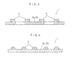
- Fig. 3 and Fig. 4 each is a sectional side view showing an example of the structure of the projection (boss).
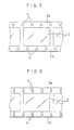
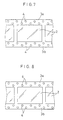
- Fig. 5, Fig. 6, Fig. 7, Fig. 8, Fig. 9, and Fig. 10 each is a plan view showing an example of the disposed pattern of projections.
- Fig. 11 is an enlarged side view illustrating the size of the projection
- Fig. 12 is a side view showing the state of processing a silver halide photographic material for photographing which is preferably applied to the processing method of the present invention.
- the photographic material is swirlingly wound to form a series of continuous gaps adjacent to the surface of the light-sensitive layer between the frontside of the photographic material and the backside of the same photographic material.
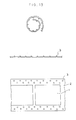
- Fig. 13 illustrate an examples of the silver halide photographic material of the present invention having bosses, wherein the upper figure is a sectional view showing the form of swirlingly winding the silver halide photographic material having bosses, the intermediate figure is a sectional side view showing the form of the bosses of a silver halide photographic material of the present invention, and the lower figure is a plan view of the silver halide photographic material having bosses.
- Fig. 14 shows an example of forming a series of continuous gaps adjacent to the surface of the light-sensitive layer between the frontside of the photographic material and a light-insensitive material.
- the upper figure is a sectional side view showing the form of swirlingly winding the silver halide photographic material together with a dummy film having projections
- the intermediate figure is a sectional side view of the dummy film
- the lower figure is a plan view of the dummy film having projections wherein convex 13 is provided on the frontside of the film and convex 14 is provided on the backside of the film and they are illustrated as ⁇ and > (dotted line), respectively, in the lower figure.
- Fig. 15 is a graph schematically showing the finished performance of processing after 3-month running processing as a function of the processed amount per day.
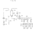
- Fig. 16 is a schematic diagram of a processing apparatus in accordance with the present invention.
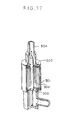
- Fig. 17 is a partially cut slant view showing the inside of a processing container case for roll-form photographic light-sensitive materials in accordance with the present invention.
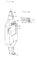
- Fig. 18 is a partially cut slant view showing a processing container for sheet-form photographic light-sensitive materials not accordance with the present invention.
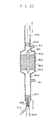
- Fig. 19 is a partially cut slant view showing a processing container for industrial X-ray films not in accordance with the present invention.
- Fig. 20 is a schematic sectional view showing another example of a processor for use in the present invention.
- a characteristic feature of a preferred embodiment of the present invention is that the amount of processing solution employed is reduced and the processing container is made compact by superposing photographic light-sensitive materials (e.g., at least two light-sensitive materials) such that a gap is formed therebetween and adjacent to the surface of the light-sensitive layer of the photographic light-sensitive material to maintain a substantially constant gap width with a substantially fixed state during the processing by supplying a processing solution to the gap to process the light-sensitive material.
- photographic light-sensitive materials e.g., at least two light-sensitive materials
- the gaps can be formed by providing projections at portions excluding image-forming portions and preferably forming periodical projections at both of the margin portions of the photographic light-sensitive material.
- a light-insensitive member such as a light-insensitive film (e.g., a long roll form) having convex portions (projections) at both of the margin portions and a film (e.g., a long roll form) having convex and concave surfaces at both of the margin portions, which forms a gap at the image-forming surface of a photographic light-sensitive material by supporting both of the margin portions of the light-sensitive material with the projections, can be used.
- the light-insensitive member does not involve any elements which contribute for an image (e.g., an emulsion layer).
- the amount of proccessing solution supplied to the gaps can further be reduced.
- the light-sensitive film may be wound in roll form.
- the gap is formed having a width capable of stably supplying a processing solution, and is from 0.05 mm to 2 mm, and particularly preferably from 0.05 mm to 0.5 mm.
- the gap may be formed (1) by providing convex portions (projections) at both the margin portions of one surface side of a photographic light-sensitive material or (2) by inserting a light-insensitive member (a member for forming a gap) between two photographic light-sensitive materials for forming a gap between the member and the emulsion surface of each of the photographic materials.
- Examples of the method (1) include a method of forming bosses at both the margin portions of a photographic light-sensitive material by pressing, heating, etc., and a method of forming waved portions at both the margin portions by pressing, heating, etc.
- the form of the boss may be a polyangular pyramid such as a triangular pyramid, a tetraangular pyramid, etc., a cone, a polyangular prism such as a triangular prism, a column, a wart form, a bowl form, etc.
- the boss has a diameter (D) of from 0.01 mm to 2 mm, a height (H) of from 0.05 mm to 2 mm, and an interval (L) along the photographic material of less than 40 cos -1 ( 20-H / 20) mm.
- Waved portions along both of the margin portions of a film may be formed by heating or pressing.
- the height of the wave may be from the height (H) of the boss to 2H
- the interval of the waves may be from the interval (L) of the bosses to 2L
- size of the wave may be from the interval (L) of the bosses to 2L.
- Examples of the method (2) include a method of forming a gap by superposing a dummy film having convex portions (projections) on both surfaces thereof (at both the margin portions only) to a photographic light-sensitive material and then swirlingly winding the assembly; and a method of using a structural material allowing for the insertion of spacers between two photographic light-sensitive materials for forming a gap along both of the margin portions of each photographic material, which gap is capable of conveying a processing solution.
- the manner of forming the convex portions is the same as the case of forming convex portions of the photographic light-sensitive material as described above.
- the form of the convex portions may be the same as those of the light-sensitive material, or from 2 to 4 times larger than the convex portions of the light-sensitive material in the height.
- the light-sensitive material(s) used in the present invention may take various forms.
- a roll form light-sensitive material In a roll form light-sensitive material, (a) it is swirlingly wound to form a continuous series of gaps (Fig. 17), (b) it is spirally and cylindrically wound to form a continuous series of gaps, or (c) two or more thereof are arranged in parallel or in an arc form with a constant gap width.
- two or more light-sensitive materials may be the same or different as long as the constant gap width is maintained. If two or more light-sensitive materials are used, they may be the same or different as long as the constant gap width is maintained. If different silver halide light-sensitive materials are used, it is necessary that at least 1/2 of the number of the light-sensitive materials has a support thickness of at least 80 ⁇ m.
- the gap is formed by the gap forming ability.
- the thus formed gap has a width of from 0.05 to 2 mm.
- the support has a thickness of 60 ⁇ m or more, the gap formed between the light-sensitive materials or between the light-sensitive material and the light-insensitive member can be kept constantly due to the rigidity of the support. Therefore, if the gap width is over 2mm, it is difficult to maintain the gap, and further, it is also difficult to form a constant gap width of less than 0.05 mm in the case of using a support of 80-200 ⁇ m thickness which is generally used in the art.
- the gap or continuous series of gaps formed adjacent to the light-sensitive layer has a substantially constant width over the entire photographic material and the gap width is maintained substantially constant during the processing.
- substantially means that, for example, the gap width may deviate to some extent where the processing solution is supplied or the gap of a portion apart from the convex portion may deviate to some extent as compared to the vicinity of the means of fixingly forming the gap, e.g., the convex portion.
- the term "some extent" means that in the light-sensitive material in the form of a long roll size, the deviation is preferably within 10L, more preferably within 6L, and particularly preferably within 3L in terms of the interval of the bosses. If the light-sensitive material is subjected to the winding and rewinding alternately within the above range of deviation, undesirable streaks caused by the bosses of the light-sensitive material or the light-insensitive member can be prevented.
- the gap is capable of conveying a processing solution such that the processing solution may be supplied to the gap and then replaced.
- processing by supplying a processing solution means that the processing solution is supplied into the gap by a supply means controlled by an external force.
- the supply means includes, e.g., a pump for applying positive pressure or by suction of the processing solution through the gap, or the combination thereof.
- the processing solution is preferably supplied to the gap by applying positive pressure (pressing) or by suction.
- the pressure at applying or suction varies depending on the capacity of the gaps formed adjacent to the light-sensitive surface of a silver halide photograghic material and the viscosity of the processing solution, but is generally form 0.2 to 20 kg/cm 2 , and preferably form 1 to 6 kg/cm 2 in absolute value.
- a second feature of the present invention is that the processing solution is replaced in an amount equivalent to from 1 to 10 times the capacity of the gaps with processing solution external to the gaps until one step of processing is finished.
- the capacity of the gaps is the total sum of the capacities of each of the gaps formed adjacent to the light-sensitive-surface of the photographic light-sensitive material.
- the replacement volume of the processing solution can be determined by comparing the amount of the processing solution supplied to the spaces forming the gaps by the light-sensitive materials or light-insensitive materials with the total capacities of the gaps.
- the processing solution stream is passed (i.e., introduced and replaced) through each gap adjacent to the light-sensitive layer.
- the amount (volume) of the processing stream passed through the gaps is at least equivalent to the capacity (volume) of the gaps.
- the processing stream is reversed or alternated when passed through each gap during the processing.
- the replacement volume is the amount of processing solution for a processing step that is passed through the gaps.
- An equivalent replacement volume is that volume equal to the capacity (volume) of the gaps.
- One step of processing is a processing step using a distinct processing solution.
- the processing of a black and white photographic light-sensitive material might include a development step, a fix step, a stop step, a stabilization step, a wash step, etc., each of which could employ a distinct process solution.
- the processing of a color photographic light-sensitive material might include a color development step, a fix step, a bleach step, a bleach-fix (blix) step, a reversal step, a stabilization step, a wash step, etc. It is unnecessary to replace a processing solution in an amount of at least an equivalent to the capacity of the gaps in all of the above described processing steps, but it is particularly preferred that in at least one step including a development step, the processing solution is replaced in an amount at least equivalent to the capacity of the gaps.
- the processing solution is replaced in an amount of from one equivalent to 10 equivalents of the capacity of the gaps, and particularly preferably from 1.2 equivalents to 6 equivalents.
- the photographic performance can differ between the right side end and the left side end of the photographic material.
- the exposure amount is large, the tendency is too pronounced to use such processing practically.
- the stream direction of a processing solution is reversed from 3 to 100 times, and particularly preferably from 4 to 10 times during the course of a single processing step.
- the processing solution is replaced.
- a long photographic light-sensitive material is swirlingly wound
- substantially perpendicular means perpendicular within ⁇ 30°.
- the replacement of a processing solution may be in a constant direction during one step of processing but may be reversed (e.g., to the opposite direction) with the passage of time.
- a stop step may be employed at the change of direction. To obtain uniform processing, it is preferred to change the replacement direction with the passage of time.
- a processing solution is forcibly supplied to narrow gaps by a supply means without spontaneously falling of a processing solution.
- good photographic images are unexpectedly obtained using a small amount of processing solution.
- Such excellent results could not have been expected from conventional development processing in a tank system, a system of using Nikor type processor, and a system using a Darkless processor.
- a photographic light-sensitive material is in the stream of a processing solution such that processing is carried out very efficiently. Namely, in accordance with the process of the present invention, a high degree of stirring of the processing solution which has not been obtained using a conventional tank development system is achieved.
- a third feature of the present invention is that a reduced amount of the processing solution is supplied to a photographic light-sensitive material loaded in a processing container to efficiently carry out processing of the light-sensitive material without substantially moving the processing container.
- the photographic light-sensitive material can preferably be processed with a processing solution in an amount of at least two equivalent of the volume capacity of the gaps adjacent to the light-sensitive surface of the light-sensitive material.
- the term "without substantially moving” means that a photographic light-sensitive material loaded in a processing container is not moved, for example, by shaking the container by hand as in a system using a Nikor-type processor.
- stirring in each step of the development processing and particularly the stirring involving micro-vibration by supersonic waves, are rather preferably conducted in the present invention.
- the main stream of the processing solution is preferably not generated by largely shaking or vibrating the processing container.
- a fresh processing solution is efficiently used for processing. It has been found that in the process of the present invention, the processing solution is efficiently used, that is, the amount of the processing solution is reduced. Furthermore, the process of the present invention provides excellent processing stability and a surprising increase in the sensitivity and improved image graininess of a photographic light-sensitive material when the processing solution is a developer.
- FIGs. 16 to 20 Practical examples of the processing container for use in accordance with the process of the present invention are shown in Figs. 16 to 20, but the processing container for use in the present invention is not limited thereto. Details of these containers are described below.
- the processing method of the present invention is preferably applied to a light-sensitive material for photographing or in camera use.
- a light-sensitive material for photographing the following light-sensitive materials (1), (2), and (3) are preferred.
- the projections are alternately disposed in at least two lines.
- the projections at one margin portion and the projections at the other margin portion of the light-sensitive material are disposed symmetrically with one other.
- the above described light-sensitive material for photographing which is well adapted for processing in accordance with the present invention can be processed in a wound state by passing a processing solution in the width direction of the light-sensitive material from one end side portion to the other end side portion.
- the projections formed at both the margin portions of the light-sensitive material for photographing function as a spacer for maintaining constant a gap of the desired width between the adjacent light-sensitive materials in a wound state.
- the processing solution flowing through the gaps is uniformly supplied to the surface of the silver halide emulsion layer of the light-sensitive material for photographing, to thereby prevent uneven processing.
- Fig. 1 is a plan view of a light-sensitive material for photographing which is well adapted for processing in accordance with the present invention
- Fig. 2 is a sectional view taken along the line II-II of Fig. 1.
- the photographic film 1 is in the form of a long roll having latent image portions 2.
- projections 4 are formed along the lengthwise direction of the film 1.
- the cross section of the projection 4 has a round mountain shape.
- the projections 4 are intermittently formed in a periodic interval, preferably the same interval, along the lengthwise direction of the film.
- the projections are formed at the same surface, that is, either the emulsion layer surface or the back surface (base surface) of the film 1.
- the tips of the projections 4 formed at the base surface side are brought into contact with the emulsion layer surface such that even flow of processing solution is facilitated at the emulsion layer surface to prevent the occurrence of uneven processing. Furthermore, when the film 1 is loaded in a camera, the operation is convenient.
- one reason for forming the projections 4 at the emulsion layer side is that it is easy to form such projections.
- projections are formed from deformations of the support of the film 1 itself from the viewpoints of facility of the production and low cost. That is, as shown in Fig. 2, the projections 4 of the film 1 are formed by press molding or press heating molding of the film 1. In this case, the projections are formed preferably after coating the emulsion layer(s) on the support of the film 1. Furthermore, the projections 4 may be formed after photographing the film 1 and before processing the film.
- margin portions 3a and 3b are cut at predetermined positions and having a predetermined size, which projections 4 are then formed by bending the cut.
- a coating composition is applied to the surface of the margin portions of the film 1 to obtain a desired pattern and then solidified to form the projections 4.
- Useful coating agents for forming such projections include hot melt series coating agents such as polyamide, polyester, etc.; room-temperature curing type rubbers such as silicone, etc.; reaction setting type resins such as elastomers, epoxy resins, polyurethane, etc.; thermosetting type resins; ultraviolet ray setting type resins such as polyester acrylate, etc.
- the method of forming the projections 4 is not limited to the above-described methods and, for example, an embossing method, a compressive boring method, an etching method, a soldering method, etc., may also be used.
- composition of the support of the film there is no particular limitation regarding the composition of the support of the film 1.
- Useful support materials include polyester, polyethylene polypropylene, polyimide, polyamide, polyethylene terephthalate (PET), TAC, POM, teflon, ABS resins, and a laminate of two or more of these materials. Of these materials, PET and TAC (triacetyl cellulose) are preferred.
- the support preferably has a thickness of from 0.05 to 1 mm, and particularly preferably from 0.1 to 0.2 mm.
- the height H of the projection 4 shown in Fig. 11 is preferably from about 0.05 to 1 mm, and particularly preferably from about 0.1 to 0.3 mm.
- the height H of the projections 4 sets the gap distance of the gap 7 of the roll 5 described below. If the height H is less than 0.05 mm, it is difficult to pass the processing solution through the gaps, while if the height H is over 1 mm, the selection and working of the film support becomes difficult.
- the diameter D H/2 of the projection 4 at the half height H/2 is preferably from about 0.005 to 8 mm, and particularly preferably from 0.15 to 0.5 mm.
- the strength of the projection is weak such that when the film 1 is wound, the film tends to adhere to itself at adjacent portions, and if D H/2 is over 8 mm, the area of the margin portions 3a and 3b is unnecessarily increased to reduce the area of the image portion 2.
- the ratio of the long diameter to H/2 of the height may be in the range described above.
- the maximum length of the cross section to H/2 of the height may also be in the above described range.
- the mean interval L between each adjacent projections 4 along the lengthwise direction of the film 1 is preferably from about 0.005 to 20 mm, and particularly preferably from about 1 to 10 mm.
- the interval L is less than 0.005 mm, it becomes difficult to pass a processing solution between the adjacent projections and if the interval L is over 20 mm, the film of the portion not supported by the projections 4 is bent in the roll 5 of the film 1 as shown in Fig. 12, such that the gap interval 7 is not kept constant.
- Fig. 12 is a sectional side view of a roll 5 of the film 1.
- an end of film 1 is fixed to a core 6, the film 1 is spirally wound to form a roll 5, which roll 5 is placed in a cartridge or other processing container (not shown), and each of processing solutions such as a developer, a bleach solution, a fix solution, wash water, etc., is passed, in succession, from one side end portion of the roll 5 to the other side end portion thereof.
- processing solutions such as a developer, a bleach solution, a fix solution, wash water, etc.
- the processing solution flows in the width direction (the perpendicular direction of the paper surface of Fig. 12) of the film 1 through the gaps formed between each of the adjacent films 1, such that the processing solution is brought into contact with the surface of the emulsion layer of the film 1 to process the film.
- the processing solution is uniformly supplied to the entire surface of the emulsion layer and uneven processing is prevented.
- Figs. 5 to 10 each is a plan view of a film showing an example of the pattern of the projections 4.
- projections 4 are formed along one line at each of the margin portions 3a and 3b, and the projections at the margin portion 3a and the projections 4 at the margin portion 3b are disposed alternately with each other.
- the patterns of projections 4 shown in Fig. 6, Fig. 7, and Fig. 8 are formed along two lines at each of the margin portions 3a and 3b.
- the reinforcing effect for the projections 4 is increased. Namely, when the film 1 is wound, this reinforcing effect prevents the collapse of the projections 4 and the bending of the film 1 such that contact of the emulsion layer surface with the base surface is prevented. In particular, when the film 1 of the roll 5 is wound tightly, the above-described problem does not occur and the gaps 7 are kept constant.
- the projections 4 formed along four lines at the margin portions 3a and 3b are disposed in the same width direction of the film.
- the projections 4 may be disposed alternately at the margin portion 3a and the margin portion 3b as shown in Fig. 5.
- the projections 4 formed along two lines at each margin portion are disposed alternately, and the projections 4 of the same pattern are formed at the other margin portion (margin b).
- the pattern of the projections 4 formed at the margin portion 3a is same as the above-description construction in Fig. 7, but the pattern of the projections 4 formed at the margin portion 3b is symmetrical with the projection pattern at the margin 3a to the center line in the lengthwise direction of the film 1.
- the stream of the processing solution is further dispersed such that the effect of preventing uneven processing is enhanced as compared with the construction shown in Fig. 6.
- the pattern of the projections 4 at the margin portion 3a is symmetrical with the pattern of the projections 4 at the margin portion 3b, uneven processing tends not to occur regardless of the direction of flow of the processing solution (i.e., from the margin portion 3a side or the margin portion 3b side), such that the subject construction is suitable for processing a light-sensitive materials by changing the flow direction of the processing solution in a series of processing steps.
- the projections 4 shown in Fig. 9 and Fig. 10 exemplify a cross section of the projection 4 other than a circle. That is, the cross section of the projection 4 shown in Fig. 9 is an ellipse wherein the long axis thereof is in the width direction of the film 1 and the cross section of the projection 4 shown in Fig. 10 is an ellipse wherein the long axis is in the lengthwise direction of the film 1.
- the construction shown in Fig. 9 is useful for preventing adjacent films from approaching or contacting each other by above-described bending of the film. Also, the construction shown in Fig. 10 is useful for dispersing the stream of the processing solution to a high degree.
- the form of the cross section of the projection 4 is not limited to a circle and ellipse, but may take other forms such as a triangle, a square, or other polygons.
- two or more kinds of projections each having a different sectional form may he formed on the same film.
- the pattern of the projections 4 are not limited to those shown in Fig. 1 and Figs. 5 to 10.
- the pattern of the projections may be appropriately combined, projections may be irregularly disposed, or the projections may have a construction other than described above.
- the film 1 shown in each figure does not have perforations; however, in the present invention, the film may have or may not have perforations.
- the projections 4 can be utilized as a means for winding the film 1.
- the light-sensitive material for photographing for use in the present invention comprises a support composed of PET, TAC, etc., as described above having thereon at least one light-sensitive silver halide emulsion layer on one surface of the support.
- an antihalation layer may be formed on the emulsion layer side or the opposite side of the support, and when the light-sensitive material comprises two or more silver halide emulsion layers each having a different light sensitivity, an interlayer can be formed between them, and one or more protective layer(s) may be formed on the surface of the uppermost emulsion layer.
- light-sensitive material for photographing which can be processed in accordance with the present invention
- light-sensitive materials include color negative photographic films, color reversal photographic films, color positive photographic films, black and white photographic films, micro films, motion picture films, etc.
- the size of the photographic film for processing in accordance with the present invention which films include those of 135 mm size, and 110 mm size, etc., as well as other sizes.
- a light-sensitive material for photographing such as a photographic light-sensitive film
- a processing solution is uniformly supplied to the surface of the emulsion layer of the film such that uneven processing is prevented.
- the volume of the processing container is from 200 ml to 3000 ml, preferably from 300 ml to 1500 ml, and more preferably from 300 ml to 800 ml per unit area (1 square meter) of the light-sensitive material being processed.
- the process of the present invention by using such a small processing container, good photographic images with high sensitivity and gamma are obtained.
- the process of the present invention provides excellent uniformity of processing, reproducibility, and a smaller difference in photographic performance is observed in the lengthwise direction of the processed film as compared to the case of using, for example, the Darkless processor kit, made by Fuji Photo Film., Co.
- the photographic light-sensitive material can be processed by using a very compact processing container having a volume of from 5 ml to 100 ml, and preferably from 8 ml to 60 ml.
- a columnar processing container which can contain a long roll photographic light-sensitive material in a swirlingly wound form is preferred.
- a cartridge can be used as the processing container.
- a cartridge containing the photographic light-sensitive film of the present invention i.e., a roll film with gaps between adjacent films
- the film is rewound in the same cartridge and is then unloaded from the camera and used for processing by passing each processing solution through the roll film in the cartridge.
- an ordinary cartridge containing the photographic light-sensitive film of the present invention is loaded in a camera. After imagewise exposing the photographic film, the photographic film once rewound in the cartridge is wound in the dark in a processing container for use in the present invention in the dark, and the film is then processed in the processing container as described above.
- the processing container for use in the present invention may be equipped with a pressing or holding member for the film roll, a passageway for the film, and a turning sendback means for spooling.
- the amount of each processing solution per unit area of the photographic light-sensitive material being processed is greatly reduced.
- the light-sensitive material can be processed by a small amount of each processing solution of from 300 to 1500 ml, and particularly from about 300 to 800 ml per square meter.
- the amount required for processing is from 300 to 800 ml; in the case of a bleach solution, the amount is from 200 to 500 ml; in the case of a fix solution, the amount is from 300 to 800 ml; and in the case of wash water or a stabilization solution, the amount is from 300 to 1500 ml per square meter of the light-sensitive material being processed.
- each processing solution Since in the processing method of the present invention the amount of each processing solution is relatively small, the waste solution can be discharged without causing excessive environmental pollution. Also, each processing solution is more easily formulated and it becomes unnecessary to consider deviation in photographic performance due to the fatigue of the processing solution. Furthermore, the management of processing is greatly simplified. Accordingly, the design of an automatic processor is likewise simplified and maintenance of the processor is facilitated.
- silver bromide, silver iodobromide, silver iodochlorobromide, silver chlorobromide, or silver chloride may be used as the silver halide.
- the mean grain size of the silver halide grains (when the grains are sphere or near sphere, the mean grain size is the diameter of the grain and when the grains are cubic grains, the grain size is the side length and the mean grain size is shown by the mean value based on the projected area of the grains) constituting the photographic silver halide emulsion for use in the present invention is not particularly limited, and the grain size distribution may be narrow or broad.
- the silver halide grains constituting the at least one photographic emulsion layer of the light-sensitive material of the present invention may have a regular crystal form such as a cubic form and an octahedral form, an irregular crystal form such as a sphere, a tabular form, etc., or a composite form of these crystal forms.
- the silver halide grains may be composed of a different phase between the inside and the surface portion thereof or may be composed of a homogeneous phase.
- the silver halide grains may be of the type which forms a latent image mainly on the surface of the grains or of the type which forms a latent image mainly in the inside of the grains.
- the photographic silver halide emulsions for use in the present invention can be prepared using the methods described in P. Glafkides, Chimie et Physique Photographique , published by Paul Montel, 1967, G.F. Duffin, Photographic Emulsion Chemistry , published by the Focal Press, 1966, V.L. Zelikman et al, Making and Coating Photographic Emulsion , published by the Focal Press, 1964, etc.
- an acid method a neutral method, an ammonia method, etc.
- a method of reacting a soluble silver salt and a soluble halide a single jet method, a double jet method, or a combination of these methods can be used.
- a cadmium salt, a zinc salt, a thallium salt, an iridium salt or a complex salt thereof, a rhodium salt or a complex salt thereof, an iron salt or a complex salt thereof, etc. may be present in the system.
- the silver halide emulsion for use in the present invention may be chemically sensitized.
- the methods described, e.g., in H. Frieser, Die Unen der Photogaphischen mit Silberhalogeniden , pages 675 to 734, published by Akademische Verlagsgesellschaft, 1968 can be used.
- a sulfur sensitizing method using active gelatin and a sulfur containing compound which reacts with silver e.g., thiosulfates, thioureas, mercapto compounds, and rhodanines
- a reduction sensitizing method using a reducing material e.g., stannous salts, amines, hydrazine derivatives, formamidinesulfinic acid, and silane compounds
- a noble metal sensitizing method using a noble metal compound e.g., gold complex salts and complex salts of metals belonging to group VIII of the periodic table, such as Pt, Ir, Pd, etc.
- a combination of these chemical sensitizing agents can be used.
- the photographic silver halide emulsion for use in the present invention can contain various compounds for preventing the occurrence of fog during the production, storage, or photographic processing of the photographic light-sensitive material, or for stabilizing the photographic performance thereof.
- antifoggants or stabilizers such as azoles [e.g., benzothiazolium salts, nitroimidazoles, nitrobenzimidazoles, chlorobenzimidazoles, bromobenzimidazoles, mercaptothiazoles, mercaptobenzothiazoles, mercaptobenzimidazoles, mercaptothiadiazoles, aminotriazoles, benzotriazoles, nitrobenzotriazoles, and mercaptotetrazoles (in particular, 1-phenyl-5-mercaptotetrazole)]; mercaptopyrimidines; mercaptotriazines; thioketo compounds (e.g., oxazolinethione); azaindenes [e.g., triazaindenes, tetraazaindenes (in particular, 4-hydroxy-substituted (1,3,3a,7)tetraazaindenes), pent
- azoles e.
- gelatin is advantageously used but other hydrophilic colloids can be also used.
- proteins such as gelatin derivatives, graft polymers of gelatin and other polymers, albumin, casein, etc.; cellulose derivatives such as hydroxyethyl cellulose, carboxymethyl cellulose, cellulose sulfuric acid ester, etc.; saccharose derivatives such as sodium alginate, starch derivatives, etc.; and synthetic hydrophilic polymers (e.g., homopolymers and copolymers such as polyvinyl alcohol, polyvinyl alcohol partial acetal, poly-N-vinylpyrrolidone, polyacrylic acid, polymethacrylic acid, polyacrylamide, polyvinyl imidazole, polyvinyl pyrazole, etc.) can be used as the binder or protective colloid.
- synthetic hydrophilic polymers e.g., homopolymers and copolymers such as polyvinyl alcohol, polyvinyl alcohol partial acetal, poly-N-vinylpyrrolidone, polyacrylic acid, polymethacrylic acid, polyacrylamide,
- the photographic silver halide emulsion for use in the present invention may be spectrally sensitized by methine dyes, etc.
- Useful dyes for the spectral sensitization include cyanine dyes, merocyanine dyes, complex cyanine dyes, complex merocyanine dyes, holopolar cyanine dyes, hemicyanine dyes, styryl dyes, and hemioxonol dyes.
- Particularly useful dyes include the dyes belonging to the class of cyanine dyes, merocyanine dyes, and complex merocyanine dyes.
- the above described dyes can have a structure comprising a basic heterocyclic ring nucleus generally utilized for cyanine dyes.
- nuclei include a pyrroline nucleus, an oxazoline nucleus, a thiazoline nucleus, a pyrrole nucleus, an oxazole nucleus, a thiazole nucleus, a selenazole nucleus, an imidazole nucleus, a tetrazole nucleus, a pyridine nucleus, etc.; nuclei formed by fusing an aliphatic hydrocarbon ring to the above-described nuclei, and nuclei formed by fusing an aromatic hydrocarbon ring to the above-described nuclei, such as an indolenine nucleus, a benzindolenine nucleus, an indole nucleus, a benzoxazole nucleus, an naphthoxazole nucleus,
- a 5-or 6-membered heterocyclic nucleus such as a pyrazolin-5-one nucleus, a thiohydantoin nucleus, a 2-thiooxazolin-2,4-dione nucleus, a rhodanine nucleus, a thiobarbituric acid nucleus, etc.
- a nucleus having a ketomethylene structure can be employed as a nucleus having a ketomethylene structure.
- the sensitizing dyes may be used alone or in combination thereof.
- a combination of sensitizing dyes is frequently used for the purpose of super color sensitization.
- the photographic silver halide emulsion may further contain a dye which does not provide a spectral sensitizing action by itself, or a substance which does not substantially absorb visible light but provides a super color sensitization effect when used together with a sensitizing dye.
- the photographic silver halide emulsion layer of the photographic light-sensitive material of the present invention may contain a color forming coupler, namely, compounds which form color by oxidative coupling with an aromatic primary amine developing agent (e.g., phenylenediamine derivatives, aminophenol derivatives, etc.) in color development processing.
- a color forming coupler namely, compounds which form color by oxidative coupling with an aromatic primary amine developing agent (e.g., phenylenediamine derivatives, aminophenol derivatives, etc.) in color development processing.
- useful magenta couplers include 5-pyrazolone couplers, pyrazolobenzimidazole couplers, cyanoacetyl coumarone couplers, open chain acylacetonitrile couplers, etc.; useful yellow couplers include acylacetamide couplers (e.g., benzoylacetanilides and pivaloylacetanilides), etc.; and useful cyan couplers include naphthol couplers, phenol couplers, etc.
- couplers are desirably non-diffusible couplers each having a hydrophobic group called as a ballast group in the molecule.
- the couplers may be four-equivalent or two-equivalent to silver ion.
- the silver halide emulsion layer may contain a colored coupler having a color correction effect or a DIR coupler, i.e., a coupler which releases a development inhibitor upon development.
- the emulsion layer may contain a non-coloring DIR coupling compound which provides a colorless product by a coupling reaction, and releases a development inhibitor in place of the DIR coupler.
- a high-boiling organic solvent such as a phthalic acid alkyl ester (e.g., dibutyl phthalate and dioctyl phthalate), phosphoric acid ester (e.g., diphenyl phosphate, triphenyl phosphate, tricresyl phosphate, and dioctylbutyl phosphate), citric acid ester (e.g., tributyl acetylcitrate), benzoic acid ester (e.g., octyl benzoate), alkylamides (e.g., diethyl laurylamide), fatty acid ester (e.g., dibutoxyethyl succinate and dioctyl azelate), trimesic acid ester (e.g., tributyl trimesate), etc., or a low boiling organic acid having a boiling point of from about 30°C to 150
- a mixture of the high-boiling organic solvents and the low-boiling organic solvents may be used.
- the photographic silver halide emulsion layers and other hydrophilic colloid layers of the photographic light-sensitive material of the present invention may contain an inorganic or organic hardening agent.
- the useful hardening agents include chromium salts (e.g., chromium alum and chromium acetate), aldehydes (e.g., formaldehyde, glyoxal, and glutaraldehyde), N-methylol series compounds (e.g., dimethylol urea and methyloldimethyl hydantoin), dioxane derivatives (e.g., 2,3-dihydroxydioxane), active vinyl compounds (e.g., 1,3,5-triacryloylhexahydro-s-triazine-and 1,3-vinylsulfonyl-2-propanol), active halogen compounds (e.g., 2,4-dichloro-6-hydroxy-1,3,5-triazine),
- the photographic silver halide emulsion layer and other hydrophilic colloid layers of the photographic light-sensitive material of the present invention may further contain various surface active agents for use, e.g., as a coating aid, for static prevention, slidability improvement, improvement of dispersion by emulsification, to prevent sticking, and improvement of photographic characteristics (e.g., development acceleration, and increase in contrast and sensitivity).
- various surface active agents for use e.g., as a coating aid, for static prevention, slidability improvement, improvement of dispersion by emulsification, to prevent sticking, and improvement of photographic characteristics (e.g., development acceleration, and increase in contrast and sensitivity).
- the silver halide photographic emulsion for use in the present invention may contain other additives including, e.g., whitening agents, dyes, spectral sensitizers, desensitizers, hardening agents, coating aids, antistatic agents, plasticizers, lubricants, matting agents, development accelerators, oils, mordants, ultraviolet absorbents, fading inhibitors, and color fog inhibitors.
- additives including, e.g., whitening agents, dyes, spectral sensitizers, desensitizers, hardening agents, coating aids, antistatic agents, plasticizers, lubricants, matting agents, development accelerators, oils, mordants, ultraviolet absorbents, fading inhibitors, and color fog inhibitors.
- the photographic silver halide emulsion layer and other layers of the photographic light-sensitive material of the present invention are coated on a flexible support such as a plastic film or papers generally employed for a photographic light-sensitive material.
- Useful flexible supports include films composed of semi-synthetic or synthetic polymers such as cellulose nitrate, cellulose acetate, cellulose acetate butyrate, polystyrene, polyvinyl chloride, polyethylene terephthalate, polycarbonate, etc., and papers laminated with a baryta layer or an ⁇ -olefin polymer (e.g., polyethylene, polypropylene, and an ethylene/butene copolymer). Further, supports as described in U.S. Patent 4,954,838 can also be used in the present invention.
- the photographic silver halide emulsion layers and other hydrophilic colloid layers are coated onto the support or onto previously coated layers by various known coating methods.
- useful coating methods include a dip coating method, a roller coating method, a curtain coating method, an extrusion coating method, a bead coating method, etc.
- the coating methods described in U.S. Patents 2,681,294, 2,761,791, and 3,526,528 can be advantageously used.
- the present invention can be applied to a multilayer multicolor natural color photographic light-sensitive material having at least two silver halide emulsion layers each having a different spectral sensitivity on a support.
- a multilayer natural color photographic light-sensitive material generally has at least one red-sensitive emulsion layer, at least one green-sensitive emulsion layer, and at least one blue-sensitive emulsion layer on a support.
- the disposition order of these emulsion layers is selected depending on the particular application.
- the red-sensitive emulsion layer generally contains a cyan-forming coupler
- the green-sensitive emulsion layer generally contains a magenta-forming coupler
- the blue-sensitive emulsion layer generally contains a yellow-forming coupler but different combinations of couplers can also be employed.
- the photographic light-sensitive material adaptable for processing in accordance with the present invention includes various kinds of color and black and white light-sensitive materials.
- the present invention can be applied to color negative photographic films for photographing (general color negative films and motion picture films), color reversal photographic films (for slide, for motion picture, or as the case may be, containing no couplers), color photographic papers, color positive photographic films (for motion picture, etc.), color reversal photographic papers, color photographic light-sensitive materials utilizing a silver dye bleach image forming process, photographic light-sensitive materials for making printing plates (lithographic light-sensitive films, scanner films, etc.), radiographic light-sensitive materials (direct and indirect medical X-ray films, industrial X-ray films, etc.), black and white negative photographic films for photographing, black and white photographic papers, photographic light-sensitive micro films (for COM, micro films, etc.), etc.
- the effects of the present invention are most pronounced when applied to a light-sensitive material for photographing.
- the photographic light-sensitive material of the present invention is a color photographic material for photographing
- the film swelling rate T1 ⁇ 2 is 30 seconds or less.
- the thickness is preferably not more than 25 ⁇ m and has T1 ⁇ 2 of preferably 20 seconds or less measured at 25°C and a relative humidity of 55% (2 days).
- the film swelling rate T1 ⁇ 2 can be measured according to methods well known in the art. For example, the film swelling rate can be measured by using a swellometer of the type described in A. Green et al, Photographic Science and Engineering, Vol. 19, No. 2, pages 124-129.
- the film swelling rate T1 ⁇ 2 can be adjusted by adding a hardening agent to gelatin used as a binder, or by changing the condition (e.g., humidity and temperature) with the passage of time after coating the layers.
- the swelling ratio is preferably from 150 to 400%.
- the swelling ratio is calculated according to the formula (A-B)/B
- processing temperature is usually selected in the range of from 18°C to 50°C, but the temperature may be lower than 18°C or higher than 50°C depending on the particular application
- the present invention can be applied to black and white photographic processing, i.e., photographic processing for forming silver images or color photographic processing for forming color images.
- the processing process of the present invention can be used for all the processing steps of photographic processing, or for one step or two or more steps of the photographic processing sequence.
- developing agents such as dihydroxybenzenes (e.g., hydroquinone), 3-pyrazolidones (e.g., 1-phenyl-3-pyrazolidone), aminophenols (e.g., N-methyl-p-aminophenol), etc., can be used alone or as a combination thereof.
- dihydroxybenzenes e.g., hydroquinone
- 3-pyrazolidones e.g., 1-phenyl-3-pyrazolidone
- aminophenols e.g., N-methyl-p-aminophenol
- the color developer for processing the color photographic light-sensitive material of the present invention is preferably an alkaline aqueous solution of an aromatic primary amine color developing agent as the main component.
- an aromatic primary amine color developing agent aminophenol series compounds are useful but p-phenylenediamine series compounds are preferably used.
- Typical examples thereof include 3-methyl-4-amino-N,N-diethylaniline, 3-methyl-4-amino-N-ethyl-N- ⁇ -hydroxyethylaniline, 3-methyl-4-amino-N-ethyl-N- ⁇ -methanesulfonamidoethylaniline, 3-methyl-4-amino-N-ethyl-N- ⁇ -methoxyethylaniline, and the sulfates, hydrochlorides, or p-toluenesulfonates of these compounds. Two or more kinds of these compounds may be used depending on the intended application.
- the color developer generally further contains a pH buffer such as a carbonate, borate and phosphate of an alkali metal, and a development inhibitor or an antifoggant such as a bromide, iodide, benzimidazole, benzothiazole, mercapto compound, etc.
- a pH buffer such as a carbonate, borate and phosphate of an alkali metal
- a development inhibitor or an antifoggant such as a bromide, iodide, benzimidazole, benzothiazole, mercapto compound, etc.
- the color developer may further contain a preservative such as hydroxylamine, diethylhydroxylamine, hydrazine sulfites, phenylsemicarbazides, triethanolamine, catecholsulfonic acids, triethylenediamine(1,4-diazabicyclo[2,2,2]octane), etc.; an organic solvents such as ethylene glycol, diethylene glycol, etc.; a development accelerator such as benzyl alcohol, polyethylene glycol, quaternary ammonium salts, amines, etc.; a dye-forming coupler; a competing coupler; a fogging agent such as sodium boron hydride, etc.; an auxiliary developing agent such as 1-phenyl-3-pyrazolidone, etc.; a tackifier; a chelating agent such as an aminopolycarboxylic acid, an aminopolyphosphonic acid, an alkylphosphonic acid, a phosphonocarboxylic acid, etc.
- black and white developing agents such as dihydroxybenzenes (e.g., hydroquinone), 3-pyrazolidones (e.g., 1-phenyl-3-pyrazolidone), and aminophenols (e.g., N-methyl-p-aminophenol) can be used alone or in combination thereof.
- the pH of the color developer and black and white developer is generally from 9 to 12.
- the developer can contain a pH buffer such as a sulfite, carbonate, borate, and phosphate of an alkali metal and a development inhibitor or an antifoggant such as a bromide, iodide, and organic antifoggant.
- a pH buffer such as a sulfite, carbonate, borate, and phosphate of an alkali metal
- a development inhibitor or an antifoggant such as a bromide, iodide, and organic antifoggant.
- the developer may further contain a hard water softener, a preservative such as hydroxylamine, etc., an organic solvent such as benzyl alcohol, diethylene glycol, etc., a development accelerator such as polyethylene glycol, quaternary ammonium salts, amines, etc., a dye-forming coupler, a competing coupler, a fogging agent such as sodium boron hydride, etc., an auxiliary developing agent such as 1-phenyl-3-pyrazolidone, etc., a tackifier, the polycarboxylic acid series chelating agents described in U.S. Patent 4,083,723, and the antioxidants described in West German Patent Publication (OLS) 2,622,950.
- a hard water softener such as hydroxylamine, etc.
- a preservative such as hydroxylamine, etc.
- an organic solvent such as benzyl alcohol, diethylene glycol, etc.
- a development accelerator such as polyethylene glycol, quaternary ammonium salt
- the photographic silver halide emulsion layers are generally bleached.
- the bleach process may be carried out simultaneously with a fix process (bleach-fix process or blix process), or may be carried out separately from the fix process.
- the blix process may be carried out after the bleach process.
- the blix may be carried out using two baths continuously, a fix process may be carried out before the blix process, or a bleach process may be carried out after the blix process.
- bleaching agent compounds of polyvalent metals such as iron(III), cobalt(III), chromium(VI), copper(II), etc., peroxides, quinones, nitro compounds, etc.
- Typical examples of the bleaching agent include ferricyanides; bichromates; organic complex salts of iron(III) or cobalt(III), such as the complex salts thereof of aminopolycarboxylic acids such as ethylenediaminetetraacetic acid, diethylenetriaminepentaacetic acid, cyclohexanediaminetetraacetic acid, methyliminodiacetic acid, 1,3-diaminopropanetetraacetic acid, glycol ether diaminetetraacetic acid, etc., or citric acid, tartaric acid, malic acid, etc.; persulfates; bromates; permanganates; and nitrobenzenes.
- aminopolycaroxylic acid iron(III) complex salts such as ethylenediaminetetraacetic acid iron(III) complex salt, etc., and persulfates are preferred for rapid processing and environmental considerations. Furthermore, the aminopolycarboxylic acid iron(III) complex salt is particularly useful as a bleach solution and a blix solution.
- the pH of the bleach solution or blix solution containing an aminopolycarboxylic acid iron(III) complex salt is usually from 5.5 to 8, but the solution may have a lower pH for rapid processing.
- the bleach solution, the blix solution and the prebath thereof may contain, if necessary, a bleach accelerator.
- Examples of the useful bleach accelerator are compounds having a mercapto group or a disulfide group as described in U.S. Patent 3,893,858, West German Patent 1,290,812, JP-A-53-95630, Research Disclosure , No. 17129 (July, 1978); thiazolidine derivatives described in JP-A-50-140129; thiourea derivatives described in U.S. Patent 3,706,561; iodides described in JP-A-58-16235; polyoxyethylene compounds described in West German Patent 2,748,430; polyamine compounds described in JP-B-45-8836; and bromide ion.
- the compounds having a mercapto group or a disulfido group are preferred for providing a large acceleration effect and in particular, the compounds described in U.S. Patent 3,893,858, West German Patent 1,290,812, and JP-A-53-95630 are preferred. Furthermore, the compounds described in U.S. Patent 4,552,834 are also preferred.
- the bleach accelerator may be incorporated in the photographic light-sensitive material.
- a color photographic light-sensitive material for photographing is blixed, the use of a bleach accelerator is particularly effective.
- Useful fixing agents include thiosulfates, thiocyanates, thioether series compounds, thioureas, a large quantity of iodide, etc., but a thiosulfate is generally used and, in particular, ammonium thiosulfate is most widely used.
- sulfites As a preservative for the blix solution, sulfites, hydrogensulfites, sulfinic acids, or carbonyl-hydrogensulfite addition products are preferably used.
- the silver halide color photographic material of the present invention is generally washed and/or stabilized after desilvering.
- the method of reducing calcium ion and magnesium ion in the wash water as described in JP-A-62-288838 is effectively used.
- the pH of the wash water for processing the photographic light-sensitive material is from 4 to 9, and preferably from 5 to 8.
- the temperature and the time for the wash step is selected according to the characteristics and use of the photographic light-sensitive material, but are generally from 20 seconds to 10 minutes at a temperature of from 45°C to 15°C, and preferably from 30 seconds to 5 minutes at a temperature of from 40°C to 25°C.
- the photographic light-sensitive material of the present invention can be directly processed with a stabilization solution in place of the wash water described above.
- a stabilization solution in place of the wash water described above.
- the known methods described in JP-A-57-8543, JP-A-58-14834, and JP-A-60-220345 can be used.
- the stabilization bath may contain formalin and a surface active agent for use as the final bath for the color photographic light-sensitive material for photographing.
- the stabilization bath can also contain a chelating agent and an antifungal agent.
- the overflow liquid from replenishment of the wash water and/or the stabilization solution as described above can be utilized again in the desilvering step, etc.
- the silver halide color photographic material of the present invention may contain a color developing agent for simplifying and accelerating processing.
- a color developing agent for simplifying and accelerating processing.
- a precursor of the color developing agent for incorporating a color developing agent in the light-sensitive material, it is preferred to use a precursor of the color developing agent.
- examples thereof are the indoaniline series compounds described in U.S. Patent 3,342,597, Shiff base type compound described in U.S. Patent 3,342,599 and Research Disclosure , No. 14850, and ibid. , No. 15159, aldol compounds described in Research Disclosure , No. 13924, metal complexes described in U.S. Patent 3,719,492, and urethane series compounds described in JP-A-53-135628.
- the silver halide color photographic material of the present invention may, if necessary, contain various kinds of 1-phenyl-3-pyrazolidones for the purpose of accelerating the color development. Typical examples of such compounds are described in JP-A-56-64339, JP-A-57-144547, and JP-A-58-115438.
- the various processing solutions in the processing process of the present invention are used at a temperature of from 10°C to 50°C.
- a standard temperature of the processing solution is generally from 33°C to 38°C, but a higher temperature may be employed for accelerating processing to shorten the processing time, or a lower temperature may be employed for improving the image quality and improving the stability of the processing solutions.
- the amount of the processing solution used is greatly reduced. Furthermore, stable photographic performance and good performance is obtained.
- a color negative photographic film (Sample 1) was prepared according to the method described in Example 5 of JP-A-63-70857. The film was cut to 35 mm in width and 1 meter in length, and bosses were formed at both the margin portions along two lines each with the emulsion layer as the upper surface using a knurl roller (rotary embossing means for kimono dressmaking) as shown in Fig. 13 without forming perforations.
- a knurl roller rotary embossing means for kimono dressmaking
- the photographic film was swirlingly wound.
- the cross sectional view of the wound state and the cross sectional view of the film in a plane state are also shown in Fig. 13 together with the plan view of the film.
- projections 3 were formed in a straight line on the photographic film 2 at other portions than image portions 1, that is, at both of the margin portions.
- a dummy film (spacer) 12 shown in Fig. 14 having projections 13 and 14 at both the margin portions can be inserted (or wound together with) the light-sensitive film 11 to form gaps as shown in Fig. 14.
- the cross sectional view of the swirlingly wound photographic film 11 having inserted therebetween the dummy film or spacer 12 and the cross sectional view of the dummy film 12 are shown in Fig. 14 together with a plan view of the dummy film 12 having projections 13 and 14 at both surface sides of the film.
- each boss was 0.5 mm and 0.17 mm, respectively, and the bosses were formed with an interval of 2 mm.
- the bosses in a first margin line were formed at a distance of 1.5 mm from each edge of the film and the bosses in a second line were formed at a distance of 3.5 mm from each edge of the film.
- the film was packed in a processing container shown in Fig. 17 and then processed by the processing steps using the processing solutions described below.
- the volume of each processing solution in the processing container was about 10 ml and the volume of the processing solution in the pipes was about 1.5 ml.
- Processing step Processing Time Processing Temperature Color Development 3' 15" 38°C Bleach 1' 00" 38°C Blix 3' 15" 38°C Wash 1' 40" 35°C Stabilization 40" 35°C Color Developer
- Diethylenetriamine pentaacetic acid 1.0 g 1-Hydroxyethylidene-1,1-diphosphonic acid 2.0 g Sodium sulfite 4.0 g Potassium carbonate 30.0 g Potassium bromide 1.4 g Potassium iodide 1.3 mg Hydroxylamine 2.4 g 4-(N-ethyl-N- ⁇ -hydroxyethylamino)-2-methyl aniline sulfate 4.5 g Water to make 1 liter pH 10.00 Bleach-fix solution Ammonium bromide 50.0 g Ammonium ethylenediaminetetraacetic acid iron (III) 50.0 g Ethylenediaminetetraacetic acid disodium salt 5.0 g Ammonium n
- the processing apparatus shown in Fig. 16 and the processing container shown in Fig. 17 were used, and the light-sensitive material in the processing container was processed while moving about 20 ml of the processing solution upward and downward each time per 15 seconds. This state is explained using Fig. 16 and Fig. 17.
- the imagewise exposed light-sensitive material 502 is swirlingly wound around axis 503 by attaching the end of the light-sensitive material 502 to the axis 503.
- the processing container case 501 is held by frames 505 such that the light-sensitive material 502 is immobile and a pipe for supplying a processing solution is connected to a coupler (coupling means) 504.
- the container case 501 and the coupler 504 in Fig. 17 correspond to a container case 401 and a coupler 402 in Fig. 16, respectively.
- Fig. 16 is a schematic view of a processing system in accordance with the present invention.
- the container case 501 shown in Fig. 17 is coupled with each of processing solutions (413a, 413b, and 413c derived from 413) and the drying portions (409, 410, and 411) in Fig. 16 by means of the coupler 504 in Fig. 17.
- a container case 401 containing an imagewise exposed swirlingly wound light-sensitive material is connected to a 1st processing solution 413a by a coupler 402, change-over valves 403 and 404, and a liquid supply pump 405 through a pipe 406 to fill the container with the 1st processing solution 413a.
- a processing pump 414 While heating the solution with a heater 416, a processing pump 414 is operated in a first direction to send the processing solution to the container and then reversely operated to move the processing solution in the opposite direction to process the light-sensitive material in the container. After processing, a waste liquid discharging cock 415 is opened to discharge the processing solution in the container case 401.
- the light-sensitive material in the container 401 is successively processed with a 2nd processing solution 413b and then a 3rd processing solution 413c, etc.
- Each processing solution is stored in a tank 407 in a manner such that the solution is negligibly deteriorated with the passage of time by means of a floating lid 408.
- the coupler 402 is changed to a coupler 417 for drying mode (409, 410, 411, and 412). Namely, open air is dehumidified by a desiccator 411 and while heating by a heater 409, the hot, dehumidified air is sent to the container case 401 by means of a blower 410 and discharged through a duct 412.
- Fig. 17 is slant view showing the inside of the container 501.
- the container 501 is a container for processing and drying the light-sensitive material 502.
- the container 501 is packed the light-sensitive material 502 in a wound state with a constant gap between the adjacent films.
- the coupler 504 is for connecting the container to each processing solution and a drying system.
- the light-sensitive material 502 is wound around a central axis 503, which is disposed at the center of the processing container case 501.
- the light-sensitive material 502 is embossed at both the margin portions to form gaps when the light-sensitive material is wound, or if the light-sensitive material 502 has no bosses, gaps are formed by using a dummy film or spacer having bosses as described above.
- the frames 505 hold the light-sensitive material 502 in place such that the light-sensitive material does not move up and down vigorously during processing and drying.
- the processing solution is automatically discharged by air pressure after processing and then a next processing solution is supplied to the container for processing.
- the coupler 504 is exchanged and dehumidified air is passed through the processing container at 3.5 liters/min while changing the flowing direction of air once every 15 seconds. After about 2 minutes of drying, the photographic film is removed from the container and when each image formed is printed on a color paper by a conventional color printer, good prints having excellent quality images in sensitivity and gamma without the increase of fog or stain are obtained.
- each of the color developer, the blix solution, and fix solution stock tanks 407 in Fig. 16 was protected from exposure to the ambient air by a floating lid.
- the finished photographic performance was unchanged as shown in Fig. 15.
- the present invention provides stable finished performance independent of the processing amount per day as shown in Fig. 15.
- stable photographic performance is obtained.
- the amount supplied for developing one light-sensitive material is reduced from 45 ml to 25 ml, which results in reduced cost as well as the amount of the waste solution.
- the present invention provides both a stable processed finish and the amount of waste solution is about 1/20 that of the Nikor system.
- Imagewise exposed black and white films i.e., the Sample 1 (light-sensitive material) of Example 1 of JP-A-1-106050, were processed using the processing system shown in Fig. 16.
- the sample film was developed for 4 minutes and 15 seconds at 20°C with Super Prodol (SPD) (developer, made by Fuji Photo Film Co., Ltd.), and then processed for 4 minutes and 15 seconds at 20°C with Super Fuji Fix (fix solution, made by Fuji Photo Film Co., Ltd.), and further processed for 4 minutes and 15 seconds with wash water.
- SPD Super Prodol
- Fuji Color Super HG 400 120 size film (made by Fuji Photo Film Co., Ltd.) was cut in 35 mm width, embossed as in Example 1, and after imagewise exposure was processed by the processing system shown in Fig. 16 as in Example 1 using Mini-labo processing agent CN-16Q for color negative film, made by Fuji Photo Film Co., Ltd. Beautiful color prints having clear colors were thus obtained.
- the processor of Fig. 16 is a small-sized apparatus, it can be transported to a photographing location by car, and the imagewise exposed photographic film can be processed at the photographic location as well as unevenness of processing as in the round tank development was less.
- Example 1 of JP-A-1-93737 The light-sensitive material in Example 1 of JP-A-1-93737 was cut into dental X-ray films (30 mm ⁇ 40 mm, 4 corners were roundly cut). After a dental X-ray exposure of the light-sensitive material, the margin portions of each film were embossed (diameter 0.5 mm, height 0.2 mm, interval 3 mm).
- the films were both developed and fixed using the container of Fig. 18 and the processing system of Fig. 16 using the processing solutions of Example 1 of JP-A-1-93737 (a developer containing 2.5 g/l of Exemplary Compound I-(5)) for 25 seconds at 35°C, a Fuji F Fix solution, made by Fuji Photo Film Co., Ltd. for 25 seconds, water wash for 25 seconds, and drying for 25 seconds at 55°C.
- Fig. 18 is a slant view showing the inside of a sheet film processing container.
- Light-sensitive materials 602 each having bosses 603 are perpendicularly superposed with each other to form a gap between each material, which light-sensitive materials are fixed by frames 604 at the upper and lower direction and placed in the container 601.
- the container 601 is connected to a processing solution or a drying system through a coupler 605.
- the films were also processed by the FPM 60 (developer 4 liters, fix solution 4 liters) processor used in Example 5.
- Fig. 19b is a slant view showing the inside of a processing container for industrial X-ray films. Also, Fig. 19a is an enlarged view showing the positional relation of groove 708 and light-sensitive material 702 in Fig. 19b.
- Grooves are formed at the left and right side walls of the container and when light-sensitive materials are inserted in the grooves, the light-sensitive materials are supported in a bent state and a gap 710 is formed between adjacent light-sensitive materials. Also, the upper and the lower positions are fixed by frames 704.
- the container 701 is connected to a processing solution or a drying system through a coupler 705.
- Fig. 19a, 711 shows an external body of the container.
- Color photographic papers prepared in accordance with Example 1 of JP-A-63-70857 were subjected to running processing using Color Paper Printer Processor PP600 of Champion 23S (made by Fuji Photo Film Co., Ltd.) with the processing steps and the processing solutions of Example 1 of JP-A-63-70857.
- Color Paper Printer Processor PP600 of Champion 23S made by Fuji Photo Film Co., Ltd.
- the film container of Fig. 20 was equipped at the upper and lower portions thereof with pistons (injection type) to move the processing solution upward and downward through the gaps.
- a processing solution is supplied from a liquid inlet 811.
- a liquid discharging route 809 is closed and when piston 806 is raised, the processing solution is automatically supplied to the processing container 804 from the inlet.
- the inlet 811 was closed and when pistons 806 and 807 are moved together upward or downward, the processing solution was stirred and passed through the gaps to initiate processing.
- the liquid discharging route 809 is opened, the piston 807 is moved upward, and the piston 806 is moved downward to discharge the processing solution.
- an air inlet 812 is opened, the piston 806 is moved upward, then the air inlet 812 is closed, and the piston 806 is moved downward to discharge further the processing solution.
- a second processing solution is supplied into the container in the same manner as described above to perform similar processing.
- 805 is a processing area
- 808 is an axis of piston
- 810 is a rubber tube connecting between the discharging nozzle and an external member.
- the amount of the processing solution in the film processing container was 8 ml and the amount of the processing solution in the upper and lower piston was about 10 ml.
- the color negative film of Example 1 was processed using the container of Fig. 20, the processing system of Fig. 16 and the processing compositions and sequence of Example 1. The resulting sensitivity was low but processing having very good reproducibility was obtained.
- processing having slightly higher sensitivity than ordinary processing as employed in mini-laboratories and good reproducibility were obtained without forming development fog.
- Sample No. 2 in Example 7 of JP-A-63-70857 was prepared and processed to cut in 35 mm width without perforation, and then it was photographed by a special camera. Thereafter, the sample was bossed so that concave portions are formed along two lines at each margin portion as shown in Fig. 8.
- the bosses had the shape as shown in Fig. 11 with the bottom being circular form and had a height H of 0.25 mm, and a diameter of the bottom of 0.2 mm.
- the interval L was 2.5 mm.
- the thus obtained sample was wound around a core as shown in Fig. 12 and placed in a processing container as shown in Fig. 20.
- the sample in the processing container was developed by using a developing solution shown below for 3 minutes and 15 seconds at 38°C, and then the development was stopped with 3% acetic acid.
- Developing solution Diethylenetriamine pentaacetic acid 1.1 g 1-Hydroxyethylidene-1,1-diphosphonic acid 2.2 g Sodium sulfite 4.4 g Potassium carbonate 39.0 g Hydroxylamine 2.6 g 4-(N-ethyl-N- ⁇ -hydroxyethylamino)-2-methyl aniline sulfate 5.0 g Water to make 1 liter pH 10.27
- the sample film was taken out from the container, and it was subjected to the processing steps subsequent to N2 of the CN-16 standard processing as wet processing.
- the processing solution 20 ml of the processing solution was supplied to the container per film of 35 mm width and 1.1 m length, and the flow direction was alternately changed by moving the pistons equipped with the container together upward or downward. It was found that streaks corresponding to the stream of solution were caused in the emulsion surface corresponding to the bossed portions.
- Processing (B) was conducted.
Claims (17)
- Matériau photosensible (1) pour photographie, comprenant un support présentant la forme d'un rouleau de grande longueur sur lequel est prévue au moins une couche (2) d'émulsion d'halogénure d'argent photosensible, ledit matériau photosensible présentant plusieurs saillies (4) sur chacune de ses deux parties marginales parallèles (3a, 3b) de gauche et de droite, dans le sens de la longueur du matériau photosensible,
caractérisé en ce que
les saillies (4) sont intermittentes et présentent par rapport à la surface du matériau photosensible une hauteur (H) de 0,05 à 2 mm. - Matériau photosensible pour photographie selon la revendication 1, dans lequel plusieurs lignes parallèles desdites saillies (4) sont formées dans au moins une partie marginale du matériau photosensible (1), dans le sens de sa longueur.
- Matériau photosensible (1) pour photographie selon la revendication 1, dans lequel les saillies sont formées à partir de déformations du support du matériau photosensible (1).
- Matériau photosensible pour photographie (1) selon la revendication 2, dans lequel les saillies sont disposées en alternance sur au moins deux desdites plusieurs lignes parallèles.
- Matériau photosensible selon l'une quelconque des revendications 1 à 4, dans lequel la hauteur H des saillies intermittentes est de 0,1 à 0,3 mm, et le diamètre DH/2 des saillies intermittentes est de 0,15 à 0,5 mm.
- Matériau photosensible selon l'une quelconque des revendications 1 à 5, dans lequel l'intervalle entre les saillies intermittentes le long du matériau photographique est inférieur à 40 cos-1(20-H)/20 mm.
- Procédé pour traiter un matériau photosensible (1) selon la revendication 1, ledit matériau photosensible étant agencé dans un conteneur de traitement (401, 501, 601, 701) contenant une solution de traitement, pour former un interstice (7) ou une série continue d'interstices adjacents à la surface de la couche photosensible (2) entre le côté frontal du matériau photosensible et le côté dorsal du même matériau photosensible, ou entre le côté frontal du matériau photosensible et un deuxième matériau photosensible, ou entre le côté frontal du matériau photosensible et un élément insensible la lumière, ledit interstice ou ladite série continue d'interstices présentant une largeur d'interstice essentiellement constante, comportant les étapes consistant à introduire un courant de solution de traitement dans chaque interstice en appliquant une pression positive ou une succion à l'extérieur de l'interstice, à renouveler la solution de traitement ainsi introduite et à inverser la direction d'écoulement de la solution de traitement au cours d'une seule étape de traitement,
dans lequel:
la largeur d'interstice est comprise dans la plage de 0,05 mm à 2 mm, la solution de traitement est renouvelée en une quantité qui vaut de 1 à 10 fois la capacité des interstices, et la direction d'écoulement est inversée de 3 à 100 fois au cours d'une seule étape de traitement. - Procédé selon la revendication 7, dans lequel le courant de solution de traitement est introduit dans chaque interstice dans la direction du petit côté du matériau photosensible.
- Procédé selon revendication 7, dans lequel ledit matériau photosensible présente des saillies périodiques le long de ses deux parties marginales d'un côté du support, ledit matériau photosensible est enroulé en spirale pour former une série continue d'interstices adjacents à la couche photosensible (2) entre le côté frontal et le côté dorsal du matériau photosensible, et le courant de solution de traitement est introduit et renouvelé dans une direction essentiellement perpendiculaire à la direction longitudinale du matériau photosensible.
- Procédé selon la revendication 7, dans lequel ledit matériau photosensible est enroulé en spirale en même temps qu'un élément insensible à la lumière qui se présente également sous la forme d'un rouleau de grande longueur et qui présente des saillies périodiques sur ses deux faces pour former une série continue d'interstices adjacents à la couche photosensible entre le coté frontal du matériau photosensible et l'élément insensible à la lumière, et le courant de solution de traitement est introduit et renouvelé dans une direction essentiellement perpendiculaire à la direction longitudinale du matériau photographique.
- Procédé selon la revendication 7, comportant en outre les étapes consistant à décharger la solution de traitement du conteneur de traitement, à amener une deuxième solution de traitement, différente, dans le conteneur de traitement, à introduire un courant de solution de traitement de ladite deuxième solution de traitement dans chaque interstice et à renouveler la solution de traitement ainsi introduite en une quantité au moins équivalente à la capacité des interstices.
- Procédé selon la revendication 7, dans lequel la solution de traitement est une solution de développement.
- Procédé selon la revendication 7, dans lequel la solution de traitement est renouvelée en changeant la direction du courant de la solution de traitement.
- Procédé sera la revendication 7, dans lequel la direction d'écoulement de la solution de traitement est inversée de 4 à 10 fois au cours d'une seule étape de traitement.
- Procédé sur la revendication 7, dans lequel la largeur d'interstice est comprise dans la plage de 0,05 mm à 0,5 mm.
- Procédé selon la revendication 7, dans lequel le courant de solution de traitement est renouvelé en une quantité qui vaut entre 1,2 et 6 fois la capacité des interstices.
- Procédé selon la revendication 7, dans lequel le volume du conteneur de traitement est de 300 ml à 1 500 ml par unité de surface (1 mètre carré) du matériau photosensible traité.
Applications Claiming Priority (6)
| Application Number | Priority Date | Filing Date | Title |
|---|---|---|---|
| JP119254/90 | 1990-05-09 | ||
| JP11925490 | 1990-05-09 | ||
| JP11925490 | 1990-05-09 | ||
| JP134390/90 | 1990-05-24 | ||
| JP13439090A JPH0429133A (ja) | 1990-05-24 | 1990-05-24 | 撮影用感光材料 |
| JP13439090 | 1990-05-24 |
Publications (3)
| Publication Number | Publication Date |
|---|---|
| EP0456210A2 EP0456210A2 (fr) | 1991-11-13 |
| EP0456210A3 EP0456210A3 (en) | 1992-12-23 |
| EP0456210B1 true EP0456210B1 (fr) | 1999-10-13 |
Family
ID=26457035
Family Applications (1)
| Application Number | Title | Priority Date | Filing Date |
|---|---|---|---|
| EP91107481A Expired - Lifetime EP0456210B1 (fr) | 1990-05-09 | 1991-05-08 | Méthode pour traiter un matériau photographique à l'halogénure d'argent et matériau photosensible pour photographie |
Country Status (3)
| Country | Link |
|---|---|
| US (1) | US5234802A (fr) |
| EP (1) | EP0456210B1 (fr) |
| DE (1) | DE69131701T2 (fr) |
Families Citing this family (11)
| Publication number | Priority date | Publication date | Assignee | Title |
|---|---|---|---|---|
| US5487661A (en) * | 1993-10-08 | 1996-01-30 | Dentsply International, Inc. | Portable dental camera and system |
| US5637440A (en) * | 1993-12-27 | 1997-06-10 | Mitsubishi Materials Corporation | Composition for forming metal oxide thin film pattern and method for forming metal oxide thin film pattern |
| US5670188A (en) * | 1994-12-19 | 1997-09-23 | Eastman Kodak Company | Apparatus for single-sided, cold mechanical knurling |
| US5736305A (en) * | 1996-01-23 | 1998-04-07 | Fuji Photo Film Co., Ltd. | Processing method for silver halide photosensitive materials and processor for the same |
| US5860037A (en) * | 1996-01-31 | 1999-01-12 | Fuji Photo Film Co., Ltd. | Photosensitive material processing device |
| JPH10148925A (ja) * | 1996-11-14 | 1998-06-02 | Agfa Gevaert Nv | 写真シート材料の現像方法 |
| US5932398A (en) * | 1997-11-14 | 1999-08-03 | Eastman Kodak Company | Kit for roomlight processing of black-and-white photographic elements |
| GB0026955D0 (en) | 2000-11-03 | 2000-12-20 | Eastman Kodak Co | Processing photographic material |
| GB0026952D0 (en) * | 2000-11-03 | 2000-12-20 | Eastman Kodak Co | Processing photographic material |
| GB0026957D0 (en) * | 2000-11-03 | 2000-12-20 | Eastman Kodak Co | Processing photographic materal |
| ITUA20163989A1 (it) * | 2016-05-31 | 2017-12-01 | Mule Nando | Kit per lo sviluppo di pellicole fotografiche, in particolare di grandi dimensioni |
Family Cites Families (58)
| Publication number | Priority date | Publication date | Assignee | Title |
|---|---|---|---|---|
| US854026A (en) * | 1904-01-25 | 1907-05-21 | Eastman Kodak Co | Photographic developing-machine. |
| US790532A (en) * | 1905-01-03 | 1905-05-23 | Charles H Shaw | Photographic developing apparatus. |
| US1398423A (en) * | 1919-05-05 | 1921-11-29 | Glen M Dye | Film-clip and order tab-holder |
| DE458213C (de) * | 1925-11-13 | 1928-04-02 | Nils Alfred Unger | Vorrichtung zur Fluessigkeitsbehandlung von exponierten photographischen Filmen |
| US1898783A (en) * | 1929-05-29 | 1933-02-21 | Malcolm Joseph Rice | Process and apparatus for developing moving picture film |
| US1853553A (en) * | 1931-01-30 | 1932-04-12 | Le Roy C Davidge | Spacing strip |
| US2056298A (en) * | 1935-03-14 | 1936-10-06 | Frederick C Schnelz | Device for developing cut films and film packs |
| US2190754A (en) * | 1939-03-10 | 1940-02-20 | Horace M Carleton | Film processing tank |
| US2193015A (en) | 1939-05-24 | 1940-03-12 | Eastman Kodak Co | Developer containing sulphonamide groups |
| BE470936A (fr) | 1940-02-24 | |||
| US2334952A (en) * | 1940-08-23 | 1943-11-23 | Harry L Dazey | Film developing apparatus |
| US2359611A (en) * | 1943-07-09 | 1944-10-03 | Bolsey Jacques | Film developer |
| US2566271A (en) | 1947-05-23 | 1951-08-28 | Eastman Kodak Co | Photographic developer containing substituted sulfonamide groups |
| FR1011835A (fr) * | 1949-03-31 | 1952-06-27 | Procédé de développement des films et dispositif pour sa mise en oeuvre | |
| BE513714A (fr) | 1951-08-23 | 1900-01-01 | ||
| CA557259A (fr) | 1955-02-23 | 1958-05-13 | Canadian Kodak Co. Limited | Tremie de plusieurs couches pour l'enduisage de plusieurs plis de tissu |
| US2982195A (en) * | 1958-11-03 | 1961-05-02 | Nicolini Emil | Film developing tank |
| US3342597A (en) | 1964-06-08 | 1967-09-19 | Eastman Kodak Co | Color developer precursor |
| USB342599I5 (fr) | 1965-06-07 | |||
| DE1290812B (de) | 1965-06-11 | 1969-03-13 | Agfa Gevaert Ag | Verfahren zum Bleichfixieren von photographischen Silberbildern |
| GB1159598A (en) | 1965-10-28 | 1969-07-30 | Fuji Photo Film Co Ltd | Multiple Coating Process and Apparatus |
| US3565626A (en) * | 1967-07-25 | 1971-02-23 | Ingenuics Inc | Coil film process |
| JPS4925500B1 (fr) | 1969-05-27 | 1974-07-01 | ||
| US3706561A (en) | 1970-03-23 | 1972-12-19 | Eastman Kodak Co | Compositions for making blixes |
| US3719492A (en) | 1971-03-05 | 1973-03-06 | Eastman Kodak Co | Complexed p-phenylenediamine containing photographic element and development process therefor |
| JPS561627B1 (fr) | 1971-06-07 | 1981-01-14 | ||
| BE792265R (fr) | 1971-12-03 | 1973-06-04 | Eastman Kodak Co | Procede de traitement photographique en couleurs et composes chimiques utiles pour la mise en oeuvre de ce |
| FR2180524B1 (fr) * | 1972-04-19 | 1975-06-13 | Cgr | |
| US3893858A (en) | 1973-03-26 | 1975-07-08 | Eastman Kodak Co | Photographic bleach accelerators |
| JPS539854B2 (fr) | 1974-04-26 | 1978-04-08 | ||
| GB1570930A (en) | 1976-02-24 | 1980-07-09 | Fuji Photo Film Co Ltd | Colour photographic processing of silver halide material |
| DE2622950C2 (de) | 1976-05-21 | 1986-04-03 | Agfa-Gevaert Ag, 5090 Leverkusen | Wässrige, alkalische Farbentwicklerzusammensetzung |
| JPS5395630A (en) | 1977-02-01 | 1978-08-22 | Fuji Photo Film Co Ltd | Color photograph processing method |
| JPS5814671B2 (ja) | 1977-05-02 | 1983-03-22 | 富士写真フイルム株式会社 | カラ−写真感光材料 |
| DE2748430A1 (de) | 1977-10-28 | 1979-05-03 | Agfa Gevaert Ag | Photographische bleichzusammensetzungen mit bleichungsbeschleunigenden verbindungen |
| JPS561054A (en) | 1979-06-18 | 1981-01-08 | Konishiroku Photo Ind Co Ltd | Replenishing apparatus for photographic processing solution |
| JPS5664339A (en) | 1979-10-29 | 1981-06-01 | Konishiroku Photo Ind Co Ltd | Silver halide color phtographic material |
| JPS578542A (en) | 1980-06-18 | 1982-01-16 | Konishiroku Photo Ind Co Ltd | Processing method for photographic sensitive silver halide material |
| JPS578543A (en) | 1980-06-18 | 1982-01-16 | Konishiroku Photo Ind Co Ltd | Processing method for color photographic sensitive silver halide material |
| JPS57144547A (en) | 1981-03-03 | 1982-09-07 | Fuji Photo Film Co Ltd | Silver halide color photosensitive material and its processing method |
| JPS5814834A (ja) | 1981-07-21 | 1983-01-27 | Konishiroku Photo Ind Co Ltd | ハロゲン化銀カラ−写真感光材料の安定化処理方法 |
| JPS5816235A (ja) | 1981-07-23 | 1983-01-29 | Konishiroku Photo Ind Co Ltd | 撮影用透過型ハロゲン化銀カラー写真感光材料の処理方法 |
| JPS5844438A (ja) | 1981-09-10 | 1983-03-15 | Konishiroku Photo Ind Co Ltd | 写真処理液補充方法 |
| JPS58115438A (ja) | 1981-12-28 | 1983-07-09 | Fuji Photo Film Co Ltd | ハロゲン化銀カラ−感光材料の処理方法 |
| US4445768A (en) * | 1982-06-14 | 1984-05-01 | Polaroid Corporation | Photographic film assemblage with improved leader |
| JPS60133450A (ja) | 1983-08-12 | 1985-07-16 | Konishiroku Photo Ind Co Ltd | 自動現像機の現像液補充装置 |
| JPS6048042A (ja) | 1983-08-27 | 1985-03-15 | Konishiroku Photo Ind Co Ltd | 自動現像機の補充装置 |
| JPS60220345A (ja) | 1984-04-17 | 1985-11-05 | Konishiroku Photo Ind Co Ltd | ハロゲン化銀カラ−写真感光材料の処理方法 |
| US4552834A (en) | 1984-08-06 | 1985-11-12 | Eastman Kodak Company | Enhanced bleaching of photographic elements containing silver halide and adsorbed dye |
| JP2648911B2 (ja) | 1986-06-06 | 1997-09-03 | 富士写真フイルム株式会社 | ハロゲン化銀カラー写真感光材料の処理方法及び装置 |
| JP2648914B2 (ja) | 1986-09-12 | 1997-09-03 | 富士写真フイルム株式会社 | ハロゲン化銀写真感光材料の処理方法 |
| JPH0786673B2 (ja) | 1986-11-21 | 1995-09-20 | 富士写真フイルム株式会社 | ハロゲン化銀感光材料の現像処理装置 |
| JPH0633466Y2 (ja) | 1987-03-20 | 1994-08-31 | 富士写真フイルム株式会社 | 写真現像装置 |
| JPS63259661A (ja) | 1987-04-17 | 1988-10-26 | Fuji Photo Film Co Ltd | 写真現像方法 |
| JPS63259662A (ja) | 1987-04-17 | 1988-10-26 | Fuji Photo Film Co Ltd | 写真現像装置 |
| JPH0193737A (ja) | 1987-10-06 | 1989-04-12 | Fuji Photo Film Co Ltd | 現像処理方法 |
| JP2565353B2 (ja) | 1987-10-20 | 1996-12-18 | 富士写真フイルム株式会社 | ハロゲン化銀写真感光材料の処理方法 |
| DE68918974T2 (de) | 1988-04-11 | 1995-03-02 | Fuji Photo Film Co Ltd | Gerät zur Entwicklung von lichtempfindlichem Material. |
-
1991
- 1991-05-08 DE DE69131701T patent/DE69131701T2/de not_active Expired - Fee Related
- 1991-05-08 EP EP91107481A patent/EP0456210B1/fr not_active Expired - Lifetime
- 1991-05-09 US US07/697,561 patent/US5234802A/en not_active Expired - Lifetime
Also Published As
| Publication number | Publication date |
|---|---|
| EP0456210A2 (fr) | 1991-11-13 |
| DE69131701D1 (de) | 1999-11-18 |
| EP0456210A3 (en) | 1992-12-23 |
| US5234802A (en) | 1993-08-10 |
| DE69131701T2 (de) | 2000-03-09 |
Similar Documents
| Publication | Publication Date | Title |
|---|---|---|
| US4866469A (en) | Photosensitive material package unit provided with exposure function | |
| EP0456210B1 (fr) | Méthode pour traiter un matériau photographique à l'halogénure d'argent et matériau photosensible pour photographie | |
| EP0500045B1 (fr) | Procédé de traitement d'un matériau photographique à l'halogénure d'argent et composition photographique ayant une capacité de fixage | |
| JP2775517B2 (ja) | ハロゲン化銀写真感光材料の処理方法 | |
| US4696894A (en) | Silver halide photographic materials containing 1,3,4-thiadiazole derivatives having a polar substituent | |
| US4827298A (en) | Photographic light-sensitive material-packed unit having exposure function | |
| JPH0610754B2 (ja) | 多色写真要素 | |
| JPH0564329B2 (fr) | ||
| US4772546A (en) | Silver halide photographic material with high interimage effects | |
| JP2946255B2 (ja) | 感光材料処理装置 | |
| JP2756517B2 (ja) | ハロゲン化銀感光材料の処理方法 | |
| JP2979349B2 (ja) | ハロゲン化銀写真感光材料の処理方法 | |
| JP2670933B2 (ja) | ハロゲン化銀写真感光材料処理装置 | |
| EP0488233B1 (fr) | Procédé de traitement d'un matériau photographique à l'halogénure d'argent | |
| JP2618743B2 (ja) | ハロゲン化銀カラー写真感光材料の処理方法 | |
| JPH04371942A (ja) | ハロゲン化銀感光材料及びその処理方法 | |
| JPH06214370A (ja) | 画像形成システム、現像処理方法及び装置 | |
| JP3445385B2 (ja) | 写真用処理組成物及び処理方法 | |
| JPH055970A (ja) | ハロゲン化銀カラー写真感光材料及びその処理方法 | |
| JP2844029B2 (ja) | 撮影用ハロゲン化銀カラー写真感光材料の処理方法 | |
| JPH06110175A (ja) | 感光材料処理装置 | |
| JPH04369641A (ja) | ハロゲン化銀写真感光材料及びその処理方法 | |
| JPH05142730A (ja) | 撮影用ハロゲン化銀カラー写真感光材料の処理方法 | |
| JPH04320260A (ja) | ハロゲン化銀カラー写真感光材料及びその処理方法 | |
| JPH0339736A (ja) | カラー画像形成法 |
Legal Events
| Date | Code | Title | Description |
|---|---|---|---|
| PUAI | Public reference made under article 153(3) epc to a published international application that has entered the european phase |
Free format text: ORIGINAL CODE: 0009012 |
|
| AK | Designated contracting states |
Kind code of ref document: A2 Designated state(s): DE GB |
|
| PUAL | Search report despatched |
Free format text: ORIGINAL CODE: 0009013 |
|
| AK | Designated contracting states |
Kind code of ref document: A3 Designated state(s): DE GB |
|
| 17P | Request for examination filed |
Effective date: 19930122 |
|
| 17Q | First examination report despatched |
Effective date: 19960320 |
|
| GRAG | Despatch of communication of intention to grant |
Free format text: ORIGINAL CODE: EPIDOS AGRA |
|
| GRAG | Despatch of communication of intention to grant |
Free format text: ORIGINAL CODE: EPIDOS AGRA |
|
| GRAH | Despatch of communication of intention to grant a patent |
Free format text: ORIGINAL CODE: EPIDOS IGRA |
|
| GRAH | Despatch of communication of intention to grant a patent |
Free format text: ORIGINAL CODE: EPIDOS IGRA |
|
| GRAA | (expected) grant |
Free format text: ORIGINAL CODE: 0009210 |
|
| AK | Designated contracting states |
Kind code of ref document: B1 Designated state(s): DE GB |
|
| REF | Corresponds to: |
Ref document number: 69131701 Country of ref document: DE Date of ref document: 19991118 |
|
| PLBE | No opposition filed within time limit |
Free format text: ORIGINAL CODE: 0009261 |
|
| STAA | Information on the status of an ep patent application or granted ep patent |
Free format text: STATUS: NO OPPOSITION FILED WITHIN TIME LIMIT |
|
| 26N | No opposition filed | ||
| REG | Reference to a national code |
Ref country code: GB Ref legal event code: IF02 |
|
| REG | Reference to a national code |
Ref country code: GB Ref legal event code: 732E |
|
| PGFP | Annual fee paid to national office [announced via postgrant information from national office to epo] |
Ref country code: GB Payment date: 20080514 Year of fee payment: 18 |
|
| PGFP | Annual fee paid to national office [announced via postgrant information from national office to epo] |
Ref country code: DE Payment date: 20090420 Year of fee payment: 19 |
|
| GBPC | Gb: european patent ceased through non-payment of renewal fee |
Effective date: 20090508 |
|
| PG25 | Lapsed in a contracting state [announced via postgrant information from national office to epo] |
Ref country code: GB Free format text: LAPSE BECAUSE OF NON-PAYMENT OF DUE FEES Effective date: 20090508 |
|
| PG25 | Lapsed in a contracting state [announced via postgrant information from national office to epo] |
Ref country code: DE Free format text: LAPSE BECAUSE OF NON-PAYMENT OF DUE FEES Effective date: 20101201 |