EP0436721A1 - Verfahren zum zusammenbauen eines bürstenlosen motors - Google Patents
Verfahren zum zusammenbauen eines bürstenlosen motors Download PDFInfo
- Publication number
- EP0436721A1 EP0436721A1 EP89910933A EP89910933A EP0436721A1 EP 0436721 A1 EP0436721 A1 EP 0436721A1 EP 89910933 A EP89910933 A EP 89910933A EP 89910933 A EP89910933 A EP 89910933A EP 0436721 A1 EP0436721 A1 EP 0436721A1
- Authority
- EP
- European Patent Office
- Prior art keywords
- terminal
- coil
- stator
- core
- substrate
- Prior art date
- Legal status (The legal status is an assumption and is not a legal conclusion. Google has not performed a legal analysis and makes no representation as to the accuracy of the status listed.)
- Granted
Links
- 238000000034 method Methods 0.000 title description 9
- 239000000758 substrate Substances 0.000 claims abstract description 56
- 238000003466 welding Methods 0.000 claims description 7
- 230000027311 M phase Effects 0.000 claims 1
- 238000004804 winding Methods 0.000 description 22
- 238000005476 soldering Methods 0.000 description 11
- 230000002093 peripheral effect Effects 0.000 description 4
- 230000000694 effects Effects 0.000 description 3
- 229910000679 solder Inorganic materials 0.000 description 3
- 230000015572 biosynthetic process Effects 0.000 description 2
- 238000010276 construction Methods 0.000 description 2
- 238000003780 insertion Methods 0.000 description 2
- 230000037431 insertion Effects 0.000 description 2
- 230000033001 locomotion Effects 0.000 description 2
- 230000003647 oxidation Effects 0.000 description 2
- 238000007254 oxidation reaction Methods 0.000 description 2
- 230000035939 shock Effects 0.000 description 2
- 229910000976 Electrical steel Inorganic materials 0.000 description 1
- 229910000831 Steel Inorganic materials 0.000 description 1
- 230000004075 alteration Effects 0.000 description 1
- 239000000919 ceramic Substances 0.000 description 1
- 239000011248 coating agent Substances 0.000 description 1
- 238000000576 coating method Methods 0.000 description 1
- 239000006071 cream Substances 0.000 description 1
- 230000007423 decrease Effects 0.000 description 1
- 230000002950 deficient Effects 0.000 description 1
- 230000000977 initiatory effect Effects 0.000 description 1
- 238000009434 installation Methods 0.000 description 1
- 239000011810 insulating material Substances 0.000 description 1
- 239000012528 membrane Substances 0.000 description 1
- 239000000203 mixture Substances 0.000 description 1
- 238000012986 modification Methods 0.000 description 1
- 230000004048 modification Effects 0.000 description 1
- 239000011347 resin Substances 0.000 description 1
- 229920005989 resin Polymers 0.000 description 1
- 230000000717 retained effect Effects 0.000 description 1
- 239000004065 semiconductor Substances 0.000 description 1
- 239000010959 steel Substances 0.000 description 1
Images


Classifications
-
- H—ELECTRICITY
- H02—GENERATION; CONVERSION OR DISTRIBUTION OF ELECTRIC POWER
- H02K—DYNAMO-ELECTRIC MACHINES
- H02K29/00—Motors or generators having non-mechanical commutating devices, e.g. discharge tubes or semiconductor devices
-
- H—ELECTRICITY
- H02—GENERATION; CONVERSION OR DISTRIBUTION OF ELECTRIC POWER
- H02K—DYNAMO-ELECTRIC MACHINES
- H02K3/00—Details of windings
- H02K3/46—Fastening of windings on the stator or rotor structure
- H02K3/50—Fastening of winding heads, equalising connectors, or connections thereto
-
- H02K15/0056—
-
- H02K15/0062—
-
- H02K15/0068—
-
- H—ELECTRICITY
- H02—GENERATION; CONVERSION OR DISTRIBUTION OF ELECTRIC POWER
- H02K—DYNAMO-ELECTRIC MACHINES
- H02K29/00—Motors or generators having non-mechanical commutating devices, e.g. discharge tubes or semiconductor devices
- H02K29/06—Motors or generators having non-mechanical commutating devices, e.g. discharge tubes or semiconductor devices with position sensing devices
- H02K29/08—Motors or generators having non-mechanical commutating devices, e.g. discharge tubes or semiconductor devices with position sensing devices using magnetic effect devices, e.g. Hall-plates, magneto-resistors
-
- H—ELECTRICITY
- H02—GENERATION; CONVERSION OR DISTRIBUTION OF ELECTRIC POWER
- H02K—DYNAMO-ELECTRIC MACHINES
- H02K2203/00—Specific aspects not provided for in the other groups of this subclass relating to the windings
- H02K2203/03—Machines characterised by the wiring boards, i.e. printed circuit boards or similar structures for connecting the winding terminations
Definitions
- the present invention relates to a brushless motor, and in further detail to a brushless motor improved in the connection between a stator coil and a circuit substrate.
- the conventional motor is directly soldered to the circuit substrate 20 without midsection of the lead 19 supported, posing a possibility of the lead 19 being easily cut due to motions of associated parts, or vibration, shocks of the same, or the like. Consequently, the conventional motor is poor in reliability.
- connecting the lead 19 with a terminal in three-phase winding shown in Fig. 16 will probably require to insert the three leads 19, 22, 23, respectively of U, V and W phases, into a common terminal 21 as shown in Fig. 17.
- the terminal 21, in which those leads 19, 22, 23 are inserted is naturally greater in dimensions, and further, to fix all the leads 19, 22, 23, the winding end of first phase is temporarily fixed, then likewise is done that of second phase, and subsequently, when the winding end of third phase appears, all of the three leads have to be simultaneously inserted into the terminal 21 and clamped together, which thus results in a troublesome work.
- An object of the invention is to provide a brushless motor which can improve efficiency of operation. More specifically, it is a first object of the invention is to not only permit automatic connection of stator coils but also eliminate steps for disposing of the coils after they have been wound; it is a second object of the invention to enable automatic mounting of a set of stator formed by a stator core and stator coils wound thereon onto a substrate, as with other electronic parts, during circuit assembling process; and it is a third object of the invention to permit such stator set to be fixed to the substrate by means of reflow soldering, as with other electronic parts.
- the present invention provides a brushless motor including a rotor having a rotor magnet, a stator core with a coil wound thereon, the stator core being disposed in a facing relation with the rotor magnet, and a substrate to which the coils are connected, wherein there is provided a core holder having an insulating property, to which the stator core is coupled, the core holder retaining a terminal connected with the coils, and wherein the core holder is placed upon the substrate and further soldered to a terminal portion provided on the substrate.
- the end of the stator coil forming a winding is automatically connected with the terminal, without changes, there is no hitherto requirement for manual connection of associated leads subsequent to the winding of the coil and thus the assembling processes are simplified.
- This makes possible use of electric resistance welding to fix the leads to the terminal, which will render easier and assured the connection of the leads with the terminal, providing an increased reliability.
- the set of stator can be handled as it is with the end of stator coil being fixed to the terminal, hence enabling automatic mounting of the stator set onto a substrate, as with other electronic parts, during circuit assembling process, and permitting the stator set to be fixed to the substrate by means of reflow soldering, as with other electronic parts, which facilitates the soldering operations.
- the lead by reason of its being supported by the terminal, is prevented from being cut off due to motions of parts, vibrations and shocks thereof. Because of no manual soldering being required, a working time is reduced and reliability can be increased remarkably.
- winding and connecting the stator coils is conducted as follows: The winding end point of stator coil of a U-phase, which has started its winding from one terminal, is inserted into and passed from a common terminal. Then, this stator coil is wound up to next core of a V-phase in a direction reversing the winding in said U-phase, to thereby form a coil of V-phase. Then, the winding end point of the V-phase coil is inserted into other terminal and cut off, after which, the end of stator coil of a W-phase is inserted into other terminal and starts to be wound on the core of W-phase.
- the common terminal can be formed at a size equal to that of other terminals and there is no need to employ such complicated way for fixing each coil temporally, which thus makes possible the automatic connection of the coils.
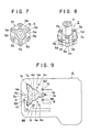
- Figs. 1 to 13 illustrate several embodiments of the invention, in which, Fig. 1 is a mid-vertical section of a brushless motor; Fig. 2 is a bottom plan view showing an example of a stator set; Fig. 3 is an enlarged perspective view showing the central portion of the bottom of the stator set in Fig. 2; Fig. 4 is an enlarged schematic perspective view illustrating principal parts shown in Fig. 3; Fig. 5 is an enlarged sectional view of terminal portion shown in Fig. 1; Fig. 6 is a plan view of a stator core; Fig. 7 is a plan view of a bearing holder; Fig. 8 is a perspective view of the bearing holder; Fig. 9 is a plan view of a substrate; Fig.
- FIG. 10 is a development illustrating winding method of a stator coil
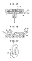
- Figs. 11, 12 and Fig. 13 are side elevations which show other examples of terminals
- Figs. 14 and 15 are mid-vertical sections, each illustrating conventional brushless motor
- Fig. 16 is a development which explanatorily shows how the stator coil is to be wound if the terminal is used in the conventional motor construction
- Fig. 17 is a perspective view illustrating a common terminal in such winding method as in Fig. 16.
- Fig. 1 shows an example of a brushless motor according to the present invention.
- This brushless motor comprises a rotor case 6 rotatably supported by a shaft 12, a rotor magnet 11 fixed in the internal peripheral wall of this case 6, a stator core 2 so disposed that its peripheral surfaces are in a facing relation with that of the magnet 11, a stator coil 7 wound to each salient pole 2e, a circuit substrate 4 which supports the stator core 2 and is connected to the stator coil 7, a core holder 3 for mounting fixedly the stator core 2 on the circuit substrate 4, and a bearing holder 5 having, a bearing 9 a provided therein and allowing the rotor shaft 12 to be rotatably supported by the substrate.
- This motor is driven by controlling respective stator coils 7 of respective phases through a rectifying system which is not illustrated, the system comprising a magnetic sensor, a semi-conductor switch and the like.
- a set of stator 1 is thus constituted by the foregoing stator core 2, stator coil 7 wound to a salient pole 2e of the stator core 2, core holder 3 made of insulating material such as resins, ceramics and the like, and a plurality of terminals 8 supported by the core holder 3.
- the terminal 8 of the set of stator 1 is connected to the circuit substrate 4 by soldering.
- the stator coil 7 is connected with the circuit substrate 4.
- the stator set 1 is placed on the circuit substrate 4 with the base of the core holder 3 in contact with the circuit substrate, the core holder being fitted to the center of the stator core 2.
- This stator set 1 is integrally fixed to the substrate 4, by means of vis 10, together with the bearing holder 5 which is to pass through-holes 2a, 3a formed respectively, centrally of the stator core 2 and the core holder 3 as well as through holes 4a of the substrate 4.
- the bearing holder 5 is inserted into those through-holes 2a, 3a, and 4a from top of the stator core 2, while the flange portion 5a formed in the upper end of the holder 5 is engaged upon a stepped part 2d of the stator core 2.
- the fixation of the holder 5 is carried out after sandwiching the stator core 2 and core holder 3 between the circuit substrate 4 and holder 5 per se.
- the stator coil 7 wound to the stator core 2 is connected with the terminal 8.
- the holes 2a, 3a which are defined centrally of both stator core 2 and core holder 3, are so formed with a collective mixture of circular holes as to generally represent a triangular shape on the whole, to permit insertion thereinto of central protrudent portion 5c of the bearing holder 5.
- the stator core 2 as shown in Figs. 3 and 6, are so formed with a collective mixture of circular holes as to generally represent a triangular shape on the whole, to permit insertion thereinto of central protrudent portion 5c of the bearing holder 5.
- the stator core 2 as shown in Figs.
- the core holder 3 as seen from Figs. 2 to 4, is formed at its base surface with base portions 3c to be contacted with the circuit substrate 4, which base portions 3c are disposed annually spaced apart from one another at given intervals, with grooves 3b being respectively defined in each space adjoining the base portions 3c.
- the grooves 3b as in Figs. 1 and 5, there are formed retaining sections 3d which project towards the upper layer side of the stator core 2, and the terminals 8 are mounted in the retaining sections 3d. Fixation of those retaining sections 3d is such that they are penetrated through the respective penetrated areas 2d of stator core 2 and fitted within recessions 2f formed in the peripheral wall of recessed part 2b.
- locating pins 3e are provided for the base 3c in order to locate the core holder in 3c respect to the circuit substrate, and also for the base 3c, there are provided through-holes 3f through which are passed the vises 10 for fixation.
- the bearing holder 5 has the bearing 9 provided therein, by means of which the shaft 12 is mounted rotatably to the circuit substrate 4.
- this bearing holder 5 is of a cylindrical form having a generally T-shaped configuration in section, which is provided with the flange portion 5a to be used for pressing the stator set 1 towards the side of circuit substrate 4, and with the central protrudent portion 5c to be fitted in the stator core 2, core holder 3 and circuit substrate 4.
- the flange portion 5a is formed with a vis through-hole 5b and further formed with recessed regions 5f adapted for avoiding contact of the flange portion with the retaining sections 3d.
- the central protrudent portion 5c is formed at its periphery with a plurality of projected parts 5d, and further a threaded hole 5e is formed in each of the projecting parts 5d.
- the circuit substrate 4 is mounted with a control circuit and the like to control electric supply to the stator coil 7 of the stator set 1 mentioned above.
- the circuit substrate 4 has also a function to support the stator set 1 and a rotor set.
- the circuit substrate 4 comprises a steel plate whose surface is provided with a copper-foiled circuit conductive pattern coated with insulating membrane.
- this circuit substrate 4 as depicted in Fig. 9, there is formed a through-hole 4a generally in triangular shape so dimensioned as to allow fit insertion thereinto of the central protrudent portion 5c and plural projected parts 5d of the bearing holder 5.
- through-hole 4a has, formed at its respective apexes, notched areas 4b in which the locating pins 3e of core holder 3 are fitted respectively.
- the circuit substrate 4 is also formed with through-holes 4c and cut-away part 4d which lie on the same circumference of circle along which are disposed the foregoing notched areas 4b defined peripherally of the through-hole 4a, the through-holes 4c and cut-away part 4d being so formed that other locating pins 3e of core holder 3 can be fitted thereinto.
- threaded holes 4e are formed at the points corresponding to vis through-holes 2c and 3f on the side of stator set 1.
- terminal points 13 such that they are disposed at the locations corresponding to the terminals 8 which are secured in the core holder 3.
- stator set 1, bearing holder 5 and substrate 4 are fitted together and juxtaposed with one another, and further integrally fixed by the vises 10.
- Those vises 10 pass through the vis through-holes 2c of stator core 2 and the through-holes 3f of core holder 3, and are screwed into the threaded holes 4e of circuit substrate 4.
- the terminal 8 as shown in Fig. 5, includes a base 8b and a tongue strip 8a, thereby being of U-shaped form, the base and tongue strip being inserted into the retaining section 3d of core holder 3. Leads 7a, 7d to 7f or a crossover track 7 are inserted and fixed between the base 8b and tongue strip 8a.
- the respective opposing surfaces of tongue strip 8a and base 8b are not affected from oxidation by fusing, the tongue strip and base retaining at lease leads 7a, 7d to 7f, or a crossover track 7b.
- the end of the terminal 8 to be connected with the terminal section 13 on the circuit substrate side 4 is not affected from oxidation by fusing, either.
- stator coil 7 A method of winding the stator coil 7 and connection of the stator coil 7 to the terminal 8 will now be described as below.
- the arrows given along the stator coil 7 show the direction in which the coil should be would, and that designations U, V and W given at the respective salient poles 2e of the respective phases, in Fig. 2, serve to facilitate the understanding about the respective winding start points and winding end points of the stator coils 7.
- winding of the stator coil 7 to the stator core 2 is, for example, carried out as illustrated in Figs. 2 and 10.
- lead 7a of the U-phase is inserted into the terminal 8A and temporarily fixed thereto by gently flattening the tongue strip 8a.
- the stator core 7 is wound up sequentially to respective corresponding cores 2e of the U-phase, using a coil-winding machine.
- the U-phase stator coil 7, when it finishes winding, is used as a crossover track 7b, and inserted into and passed through the common terminal 8B as illustrated in Figs. 2 to 4 and Fig. 10.
- the crossover track 7b thus passed from that terminal is now used as a lead for winding initiation of the V-phase, and such V-phase stator coil is wound up sequentially to the respective cores 2e of V-phase in a direction reversing the winding direction of the U-phase.
- the V-phase stator coil, after being wound up, is used further as a lead 7d, inserted into a terminal 8D, temporarily fixed thereto by flattening the tongue strip 8a gently, and then cut off.
- a lead 7e of the W-phase is inserted into a terminal 8E and temporarily fixed thereto by gently flattening the tongue strip 8a, and thereafter the lead is wound up to the respective cores of the W-phase in sequence.
- the wound-up stator coil is, as a lead 7f, inserted into and temporarily fixed by the common terminal 8B together with the coil crossover track 7b and only the lead 7f is cut off.
- the coil leads 7a, 7d, 7e, 7f and the coil crossover track 7b which are inserted into their respective terminals 8, are temporarily fixed to each terminal 8A, 8D, 8E, 8B, respectively and thereafter those coil leads and coil crossover track 7b are, as shown in Fig. 3 and Fig. 4, welded by fusing to the respective terminals 8A, 8D, 8E, 8B.
- Two electrodes 14, 15 are set on the opposite sides of the terminal 8, such that they are disposed respectively facing towards the base 8b and tongue strip 8a of the terminal 8, and then, while causing the electrodes to be pressed against the terminal, an electric currency is applied thereto, during which the coating on those leads is melt-stripped under Joule effect or heat generated by this fusing.
- the electrodes 14,15 on the right side are shown to be in the state where they are pressed to the terminal 8.
- stator core 2 is fixed to the substrate 4 through the core holder 3.
- Positioning of the stator core 2 in respect to the substrate 4 is conducted by inserting each locating pin 3e of core holder 3, respectively, into the notched areas 4b, through-holes 4c and cut-away parts 4d formed in the substrate 4.
- the terminal sections 13 of the substrate 4 are each applied a cream solder.
- the end 8c of the terminal 8 projecting toward the substrate 4 side is fixed by solder 16 with the terminal section 13.
- the bearing holder 5 is fitted in the stator core 2 and fixedly secured to the substrate 4 by means of the vises 10.
- the stator set 1, the bearing holder 5 and the substrate 4 are stacked in this order, according to the number of their associated parts mounted thereon, which therefore permits easy assembling and cost reduction for the assemblage.
- the terminal 8 shown in Fig. 11 is bent into L-shaped configuration, whereby its portion 8c which is in contact with the circuit substrate 4 is greater in dimensions so as to enhance a soldering effect between the terminal 8 and substrate 4.
- the terminal 8 shown in Fig. 12 is so bent into L-shaped configuration that its base portion 8b, which cooperates with the tongue strip 8a to retain the lead therebetween, is contacted with and fixed by soldering 16 to the circuit substrate 4. This not merely enhances the soldering effect between the terminal 8 and substrate 4, but also insures more positive connection between them. Additionally, such formation of the terminal 8 renders much thinner the stator set 1 and thus allows the motor to be formed in much thinner structure.
- Fig. 13 shows an example in which the terminal 8 has been formed, during press working process, taking into account especially the direction in which burr is created, so that burr is created at the sides of the terminal designated by characters A and B, and the lead can be easily cut off, using such burr.
- connection of the coil to the terminal may be effected by other soldering method than the foregoing fusing, namely such electric resistance welding as a spot welding or the like.
Landscapes
- Engineering & Computer Science (AREA)
- Power Engineering (AREA)
- Insulation, Fastening Of Motor, Generator Windings (AREA)
- Brushless Motors (AREA)
- Iron Core Of Rotating Electric Machines (AREA)
- Permanent Magnet Type Synchronous Machine (AREA)
Applications Claiming Priority (3)
| Application Number | Priority Date | Filing Date | Title |
|---|---|---|---|
| JP1988127955U JP2528848Y2 (ja) | 1988-09-29 | 1988-09-29 | 外転型ブラシレスモータ |
| JP127955/88U | 1988-09-29 | ||
| PCT/JP1989/000978 WO1990003686A1 (en) | 1988-09-29 | 1989-09-27 | Brushless motor |
Publications (3)
| Publication Number | Publication Date |
|---|---|
| EP0436721A1 true EP0436721A1 (de) | 1991-07-17 |
| EP0436721A4 EP0436721A4 (en) | 1991-11-06 |
| EP0436721B1 EP0436721B1 (de) | 1995-07-05 |
Family
ID=14972787
Family Applications (1)
| Application Number | Title | Priority Date | Filing Date |
|---|---|---|---|
| EP89910933A Expired - Lifetime EP0436721B1 (de) | 1988-09-29 | 1989-09-27 | Verfahren zum zusammenbauen eines bürstenlosen motors |
Country Status (6)
| Country | Link |
|---|---|
| US (1) | US5173628A (de) |
| EP (1) | EP0436721B1 (de) |
| JP (1) | JP2528848Y2 (de) |
| KR (1) | KR910007562Y1 (de) |
| DE (1) | DE68923375T2 (de) |
| WO (1) | WO1990003686A1 (de) |
Cited By (4)
| Publication number | Priority date | Publication date | Assignee | Title |
|---|---|---|---|---|
| EP0582714A4 (de) * | 1991-04-30 | 1994-08-31 | Kabushiki Kaisha Sankyo Seiki Seisakusho | |
| EP0903837A2 (de) * | 1997-09-19 | 1999-03-24 | Victor Company Of Japan, Ltd. | Motor, Statorstruktur des Motors und Montageverfahren für den Stator |
| EP1551091A1 (de) * | 2002-09-24 | 2005-07-06 | Sawafuji Electric Co., Ltd | STATOR FüR EINEN AUSSENROTOR-MULTIPOLGENERATOR UND VERFAHREN ZUM ZUSAMMENBAU DESSTATORS |
| US7546672B2 (en) | 2006-04-20 | 2009-06-16 | Makita Corporation | Methods for manufacturing a motor |
Families Citing this family (45)
| Publication number | Priority date | Publication date | Assignee | Title |
|---|---|---|---|---|
| JP3157850B2 (ja) * | 1991-04-12 | 2001-04-16 | 日本電産株式会社 | スピンドルモータ |
| JPH0624365U (ja) * | 1991-11-29 | 1994-03-29 | 株式会社三協精機製作所 | ブラシレスモータ |
| JPH0588169U (ja) * | 1992-04-22 | 1993-11-26 | マブチモーター株式会社 | 小型モータ |
| JP2563740Y2 (ja) * | 1992-05-14 | 1998-02-25 | 株式会社三協精機製作所 | ブラシレスモータ |
| JP2881528B2 (ja) * | 1992-05-15 | 1999-04-12 | ミネベア株式会社 | フラットモータのステータ構造 |
| US5436517A (en) * | 1992-08-24 | 1995-07-25 | Nagano Nidec Corporation | Recording disk driving apparatus |
| JPH0684781U (ja) * | 1993-05-13 | 1994-12-02 | 株式会社三協精機製作所 | ブラシレスモータ |
| JP2668636B2 (ja) * | 1993-06-29 | 1997-10-27 | 株式会社三協精機製作所 | モータ |
| JPH07177720A (ja) * | 1993-12-22 | 1995-07-14 | Matsushita Electric Ind Co Ltd | ブラシレスモータ |
| US5705866A (en) * | 1994-06-09 | 1998-01-06 | Nidec Corporation | Spindle motor |
| JP3428161B2 (ja) * | 1994-08-05 | 2003-07-22 | 松下電器産業株式会社 | モータ |
| KR960025765U (ko) * | 1994-12-30 | 1996-07-22 | 일체형 스테이터 코어를 갖는 브레쉬레스 모터 | |
| JPH08308197A (ja) * | 1995-05-08 | 1996-11-22 | Matsushita Electric Ind Co Ltd | スピンドルモータ |
| JP3768571B2 (ja) * | 1995-10-06 | 2006-04-19 | 日本電産株式会社 | スピンドルモータ |
| KR200158695Y1 (ko) * | 1996-11-19 | 1999-10-15 | 이형도 | 모터의 베어링 고정장치 |
| JP3366201B2 (ja) * | 1996-12-13 | 2003-01-14 | 株式会社三協精機製作所 | ブラシレスモータおよびその製造方法 |
| JP3052306B2 (ja) * | 1997-02-28 | 2000-06-12 | 日本精機株式会社 | ステッピングモータの接続構造 |
| JPH1198770A (ja) * | 1997-09-19 | 1999-04-09 | Victor Co Of Japan Ltd | モータのステータ構造及びモータのステータ組立方法 |
| JPH11103551A (ja) * | 1997-09-29 | 1999-04-13 | Sawafuji Electric Co Ltd | アウタロータ型多極発電機におけるコイル接続構造 |
| DE19748150B4 (de) * | 1997-10-31 | 2006-02-23 | Minebea Co., Ltd. | Spindelmotor mit Kontaktierung |
| US6069428A (en) * | 1998-01-21 | 2000-05-30 | Fasco Industries, Inc. | Brushless DC motor assembly |
| US6365995B1 (en) * | 1998-11-20 | 2002-04-02 | Matsushita Electric Industrial Co., Ltd. | Brushless motor and its assembly method |
| JP2000287402A (ja) * | 1999-03-31 | 2000-10-13 | Sawafuji Electric Co Ltd | アウタロータ型多極発電機用ステータ |
| JP2000295812A (ja) * | 1999-04-02 | 2000-10-20 | Seiko Instruments Inc | モータ、モータの製造方法、及び回転体装置 |
| US6603227B2 (en) * | 2001-04-16 | 2003-08-05 | Briggs & Stratton Corporation | Small engine vehicle including a generator |
| US6921993B2 (en) * | 2003-09-16 | 2005-07-26 | Seagate Technology Llc | Geometrically aligning a stator and a base plate for a spindle motor |
| JP4406864B2 (ja) * | 2003-09-30 | 2010-02-03 | 株式会社ヴァレオサーマルシステムズ | 電磁モータ |
| US6982532B2 (en) | 2003-12-08 | 2006-01-03 | A. O. Smith Corporation | Electric machine |
| US7342334B2 (en) * | 2004-10-29 | 2008-03-11 | Emerson Electric Co. | Insulated stator with wire routing element |
| JP4660310B2 (ja) * | 2004-11-04 | 2011-03-30 | 株式会社デンソー | 三相磁石式発電機 |
| JP2006304489A (ja) * | 2005-04-20 | 2006-11-02 | Nidec Sankyo Corp | ブラシレスモータ |
| JP4722588B2 (ja) * | 2005-06-30 | 2011-07-13 | 本田技研工業株式会社 | 回転電機のステータおよびその製造方法 |
| JP2007151349A (ja) * | 2005-11-29 | 2007-06-14 | Nippon Densan Corp | モータ |
| JP4864469B2 (ja) * | 2006-01-25 | 2012-02-01 | カルソニックカンセイ株式会社 | ブロワモータのラジオノイズ対策構造 |
| US7671495B2 (en) * | 2006-11-20 | 2010-03-02 | Asmo Co., Ltd. | Armature and motor |
| JP4986974B2 (ja) * | 2007-10-26 | 2012-07-25 | 日東工器株式会社 | ステータ |
| JP4535146B2 (ja) | 2008-02-27 | 2010-09-01 | 株式会社デンソー | コイルの固定部材及び回転電機 |
| KR101070042B1 (ko) * | 2009-12-28 | 2011-10-04 | 삼성전기주식회사 | 모터 장치 및 상기 모터 장치를 제조하는 제조 방법 |
| KR101196607B1 (ko) * | 2010-06-16 | 2012-11-02 | 엘지이노텍 주식회사 | 스핀들 모터 |
| US8872401B2 (en) * | 2012-10-05 | 2014-10-28 | Asia Vital Components (China) Co., Ltd. | Securing structure for fan sensing element |
| JP6346865B2 (ja) * | 2015-03-16 | 2018-06-20 | ミネベアミツミ株式会社 | モータ |
| WO2018105596A1 (ja) * | 2016-12-06 | 2018-06-14 | デンソートリム株式会社 | 内燃機関用回転電機およびそのステータ |
| DE102019102316A1 (de) * | 2019-01-30 | 2020-07-30 | Nidec Gpm Gmbh | Pumpe mit direkter Anbindung des Stators an die Leiterplatte |
| DE102019102320A1 (de) * | 2019-01-30 | 2020-07-30 | Nidec Corporation | Elektrischer Antrieb mit direkter Anbindung des Stators an die Leiterplatte |
| US12074498B2 (en) * | 2020-10-08 | 2024-08-27 | Asia Vital Components (China) Co., Ltd. | Fan stator structure |
Citations (5)
| Publication number | Priority date | Publication date | Assignee | Title |
|---|---|---|---|---|
| GB1236508A (en) * | 1969-11-13 | 1971-06-23 | Controls Co Of America | Improvements in and relating to dynamoelectric machines |
| FR2256573A1 (de) * | 1973-12-26 | 1975-07-25 | Rotron Inc | |
| US4554491A (en) * | 1984-08-10 | 1985-11-19 | Msl Industries, Inc. | Brushless DC motor having a laminated stator with a single stator winding |
| JPS61147762A (ja) * | 1984-12-20 | 1986-07-05 | Mitsubishi Electric Corp | ブラシレスモ−タ |
| US4633110A (en) * | 1985-03-20 | 1986-12-30 | Rotron, Inc. | Motor with stator on printed circuit assembly |
Family Cites Families (13)
| Publication number | Priority date | Publication date | Assignee | Title |
|---|---|---|---|---|
| JPS52118501A (en) * | 1976-03-31 | 1977-10-05 | Matsushita Electric Ind Co Ltd | Motor |
| JPS5959036A (ja) * | 1982-09-28 | 1984-04-04 | Nippon Denso Co Ltd | 扁平コイルの端子構造 |
| JPS60153667U (ja) * | 1984-03-22 | 1985-10-14 | 株式会社安川電機 | ブラシレスモ−タ |
| JPS6162580U (de) * | 1984-09-29 | 1986-04-26 | ||
| JPS61150653A (ja) * | 1984-12-21 | 1986-07-09 | Mitsubishi Electric Corp | ブラシレスモ−タ |
| DE3505092A1 (de) * | 1985-02-14 | 1986-08-21 | Papst-Motoren GmbH & Co KG, 7742 St Georgen | Lackdrahtkontaktverbindung zu leiterplatten |
| US4779330A (en) * | 1985-03-20 | 1988-10-25 | Comair Rotron, Inc. | Method for manufacturing motor with stator on printed circuit assembly |
| JPS61169470U (de) * | 1985-04-03 | 1986-10-21 | ||
| DE8690117U1 (de) * | 1985-09-18 | 1987-09-03 | Papst-Motoren GmbH & Co KG, 7742 St Georgen | Elektromotor |
| US4682065A (en) * | 1985-11-13 | 1987-07-21 | Nidec-Torin Corporation | Molded plastic motor housing with integral stator mounting and shaft journalling projection |
| JPS6351578U (de) * | 1986-09-19 | 1988-04-07 | ||
| JPS63228937A (ja) * | 1987-03-16 | 1988-09-22 | Mitsubishi Electric Corp | ブラシレスモ−タの端子装置 |
| JPH0228937A (ja) * | 1988-07-19 | 1990-01-31 | Matsushita Electron Corp | 半導体装置 |
-
1988
- 1988-09-29 JP JP1988127955U patent/JP2528848Y2/ja not_active Expired - Lifetime
-
1989
- 1989-09-18 KR KR2019890013571U patent/KR910007562Y1/ko not_active IP Right Cessation
- 1989-09-27 EP EP89910933A patent/EP0436721B1/de not_active Expired - Lifetime
- 1989-09-27 US US07/668,495 patent/US5173628A/en not_active Expired - Lifetime
- 1989-09-27 DE DE68923375T patent/DE68923375T2/de not_active Expired - Fee Related
- 1989-09-27 WO PCT/JP1989/000978 patent/WO1990003686A1/ja active IP Right Grant
Patent Citations (5)
| Publication number | Priority date | Publication date | Assignee | Title |
|---|---|---|---|---|
| GB1236508A (en) * | 1969-11-13 | 1971-06-23 | Controls Co Of America | Improvements in and relating to dynamoelectric machines |
| FR2256573A1 (de) * | 1973-12-26 | 1975-07-25 | Rotron Inc | |
| US4554491A (en) * | 1984-08-10 | 1985-11-19 | Msl Industries, Inc. | Brushless DC motor having a laminated stator with a single stator winding |
| JPS61147762A (ja) * | 1984-12-20 | 1986-07-05 | Mitsubishi Electric Corp | ブラシレスモ−タ |
| US4633110A (en) * | 1985-03-20 | 1986-12-30 | Rotron, Inc. | Motor with stator on printed circuit assembly |
Non-Patent Citations (2)
| Title |
|---|
| PATENT ABSTRACTS OF JAPAN vol. 10, no. 347 (E-457)(2403) 21 November 1986, & JP-A-61 147762 (MITSUBISHI) 05 July 1986, * |
| See also references of WO9003686A1 * |
Cited By (6)
| Publication number | Priority date | Publication date | Assignee | Title |
|---|---|---|---|---|
| EP0582714A4 (de) * | 1991-04-30 | 1994-08-31 | Kabushiki Kaisha Sankyo Seiki Seisakusho | |
| EP0903837A2 (de) * | 1997-09-19 | 1999-03-24 | Victor Company Of Japan, Ltd. | Motor, Statorstruktur des Motors und Montageverfahren für den Stator |
| EP0903837A3 (de) * | 1997-09-19 | 2001-11-07 | Victor Company Of Japan, Ltd. | Motor, Statorstruktur des Motors und Montageverfahren für den Stator |
| EP1551091A1 (de) * | 2002-09-24 | 2005-07-06 | Sawafuji Electric Co., Ltd | STATOR FüR EINEN AUSSENROTOR-MULTIPOLGENERATOR UND VERFAHREN ZUM ZUSAMMENBAU DESSTATORS |
| EP1551091A4 (de) * | 2002-09-24 | 2009-01-07 | Sawafuji Electric Co Ltd | STATOR FüR EINEN AUSSENROTOR-MULTIPOLGENERATOR UND VERFAHREN ZUM ZUSAMMENBAU DESSTATORS |
| US7546672B2 (en) | 2006-04-20 | 2009-06-16 | Makita Corporation | Methods for manufacturing a motor |
Also Published As
| Publication number | Publication date |
|---|---|
| US5173628A (en) | 1992-12-22 |
| JP2528848Y2 (ja) | 1997-03-12 |
| DE68923375D1 (de) | 1995-08-10 |
| KR910007562Y1 (ko) | 1991-09-27 |
| JPH0249373U (de) | 1990-04-05 |
| EP0436721A4 (en) | 1991-11-06 |
| EP0436721B1 (de) | 1995-07-05 |
| DE68923375T2 (de) | 1996-03-14 |
| KR900007575U (ko) | 1990-04-04 |
| WO1990003686A1 (en) | 1990-04-05 |
Similar Documents
| Publication | Publication Date | Title |
|---|---|---|
| US5173628A (en) | Brushless motor | |
| US4633110A (en) | Motor with stator on printed circuit assembly | |
| JP3428161B2 (ja) | モータ | |
| US5519271A (en) | Stator of rotating electric machine | |
| JPH1118345A (ja) | 回転電機の固定子 | |
| JP2603799B2 (ja) | ブラシレスモータ | |
| JP3255160B2 (ja) | ブラシレスモータ及びその組立方法 | |
| JP2002300745A (ja) | 回転電機固定子コイルの結線装置 | |
| US4779330A (en) | Method for manufacturing motor with stator on printed circuit assembly | |
| JPH0759288A (ja) | ブラシレスモータのステータ | |
| JP2588898Y2 (ja) | ブラシレスモータの巻線端接続構造 | |
| CN114938695A (zh) | 具有一体式固定结构的用于定子绕组的电路板 | |
| JP3169798B2 (ja) | 電動モータの固定子の製造方法 | |
| JPH09121496A (ja) | 電動機 | |
| JP2590753Y2 (ja) | 回転電機の接続装置 | |
| JPH1041155A (ja) | 固定コイル | |
| JP2578620Y2 (ja) | 空芯コイル | |
| US6894419B2 (en) | Current passing circuit board for rotary electric machine inserted in molded resin | |
| JPH10309054A (ja) | モータ | |
| JP3291420B2 (ja) | 回転電機のステータ及びコイルの端末処理方法 | |
| JPS6116791Y2 (de) | ||
| JPH07143699A (ja) | 電動機 | |
| JP2996042B2 (ja) | ブラシレスモータ | |
| JPH0540683Y2 (de) | ||
| JPH0210791Y2 (de) |
Legal Events
| Date | Code | Title | Description |
|---|---|---|---|
| PUAI | Public reference made under article 153(3) epc to a published international application that has entered the european phase |
Free format text: ORIGINAL CODE: 0009012 |
|
| 17P | Request for examination filed |
Effective date: 19910325 |
|
| AK | Designated contracting states |
Kind code of ref document: A1 Designated state(s): DE FR GB NL |
|
| A4 | Supplementary search report drawn up and despatched |
Effective date: 19910916 |
|
| AK | Designated contracting states |
Kind code of ref document: A4 Designated state(s): DE FR GB NL |
|
| 17Q | First examination report despatched |
Effective date: 19930304 |
|
| GRAA | (expected) grant |
Free format text: ORIGINAL CODE: 0009210 |
|
| AK | Designated contracting states |
Kind code of ref document: B1 Designated state(s): DE FR GB NL |
|
| PG25 | Lapsed in a contracting state [announced via postgrant information from national office to epo] |
Ref country code: NL Free format text: LAPSE BECAUSE OF NON-PAYMENT OF DUE FEES Effective date: 19950705 Ref country code: FR Effective date: 19950705 |
|
| REF | Corresponds to: |
Ref document number: 68923375 Country of ref document: DE Date of ref document: 19950810 |
|
| PG25 | Lapsed in a contracting state [announced via postgrant information from national office to epo] |
Ref country code: GB Effective date: 19951005 |
|
| EN | Fr: translation not filed | ||
| NLV1 | Nl: lapsed or annulled due to failure to fulfill the requirements of art. 29p and 29m of the patents act | ||
| PLBE | No opposition filed within time limit |
Free format text: ORIGINAL CODE: 0009261 |
|
| STAA | Information on the status of an ep patent application or granted ep patent |
Free format text: STATUS: NO OPPOSITION FILED WITHIN TIME LIMIT |
|
| GBPC | Gb: european patent ceased through non-payment of renewal fee |
Effective date: 19951005 |
|
| 26N | No opposition filed | ||
| PGFP | Annual fee paid to national office [announced via postgrant information from national office to epo] |
Ref country code: DE Payment date: 20031009 Year of fee payment: 15 |
|
| PG25 | Lapsed in a contracting state [announced via postgrant information from national office to epo] |
Ref country code: DE Free format text: LAPSE BECAUSE OF NON-PAYMENT OF DUE FEES Effective date: 20050401 |