EP0410254B1 - Farbkasten für Druckmaschinen - Google Patents
Farbkasten für Druckmaschinen Download PDFInfo
- Publication number
- EP0410254B1 EP0410254B1 EP90113565A EP90113565A EP0410254B1 EP 0410254 B1 EP0410254 B1 EP 0410254B1 EP 90113565 A EP90113565 A EP 90113565A EP 90113565 A EP90113565 A EP 90113565A EP 0410254 B1 EP0410254 B1 EP 0410254B1
- Authority
- EP
- European Patent Office
- Prior art keywords
- ink fountain
- ink
- roller
- fans
- printing
- Prior art date
- Legal status (The legal status is an assumption and is not a legal conclusion. Google has not performed a legal analysis and makes no representation as to the accuracy of the status listed.)
- Expired - Lifetime
Links
- 238000007639 printing Methods 0.000 title claims abstract description 13
- 238000009413 insulation Methods 0.000 claims description 7
- 230000007797 corrosion Effects 0.000 abstract description 4
- 238000005260 corrosion Methods 0.000 abstract description 4
- 239000000839 emulsion Substances 0.000 abstract description 3
- 238000013016 damping Methods 0.000 abstract 1
- 239000011810 insulating material Substances 0.000 abstract 1
- 238000010438 heat treatment Methods 0.000 description 4
- 238000004519 manufacturing process Methods 0.000 description 2
- 230000001105 regulatory effect Effects 0.000 description 2
- 230000006641 stabilisation Effects 0.000 description 2
- 238000011105 stabilization Methods 0.000 description 2
- 229920006328 Styrofoam Polymers 0.000 description 1
- 238000009825 accumulation Methods 0.000 description 1
- XAGFODPZIPBFFR-UHFFFAOYSA-N aluminium Chemical compound [Al] XAGFODPZIPBFFR-UHFFFAOYSA-N 0.000 description 1
- 229910052782 aluminium Inorganic materials 0.000 description 1
- 230000033228 biological regulation Effects 0.000 description 1
- 238000007664 blowing Methods 0.000 description 1
- 239000003795 chemical substances by application Substances 0.000 description 1
- 238000000576 coating method Methods 0.000 description 1
- 230000001419 dependent effect Effects 0.000 description 1
- 230000037431 insertion Effects 0.000 description 1
- 238000003780 insertion Methods 0.000 description 1
- 238000009434 installation Methods 0.000 description 1
- 239000012774 insulation material Substances 0.000 description 1
- 238000003475 lamination Methods 0.000 description 1
- 239000000463 material Substances 0.000 description 1
- 238000007645 offset printing Methods 0.000 description 1
- 239000008261 styrofoam Substances 0.000 description 1
- 230000008646 thermal stress Effects 0.000 description 1
- 238000005406 washing Methods 0.000 description 1
- XLYOFNOQVPJJNP-UHFFFAOYSA-N water Substances O XLYOFNOQVPJJNP-UHFFFAOYSA-N 0.000 description 1
Images

Classifications
-
- B—PERFORMING OPERATIONS; TRANSPORTING
- B41—PRINTING; LINING MACHINES; TYPEWRITERS; STAMPS
- B41F—PRINTING MACHINES OR PRESSES
- B41F31/00—Inking arrangements or devices
- B41F31/002—Heating or cooling of ink or ink rollers
Definitions
- the invention relates to an ink fountain for printing machines according to the preamble of the first claim.
- the ink fountain side parts are first set against the ink fountain roller and there is rough regulation of the ink metering device, e.g. B. the color meter or the color metering elements with the machine stopped.
- the inking unit see DE patent application Az. F 10648, At .: 23.06.51
- the ink fountain see DE utility model 1 675 338
- parts of the ink fountain DE- OS 3 325 005, US-A-2 268 594
- the color metering device DE utility model 1 891 449
- thermal expansions against one another are also brought to a limited extent, so that the thermal stresses in the ink fountain, the dosing means and the ink fountain roller partially cancel each other out.
- Reduced tension due to thermal expansion leads to fewer ink fluctuations on the ink fountain roller, which can be more easily adjusted by the printer.
- the thermal insulation on the bottom and back of the ink fountain reduces the annoying heating of these parts, which are particularly exposed to the hot air flow from the sheet guiding devices of the machine.
- the side of the ink fountain facing the ink fountain roller is only slightly affected by the warm machine air, depending on the installation conditions. This part of the ink fountain is then at a lower temperature than the rest of the ink fountain body. To equalize the temperature, the hot air flow is directed by fans and baffles at the ink fountain edge on the metering side. This reduces the temperature gradient to less than 1 degree. Due to this low temperature gradient, correspondingly lower tensions occur in the ink fountain lower part, the metering elements and the ink fountain roller, i.e. H. the set color gap is subject to fewer fluctuations in the thickness, which can be more easily adjusted by the printer without the need for temperature control or additional heating.
- the invention also brings about a temperature control of the printing ink and a stabilization of the ink / fountain solution emulsion. Since the air from the sheet guiding systems of the machine heats up after a short period of operation, the ink is heated by blowing on the ink fountain roller. Because of this temperature control, the printing ink shows a much more uniform viscosity behavior in the warm-up phase of the machine, which is also important for constant Color guide is.
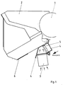
- the ink fountain 2 shown in FIGS. 1 and 2 is deposited on both sides on supports which are connected by a cross member 5 and can be inserted into the machine as a whole via rails of the machine frame (not shown here). This operating position is defined by stops, not shown, which end the insertion movement.
- the ink fountain 2 is arranged such that it can be pivoted away from the ink fountain roller 1 via a pivot point, not shown.
- the ink fountain 2 is delimited on the two end faces in a known manner by in each case one ink fountain side part, the end face of which is provided with a recess corresponding to the surface curvature of the ink fountain roller 1. This will cause the color to leak in the Contacting area prevented.
- the pivoting movement of the ink fountain 2 to the ink fountain roller 1 takes place via a toggle lever (not shown) and a swivel gear, also in a known manner.
- the underside of the ink fountain fuselage is provided with thermal insulation 6.
- a middle region (1/2) of the side of the ink fountain body facing the ink fountain roller 1 is acted upon by a warm air flow during the operating time of the printing press, which is increased by fans 3.
- the fans 3 are in the vicinity of a heat source arising in the operating time in the printing press, e.g. B. arranged below the ink fountain 2 above a sheet guide drum, so that the hot air flow from this drum acts on this area of the ink fountain 2.
- the fans 3 are surrounded by a guide device 4 such that the hot air is said middle area comes exactly into the gap between the ink fountain roller 1 and the side of the ink fountain body facing this. In this way, all essential parts of the ink fountain 2 are washed around evenly.
- thermal insulation 6 As insulation material against the flow of warm air, for example, three mm thick styrofoam (registered trademark) with aluminum lamination is suitable as thermal insulation 6.
- FIGS. 1 and 2 The air flow is illustrated by arrows in FIGS. 1 and 2, while in FIG. 1 it is also indicated that the guiding device 4 encloses the traverse 5 and thereby leaves a gap to the ink fountain body between the guiding device and the traverse, the guiding device 4 being by means of a screw is attached to the traverse.
Landscapes
- Inking, Control Or Cleaning Of Printing Machines (AREA)
- Printing Plates And Materials Therefor (AREA)
- Packages (AREA)
Description
- Die Erfindung betrifft einen Farbkasten für Druckmaschinen nach dem Oberbegriff des 1. Patentanpruches.
- Farbkästen der genannten Gattung sind weit verbreitet und allgemein bekannt.
- Beim Offsetdruck hängt eine störungsfreie Druckproduktion im hohen Maße von der Gleichmäßigkeit der Farbdosierung ab. Üblicherweise werden zum Einstellen des Farbwerkes nach dem Einfüllen der Farbe zunächst die Farbkastenseitenteile an die Farbkastenwalze federnd angestellt und es wird eine grobe Regulierung der Farbdosiereinrichtung, z. B. des Farbmessers oder der Farbdosierelemente bei stillstehender Maschine vorgenommen.
- Aus der Praxis ist es bekannt, daß die Farbführung des Farbwerkes stark von Temperatureinflüssen abhängig ist. Unerwünschte örtliche Erwärmungen des Farbkastens, der Dosierelemente und der Farbkastenwalze führen über Verspannungen zu Farbschwankungen auf der Farbkastenwalze, die vom Drucker nur schwer auszuregeln sind. Diese Farbschwankungen treten vor allem nach kurzen Betriebsunterbrechungen der Maschine auf, z. B. bei Waschintervallen, Stoppern oder nach Produktionspausen.
- Zur Lösung der mit Temperaturschwankungen verbundenen Probleme ist es bereits bekannt, das Farbwerk (siehe DE-Patentanmeldung Az. F 10648, At.: 23.06.51), den Farbkasten (siehe DE-Gebrauchsmuster 1 675 338), Teile des Farbkastens (DE-OS 3 325 005, US-A-2 268 594) oder die Farbdosiereinrichtung (DE-Gebrauchsmuster 1 891 449) bei Maschinenstillstand oder bei laufender Maschine geregelt oder ungeregelt auf eine vorbestimmte Betriebstemperatur zu Erwärmen, gegebenenfalls auch abzukühlen, um insgesamt das Temperaturgefälle in den einzelnen Bauteilen klein zu halten. Durch eine derartige Erwärmung werden je nach Angriffspunkt der Wärme begrenzt auch Wärmedehnungen gegeneinander zur Wirkung gebracht, so daß sich die thermischen Verspannungen im Farbkasten, den Dosiermitteln und der Farbkastenwalze teilweise gegenseitig aufheben. Verringerte Verspannungen durch Wärmedehnungen führen zu geringeren Farbschwankungen auf der Farbkastenwalze, die vom Drucker leichter ausgeregelt werden können.
- Bei den bekannten Maßnahmen ist jedoch von Nachteil, daß stets eine zusätzliche, in der Temperatur regelbare Wärmequelle installiert werden muß, was nicht nur zusätzlichen Aufwand bedeutet, sondern unter Umständen an dem erforderlichen Angriffspunkt nur schwer möglich ist.
- Es ist Aufgabe der Erfindung, örtliche Wärmedehnungsunterschiede im Farbkasten, den Dosiermitteln und in der Farbkastenwalze zu beseitigen, ohne hierzu eine zusätzliche Wärmequelle installieren zu müssen. Zugleich soll ein Temperieren der Druckfarbe, Stabilisieren der Farb-Feuchtmittelemulsion und ein Korrosionsschutz der Fabkastenwalze erreicht werden.
- Es wurde gefunden, daß dies auf einfache Weise erreicht wird, indem Unter- und Rückseite des Farbkastens mit einer Wärmeisolierung versehen werden und zusätzlich ein Warmluftstrom aus der Maschine auf der Farbkastenwalze zugewandte Seite des Farbkastens und die Dosierwalze des Farbkastens gerichtet wird.
- Die Wärmedämmung an der Unter- und Rückseite des Farbkastens reduziert die störende Erwärmung dieser Partien, die dem Warmluftstrom aus den Bogenführungseinrichtungen der Maschine besonders ausgesetzt sind.
- Die der Farbkastenwalze zugewandte Seite des Farbkastens wird in Abhängigkeit von den Einbauverhältnissen nur wenig von der warmen Maschinenluft getroffen. Diese Partie des Farbkastens hat dann eine niedrigere Temperatur als der übrige Farbkastenrumpf. Zum Temperaturausgleich wird der Warmluftstrom durch Ventilatoren und Leitbleche auf die dosierseitige Farbkastenkante gerichtet. Dadurch wird das Temperaturgefälle auf unter 1 Grad reduziert. Durch dieses geringe Temperaturgefälle treten entsprechend geringere Verspannungen im Farbkastenunterteil, den Dosierelementen und der Farbkastenwalze auf, d. h. der eingestellte Farbspalt unterliegt weniger Schwankungen in der Dicke, die vom Drucker leichter ausgeregelt werden können, ohne daß eine Temperaturregelung oder eine zusätzliche Heizung erforderlich sind.
- Außer dem bereits beschriebenen Vermeiden der Wärmedehnungen bewirkt die Erfindung noch ein Temperieren der Druckfarbe sowie ein Stabilisieren der Farb- Feuchtmittelemulsion. Da sich die Luft aus den Bogenführungssystemen der Maschine schon nach kurzer Betriebszeit erwärmt, wird durch das Anblasen der Farbkastenwalze eine Temperierung der Druckfarbe erreicht. Aufgrund dieser Temperierung zeigt die Druckfarbe in der Warmlaufphase der Maschine ein deutlich gleichmäßigeres Viskositätsverhalten, das ebenfalls wichtig für konstante Farbführung ist.
- Nach längerer Betriebszeit der Maschine verhindert die Warmluftzufuhr zum Farbduktor eine übermäßige Anreicherung von Feuchtmittel in der Druckfarbe. Ein erhöhter Feuchtmittelgehalt kann zu Korrosionserscheinungen am Farbduktor und Farbdosierelementen führen. Aufwendige Beschichtungen der Farbkastenwalze mit korrosionsbeständigen Werkstoffen sind nicht erforderlich.
- Die Erfindung wird nachstehend anhand der Zeichnung in einem Ausführungsbeispiel erläutert.
- Es zeigen:
- Figur 1
- die Seitenansicht des Farbkastens,
- Figur 2
- die Ansicht X auf den Farbkasten gemäß Figur 1.
- Der in den Figuren 1 und 2 dargestellte Farbkasten 2 ist beidseitig auf Trägern abgesetzt, die durch eine Traverse 5 verbunden sind und kann über hier nicht näher dargestellte Schienen des Maschinengestells in die Maschine als Ganzes eingeschoben werden. Diese Betriebsstellung ist durch nicht dargestellte Anschläge definiert, die die Einschubbewegung beenden.
- Der Farbkasten 2 ist über nicht dargestellten Drehpunkt von der Farbkastenwalze 1 abschwenkbar angeordnet. Die Begrenzung des Farbkastens 2 an den beiden Stirnseiten erfolgt in bekannter Weise durch jeweils ein Farbkastenseitenteil, dessen Stirnfläche mit einer der Oberflächenkrümmung der Farbkastenwalze 1 entsprechenden Ausnehmung versehen ist. Dadurch wird ein Auslaufen der Farbe in dem Kontaktierungsbereich verhindert. Die Schwenkbewegung des Farbkastens 2 zur Farbkastenwalze 1 erfolgt über einen nicht dargestellten Kniehebel und ein Schwenkgetriebe ebenfalls in bekannter Weise.
- Um das teilweise gegenseitige Aufheben der Wärmedehnungen im Farbkasten, den nicht näher bezeichneten Dosiermitteln z. B. einem Farbmesser und der Farbkastenwalze zu ermöglichen, ohne hierzu zusätzliche Wärmequellen zu benötigen, ist die Unterseite des Farbkastenrumpfes mit einer Wärmedämmung 6 versehen. Ein mittlerer Bereich (1/2) der der Farbkastenwalze 1 zugewandten Seite des Farbkastenrumpfes wird von einem Warmluftstrom in der Betriebszeit der Druckmaschine entstehender Wärme verstärkt durch Ventilatoren 3 beaufschlagt. Die Ventilatoren 3 sind in der Nähe einer in der Betriebszeit in der Druckmaschine entstehenden Wärmequelle, z. B. unterhalb des Farbkastens 2 oberhalb einer Bogenführungstrommel angeordnet, so daß die Warmluftströmung aus dieser Trommel auf diesen Bereich des Farbkastens 2 einwirkt. Damit die Wärme mit dem durch die Ventilatoren 3 erzeugten hohen Volumenstrom möglichst verlustfrei dem mittleren Bereich (1/2) der Farbkastenwalze 1 zugewandten Seite des Farbkastenrumpfes zugeführt werden kann, sind die Ventilatoren 3 von einer Leitvorrichtung 4 umgeben, derart, daß die Warmluft dem genannten mittleren Bereich exakt in den Spalt zwischen der Farbkastenwalze 1 und der dieser zugewandten Seite des Farbkastenrumpfes gelangt. Auf diese Weise werden alle wesentlichen Teile des Farbkastens 2 gleichmäßig umspült.
- Es ist auch möglich, zusätzlich das hintere Abschlußblech des Farbkastens 2 zu isolieren.
- Als Isoliermaterial gegen den Warmluftstrom eignet sich beispielsweise als Wärmedämmung 6 drei mm dickes Styropor (eingetragenes Warenzeichen) mit Aluminiumkaschierung.
- Die Luftführung ist in Figur 1 und 2 durch Pfeile verdeutlicht, während in Figur 1 noch angedeutet ist, daß die Leitvorrichtung 4 die Traverse 5 umschließt und dabei einen Spalt zum Farbkastenrumpf zwischen der Leiteinrichtung und der Traverse offen läßt, wobei mittels einer Schraube die Leitvorrichtung 4 an der Traverse befestigt ist.
-
- 1 Wasserkastenwalze
- 2 Farbkasten
- 3 Lüfter
- 4 Leitvorrichtung
- 5 Traverse
- 6 Wärmedämmung
Claims (3)
- Farbkasten für Druckmaschinen mit Farbdosiereinrichtung, die mit einer Farbkastenwalze zusammenwirkt, bei dem die Farbkastenseitenteile mit dem Farbkastenrumpf verbunden und an die Stirnfläche der Farbkastenwalze anstellbar sind,
dadurch gekennzeichnet,
daß die Unterseite des Farbkastenrumpfes mit einer Wärmedämmung (6) versehen ist und daß ein mittlerer Bereich (1/2) der der Farbkastenwalze (1) zugewandten Seite des Farbkastenrumpfes von einem Warmluftstrom aus der Druckmaschine, verstärkt durch Ventilatoren (3), beaufschlagt ist. - Farbkasten nach Anspruch 1,
dadurch gekennzeichnet,
daß die Ventilatoren (3) in der Nähe von in der Betriebszeit in der Druckmaschine entstehenden Wärmequellen angeordnet von einer Leitvorrichtung (4) umgeben sind, so daß der hohe Volumenstrom der vorhandenen Warmluft möglichst verlustfrei dem mittleren Bereich (1/2) der der Farbkastenwalze (1) zugewandten Seite des Farbkastenrumpfes des Farbkastens (2) zugeführt wird. - Farbkasten nach Anspruch 1 und 2,
dadurch gekennzeichnet,
daß die Rückseite des Farbkastenrumpfes mit einer Wärmedämmung versehen ist.
Priority Applications (1)
| Application Number | Priority Date | Filing Date | Title |
|---|---|---|---|
| AT90113565T ATE99231T1 (de) | 1989-07-28 | 1990-07-16 | Farbkasten fuer druckmaschinen. |
Applications Claiming Priority (2)
| Application Number | Priority Date | Filing Date | Title |
|---|---|---|---|
| DE3925034A DE3925034C1 (de) | 1989-07-28 | 1989-07-28 | |
| DE3925034 | 1989-07-28 |
Publications (3)
| Publication Number | Publication Date |
|---|---|
| EP0410254A2 EP0410254A2 (de) | 1991-01-30 |
| EP0410254A3 EP0410254A3 (en) | 1991-08-14 |
| EP0410254B1 true EP0410254B1 (de) | 1993-12-29 |
Family
ID=6386051
Family Applications (1)
| Application Number | Title | Priority Date | Filing Date |
|---|---|---|---|
| EP90113565A Expired - Lifetime EP0410254B1 (de) | 1989-07-28 | 1990-07-16 | Farbkasten für Druckmaschinen |
Country Status (6)
| Country | Link |
|---|---|
| US (1) | US5046420A (de) |
| EP (1) | EP0410254B1 (de) |
| JP (1) | JPH074927B2 (de) |
| AT (1) | ATE99231T1 (de) |
| DE (2) | DE3925034C1 (de) |
| ES (1) | ES2048368T3 (de) |
Families Citing this family (11)
| Publication number | Priority date | Publication date | Assignee | Title |
|---|---|---|---|---|
| DE9017795U1 (de) * | 1990-10-08 | 1992-03-12 | MAN Roland Druckmaschinen AG, 6050 Offenbach | Thermoregler für eine um einen Druckformzylinder gelegte Druckform für wasserlosen Offset-Druck |
| GB9501272D0 (en) * | 1995-01-23 | 1995-03-15 | Gale Gate Invest Ltd | Improvements in or relating to printing |
| DE19504583C1 (de) * | 1995-02-11 | 1996-08-01 | Roland Man Druckmasch | Keilfarbkasten für eine Offsetdruckmaschine |
| DE19525529C1 (de) * | 1995-07-13 | 1996-06-05 | Koenig & Bauer Albert Ag | Verfahren zur Montage einer Dosiereinrichtung in einer Rotationsdruckmaschine |
| US5603263A (en) * | 1995-09-08 | 1997-02-18 | Heidelberger Druckmaschinen Ag | Scraper blade and ink scavenger for printing presses |
| DE19623349A1 (de) * | 1996-06-12 | 1997-12-18 | Baldwin Gegenheimer Gmbh | Temperierte Flüssigkeits-Übertragungsvorrichtung der graphischen Industrie |
| DE19750960C2 (de) * | 1996-11-26 | 2002-08-14 | Roland Man Druckmasch | Filmfarbwerk für eine Rotationsdruckmaschine |
| DE19717524C2 (de) * | 1997-04-25 | 2002-04-04 | Roland Man Druckmasch | Farbwerk für eine Druckmaschine |
| US6374769B1 (en) | 1998-09-17 | 2002-04-23 | Fort James Corporation | Fluid material application system employing tube-in-hose heat exchanger |
| DE10001764A1 (de) * | 2000-01-18 | 2001-08-02 | Koenig & Bauer Ag | Farbauftrageinrichtung |
| EP1415805A1 (de) * | 2002-10-28 | 2004-05-06 | Hauni Maschinenbau AG | Druckwerk mit Temperiereinrichtung |
Family Cites Families (12)
| Publication number | Priority date | Publication date | Assignee | Title |
|---|---|---|---|---|
| DE75716C (de) * | L. RÖDIGER und G. RÖDIGER in Berlin S.O., Adalbertstr. 76 | Vorrichtung zum Anwärmen des Farbwerks von Buchdruckpressen | ||
| DE10648C (de) * | 1880-01-11 | 1880-08-20 | T. CULPIN in London | Neuerungen an der Rechenführung von Erntemaschinen |
| FR559277A (fr) * | 1922-11-30 | 1923-09-12 | Procédé et appareils pour la préservation des rouleaux à revêtement de gélatine ou matière analogue utilisés dans l'imprimerie | |
| US1568382A (en) * | 1924-10-17 | 1926-01-05 | Otten Edward | Means for conditioning inking rolls |
| US2268594A (en) * | 1939-08-03 | 1942-01-06 | Huber J M Inc | Process of letterpress printing |
| US2691345A (en) * | 1949-02-05 | 1954-10-12 | Huebner Company | Combustion precipitronic process and apparatus |
| DE1891449U (de) * | 1963-07-12 | 1964-04-23 | Agfa Ag | Farbwerk fuer druckmaschinen. |
| US3415269A (en) * | 1967-01-24 | 1968-12-10 | Vapor Corp | Multiple positioned pilot controlled poppet valve |
| DD98642A1 (de) * | 1972-06-12 | 1973-07-12 | ||
| US4152986A (en) * | 1976-12-03 | 1979-05-08 | Dadowski Gilbert F | Method and apparatus for printing raised ink images |
| JPS56150553A (en) * | 1980-04-23 | 1981-11-21 | Hitachi Eng Co Ltd | Heat insulating device for ink for printer |
| DD211089A1 (de) * | 1982-11-03 | 1984-07-04 | Arndt Jentzsch | Farbkasten fuer druckmaschinen |
-
1989
- 1989-07-28 DE DE3925034A patent/DE3925034C1/de not_active Expired - Lifetime
-
1990
- 1990-07-16 EP EP90113565A patent/EP0410254B1/de not_active Expired - Lifetime
- 1990-07-16 AT AT90113565T patent/ATE99231T1/de not_active IP Right Cessation
- 1990-07-16 ES ES90113565T patent/ES2048368T3/es not_active Expired - Lifetime
- 1990-07-16 DE DE90113565T patent/DE59004004D1/de not_active Expired - Fee Related
- 1990-07-24 US US07/557,361 patent/US5046420A/en not_active Expired - Fee Related
- 1990-07-30 JP JP2199347A patent/JPH074927B2/ja not_active Expired - Fee Related
Also Published As
| Publication number | Publication date |
|---|---|
| ATE99231T1 (de) | 1994-01-15 |
| JPH03218835A (ja) | 1991-09-26 |
| DE3925034C1 (de) | 1990-08-09 |
| EP0410254A2 (de) | 1991-01-30 |
| US5046420A (en) | 1991-09-10 |
| EP0410254A3 (en) | 1991-08-14 |
| DE59004004D1 (de) | 1994-02-10 |
| ES2048368T3 (es) | 1994-03-16 |
| JPH074927B2 (ja) | 1995-01-25 |
Similar Documents
| Publication | Publication Date | Title |
|---|---|---|
| EP0410254B1 (de) | Farbkasten für Druckmaschinen | |
| EP0159474B1 (de) | Farbwerk für Offsetdruckmaschinen | |
| EP0403861B1 (de) | Verfahren zum schnellen Erreichen des Fortdruckzustandes | |
| EP0564936A1 (de) | Anilox-Offset-Druckeinheit mit einem Kurzfarbwerk | |
| DE2360611A1 (de) | Farbwerk fuer druckmaschinen | |
| DE3203500C2 (de) | Farbmesser und eine Einstellvorrichtung für ein Farbmesser | |
| DE69703345T2 (de) | Verfahren und vorrichtung zum bedrucken eines streifens zum verpacken von gelatinkapseln | |
| EP0150047A2 (de) | Flexodruckmaschine mit temperaturstabilisiertem Druckmaschinengestell | |
| DE4011039C2 (de) | Verfahren zum Befeuchten und Einfärben eines Plattenzylinders einer Mehrfarben-Offset-Bogenrotationsdruckmaschine | |
| DE3247761A1 (de) | Vorrichtung zur farbprofilabhaengigen feuchtmittelregelung an einem farbwerk von offsetdruckmaschinen | |
| DE2711553A1 (de) | Farbkasten fuer offset- oder hochdruckmaschinen | |
| EP0529257B1 (de) | Verfahren zum Einstellen eines Fortdruckfarbprofils | |
| EP0188238A2 (de) | Beheizbare Kalanderwalze mit einem einen Strömungsspalt bildenden Verdrängerkörper | |
| EP0098514B1 (de) | Farbwerk | |
| EP0131108B1 (de) | Farb- oder Feuchtwerk für Rotationsdruckmaschinen | |
| EP0094584B1 (de) | Farbkasten für Druckmaschinen | |
| DE19523072C2 (de) | Bogenblaseinrichtung für eine Druckmaschine | |
| EP0193912B1 (de) | Halterung für einen Thermodruckkopf | |
| EP0634271B1 (de) | Verfahren und Einrichtung zum Einstellen der Temperatur einer Druckfarbe im Farbwerk einer Druckmaschine | |
| DE9412965U1 (de) | Druckmaschinen-Vorrichtung | |
| DE102011076748A1 (de) | Strahldüsenstruktur und Verfahren zum Aufbringen eines Mediums auf eine sich bewegende Oberfläche | |
| EP0131103B1 (de) | Farbdosiervorrichtung an Buch- und Offsetdruckmaschinen | |
| DE19623348B4 (de) | Flüssigkeits-Übertragungsvorrichtung der graphischen Industrie | |
| JPH051142B2 (de) | ||
| DE2449344A1 (de) | Oelmahlwerk mit einer automatischen stelleinrichtung |
Legal Events
| Date | Code | Title | Description |
|---|---|---|---|
| PUAI | Public reference made under article 153(3) epc to a published international application that has entered the european phase |
Free format text: ORIGINAL CODE: 0009012 |
|
| AK | Designated contracting states |
Kind code of ref document: A2 Designated state(s): AT BE CH DE ES FR GB IT LI NL SE |
|
| PUAL | Search report despatched |
Free format text: ORIGINAL CODE: 0009013 |
|
| AK | Designated contracting states |
Kind code of ref document: A3 Designated state(s): AT BE CH DE ES FR GB IT LI NL SE |
|
| 17P | Request for examination filed |
Effective date: 19910711 |
|
| 17Q | First examination report despatched |
Effective date: 19930608 |
|
| ITF | It: translation for a ep patent filed | ||
| GRAA | (expected) grant |
Free format text: ORIGINAL CODE: 0009210 |
|
| AK | Designated contracting states |
Kind code of ref document: B1 Designated state(s): AT BE CH DE ES FR GB IT LI NL SE |
|
| REF | Corresponds to: |
Ref document number: 99231 Country of ref document: AT Date of ref document: 19940115 Kind code of ref document: T |
|
| ET | Fr: translation filed | ||
| REF | Corresponds to: |
Ref document number: 59004004 Country of ref document: DE Date of ref document: 19940210 |
|
| GBT | Gb: translation of ep patent filed (gb section 77(6)(a)/1977) |
Effective date: 19940114 |
|
| REG | Reference to a national code |
Ref country code: ES Ref legal event code: FG2A Ref document number: 2048368 Country of ref document: ES Kind code of ref document: T3 |
|
| PLBE | No opposition filed within time limit |
Free format text: ORIGINAL CODE: 0009261 |
|
| STAA | Information on the status of an ep patent application or granted ep patent |
Free format text: STATUS: NO OPPOSITION FILED WITHIN TIME LIMIT |
|
| 26N | No opposition filed | ||
| EAL | Se: european patent in force in sweden |
Ref document number: 90113565.7 |
|
| PGFP | Annual fee paid to national office [announced via postgrant information from national office to epo] |
Ref country code: CH Payment date: 19950614 Year of fee payment: 6 |
|
| PGFP | Annual fee paid to national office [announced via postgrant information from national office to epo] |
Ref country code: AT Payment date: 19950620 Year of fee payment: 6 |
|
| PGFP | Annual fee paid to national office [announced via postgrant information from national office to epo] |
Ref country code: NL Payment date: 19950629 Year of fee payment: 6 |
|
| PGFP | Annual fee paid to national office [announced via postgrant information from national office to epo] |
Ref country code: FR Payment date: 19960617 Year of fee payment: 7 |
|
| PGFP | Annual fee paid to national office [announced via postgrant information from national office to epo] |
Ref country code: SE Payment date: 19960619 Year of fee payment: 7 |
|
| PGFP | Annual fee paid to national office [announced via postgrant information from national office to epo] |
Ref country code: BE Payment date: 19960620 Year of fee payment: 7 |
|
| PG25 | Lapsed in a contracting state [announced via postgrant information from national office to epo] |
Ref country code: AT Effective date: 19960716 |
|
| PGFP | Annual fee paid to national office [announced via postgrant information from national office to epo] |
Ref country code: ES Payment date: 19960718 Year of fee payment: 7 |
|
| PG25 | Lapsed in a contracting state [announced via postgrant information from national office to epo] |
Ref country code: LI Effective date: 19960731 Ref country code: CH Effective date: 19960731 |
|
| PG25 | Lapsed in a contracting state [announced via postgrant information from national office to epo] |
Ref country code: NL Effective date: 19970201 |
|
| REG | Reference to a national code |
Ref country code: CH Ref legal event code: PL |
|
| PG25 | Lapsed in a contracting state [announced via postgrant information from national office to epo] |
Ref country code: FR Effective date: 19970328 |
|
| NLV4 | Nl: lapsed or anulled due to non-payment of the annual fee |
Effective date: 19970201 |
|
| REG | Reference to a national code |
Ref country code: FR Ref legal event code: ST |
|
| PG25 | Lapsed in a contracting state [announced via postgrant information from national office to epo] |
Ref country code: SE Effective date: 19970717 Ref country code: ES Free format text: LAPSE BECAUSE OF EXPIRATION OF PROTECTION Effective date: 19970717 |
|
| PG25 | Lapsed in a contracting state [announced via postgrant information from national office to epo] |
Ref country code: BE Free format text: LAPSE BECAUSE OF NON-PAYMENT OF DUE FEES Effective date: 19970731 |
|
| BERE | Be: lapsed |
Owner name: MAN ROLAND DRUCKMASCHINEN A.G. Effective date: 19970731 |
|
| EUG | Se: european patent has lapsed |
Ref document number: 90113565.7 |
|
| PGFP | Annual fee paid to national office [announced via postgrant information from national office to epo] |
Ref country code: GB Payment date: 19980612 Year of fee payment: 9 |
|
| PG25 | Lapsed in a contracting state [announced via postgrant information from national office to epo] |
Ref country code: GB Free format text: LAPSE BECAUSE OF NON-PAYMENT OF DUE FEES Effective date: 19990716 |
|
| GBPC | Gb: european patent ceased through non-payment of renewal fee |
Effective date: 19990716 |
|
| REG | Reference to a national code |
Ref country code: ES Ref legal event code: FD2A Effective date: 20010201 |
|
| PGFP | Annual fee paid to national office [announced via postgrant information from national office to epo] |
Ref country code: DE Payment date: 20020711 Year of fee payment: 13 |
|
| PG25 | Lapsed in a contracting state [announced via postgrant information from national office to epo] |
Ref country code: DE Free format text: LAPSE BECAUSE OF NON-PAYMENT OF DUE FEES Effective date: 20040203 |
|
| PG25 | Lapsed in a contracting state [announced via postgrant information from national office to epo] |
Ref country code: IT Free format text: LAPSE BECAUSE OF NON-PAYMENT OF DUE FEES;WARNING: LAPSES OF ITALIAN PATENTS WITH EFFECTIVE DATE BEFORE 2007 MAY HAVE OCCURRED AT ANY TIME BEFORE 2007. THE CORRECT EFFECTIVE DATE MAY BE DIFFERENT FROM THE ONE RECORDED. Effective date: 20050716 |