EP0385539B1 - Installation de traite - Google Patents
Installation de traite Download PDFInfo
- Publication number
- EP0385539B1 EP0385539B1 EP90200422A EP90200422A EP0385539B1 EP 0385539 B1 EP0385539 B1 EP 0385539B1 EP 90200422 A EP90200422 A EP 90200422A EP 90200422 A EP90200422 A EP 90200422A EP 0385539 B1 EP0385539 B1 EP 0385539B1
- Authority
- EP
- European Patent Office
- Prior art keywords
- milk
- measuring chamber
- milking
- milking plant
- partial vacuum
- Prior art date
- Legal status (The legal status is an assumption and is not a legal conclusion. Google has not performed a legal analysis and makes no representation as to the accuracy of the status listed.)
- Expired - Lifetime
Links
Images


Classifications
-
- A—HUMAN NECESSITIES
- A01—AGRICULTURE; FORESTRY; ANIMAL HUSBANDRY; HUNTING; TRAPPING; FISHING
- A01J—MANUFACTURE OF DAIRY PRODUCTS
- A01J5/00—Milking machines or devices
- A01J5/007—Monitoring milking processes; Control or regulation of milking machines
-
- A—HUMAN NECESSITIES
- A01—AGRICULTURE; FORESTRY; ANIMAL HUSBANDRY; HUNTING; TRAPPING; FISHING
- A01J—MANUFACTURE OF DAIRY PRODUCTS
- A01J5/00—Milking machines or devices
- A01J5/007—Monitoring milking processes; Control or regulation of milking machines
- A01J5/01—Milkmeters; Milk flow sensing devices
-
- A—HUMAN NECESSITIES
- A01—AGRICULTURE; FORESTRY; ANIMAL HUSBANDRY; HUNTING; TRAPPING; FISHING
- A01J—MANUFACTURE OF DAIRY PRODUCTS
- A01J5/00—Milking machines or devices
- A01J5/013—On-site detection of mastitis in milk
- A01J5/0133—On-site detection of mastitis in milk by using electricity, e.g. conductivity or capacitance
-
- A—HUMAN NECESSITIES
- A01—AGRICULTURE; FORESTRY; ANIMAL HUSBANDRY; HUNTING; TRAPPING; FISHING
- A01J—MANUFACTURE OF DAIRY PRODUCTS
- A01J5/00—Milking machines or devices
- A01J5/013—On-site detection of mastitis in milk
- A01J5/0136—On-site detection of mastitis in milk by using milk flow characteristics, e.g. differences between udder quarters or differences with previous milking runs
-
- A—HUMAN NECESSITIES
- A01—AGRICULTURE; FORESTRY; ANIMAL HUSBANDRY; HUNTING; TRAPPING; FISHING
- A01J—MANUFACTURE OF DAIRY PRODUCTS
- A01J5/00—Milking machines or devices
- A01J5/013—On-site detection of mastitis in milk
- A01J5/0138—On-site detection of mastitis in milk by using temperature
-
- A—HUMAN NECESSITIES
- A01—AGRICULTURE; FORESTRY; ANIMAL HUSBANDRY; HUNTING; TRAPPING; FISHING
- A01J—MANUFACTURE OF DAIRY PRODUCTS
- A01J5/00—Milking machines or devices
- A01J5/017—Automatic attaching or detaching of clusters
- A01J5/0175—Attaching of clusters
-
- A—HUMAN NECESSITIES
- A01—AGRICULTURE; FORESTRY; ANIMAL HUSBANDRY; HUNTING; TRAPPING; FISHING
- A01J—MANUFACTURE OF DAIRY PRODUCTS
- A01J5/00—Milking machines or devices
- A01J5/04—Milking machines or devices with pneumatic manipulation of teats
-
- A—HUMAN NECESSITIES
- A01—AGRICULTURE; FORESTRY; ANIMAL HUSBANDRY; HUNTING; TRAPPING; FISHING
- A01J—MANUFACTURE OF DAIRY PRODUCTS
- A01J5/00—Milking machines or devices
- A01J5/04—Milking machines or devices with pneumatic manipulation of teats
- A01J5/041—Milk claw
-
- A—HUMAN NECESSITIES
- A01—AGRICULTURE; FORESTRY; ANIMAL HUSBANDRY; HUNTING; TRAPPING; FISHING
- A01J—MANUFACTURE OF DAIRY PRODUCTS
- A01J5/00—Milking machines or devices
- A01J5/04—Milking machines or devices with pneumatic manipulation of teats
- A01J5/044—Milk lines or coupling devices for milk conduits
-
- A—HUMAN NECESSITIES
- A01—AGRICULTURE; FORESTRY; ANIMAL HUSBANDRY; HUNTING; TRAPPING; FISHING
- A01J—MANUFACTURE OF DAIRY PRODUCTS
- A01J5/00—Milking machines or devices
- A01J5/04—Milking machines or devices with pneumatic manipulation of teats
- A01J5/08—Teat-cups with two chambers
-
- A—HUMAN NECESSITIES
- A01—AGRICULTURE; FORESTRY; ANIMAL HUSBANDRY; HUNTING; TRAPPING; FISHING
- A01J—MANUFACTURE OF DAIRY PRODUCTS
- A01J7/00—Accessories for milking machines or devices
-
- A—HUMAN NECESSITIES
- A01—AGRICULTURE; FORESTRY; ANIMAL HUSBANDRY; HUNTING; TRAPPING; FISHING
- A01J—MANUFACTURE OF DAIRY PRODUCTS
- A01J7/00—Accessories for milking machines or devices
- A01J7/02—Accessories for milking machines or devices for cleaning or sanitising milking machines or devices
- A01J7/022—Clean-in-Place Systems, i.e. CIP, for cleaning the complete milking installation in place
-
- A—HUMAN NECESSITIES
- A01—AGRICULTURE; FORESTRY; ANIMAL HUSBANDRY; HUNTING; TRAPPING; FISHING
- A01J—MANUFACTURE OF DAIRY PRODUCTS
- A01J9/00—Milk receptacles
- A01J9/04—Milk receptacles with cooling arrangements
-
- G—PHYSICS
- G01—MEASURING; TESTING
- G01F—MEASURING VOLUME, VOLUME FLOW, MASS FLOW OR LIQUID LEVEL; METERING BY VOLUME
- G01F1/00—Measuring the volume flow or mass flow of fluid or fluent solid material wherein the fluid passes through a meter in a continuous flow
- G01F1/007—Measuring the volume flow or mass flow of fluid or fluent solid material wherein the fluid passes through a meter in a continuous flow by measuring the level variations of storage tanks relative to the time
-
- G—PHYSICS
- G01—MEASURING; TESTING
- G01F—MEASURING VOLUME, VOLUME FLOW, MASS FLOW OR LIQUID LEVEL; METERING BY VOLUME
- G01F3/00—Measuring the volume flow of fluids or fluent solid material wherein the fluid passes through the meter in successive and more or less isolated quantities, the meter being driven by the flow
- G01F3/36—Measuring the volume flow of fluids or fluent solid material wherein the fluid passes through the meter in successive and more or less isolated quantities, the meter being driven by the flow with stationary measuring chambers having constant volume during measurement
- G01F3/38—Measuring the volume flow of fluids or fluent solid material wherein the fluid passes through the meter in successive and more or less isolated quantities, the meter being driven by the flow with stationary measuring chambers having constant volume during measurement having only one measuring chamber
Definitions
- the present invention relates to a milking plant for milking cows, which plant comprises teat cups that are connectable to respective teats of a cow's udder, while the milk obtained from each udder quarter with the aid of the said teat cups is conveyed through a separate line to a milk measuring device, said milk measuring device includes four milk meters, whose separate discharge lines are coupled to a common discharge line terminating in a milk cooling tank.
- Such a milking plant is known from DD-A-41115; the milk meter described therein comprises four milk receptacles each provided with a separate measuring pipe, whereby the whole milk yield per udder quarter is catched and measured, whereafter the milk from the four receptacles and measuring pipes is pumped in a common discharge line. Such a measurement of the whole milk yield per udder quarter is relatively inaccurate.
- each milk meter includes a milk receptacle which is subjected to a partial vacuum, a measuring chamber which can be connected to a partial vacuum whereby the milk flows from the milk receptacle into the measuring chamber, and in that the measuring chamber is provided with a valve and an aperture for supplying compressed air, this compressed air operates the valve which disconnects the measuring chamber from the milk receptacle after this measuring chamber has been filled with a defined quantity of milk, the milk is pumped by this compressed air from the measuring chamber into the relevant separate discharge line and from the separate discharge line into the common discharge line.
- a milk meter which includes a milk receptacle and a measuring chamber.
- the milk flows under a partial vacuum from the milk receptacle into the measuring chamber, whereafter each time the level of the milk in the measuring chamber has reached a certain value, the measuring chamber is closed and a defined quantity of milk is pumped to a milk receiver by means of a pressure difference over the space above the milk level in the measuring chamber and a collector line connected to the output of the measuring chamber.
- the measuring chamber is closed by a solenoid lift system. By using compressed air this solenoid lift system is superfluous; the same compressed air for pumping the milk from the measuring chamber into the discharge lines can be used for closing the measuring chamber after the level of milk in the measuring chamber has reached a certain level.
- the air sucked along by the partial vacuum together with the milk from the relevant teat cup is separated therefrom in the milk meter. Consequently, milk containing air is passed from the teat cup into the milk meter, whereas it is only the milk that is discharged therefrom to the milk cooling tank; in this respect it should be noted that so far it usually has been the custom to effect the milk-air separation not earlier than in the milk cooling tank.
- the milk meter is provided with a valve rod which, in a first position under a partial vacuum, leaves the aperture between the milk receptacle and the measuring chamber open, and, in a second position by means of compressed air, closes same.
- a switching element with the aid of which, in a first switching position thereof, the partial vacuum is applied to cause the valve rod to be brought to its first position, and, in a second switching position thereof, compressed air is admitted to cause the valve rod to be brought to its second position.
- the measuring chamber is provided with a milk level sensor, by means of which it is established when a defined quantity of milk is contained therein, after which it produces a control signal to cause the switching element to be adjusted from its first position to its second position.
- the switching element may be adjusted from its second position to its first position after a fixed period of time.
- the milk level sensor may produce a control signal intended for a computer, in which the quantity of milk obtained from each udder quarter is recorded for each individual cow.
- the recording of this quantity and hence also that of the total quantity of milk obtained from each cow per unit of time, e.g. per day, may be kept on the basis of a progressive average calculated over a defined number of days.
- the measuring chamber when empty, is closed by a spherical body.
- this spherical body is of such a design that, when the milk flows from the milk receptacle into the measuring chamber, it floats on the milk contained therein.
- a non-return valve is included in the separate discharge pipe beyond the aperture in the measuring chamber, which aperture can be closed by the spherical body. Via this non-return valve the milk is passed from the measuring chamber, but only under the influence of compressed air.
- the non-return valve blocks any milk flow, which might be possible in case the pressure in the relevant discharge pipes would exceed that prevailing in the measuring chamber in front of the non-return valve. This situation might be conceivable, since the milk is discharged from four milk meters to the milk cooling tank through the same common discharge line.
- the presence of the non-return valve beyond the measuring chamber aperture that is closable by the spherical body implies that, during the milking operation, the first obtained milk fills the separate discharge pipe between the said aperture and the non-return valve, as a result of which, according to the invention, each time a cow is milked, the quantity of milk recorded in a computer is increased only once by the quantity of milk corresponding to the volume of the separate discharge pipe between the measuring chamber aperture that is closable by the spherical body and the non-return valve.
- the milk meter is provided with a lifting magnet which, by moving the spherical body, has for its object to establish a connection between the closed measuring chamber and the discharge lines.
- a milk meter is provided with a tube stop valve, with the aid of which the partial vacuum connection of the milk meter can be closed after milking.
- the end of the milking procedure can be detected by means of sensors, e.g. with the aid of a milk flow sensor which may be incorporated in the line between the teat cup and the milk meter or in the milk meter itself, or with the aid of the afore-mentioned milk level sensor.
- the tube stop valve includes a lifting mechanism to allow air to flow into the milk meter simultaneously with or immediately after closure of the partial vacuum connection of the measuring chamber. This can be effected with a certain amount of overpressure; a simpler method is to have the lifting mechanism be operated, in accordance with the invention, by a valve in the outer wall of the milk meter.
- the tube stop valve in accordance with the invention renders it possible, in a simple manner, to remove the partial vacuum in a teat cup before the teat cup is removed from the teat or drops down therefrom.
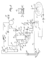
- FIG. 1 shows a schematic arrangement of a milking plant for milking cows. Only two milking parlours are shown by way of illustration, in each of which a cow is present.
- a milking robot 1 having four teat cups 2 at its end.
- the invention is completely independent of the manner in which the teat cups are connected; the teat cups may, combined in one single milking claw, be connected together as well as individually and independently of each other to respective teats of a cow's udder.
- the milk obtained from each udder quarter with the aid of the teat cups 2 can be conveyed through a separate line 3 (see Figure 2) to a milk measuring device 4. From the milk measuring device 4 the milk is conveyed via a circular line 5, to which the discharge lines of the various milk measuring devices in the various milking parlours are connected, to a milk cooling tank 6.
- the milk measuring device 4 comprises four milk meters 7, only one of which is shown in Figure 2.
- Figure 2 furthermore illustrates the basic arrangement of the milking plant, only one teat cup 2 and only one milk meter 7 having been shown in this arrangement for the sake of simplicity.
- the individual discharge lines 8 of the milk meters 7 are coupled to a common discharge line 9 which terminates in the milk cooling tank 6.
- Figure 3 is a more detailed representation of the basic structure of a milk meter as is incorporated in the milking plant shown in Figure 2.
- the milk meter 7 includes a milk receptacle 10 and a measuring chamber 11, in which connection the milk flows under a partial vacuum via the separate line 3 connected to the teat cup 2 from the milk receptacle 10 into the measuring chamber 11 and is pumped in defined quantities by means of compressed air from the measuring chamber 11 into the separate discharge line 8.
- the milk meter 7 includes a valve rod 12 which, in a first (shown) position under a vacuum, leaves the aperture 13 between the milk receptacle 10 and the measuring chamber 11 open, and, in a second (non-shown) position by means of compressed air, closes same.
- the milk meter includes a chamber 14, in which chamber the valve rod 12 has a piston 15.
- the valve rod 12 is capable of upward and downward movement in and through this chamber 14.
- the milk meter 7 is connected to a switching element 17 (see Figure 2).
- a switching element 17 In a first position of this switching element 17, a partial vacuum is applied to cause the valve rod 12 and the piston 15 to be moved downwardly to its first position, thereby leaving the aperture 13 open.
- compressed air In a second position of this switching element 17, compressed air is admitted into the space below the piston 15 to cause the valve rod 12 and the piston 15 to be moved upwardly to its second position, thereby closing the aperture 13.
- the milk meter 7 furthermore includes a tube 18 which, via relatively narrow apertures 19 and 20, is connected to the space in the chamber 14 below the piston and to the measuring chamber 11, respectively.
- a tube 18 which, via relatively narrow apertures 19 and 20, is connected to the space in the chamber 14 below the piston and to the measuring chamber 11, respectively.
- the measuring chamber 11 is provided with a milk level sensor 21, by means of which it is established when a defined quantity of milk is contained therein.
- this sensor 21 supplies a control signal S1 (see Figure 2) to cause the switching element 17 to be adjusted from its first position to its second position, so that the measuring chamber 11 can be emptied.
- S1 control signal
- the switching element 17 is adjusted from its second position to its first position; this period of time is of such a duration that there is sufficient time for the measuring chamber 11 to be emptied.
- the measuring chamber 11 can be filled again.
- the milk level sensor 21 can also apply a control signal S2 to a computer 22, in which the quantity of milk obtained from each udder quarter is recorded for each individual cow.
- a spherical body 23 In the lower part of the measuring chamber 11 there is provided a spherical body 23. When the measuring chamber 11 is empty, this spherical body 23 closes the aperture 24 between the measuring chamber 11 and the separate discharge line 8.
- the spherical body 23 is made of such a material that, when the milk flows from the milk receptacle 10 into the measuring chamber 11, it floats on the milk contained therein. When the milk is forced from the measuring chamber 11 into the separate discharge line 8, the aperture 24 is closed automatically by the spherical body 23 once the measuring chamber 11 is empty.
- a non-return valve 25 is arranged in the separate discharge line 8 beyond the aperture 24 in the measuring chamber, per- eferably as closely as possible therebeyond.
- this non-return valve 25 the milk is allowed to pass from the measuring chamber 11 but only under the influence of compressed air.
- the non-return valve 25 blocks any milk flow which might be possible in case, for whatever reason, the pressure in the relevant discharge lines would exceed that prevailing in the measuring chamber 11 in front of the non-return valve 25.
- the milk meter 7 is fitted with a lifting magnet 26 which moves the spherical body 23 upwardly in response to a control signal S3 supplied by the computer 22.
- the milk meter 7 includes a milk conductivity sensor 27, which sensor, preferably, is arranged in the measuring chamber 11.
- the control signal S4 supplied by the milk conductivity sensor 27 is a measure of the health of the udder; in the case of mastitis, the conductivity of the milk is higher than that of the milk obtained from a healthy udder or from a healthy udder quarter.
- the milk originating from an inflamed udder quarter must be separated off.
- the separate discharge line 8 is provided with a three-way valve 28, through which the milk pumped from the milk meter 7 is either passed into the common discharge line 9 or, after it has been found that the milk originates from an inflamed quarter, into a receptacle 29 specially provided for the purpose.
- the three-way valve 28 might be operated automatically as soon as the signal S4 produced by the milk conductivity sensor 27 indicates a value which exceeds a preset value. It is, however, more advantageous to apply the control signal S4 to the computer 22 which, taking account of the further conditions of the specific cow, supplies a control signal S5, by means of which the three-way valve 28 can be operated.
- the milk meter 7 is provided with a tube stop valve 30, with the aid of which the partial vacuum connection 31 can be disconnected from the milk meter after milking.
- a partial vacuum prevails in the milk receptacle 10.
- the partial vacuum must be removed, and it is not until then that the teat cups are removed from the teats.
- the vacuum line 31 Prior to removing the partial vacuum from the milk receptacle 10, the vacuum line 31 must be closed first. For that purpose, after a milking period preset in the computer 22 has elapsed, a control signal S6 is applied to the electromagnet 32 of the tube stop valve 30.
- a rod 33 having a spherical end 34 is moved upwardly to seal the partial vacuum connection 31 against the fixed stop 35.
- a lifting mechanism 36 which is connected pivotably to the rod 33, a valve 37 in the wall of the milk receptacle 10 is drawn upwards simultaneously, as a result of which air can flow freely thereinto.
- the milking plant as shown schematically in Figure 2 includes in a customary manner a vacuum pump 38 having a vacuum balance tank 39 to increase the partial vacuum stability.
- the balance tank 39 has a plurality of partial vacuum connections.
- a partial vacuum connection 31 is provided for the milk receptacle 10 of each milk meter 7.
- a partial vacuum connection 40 is present for each switching element 17.
- a partial vacuum connection 41 is provided for an electronic pulsator system 42 for the four teat cups.
- a throttle ring 43 to prevent fluctuations in the partial vacuum of the various milk meters due to falling off of one of the teat cups.
- an air flow sensor 44 in the partial vacuum connection between the throttle ring 43 and the relevant milk meter, which sensor supplies the computer 22 with a control signal S8 indicating the presence of partial vacuum in the line 31.
- this signal also forms an indication whether the teat cups are connected correctly.
- FIG. 4 shows a longitudinal cross-sectional view of a teat cup; this teat cup in a customary manner consists of a solid, e.g. metal, sleeve 45, an inner wall 46 made of a flexible material, e.g. rubber, enclosed thereby, and a rubber cap 47 which seals the space between the sleeve 45 and the inner wall 46 at the upper side.
- a sealing ring 48 At the lower side, the space between the sleeve 45 and the inner wall 46 is sealed by a sealing ring 48, while at some distance thereabove there is provided between the sleeve 45 and the inner wall 46 a ring 49 having an aperture 50.
- a space in which the electronic pulsator system 42 produces through the line 52 and via an aperture 51 a pulsating partial vacuum, thereby effecting in the space between the sleeve 45 and the inner wall 46 a pulsating partial vacuum which causes the inner wall 46 to close firmly around the teat, when the teat cup is connected thereto, or causes the inner wall to move outwards again, whereby is obtained the rhythmic movement around the teat as required for the milking operation to be performed.
- a buffer space 53 in which a relativaly narrow air suction aperture 54 is made for the milk transport.
- the line 3, intended for the discharge of the milk to the milk meter 7, is connected to this buffer space 53.
- the buffer space 53 contains a fixed element 55, which element partly projects into the aperture between the teat space and the buffer space 53 to ensure that the milk flows gradually into the buffer space 53 and a splitting of the milk is prevented.
- a sensor can be provided to perform a temperature measurement.
- the temperature of the milk indicates the body temperature of the cows to be milked; the latter temperature is higher than normally with cows in heat and with sick cows.
- a rinse line system which is constituted by a rinse fluid container 56 having a valve 57, a first rinse line 58, a rinse jetter 59 which can be fitted around the end of the teat cup 2 in a fluid-tight manner, the teat cup 2, the line 3, the milk meter 7, the separate discharge line 8, the common discharge line 9, a three-way valve 60 incorporated therein and a second rinse line 61.
- the three-way valve 60 admits milk from the common discharge line 9 into the circular line 5, and, in its second position, rinse fluid from the common line 9 into the second rinse line 61.
- a rinse command can be delivered by the computer 22 which, to that end, applies a control signal S7 to the three-way valve 60 to adjust same to the appropriate position.
- the discharge lines Prior to starting the rinsing step after the milking operation has ended, the discharge lines must first be freed from milk. This is effected by passing compressed air through the measuring chamber 11, as a result of which the spherical body 23 is pushed upwardly and the aperture 24 is released.
- an air-milk sensor 62 which sensor applies a control signal S9 to the computer, on the basis of which control signal the computer can establish when there is no longer any milk present in the common line - compressed air then passing the air-milk sensor 62 instead of milk - so that the valve 60 can be adjusted for the rinsing procedure.
- the rinse fluid is sucked from the rinse fluid container 56 through the first rinse line 58, the rinse jetter 59, the teat cup 2 and the line 3 to the milk receptacle 10, from where it flows into the measuring chamber 11, whereafter it is pumped therefrom in the same manner as the milk and is fed back via the separate discharge line 8, the common discharge line 9, the three-way valve 60 and the second rinse line 61 to the rinse fluid container 56.
- the milk cooling tank 6 is incorporated in the circular line 5, to which via relevant three-way valves 60 the common discharge lines of the individual milk meters 7 are connected.
- a pump 64 is incorporated in the circular line 5. This pump can operate at at least two different speeds.
- the milk is circulated at a relatively low speed from the milk cooling tank 6 through the circular line 5.
- the circular line 5 is thermally insulated.
- the milk cooling tank 6 is emptied a few times a week, whereafter it can be rinsed.
- a rinsing fluid can be introduced into the milk cooling tank 6 via a valve 65 and a spray nozzle 66.
- the spray nozzle 66 When the spray nozzle 66 is arranged capably of moving, it can cover the entire inner surface of the milk cooling tank 6.
- the rinsing fluid is circulated by the pump in the circular line at a relatively high speed and is ultimately discharged via a three-way valve 67.
- the valves 65, 67, the spray nozzle 66 and the pump 64 can be controlled from the computer 22.
Claims (13)
caractérisée en ce que chaque compteur de lait (7) comporte un réceptacle à lait (10) qui est soumis à un vide partiel, une chambre de mesure (11) qui peut être reliée à un vide partiel, en faisant que le lait s'écoule à partir du réceptacle à lait (10) dans la chambre de mesure (11), et en ce que la chambre de mesure (11) est munie d'une vanne et d'une ouverture (20) pour l'apport d'air comprimé, cet air comprimé actionne la vanne qui coupe la communication entre la chambre de mesure (11) et le réceptacle à lait après que cette chambre de mesure (11) a été remplie d'une quantité de lait définie, le lait est pompé par cet air comprimé hors de la chambre de mesure (11) vers la conduite de décharge séparée (8) correspondante et hors de la conduite de décharge séparée (8) vers la conduite de décharge commune (9).
Priority Applications (6)
| Application Number | Priority Date | Filing Date | Title |
|---|---|---|---|
| EP92202244A EP0511722B2 (fr) | 1989-02-27 | 1990-02-23 | Installation de traite |
| EP92202243A EP0516246B2 (fr) | 1989-02-27 | 1990-02-23 | Installation de traite |
| EP92202259A EP0510779B1 (fr) | 1989-02-27 | 1990-02-23 | Installation de traite |
| EP92202258A EP0511723B2 (fr) | 1989-02-27 | 1990-02-23 | Installation de traite |
| NL9001689A NL9001689A (nl) | 1990-02-23 | 1990-07-25 | Inrichting voor het automatisch melken van een dier. |
| EP91201927A EP0468588B1 (fr) | 1990-02-23 | 1991-07-23 | Dispositif de traite automatique d'animaux |
Applications Claiming Priority (2)
| Application Number | Priority Date | Filing Date | Title |
|---|---|---|---|
| NL8900479 | 1989-02-27 | ||
| NL8900479A NL193553C (nl) | 1989-02-27 | 1989-02-27 | Melkinstallatie. |
Related Child Applications (7)
| Application Number | Title | Priority Date | Filing Date |
|---|---|---|---|
| EP92202244.7 Division-Into | 1990-02-23 | ||
| EP92202258A Division EP0511723B2 (fr) | 1989-02-27 | 1990-02-23 | Installation de traite |
| EP92202244A Division EP0511722B2 (fr) | 1989-02-27 | 1990-02-23 | Installation de traite |
| EP92202258.7 Division-Into | 1990-02-23 | ||
| EP92202243.9 Division-Into | 1990-02-23 | ||
| EP92202243A Division EP0516246B2 (fr) | 1989-02-27 | 1990-02-23 | Installation de traite |
| EP92202259.5 Division-Into | 1990-02-23 |
Publications (4)
| Publication Number | Publication Date |
|---|---|
| EP0385539A2 EP0385539A2 (fr) | 1990-09-05 |
| EP0385539A3 EP0385539A3 (en) | 1990-11-28 |
| EP0385539B1 true EP0385539B1 (fr) | 1994-06-01 |
| EP0385539B2 EP0385539B2 (fr) | 2000-08-23 |
Family
ID=19854213
Family Applications (6)
| Application Number | Title | Priority Date | Filing Date |
|---|---|---|---|
| EP19930202990 Withdrawn EP0584890A3 (en) | 1989-02-27 | 1990-02-23 | A milking plant |
| EP92202259A Revoked EP0510779B1 (fr) | 1989-02-27 | 1990-02-23 | Installation de traite |
| EP90200422A Expired - Lifetime EP0385539B2 (fr) | 1989-02-27 | 1990-02-23 | Installation de traite |
| EP92202243A Expired - Lifetime EP0516246B2 (fr) | 1989-02-27 | 1990-02-23 | Installation de traite |
| EP92202244A Expired - Lifetime EP0511722B2 (fr) | 1989-02-27 | 1990-02-23 | Installation de traite |
| EP92202258A Expired - Lifetime EP0511723B2 (fr) | 1989-02-27 | 1990-02-23 | Installation de traite |
Family Applications Before (2)
| Application Number | Title | Priority Date | Filing Date |
|---|---|---|---|
| EP19930202990 Withdrawn EP0584890A3 (en) | 1989-02-27 | 1990-02-23 | A milking plant |
| EP92202259A Revoked EP0510779B1 (fr) | 1989-02-27 | 1990-02-23 | Installation de traite |
Family Applications After (3)
| Application Number | Title | Priority Date | Filing Date |
|---|---|---|---|
| EP92202243A Expired - Lifetime EP0516246B2 (fr) | 1989-02-27 | 1990-02-23 | Installation de traite |
| EP92202244A Expired - Lifetime EP0511722B2 (fr) | 1989-02-27 | 1990-02-23 | Installation de traite |
| EP92202258A Expired - Lifetime EP0511723B2 (fr) | 1989-02-27 | 1990-02-23 | Installation de traite |
Country Status (6)
| Country | Link |
|---|---|
| US (1) | US5080040A (fr) |
| EP (6) | EP0584890A3 (fr) |
| AT (5) | ATE128321T1 (fr) |
| DE (5) | DE69022746T2 (fr) |
| DK (4) | DK0510779T3 (fr) |
| NL (4) | NL193553C (fr) |
Cited By (15)
| Publication number | Priority date | Publication date | Assignee | Title |
|---|---|---|---|---|
| FR2676187A1 (fr) * | 1991-05-06 | 1992-11-13 | Seli Hugonnet | Dispositif et procede de lavage d'une cuve de conservation de lait. |
| EP0534565A2 (fr) * | 1991-09-27 | 1993-03-31 | C. van der Lely N.V. | Dispositif et procédé de traite d'animaux |
| EP0536836A1 (fr) * | 1991-10-04 | 1993-04-14 | C. van der Lely N.V. | Procédé pour nettoyer les manchons trayeur et dispositif de traite d'animaux en applicant ledit procédé |
| EP0543463A1 (fr) * | 1991-11-22 | 1993-05-26 | Alfa Laval Agrar GmbH | Dispositif de traite et gobelet trayeur pour ce dispositif |
| EP0551957A1 (fr) * | 1992-01-17 | 1993-07-21 | C. van der Lely N.V. | Dispositif pour la traite d'animaux |
| EP0564023A1 (fr) * | 1992-03-30 | 1993-10-06 | C. van der Lely N.V. | Procédé et dispositif de traite automatique d'animaux |
| US5568788A (en) * | 1990-02-27 | 1996-10-29 | C. Van Der Lely N.V. | Implement for and a method of milking animals automatically |
| US5704311A (en) * | 1994-04-14 | 1998-01-06 | Maasland N.V. | Method and apparatus for automatically milking animals |
| US5769025A (en) * | 1993-01-26 | 1998-06-23 | Maasland, N.V. | Milking apparatus |
| WO2001088487A1 (fr) * | 2000-05-12 | 2001-11-22 | Innovative Agricultural Products Pty Ltd | Compteur volumetrique de liquide |
| EP1169913A2 (fr) * | 1996-11-01 | 2002-01-09 | Maasland N.V. | Appareil pour la traite automatique d'animaux |
| US6371046B1 (en) | 1997-12-19 | 2002-04-16 | De Laval Holding Ab | Method and an apparatus for separation of foremilk |
| EP1234496A2 (fr) * | 1994-05-19 | 2002-08-28 | Maasland N.V. | Procédé pour nettoyer les manchons trayeurs et dispositif pour la traite d'animaux |
| US6557488B1 (en) | 1998-09-04 | 2003-05-06 | Delaval Holding Ab | Teatcup for milking cows or other animals |
| US6561126B2 (en) | 1999-12-15 | 2003-05-13 | Delaval Holding Ab | Method and apparatus for teat cup cleaning |
Families Citing this family (96)
| Publication number | Priority date | Publication date | Assignee | Title |
|---|---|---|---|---|
| US5275124A (en) * | 1989-02-27 | 1994-01-04 | C. Van Der Lely N.V. | Milking apparatus |
| US5272997A (en) * | 1989-02-27 | 1993-12-28 | C. Van Der Lely N.V. | Milking apparatus |
| AU664282B2 (en) * | 1992-06-25 | 1995-11-09 | Lely Patent N.V. | A construction for automatically milking animals, such as cows |
| DE69231064T2 (de) * | 1992-10-09 | 2000-09-28 | Tickleford Ltd | Vorrichtung zum melken eines tieres |
| NL9300578A (nl) * | 1993-04-01 | 1994-11-01 | Texas Industries Inc | Inrichting voor het automatisch melken van dieren. |
| NL9300917A (nl) * | 1993-05-28 | 1994-12-16 | Lely Nv C Van Der | Inrichting voor het melken van dieren. |
| NL9300918A (nl) * | 1993-05-28 | 1994-12-16 | Lely Nv C Van Der | Inrichting voor het melken van dieren. |
| NL9300997A (nl) * | 1993-06-10 | 1995-01-02 | Lely Nv C Van Der | Werkwijze voor het melken van dieren, alsmede inrichting voor het toepassen van deze werkwijze. |
| US5572946A (en) * | 1993-08-10 | 1996-11-12 | R J Fullwood And Bland Limited | Milking sampling for diagnostic purposes |
| NL9301985A (nl) * | 1993-11-17 | 1995-06-16 | Texas Industries Inc | Melkmachine. |
| JPH08511171A (ja) * | 1994-03-25 | 1996-11-26 | マースランド エヌ・ヴィ | 動物搾乳用具を含む構造 |
| NL9401937A (nl) * | 1994-04-27 | 1995-12-01 | Maasland Nv | Werkwijze voor het automatisch melken van dieren en inrichting waarin deze werkwijze kan worden toegepast. |
| SE9401685D0 (sv) * | 1994-05-17 | 1994-05-17 | Tetra Laval Holdings & Finance | Metod för mjölkning av djur |
| SE9401684D0 (sv) * | 1994-05-17 | 1994-05-17 | Tetra Laval Holdings & Finance | Metod för mjölkning av djur |
| NL9402010A (nl) * | 1994-11-30 | 1996-07-01 | Maasland Nv | Inrichting voor het melken van dieren. |
| EP1138193B1 (fr) * | 1994-12-09 | 2004-08-18 | Maasland N.V. | Dispositif pour la traite d'animaux |
| EP0728411B1 (fr) | 1995-02-15 | 2000-07-26 | Maasland N.V. | Dispositif de traite d'animaux |
| SE504427C2 (sv) * | 1995-05-17 | 1997-02-10 | Tetra Laval Holdings & Finance | Sätt och anordning att mjölka ett djur genom bestämning av pulseringsvakuumets nivå när spengummit öppnar eller stänger abrupt |
| SE504429C2 (sv) * | 1995-05-17 | 1997-02-10 | Tetra Laval Holdings & Finance | Sätt att styra mjölkning med hjälp av spengummits abrupta rörelse jämte mjölkningsmaskin med avkännare härför |
| DE29510414U1 (de) * | 1995-07-03 | 1996-10-31 | Duevelsdorf & Sohn Gmbh & Co K | Melkvorrichtung |
| NL1001257C2 (nl) * | 1995-09-21 | 1997-03-25 | Maasland Nv | Werkwijze voor het bepalen van de hoeveelheid melk die tijdens een melkbeurt wordt verzameld. |
| NL1004196C1 (nl) * | 1995-11-24 | 1997-05-27 | Maasland Nv | Inrichting voor het melken van dieren. |
| US6148766A (en) * | 1996-12-17 | 2000-11-21 | Van Der Lely; Cornelis | Construction including an implement for automatically milking animals |
| US6089242A (en) * | 1998-02-10 | 2000-07-18 | Babson Bros. Co. | Dairy harvesting facility wash system |
| US5974345A (en) * | 1998-02-10 | 1999-10-26 | Babson Bros. Co. | Dairy chemical dispensing system |
| US5928934A (en) * | 1998-04-14 | 1999-07-27 | Mccormick; James B. | Apparatus and method for preparing small tissue samples for histological examination |
| SE519708C2 (sv) * | 1998-07-31 | 2003-04-01 | Delaval Holding Ab | Anordning och metod för att detektera en sjukdom hos juvret hos ett djur |
| AU5569399A (en) * | 1998-09-28 | 2000-04-17 | Babson Bros. Co. | Milk flow monitor and milker unit detacher |
| DE69904228T2 (de) | 1998-11-05 | 2003-12-24 | Chemometec As Allerod | Ein system für regulation der handhabung von dem milch während des melkprozes und eine methode für regulation von diesem prozess |
| NL1010963C2 (nl) * | 1999-01-06 | 2000-07-07 | Lely Research Holding Ag | Vacuümregelsysteem. |
| DE19900274B4 (de) * | 1999-01-07 | 2009-01-29 | Werner Happel | Verfahren zur Anpassung der Melkanlage an eine Herde von Tieren |
| IT1312326B1 (it) * | 1999-05-26 | 2002-04-15 | Consiglio Nazionale Ricerche | Dispositivo meccanico per l'attacco automatico dei prendicapezzoli inuna stazione di mungitura robotizzata. |
| FR2795815A1 (fr) * | 1999-07-01 | 2001-01-05 | Hydro Pulve | Dispositif de mesure du debit d'une buse de pulverisateur |
| SE515217C2 (sv) * | 1999-09-15 | 2001-07-02 | Delaval Holding Ab | Anordning för automatisk mjölkning av djur |
| SE9904065L (sv) * | 1999-11-10 | 2001-05-11 | Delaval Holding Ab | Anordning för förbättrad mjölkning |
| SE0000362D0 (sv) * | 2000-02-04 | 2000-02-04 | Alfa Laval Agri Ab | Method and system for controlled cooling of small milk quantities |
| US6439156B1 (en) * | 2000-11-13 | 2002-08-27 | Dec International, Inc. | Milking vacuum fluctuation filter |
| NL1016834C2 (nl) * | 2000-12-08 | 2002-06-11 | Nedap Nv | Identificatie of verificatie van een identiteit aan de hand van een melkstroomprofiel. |
| SE521033C2 (sv) * | 2001-01-12 | 2003-09-23 | Delaval Holding Ab | Förfarande och anordning för att automatiskt mjölka djur samt datorprogram för detta |
| SE520278C2 (sv) | 2001-09-20 | 2003-06-17 | Delaval Holding Ab | Arrangemang och förfarande för mjölkning av djur |
| NL1019062C2 (nl) * | 2001-09-28 | 2003-04-02 | Lely Entpr Ag | Inrichting voor het melken van dieren. |
| NL1020785C2 (nl) * | 2002-06-06 | 2003-12-09 | Lely Entpr Ag | Inrichting voor het melken van dieren. |
| NL1020784C2 (nl) * | 2002-06-06 | 2003-12-09 | Lely Entpr Ag | Inrichting voor het automatisch melken van een dier. |
| NZ519464A (en) * | 2002-06-10 | 2005-01-28 | Radian Technology Ltd | A method and an apparatus for improving measurement sensitivity of a parameter of a fluid |
| SE523800C2 (sv) * | 2002-09-30 | 2004-05-18 | Delaval Holding Ab | Metod för kalibrering av mjölkmätare i ett mjölkningssystem |
| SE0203006D0 (sv) * | 2002-10-11 | 2002-10-11 | Delaval Holding Ab | A milking plant |
| EP1443324A1 (fr) | 2003-01-31 | 2004-08-04 | DeLaval Holding AB | Appareil pour mesurer la quantité de lait et méthode de traite d'un animal |
| US6736087B1 (en) * | 2003-06-02 | 2004-05-18 | Martin Dionne | Milk sampler |
| SE527517C2 (sv) * | 2003-06-30 | 2006-03-28 | Delaval Holding Ab | Fjärrmanövrering av automatiskt mjölkningssystem |
| NL1024295C2 (nl) * | 2003-09-15 | 2005-03-16 | Lely Entpr Ag | Werkwijze voor het melken van een dier en inrichting hiervoor. |
| US8540821B2 (en) | 2004-03-26 | 2013-09-24 | Maasland N.V. | Teat cup cleaning device and method |
| SE527747C2 (sv) * | 2004-09-14 | 2006-05-30 | Delaval Holding Ab | Spenkopp och spenkoppsdel |
| US7699024B2 (en) * | 2006-09-20 | 2010-04-20 | Rysewyk Terry P | Milk temperature monitor with ambient temperature compensation |
| DE102008015321A1 (de) | 2007-03-22 | 2008-12-04 | Westfaliasurge Gmbh | Verfahren und Vorrichtung zum Melken von Tieren mit vier Zitzen |
| NZ585455A (en) * | 2008-01-02 | 2012-05-25 | Delaval Holding Ab | Method for controlling milking by a milking machine by pulsing a teat cup vacuum periodically |
| NL1035972C (nl) * | 2008-09-24 | 2010-03-25 | Lely Patent Nv | Inrichting voor het melken van dieren. |
| CL2009000437A1 (es) | 2009-02-26 | 2009-09-04 | Valenzuela Ronnie Uslar | Sistema de retiro independiente automatico de pezoneras el que incorporado a cualquier equipo mecanizado de ordeno convencional, discrimina automaticamente cuando se termina la leche contenida en cada cuarto glandular mamario, comprende en cada manguera corta se cada pezonera un sensor de flujo discreto y otro de vacio, interconectados a un controlador. |
| EP2440916A1 (fr) * | 2009-06-09 | 2012-04-18 | Tartu Ülikool (University Of Tartu) | Procédé de détection d'une mammite et de la qualité du lait, et détecteur de mammite |
| US9161511B2 (en) | 2010-07-06 | 2015-10-20 | Technologies Holdings Corp. | Automated rotary milking system |
| US10111401B2 (en) | 2010-08-31 | 2018-10-30 | Technologies Holdings Corp. | System and method for determining whether to operate a robot in conjunction with a rotary parlor |
| US8800487B2 (en) | 2010-08-31 | 2014-08-12 | Technologies Holdings Corp. | System and method for controlling the position of a robot carriage based on the position of a milking stall of an adjacent rotary milking platform |
| US9149018B2 (en) | 2010-08-31 | 2015-10-06 | Technologies Holdings Corp. | System and method for determining whether to operate a robot in conjunction with a rotary milking platform based on detection of a milking claw |
| US8707905B2 (en) | 2010-08-31 | 2014-04-29 | Technologies Holdings Corp. | Automated system for applying disinfectant to the teats of dairy livestock |
| US9107378B2 (en) | 2011-04-28 | 2015-08-18 | Technologies Holdings Corp. | Milking box with robotic attacher |
| US8746176B2 (en) | 2011-04-28 | 2014-06-10 | Technologies Holdings Corp. | System and method of attaching a cup to a dairy animal according to a sequence |
| US8683946B2 (en) | 2011-04-28 | 2014-04-01 | Technologies Holdings Corp. | System and method of attaching cups to a dairy animal |
| US9258975B2 (en) | 2011-04-28 | 2016-02-16 | Technologies Holdings Corp. | Milking box with robotic attacher and vision system |
| US9161512B2 (en) | 2011-04-28 | 2015-10-20 | Technologies Holdings Corp. | Milking box with robotic attacher comprising an arm that pivots, rotates, and grips |
| US8903129B2 (en) | 2011-04-28 | 2014-12-02 | Technologies Holdings Corp. | System and method for filtering data captured by a 2D camera |
| US10357015B2 (en) | 2011-04-28 | 2019-07-23 | Technologies Holdings Corp. | Robotic arm with double grabber and method of operation |
| US9043988B2 (en) | 2011-04-28 | 2015-06-02 | Technologies Holdings Corp. | Milking box with storage area for teat cups |
| US9681634B2 (en) | 2011-04-28 | 2017-06-20 | Technologies Holdings Corp. | System and method to determine a teat position using edge detection in rear images of a livestock from two cameras |
| US9058657B2 (en) | 2011-04-28 | 2015-06-16 | Technologies Holdings Corp. | System and method for filtering data captured by a 3D camera |
| US9215861B2 (en) | 2011-04-28 | 2015-12-22 | Technologies Holdings Corp. | Milking box with robotic attacher and backplane for tracking movements of a dairy animal |
| US9265227B2 (en) | 2011-04-28 | 2016-02-23 | Technologies Holdings Corp. | System and method for improved attachment of a cup to a dairy animal |
| US8671885B2 (en) | 2011-04-28 | 2014-03-18 | Technologies Holdings Corp. | Vision system for robotic attacher |
| US8885891B2 (en) | 2011-04-28 | 2014-11-11 | Technologies Holdings Corp. | System and method for analyzing data captured by a three-dimensional camera |
| US9049843B2 (en) | 2011-04-28 | 2015-06-09 | Technologies Holdings Corp. | Milking box with a robotic attacher having a three-dimensional range of motion |
| US9107379B2 (en) | 2011-04-28 | 2015-08-18 | Technologies Holdings Corp. | Arrangement of milking box stalls |
| US9357744B2 (en) | 2011-04-28 | 2016-06-07 | Technologies Holdings Corp. | Cleaning system for a milking box stall |
| US10127446B2 (en) | 2011-04-28 | 2018-11-13 | Technologies Holdings Corp. | System and method for filtering data captured by a 2D camera |
| US9545077B2 (en) | 2011-12-16 | 2017-01-17 | Delaval Holding Ab | Milking system and a method for preventing detachment of a teat cup from a teat during a milking process |
| ES2627989T3 (es) | 2011-12-22 | 2017-08-01 | Delaval Holding Ab | Un cartucho y una pezonera |
| EP2793560B1 (fr) | 2011-12-22 | 2018-08-15 | DeLaval Holding AB | Raccord et gobelet trayeur |
| DE102012110502A1 (de) * | 2012-03-14 | 2013-09-19 | Gea Farm Technologies Gmbh | Platzteiler einer Melkstandanordnung und Melkstandanordnung |
| WO2014016840A1 (fr) * | 2012-07-25 | 2014-01-30 | Scr Engineers Ltd | Système de traite |
| AU2014260503B2 (en) | 2013-05-02 | 2017-11-02 | Delaval Holding Ab | A cartridge, and a teat cup |
| US20150296736A1 (en) * | 2014-04-17 | 2015-10-22 | Milkline Srl | Method implemented by a computer for the control of milking operations on automated systems |
| NL2012793B1 (nl) * | 2014-05-09 | 2016-02-24 | Lely Patent Nv | Melksysteem. |
| NL2015620B1 (nl) * | 2015-10-15 | 2017-05-08 | N V Nederlandsche Apparatenfabriek Nedap | Melkmeter. |
| US10798911B2 (en) * | 2016-12-01 | 2020-10-13 | Delaval Holding Ab | Milking arrangement, and a method of operating a milking arrangement |
| NL2017992B1 (nl) * | 2016-12-14 | 2018-06-26 | Lely Patent Nv | Melksysteem |
| NL2017995B1 (nl) * | 2016-12-14 | 2018-06-26 | Lely Patent Nv | Melksysteem |
| EP3610900A1 (fr) * | 2018-08-16 | 2020-02-19 | Medela Holding AG | Biberon pourvu de pièce rapportée pour bouteille |
| NL2021685B1 (en) * | 2018-09-24 | 2020-05-07 | Lely Patent Nv | Milking system with detection system |
| CN109845646A (zh) * | 2018-12-29 | 2019-06-07 | 于飞 | 一种高品质牦牛乳挤奶器及挤奶方法 |
Family Cites Families (50)
| Publication number | Priority date | Publication date | Assignee | Title |
|---|---|---|---|---|
| DD41115A (fr) * | ||||
| US2737923A (en) * | 1951-02-13 | 1956-03-13 | Zero Mfg Company | Vacuum and pulsator equipment for use with the milking of farm animals |
| US2703067A (en) * | 1951-05-05 | 1955-03-01 | Frederick L Carlson | Quarter milker |
| US2873723A (en) * | 1957-04-26 | 1959-02-17 | Zero Mfg Company | Vacuum bulk milk tank with agitators |
| US2873722A (en) * | 1957-11-22 | 1959-02-17 | Zero Mfg Company | Bulk milk tank and washer therefor |
| US3036552A (en) * | 1960-09-16 | 1962-05-29 | Zero Mfg Company | Bulk milk tank system and control therefor |
| DE1868110U (de) * | 1962-12-14 | 1963-02-28 | Christensen & Co As S A | Melkvorrichtung. |
| US3373720A (en) * | 1964-09-22 | 1968-03-19 | Zero Mfg Company | Milking unit and process |
| US3289633A (en) * | 1965-06-24 | 1966-12-06 | Sta Rite Products Inc | Bucket for milking apparatus |
| US3538768A (en) * | 1967-11-13 | 1970-11-10 | Zero Manufacturing Co | Milk measuring device |
| US3586043A (en) * | 1969-08-14 | 1971-06-22 | Zero Manufacturing Co | Milking apparatus with dual valve |
| NL7014273A (fr) * | 1969-10-06 | 1971-04-08 | ||
| US3837318A (en) * | 1970-10-12 | 1974-09-24 | Zero Manufacturing Co | Automatic milker release |
| US3754532A (en) * | 1971-06-09 | 1973-08-28 | Alfa Laval Ab | Milking machine |
| DE7325950U (de) * | 1973-07-14 | 1973-11-22 | Alfa-Laval Bergedorfer Eisenwerke Gmbh | Vorrichtung zur Kühlung von frisch ermolkener Milch |
| US3874337A (en) * | 1973-07-30 | 1975-04-01 | Raymond E Umbaugh | Temperature responsive system for milking apparatus |
| IE37241B1 (en) * | 1974-05-27 | 1977-06-08 | Kirwan P | Improvements in milking apparatus |
| US3919975A (en) * | 1974-08-05 | 1975-11-18 | Lloyd P Duncan | Milker unit |
| CS183854B1 (en) * | 1975-04-29 | 1978-07-31 | Ladislav Mukarovsky | Equipment for automatic checking and control of milking process |
| US4034712A (en) * | 1975-11-24 | 1977-07-12 | Duncan Lloyd P | Pulsation system |
| US4011838A (en) * | 1976-03-25 | 1977-03-15 | Alfa-Laval Ab | Electronic milker |
| SE406028B (sv) * | 1976-05-21 | 1979-01-22 | Alfa Laval Ab | Anordning for diskning av en rormjolkningsanleggning |
| US4175514A (en) * | 1977-05-19 | 1979-11-27 | Frank F. Souza, Inc. | Automatic milking machine control and cleansing |
| DE2759126A1 (de) * | 1977-12-30 | 1979-07-12 | Mezoegazdasagi Foeiskola | Verfahren und vorrichtung fuer maschinenmelken zur gewinnung von blut- und eiterfreier, keimarmer milch |
| DE2810376B2 (de) * | 1978-03-10 | 1980-04-03 | D E C Gmbh, 4660 Gelsenkirchen-Buer | MilchmengenmeBgerät |
| US4344385A (en) * | 1978-05-03 | 1982-08-17 | Babson Bros. Co. | Milker |
| WO1981001612A1 (fr) * | 1979-11-26 | 1981-06-11 | Adit Invent Ab | Dispositif de mesure des changements de temperature chez les animaux |
| US4287853A (en) * | 1980-03-24 | 1981-09-08 | Duncan Lloyd P | Milking device |
| US4351271A (en) * | 1980-09-04 | 1982-09-28 | Paul Mueller Company | Refrigerated receiver |
| JPS5935574B2 (ja) * | 1980-12-24 | 1984-08-29 | エーザイ株式会社 | 分房乳の検査装置を具えたミルククロ− |
| DE3139536C2 (de) * | 1981-10-05 | 1986-08-07 | Westfalia Separator Ag, 4740 Oelde | Milchmengenmeßgerät für Melkanlagen zum unmittelbaren Messen der von einer Kuh im Zuge des Melkens abgegebenen Milchmenge |
| SE429790B (sv) * | 1982-01-20 | 1983-09-26 | Teccon Utvecklings Ab | Metod och anordning for bestemning av verden avseende massan hos ett materialflode |
| DE8206324U1 (de) * | 1982-03-06 | 1982-09-30 | Westfalia Separator Ag, 4740 Oelde | Vorrichtung zur automatischen Spülung von Absaug-Melkanlagen |
| US4648350A (en) * | 1982-05-03 | 1987-03-10 | Noorlander Daniel O | Teat cup assembly with automatic cut off valve |
| DE3218005A1 (de) * | 1982-05-13 | 1983-11-17 | Jörn Dr. 2300 Kiel Hamann | Verfahren und vorrichtung zum milchentzug |
| US4459938A (en) * | 1982-06-23 | 1984-07-17 | Noorlander Daniel O | Teat cup assembly |
| SE8303035D0 (sv) * | 1983-05-30 | 1983-05-30 | Alfa Laval Agri Int | Anordning vid rormjolkningsanleggning |
| JPS6070021A (ja) * | 1983-09-26 | 1985-04-20 | 東亜電波工業株式会社 | 搾乳装置 |
| AT386922B (de) * | 1983-11-10 | 1988-11-10 | Jahoda Dieter | Reinigungssystem fuer eine rohrmelkanlage |
| US4572104A (en) * | 1983-12-01 | 1986-02-25 | Babson Bros. Co. | Method of milking |
| DE3345744A1 (de) * | 1983-12-17 | 1985-06-27 | Miele & Cie GmbH & Co, 4830 Gütersloh | Rohrmelkanlage |
| NL8502434A (nl) * | 1985-09-04 | 1987-04-01 | Multinorm Bv | Melkinrichting. |
| DE8534128U1 (de) * | 1985-12-02 | 1986-02-13 | Wadsack, Hans-Jürgen, 2127 Echem | Zweiraum-Melkbecher für Melkmaschinen |
| DE3609275A1 (de) * | 1986-03-19 | 1987-09-24 | Werner Ludwig Schmidt | Verfahren zum maschinellen milchentzug |
| GB2194830B (en) * | 1986-09-06 | 1990-09-05 | Michael James Drew | Washing arrangements for milking machines |
| FR2605840B1 (fr) * | 1986-11-03 | 1989-02-03 | Daffini Jean Pierre | Gobelet trayeur |
| NL8602942A (nl) * | 1986-11-19 | 1988-06-16 | Multinorm Bv | Verplaatsbare ruimte waarin een inrichting voor het automatisch melken van een beest is opgesteld. |
| DE3702465A1 (de) * | 1987-01-28 | 1988-08-11 | Duevelsdorf & Sohn Gmbh & Co K | Verfahren und vorrichtung zum melken und ggfs. fuettern von freilaufenden, identifizierungsmittel tragenden kuehen |
| AT387686B (de) * | 1987-05-14 | 1989-02-27 | Jahoda Dieter | Melkgeschirr mit einem sammelstueck fuer den anschluss von zitzenbechern |
| NL193715C (nl) * | 1987-07-23 | 2000-08-04 | Lely Nv C Van Der | Inrichting voor het melken van een dier. |
-
1989
- 1989-02-27 NL NL8900479A patent/NL193553C/nl not_active IP Right Cessation
-
1990
- 1990-02-23 DE DE69022746T patent/DE69022746T2/de not_active Revoked
- 1990-02-23 AT AT92202259T patent/ATE128321T1/de active
- 1990-02-23 DK DK92202259.5T patent/DK0510779T3/da active
- 1990-02-23 DE DE69015828T patent/DE69015828T3/de not_active Expired - Fee Related
- 1990-02-23 DK DK92202244T patent/DK0511722T4/da active
- 1990-02-23 AT AT92202258T patent/ATE116519T1/de not_active IP Right Cessation
- 1990-02-23 AT AT92202244T patent/ATE117504T1/de not_active IP Right Cessation
- 1990-02-23 AT AT92202243T patent/ATE116799T1/de not_active IP Right Cessation
- 1990-02-23 DK DK92202243T patent/DK0516246T4/da active
- 1990-02-23 EP EP19930202990 patent/EP0584890A3/en not_active Withdrawn
- 1990-02-23 EP EP92202259A patent/EP0510779B1/fr not_active Revoked
- 1990-02-23 DE DE69009235T patent/DE69009235T3/de not_active Expired - Fee Related
- 1990-02-23 EP EP90200422A patent/EP0385539B2/fr not_active Expired - Lifetime
- 1990-02-23 DE DE69016461T patent/DE69016461T3/de not_active Expired - Fee Related
- 1990-02-23 AT AT90200422T patent/ATE106179T1/de active
- 1990-02-23 DK DK90200422T patent/DK0385539T4/da active
- 1990-02-23 EP EP92202243A patent/EP0516246B2/fr not_active Expired - Lifetime
- 1990-02-23 DE DE69016045T patent/DE69016045T3/de not_active Expired - Fee Related
- 1990-02-23 EP EP92202244A patent/EP0511722B2/fr not_active Expired - Lifetime
- 1990-02-23 EP EP92202258A patent/EP0511723B2/fr not_active Expired - Lifetime
- 1990-02-27 US US07/485,579 patent/US5080040A/en not_active Expired - Lifetime
-
1999
- 1999-03-23 NL NL9900003A patent/NL194598C/nl not_active IP Right Cessation
- 1999-03-23 NL NL9900001A patent/NL194423B/xx not_active Application Discontinuation
- 1999-03-23 NL NL9900002A patent/NL194424C/nl not_active IP Right Cessation
Cited By (26)
| Publication number | Priority date | Publication date | Assignee | Title |
|---|---|---|---|---|
| US5568788A (en) * | 1990-02-27 | 1996-10-29 | C. Van Der Lely N.V. | Implement for and a method of milking animals automatically |
| FR2676187A1 (fr) * | 1991-05-06 | 1992-11-13 | Seli Hugonnet | Dispositif et procede de lavage d'une cuve de conservation de lait. |
| EP0534565A3 (en) * | 1991-09-27 | 1993-12-01 | Lely Nv C Van Der | An implement for and a method of milking animals automatically |
| WO1993005647A2 (fr) * | 1991-09-27 | 1993-04-01 | C. Van Der Lely N.V. | Appareil et procede de traite automatique d'animaux |
| EP0836802A2 (fr) * | 1991-09-27 | 1998-04-22 | Maasland N.V. | Méthode et appareil pour la traite automatique d'animaux |
| EP0534565A2 (fr) * | 1991-09-27 | 1993-03-31 | C. van der Lely N.V. | Dispositif et procédé de traite d'animaux |
| WO1993005647A3 (fr) * | 1991-09-27 | 1993-05-13 | Lely Nv C Van Der | Appareil et procede de traite automatique d'animaux |
| US5390627A (en) * | 1991-10-04 | 1995-02-21 | C. Van Der Lely, N.V. | Method of cleaning teat cups and/or after-treating the teats of a milked animal, an implement for milking animals applying said method(s), and a cleaning device applied in such an implement |
| WO1993006716A3 (fr) * | 1991-10-04 | 1993-05-13 | Lely Nv C Van Der | Procede de nettoyage de godets trayeurs et/ou de post-traitement des trayons d'un animal trait, appareil de traite mettant en ×uvre ce(s) procede(s), et dispositif de nettoyage employe dans un tel appareil |
| USRE36391E (en) * | 1991-10-04 | 1999-11-16 | C. Van Der Lely, N.V. | Method of cleaning teat cups and/or after-treating the teats of a milked animal, an implement for milking animals applying said method(s), and a cleaning device applied in such an implement |
| WO1993006716A2 (fr) * | 1991-10-04 | 1993-04-15 | C. Van Der Lely N.V. | Procede de nettoyage de godets trayeurs et/ou de post-traitement des trayons d'un animal trait, appareil de traite mettant en ×uvre ce(s) procede(s), et dispositif de nettoyage employe dans un tel appareil |
| EP0536836A1 (fr) * | 1991-10-04 | 1993-04-14 | C. van der Lely N.V. | Procédé pour nettoyer les manchons trayeur et dispositif de traite d'animaux en applicant ledit procédé |
| EP0543463A1 (fr) * | 1991-11-22 | 1993-05-26 | Alfa Laval Agrar GmbH | Dispositif de traite et gobelet trayeur pour ce dispositif |
| EP0551957A1 (fr) * | 1992-01-17 | 1993-07-21 | C. van der Lely N.V. | Dispositif pour la traite d'animaux |
| EP0551959A1 (fr) * | 1992-01-17 | 1993-07-21 | C. van der Lely N.V. | Dispositif de traite automatique d'un animal |
| EP0551956A1 (fr) * | 1992-01-17 | 1993-07-21 | C. van der Lely N.V. | Dispositif de traite automatique d'un animal |
| EP0872175A2 (fr) * | 1992-03-30 | 1998-10-21 | Maasland N.V. | Dispositif de traite automatique d'animaux |
| EP0564023A1 (fr) * | 1992-03-30 | 1993-10-06 | C. van der Lely N.V. | Procédé et dispositif de traite automatique d'animaux |
| US5769025A (en) * | 1993-01-26 | 1998-06-23 | Maasland, N.V. | Milking apparatus |
| US5704311A (en) * | 1994-04-14 | 1998-01-06 | Maasland N.V. | Method and apparatus for automatically milking animals |
| EP1234496A2 (fr) * | 1994-05-19 | 2002-08-28 | Maasland N.V. | Procédé pour nettoyer les manchons trayeurs et dispositif pour la traite d'animaux |
| EP1169913A2 (fr) * | 1996-11-01 | 2002-01-09 | Maasland N.V. | Appareil pour la traite automatique d'animaux |
| US6371046B1 (en) | 1997-12-19 | 2002-04-16 | De Laval Holding Ab | Method and an apparatus for separation of foremilk |
| US6557488B1 (en) | 1998-09-04 | 2003-05-06 | Delaval Holding Ab | Teatcup for milking cows or other animals |
| US6561126B2 (en) | 1999-12-15 | 2003-05-13 | Delaval Holding Ab | Method and apparatus for teat cup cleaning |
| WO2001088487A1 (fr) * | 2000-05-12 | 2001-11-22 | Innovative Agricultural Products Pty Ltd | Compteur volumetrique de liquide |
Also Published As
Similar Documents
| Publication | Publication Date | Title |
|---|---|---|
| EP0385539B1 (fr) | Installation de traite | |
| US6308655B1 (en) | Device and method for milking animals | |
| US4685422A (en) | Automatic application of teat cups | |
| EP1123651A2 (fr) | Méthode et dispositif pour la traite, contrôlée automatiquement par ordinateur, d'animaux dans une salle de traite | |
| US20120210939A1 (en) | Method and arrangement for controlling the milking by a milking machine | |
| EP0628244A1 (fr) | Méthode de traite d'animaux et dispositif utilisant ladite méthode | |
| EP0805622B2 (fr) | Dispositif pour traire les animaux | |
| WO2004032608A1 (fr) | Installation de traite | |
| US3373720A (en) | Milking unit and process | |
| EP0377482B1 (fr) | Machine à traire automatique | |
| EP0468588A1 (fr) | Dispositif de traite automatique d'animaux | |
| US5546892A (en) | Apparatus for separating milk and air from each other at an early stage in a pipe milking machine | |
| CA2411154C (fr) | Dispositif et gobelet-trayeur utilise pour la traite des animaux | |
| US2949883A (en) | Method and apparatus for automatic and sanitary milking | |
| US20080072824A1 (en) | Method of and implement for milking a dairy animal | |
| WO2001074146A1 (fr) | Procede et dispositif pour traire des animaux | |
| NL7907573A (nl) | Werkwijze en inrichting voor het melken van koeien. |
Legal Events
| Date | Code | Title | Description |
|---|---|---|---|
| PUAI | Public reference made under article 153(3) epc to a published international application that has entered the european phase |
Free format text: ORIGINAL CODE: 0009012 |
|
| AK | Designated contracting states |
Kind code of ref document: A2 Designated state(s): AT BE CH DE DK FR GB IT LI SE |
|
| PUAL | Search report despatched |
Free format text: ORIGINAL CODE: 0009013 |
|
| AK | Designated contracting states |
Kind code of ref document: A3 Designated state(s): AT BE CH DE DK FR GB IT LI SE |
|
| 17P | Request for examination filed |
Effective date: 19910411 |
|
| 17Q | First examination report despatched |
Effective date: 19910823 |
|
| GRAA | (expected) grant |
Free format text: ORIGINAL CODE: 0009210 |
|
| AK | Designated contracting states |
Kind code of ref document: B1 Designated state(s): AT BE CH DE DK FR GB IT LI SE |
|
| PG25 | Lapsed in a contracting state [announced via postgrant information from national office to epo] |
Ref country code: IT Free format text: LAPSE BECAUSE OF FAILURE TO SUBMIT A TRANSLATION OF THE DESCRIPTION OR TO PAY THE FEE WITHIN THE PRESCRIBED TIME-LIMIT;WARNING: LAPSES OF ITALIAN PATENTS WITH EFFECTIVE DATE BEFORE 2007 MAY HAVE OCCURRED AT ANY TIME BEFORE 2007. THE CORRECT EFFECTIVE DATE MAY BE DIFFERENT FROM THE ONE RECORDED. Effective date: 19940601 Ref country code: LI Effective date: 19940601 Ref country code: BE Effective date: 19940601 Ref country code: AT Effective date: 19940601 Ref country code: CH Effective date: 19940601 |
|
| REF | Corresponds to: |
Ref document number: 106179 Country of ref document: AT Date of ref document: 19940615 Kind code of ref document: T |
|
| XX | Miscellaneous (additional remarks) |
Free format text: TEILANMELDUNG 92202243.9 EINGEREICHT AM 22/07/92. |
|
| REF | Corresponds to: |
Ref document number: 69009235 Country of ref document: DE Date of ref document: 19940707 |
|
| ET | Fr: translation filed | ||
| REG | Reference to a national code |
Ref country code: CH Ref legal event code: PL |
|
| REG | Reference to a national code |
Ref country code: DK Ref legal event code: T3 |
|
| EAL | Se: european patent in force in sweden |
Ref document number: 90200422.5 |
|
| PLBI | Opposition filed |
Free format text: ORIGINAL CODE: 0009260 |
|
| 26 | Opposition filed |
Opponent name: ALFA LAVAL AGRI AB Effective date: 19950222 |
|
| RAP2 | Party data changed (patent owner data changed or rights of a patent transferred) |
Owner name: MAASLAND N.V. |
|
| PLAW | Interlocutory decision in opposition |
Free format text: ORIGINAL CODE: EPIDOS IDOP |
|
| APAC | Appeal dossier modified |
Free format text: ORIGINAL CODE: EPIDOS NOAPO |
|
| APAE | Appeal reference modified |
Free format text: ORIGINAL CODE: EPIDOS REFNO |
|
| APAC | Appeal dossier modified |
Free format text: ORIGINAL CODE: EPIDOS NOAPO |
|
| PLBQ | Unpublished change to opponent data |
Free format text: ORIGINAL CODE: EPIDOS OPPO |
|
| PLAB | Opposition data, opponent's data or that of the opponent's representative modified |
Free format text: ORIGINAL CODE: 0009299OPPO |
|
| APAC | Appeal dossier modified |
Free format text: ORIGINAL CODE: EPIDOS NOAPO |
|
| PLAW | Interlocutory decision in opposition |
Free format text: ORIGINAL CODE: EPIDOS IDOP |
|
| R26 | Opposition filed (corrected) |
Opponent name: ALFA LAVAL AGRI AB Effective date: 19950222 |
|
| PUAH | Patent maintained in amended form |
Free format text: ORIGINAL CODE: 0009272 |
|
| STAA | Information on the status of an ep patent application or granted ep patent |
Free format text: STATUS: PATENT MAINTAINED AS AMENDED |
|
| 27A | Patent maintained in amended form |
Effective date: 20000823 |
|
| AK | Designated contracting states |
Kind code of ref document: B2 Designated state(s): AT BE CH DE DK FR GB IT LI SE |
|
| XX | Miscellaneous (additional remarks) |
Free format text: TEILANMELDUNG 92202243.9 EINGEREICHT AM 22/07/92. |
|
| ET3 | Fr: translation filed ** decision concerning opposition | ||
| REG | Reference to a national code |
Ref country code: DK Ref legal event code: T4 |
|
| REG | Reference to a national code |
Ref country code: DE Ref legal event code: 8570 |
|
| REG | Reference to a national code |
Ref country code: GB Ref legal event code: IF02 |
|
| PGFP | Annual fee paid to national office [announced via postgrant information from national office to epo] |
Ref country code: GB Payment date: 20030219 Year of fee payment: 14 |
|
| PG25 | Lapsed in a contracting state [announced via postgrant information from national office to epo] |
Ref country code: GB Free format text: LAPSE BECAUSE OF NON-PAYMENT OF DUE FEES Effective date: 20040223 |
|
| GBPC | Gb: european patent ceased through non-payment of renewal fee |
Effective date: 20040223 |
|
| APAH | Appeal reference modified |
Free format text: ORIGINAL CODE: EPIDOSCREFNO |
|
| PGFP | Annual fee paid to national office [announced via postgrant information from national office to epo] |
Ref country code: SE Payment date: 20070227 Year of fee payment: 18 |
|
| PGFP | Annual fee paid to national office [announced via postgrant information from national office to epo] |
Ref country code: DK Payment date: 20070228 Year of fee payment: 18 |
|
| PGFP | Annual fee paid to national office [announced via postgrant information from national office to epo] |
Ref country code: DE Payment date: 20070330 Year of fee payment: 18 |
|
| PGFP | Annual fee paid to national office [announced via postgrant information from national office to epo] |
Ref country code: FR Payment date: 20070221 Year of fee payment: 18 |
|
| REG | Reference to a national code |
Ref country code: DK Ref legal event code: EBP |
|
| EUG | Se: european patent has lapsed | ||
| REG | Reference to a national code |
Ref country code: FR Ref legal event code: ST Effective date: 20081031 |
|
| PG25 | Lapsed in a contracting state [announced via postgrant information from national office to epo] |
Ref country code: DK Free format text: LAPSE BECAUSE OF NON-PAYMENT OF DUE FEES Effective date: 20080229 Ref country code: DE Free format text: LAPSE BECAUSE OF NON-PAYMENT OF DUE FEES Effective date: 20080902 Ref country code: SE Free format text: LAPSE BECAUSE OF NON-PAYMENT OF DUE FEES Effective date: 20080224 |
|
| PG25 | Lapsed in a contracting state [announced via postgrant information from national office to epo] |
Ref country code: FR Free format text: LAPSE BECAUSE OF NON-PAYMENT OF DUE FEES Effective date: 20080229 |