EP0345223B1 - Vorrichtung zum Zerkleinern von Nahrungsmitteln - Google Patents
Vorrichtung zum Zerkleinern von Nahrungsmitteln Download PDFInfo
- Publication number
- EP0345223B1 EP0345223B1 EP89810395A EP89810395A EP0345223B1 EP 0345223 B1 EP0345223 B1 EP 0345223B1 EP 89810395 A EP89810395 A EP 89810395A EP 89810395 A EP89810395 A EP 89810395A EP 0345223 B1 EP0345223 B1 EP 0345223B1
- Authority
- EP
- European Patent Office
- Prior art keywords
- housing
- coupling
- teeth
- knife
- operating mechanism
- Prior art date
- Legal status (The legal status is an assumption and is not a legal conclusion. Google has not performed a legal analysis and makes no representation as to the accuracy of the status listed.)
- Expired - Lifetime
Links
Images

Classifications
-
- B—PERFORMING OPERATIONS; TRANSPORTING
- B26—HAND CUTTING TOOLS; CUTTING; SEVERING
- B26D—CUTTING; DETAILS COMMON TO MACHINES FOR PERFORATING, PUNCHING, CUTTING-OUT, STAMPING-OUT OR SEVERING
- B26D3/00—Cutting work characterised by the nature of the cut made; Apparatus therefor
- B26D3/24—Cutting work characterised by the nature of the cut made; Apparatus therefor to obtain segments other than slices, e.g. cutting pies
- B26D3/26—Cutting work characterised by the nature of the cut made; Apparatus therefor to obtain segments other than slices, e.g. cutting pies specially adapted for cutting fruit or vegetables, e.g. for onions
Definitions
- the invention relates to a device for comminuting foodstuffs, such as onions and the like, with a housing which can be slipped over the material to be comminuted and a knife which can be moved downwards by means of an actuating mechanism with a push button and a plunger against the force of a spring, wherein the knife is rotated by an angle during the upward movement by the guide in the housing, a coupling of two concentrically arranged, substantially annular parts, of which a part on the end face facing the second part distributed over the circumference a number of bevelled on one side Has teeth, while the second part on the end face facing the first has two or more resilient tongues and engaging in the vertical flank of the teeth, wherein one coupling part slides in spirally guided grooves of the housing while the other coupling part firmly with the Actuating mechanism is connected.
- a comminution device of this type is known, for example, from DE-C-2 719 980, the Rotation of the knife is achieved in that the plunger is surrounded by a wrap spring, which non-positively encloses it during the upward movement, while it is widened during the downward movement and does not cause any inevitable rotation.
- GB-A-821 493 describes a comminution device in which the forced rotation of the knives is ensured by guiding a coupling part in spiral grooves of the housing, the coupling engagement between the plunger and the housing being carried out radially for the forced rotation of the knives.
- DE-A-2 651 568 describes a comminution device without forced rotation of the knives. Due to the engagement of the teeth connected to the pressure tappet in the gear rims fixed to the housing, there is a small twist in the final phase of the upward and downward movement of the pressure tappet. But the pressure ram is free between the respective interventions and can therefore turn back again.
- the known crushing devices have a number of disadvantages, one of which is that the function of the wrap spring is not always reliable and, depending on the cleaning and keeping the device clean, can get stuck on the pestle instead of releasing it. For this reason Improvements to the dismantling have been proposed several times so that the complicated mechanism is more accessible and can be cleaned.
- the object of the present invention is to propose a new type of clutch with which an inevitable indexing of the knife is achieved.
- the end faces mentioned are flat surfaces of the coupling parts which are perpendicular to the central axis of the coupling parts and the engagement of the tongues in the teeth takes place in the axial direction and in that the two coupling parts are rotatable in one direction and are firmly connected to one another in the axial direction.
- the actuating mechanism consists of a plunger 11 which is guided in the opening of the chamber floor.
- the plunger 11 is firmly connected to a push button 12, which has a cylindrical extension 13 downward, the outer diameter of which corresponds to the inner diameter of the chamber. In this way, the push button is guided in the chamber.
- a knife holder 17 is attached to the lower end of the ram.
- a shock absorber 18 is located between the knife holder 17 and the chamber bottom.
- a wavy-shaped cleaver 19 known per se is fastened in the knife holder.
- a wiper 21 is provided in a manner known per se, which can also be removed when the housing is disassembled into the upper part and lower part.
- a chopping plate 22 is provided on the lower side of the lower housing part 3 on which the housing is placed.
- the coupling consists of two parts 15, 16, which, however, are joined together and can be rotated relative to one another, but only in one direction.
- the first part 15 is shown in FIG. 2, specifically a side view in section 2a and a top view in FIG. 2b.
- the first coupling part 15 a flat disk 23 which is provided on its upper side with teeth 24 which are beveled on one side and have steep flanks on the other side. 16 teeth are distributed over the circumference of the disk 23, so that each tooth corresponds to an angle of 22.5 degrees.
- the disk On its outer periphery, the disk has a cylindrical extension 25 which is provided with four cylindrical cams 26 which are offset by 90 degrees. The diameter of these cams is 3.5 mm and thus corresponds to the width of the spiral grooves 8 in the chamber wall.
- the disk 23 On its inside, the disk 23 carries a long, upwardly directed cylindrical projection 27, the inside diameter of which is larger than the outside diameter of the plunger 11.
- the projection 27 has on its upper side an upwardly conically widened widening 28 which forms a stop at the bottom , with the help of which the two coupling parts are held together.
- the height of the cylindrical extension 27 corresponds to the height of the second part of the coupling to be described below.
- FIG. 3 shows a combination of section and view and FIG. 3b shows a floor plan.
- FIG. 3a shows a combination of section and view
- FIG. 3b shows a floor plan.
- the section shown in FIG. 3a does not is guided straight, but runs in part arcuate.
- the section line is drawn in dash-dot lines in FIG. 3b.
- the second coupling element 16 consists essentially of a cylindrical outer wall 29 which is provided with two axially parallel projections 31 lying opposite one another. These projections 31 are used to insert the second coupling part 16 into corresponding grooves 30 in the inner wall of the extension of the push button 12.
- Parts of a base 32 are connected in one piece to the cylindrical wall 29, and these parts extend opposite one another in each case over 90 ° .
- upwardly directed lugs 33 are provided, which also include an angle of 90 ° , the height of which corresponds to the lug of the first element until the widening stops.
- the distance between these two quarter-cylindrical projections 33 corresponds to the outside diameter of the projection of the first element.
- the function of the clutch is as follows.
- the push button When the push button is pressed down by hand, the lower part of the coupling is rotated by the spiral grooves. However, since the push button is held by the actuating hand and cannot rotate, the upper coupling part with the tongues slides over the inclined surfaces of the teeth. After releasing, i.e. when the plunger and the push button move upwards, the engagement of the tongues in the steep flanks of the teeth means that the two coupling parts can no longer be rotated relative to one another. As a result of the forced rotation of the first coupling part by the spiral grooves, the knob, the plunger and thus the knife are also rotated. Each turn is 22.5 degrees, after sixteen presses a full turn is achieved.
- the usual plastic materials are suitable as material for the device.
- the coupling is preferably made of polyoxymethylene (Delrin (R)).
- Delrin (R) polyoxymethylene
- other abrasion-resistant materials with the necessary elastic properties are suitable.
Landscapes
- Life Sciences & Earth Sciences (AREA)
- Forests & Forestry (AREA)
- Engineering & Computer Science (AREA)
- Mechanical Engineering (AREA)
- Food-Manufacturing Devices (AREA)
- Apparatuses For Bulk Treatment Of Fruits And Vegetables And Apparatuses For Preparing Feeds (AREA)
- General Preparation And Processing Of Foods (AREA)
- Electric Ovens (AREA)
- Washing And Drying Of Tableware (AREA)
- Cookers (AREA)
- Crushing And Pulverization Processes (AREA)
Description
- Die Erfindung betrifft eine Vorrichtung zum Zerkleinern von Nahrungsmitteln, wie Zwiebeln und dergleichen, mit einem über das zu zerkleinernde Gut stülpbaren Gehäuse und einem in dem Gehäuse geführten, mittels eines Betätigungsmechanismus mit einem Druckknopf und einem Stössel gegen die Kraft einer Feder nach unten verschiebbaren Messer, wobei das Messer bei der Aufwärtsbewegung durch die Führung im Gehäuse um einen Winkel verdreht wird, einer Kupplung aus zwei konzentrisch zueinander angeordneten, im wesentlichen ringförmigen Teilen, von denen ein Teil auf der dem zweiten Teil zugewandten Stirnfläche über den Umfang verteilt eine Anzahl von einseitig angeschrägten Zähnen aufweist, während das zweite Teil auf der dem ersten zugewandten Stirnfläche zwei oder mehrere federnde und in die senkrechte Flanke der Zähnung eingreifende Zungen aufweist, wobei das eine Kupplungsteil in spiralig geführten Nuten des Gehäuses gleitet während das andere Kupplungsteil fest mit dem Betätigungsmechanismus verbunden ist.
- Eine Zerkleinerungsvorrichtung dieser Art ist z.B. aus der DE-C-2 719 980 bekannt, wobei die Verdrehung des Messers dadurch erreicht wird, dass der Stössel von einer Schlingfeder umgeben ist, die ihn bei der Aufwärtsbewegung kraftschlüssig umschliesst, während sie bei der Abwärtsbewegung aufgeweitet wird und keine zwangsläufige Verdrehung bewirkt.
- GB-A-821 493 beschreibt eine Zerkleinerungsvorrichtung, bei der die Zwangsverdrehung der Messer durch Führung eines Kupplungsteiles in Spiralnuten des Gehäuses gewährleistet ist, wobei der Kupplungseingriff zwischen Stössel und Gehäuse zur zwangsweisen Drehung der Messer radial erfolgt.
- DE-A-2 651 568 beschreibt eine Zerkleinerungsvorrichtung ohne Zwangsverdrehung der Messer. Durch den Eingriff der mit dem Druckstössel verbundenen Zähne in die gehäusefesten Zahnkränze findet jeweils in der Endphase der Auf- und Abwärtsbewegung des Druckstössels eine kleine Verdrehung statt. Aber zwischen den jeweiligen Eingriffen ist der Druckstössel frei und kann sich somit auch wieder zurückdrehen.
- Die bekannten Zerkleinerungsvorrichtungen haben eine Reihe von Nachteilen, wovon einer darin besteht, dass die Funktion der Schlingfeder nicht immer zuverlässig ist und, abhängig von der Reinigung und Sauberhaltung der Vorrichtung, auf dem Stössel festsitzen kann, anstatt ihn freizugeben. Aus diesem Grund wurden mehrfach Verbesserungen zur Zerlegbarkeit vorgeschlagen, damit der komplizierte Mechanismus besser zugänglich ist und gereinigt werden kann.
- Der vorliegenden Erfindung liegt die Aufgabe zugrunde, eine neuartige Kupplung vorzuschlagen mit der eine zwangsläufige Fortschaltung des Messers erreicht wird.
- Erfindungsgemäss wird dies dadurch erreicht, dass die genannten Stirnflächen ebene, senkrechte zur Mittelachse der Kupplungsteile stehende Flächen der Kupplungsteile sind und der Eingriff der Zungen in die Zähnung in axialer Richtung erfolgt und dass die beiden Kupplungsteile einsinnig drehbar, in axialer Richtung fest miteinander verbunden sind.
- Im Folgenden wird anhand der beiliegenden Zeichnungen ein Ausführungsbeispiel der Erfindung beschrieben. Es zeigen
- Fig. 1 eine Schnittdarstellung einer Vorrichtung nach der Erfindung,
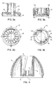
- Fig. 2 ein erstes Teil, der die einseitige Verdrehung bewirkenden Kupplung,
- Fig. 3 das zweite Teil der Kupplung.
- Fig. 4 ein Detail des Gehäuseoberteils
- Der Betätigungsmechanismus besteht aus einem Stössel 11, der in der Oeffnung des Kammerbodens geführt wird. Der Stössel 11 ist fest mit einem Druckknopf 12 verbunden, der nach unten eine zylindrische Verlängerung 13 aufweist, deren äusserer Durchmesser dem Innendurchmesser der Kammer entspricht. Der Druckknopf wird auf diese Weise in der Kammer geführt.
- Zwischen dem Kammerboden und dem Druckknopf befindet sich eine Spiralfeder 14, die den Druckknopf samt Stössel nach oben drückt.
- Auf der Unterseite der zylindrischen Verlängerung des Druckknopfs befindet sich eine zweiteilige Kupplung 15, 16, die nachfolgend genauer beschrieben wird.
- Am unteren Ende des Stössels ist ein Messerhalter 17 befestigt. Zwischen dem Messerhalter 17 und dem Kammerboden befindet sich ein Stossdämpfer 18. Im Messerhalter ist ein an sich bekanntes wellig geformtes Hackmesser 19 befestigt.
- Im Uebrigen ist in an sich bekannter Weise ein Abstreifer 21 vorgesehen, der beim Zerlegen des Gehäuses in Oberteil und Unterteil ebenfalls abgenommen werden kann. Schliesslich befindet sich auf der unteren Seite des Gehäuseunterteils 3 ein Hackteller 22 auf den das Gehäuse aufgesetzt wird.
- Die genaue Ausbildung und Funktion der Kupplung ist aus den Figuren 2 und 3 ersichtlich. Die Kupplung besteht aus zwei Teilen 15, 16, die aber zusammengefügt und gegeneinander verdrehbar sind, allerdings nur in einer Richtung. Der erste Teil 15 ist in Figur 2 gezeigt und zwar in Figur 2a eine Seitenansicht teilweise geschnitten und in Figur 2b eine Aufsicht. Wie aus Figur 2a ersichtlich, besitzt das erste Kupplungsteil 15 eine flache Scheibe 23, die auf ihrer Oberseite mit einseitig angeschrägten und auf der anderen Seite steile Flanken aufweisenden Zähnen 24 versehen ist. Ueber den Umfang der Scheibe 23 sind 16 Zähne verteilt, sodass jedem Zahn ein Winkel von 22,5 Grad entspricht. Auf ihrer äusseren Peripherie besitzt die Scheibe einen zylindrischen Ansatz 25, der mit vier um 90 Grad gegeneinander versetzten zylindrischen Nocken 26 versehen ist. Der Durchmesser dieser Nocken beträgt 3,5 mm und entspricht damit der Breite der spiraligen Nuten 8 in der Kammerwand.
- Auf ihrer Innenseite trägt die Scheibe 23 einen langen, nach oben gerichteten zylindrischen Ansatz 27, dessen Innendurchmesser grösser ist als der Aussendurchmesser des Stössels 11. Der Ansatz 27 besitzt an seiner oberen Seite eine nach oben konisch abgeschrägte Verbreiterung 28, die nach unten einen Anschlag bildet, mit dessen Hilfe die beiden Kupplungsteile zusammengehalten werden. Die Höhe des zylindrischen Ansatzes 27 entspricht der Höhe des nachfolgend zu beschreibenden zweiten Teils der Kupplung.
- Der zweite Teil der Kupplung ist in Figur 3 gezeigt und zwar zeigt Figur 3a eine Kombination aus Schnitt und Ansicht und die Figur 3b einen Grundriss. Es ist zu beachten, dass der Schnitt, den die Figur 3a zeigt, nicht gerade geführt ist, sondern teilweise bogenförmig verläuft. Die Schnittlinie ist in Figur 3b strichpunktiert eingezeichnet.
- Das zweite Kupplungselement 16 besteht im wesentlichen aus einer zylindrischen Aussenwand 29, die mit zwei einander gegenüberliegenden achsparallelen Vorsprüngen 31 versehen ist. Diese Vorsprünge 31 dienen dem Einfügen des zweiten Kupplungsteils 16 in entsprechende Nuten 30 in der Innenwand der Verlängerung des Druckknopfs 12. Einstückig mit der zylindrischen Wand 29 verbunden sind Teile eines Bodens 32, und zwar erstrecken sich diese Teile einander gegenüberliegend jeweils über 90o. An diesen Bodenteilen sind wiederum nach oben gerichtete, ebenfalls einen Winkel von 90o umfassende Ansätze 33 vorgesehen, deren Höhe dem Ansatz des ersten Elements bis zum Anschlag der Verbreiterung entspricht. Der Abstand dieser beiden viertelzylindrischen Ansätze 33 voneinander entspricht dem Aussendurchmesser des Ansatzes des ersten Elements.
- Die Bodenelemente setzen sich jeweils in sich ebenfalls über 90o erstreckende Zungen oder Klinken 34 fort, die nicht mit der Aussenwand 29 verbunden sind und schräg nach unten gerichtet sind. Infolge der Materialeigenschaft haben diese Zungen die Möglichkeit nach oben zu federn. Diese Zungen sind so ausgebildet, dass sie in die steilen Flanken der Zähne 24 eingreifen, wenn die beiden Kupplungsteile zusammengesetzt sind.
- Die Funktion der Kupplung ist wie folgt. Wenn der Druckknopf von Hand nach unten gedrückt wird, wird der untere Teil der Kupplung durch die spiralförmigen Nuten verdreht. Da der Druckknopf aber von der betätigenden Hand festgehalten wird und sich nicht drehen kann, gleitet der obere Kupplungsteil mit den Zungen über die Schrägflächen der Zähne hinweg. Nach dem Loslassen, d.h. bei der Aufwärtsbewegung des Stössels und des Druckknopfes bewirkt der Eingriff der Zungen in die steilen Flanken der Zähne, dass eine gegenseitige Verdrehung der beiden Kupplungsteile nicht mehr möglich ist. Dadurch wird infolge der zwingenden Verdrehung des ersten Kupplungsteils durch die spiralförmigen Nuten auch der Knopf, der Stössel und damit das Messer verdreht. Jede Verdrehung beträgt 22,5 Grad, nach sechzehn Betätigungen ist eine ganze Umdrehung erreicht.
- Als Material für die Vorrichtung kommen die üblichen Kunststoffmaterialien in Frage. Die Kupplung besteht vorzugsweise aus Polyoxymethylen (Delrin (R) ). Selbstverständlich sind andere abriebfeste und die nötigen elastischen Eigenschaften aufweisende Materialien geeignet.
Wie Fig. 1 zeigt, besitzt die Vorrichtung ein Gehäuse 1, das aus einem Oberteil 2 und einem Unterteil 3 besteht. Das Unterteil ist mit dem Oberteil mittels eines Bajonettverschlusses oder dergleichen verbunden. Das Gehäuseoberteil 2 besitzt eine nach oben offene, Kammer, die durch eine mit der Gehäuseaussenwand einstückig verbundene zylindrische Wand 4 und einen Boden 5 gebildet wird. Der Boden 5 besitzt eine von einem zylindrischen Ansatz 6 umgebene Oeffnung 7. Auf ihrer inneren Oberfläche weist die zylindrische Wand spiralig geführte Nuten 8 auf, die aus Fig. 4 ersichtlich sind. Die aus der zylindrischen Wand 4 gebildete Kammer dient der Aufnahme des Betätigungsmechanismus 9.
Claims (2)
- Vorrichtung zum Zerkleinern von Nahrungsmitteln, wie Zwiebeln und dergleichen, mit einem über das zu zerkleinernde Gut stülpbaren Gehäuse (1-3) und einem in dem Gehäuse (1-3) geführten, mittels eines Betätigungsmechanismus (9) mit einem Druckknopf (12) und einem Stössel (11) gegen die Kraft einer Feder (14) nach unten verschiebbaren Messer (19), wobei das Messer (19) bei der Aufwärtsbewegung durch die Führung im Gehäuse (1-3) um einen Winkel verdreht wird, einer Kupplung aus zwei konzentrisch zueinander angeordneten, im wesentlichen ringförmigen Teilen (15, 16), von denen ein Teil (15) auf der dem zweiten Teil (16) zugewandten Stirnfläche über den Umfang verteilt eine Anzahl von einseitig angeschrägten Zähnen aufweist, während das zweite Teil (16) auf der dem ersten zugewandten Stirnfläche zwei oder mehrere federnde und in die senkrechte Flanke der Zähnung (24) eingreifende Zungen (34) aufweist, wobei das eine Kupplungsteil (15) in spiralig geführten Nuten (8) des Gehäuses (1-3) gleitet während das andere Kupplungsteil (16) fest mit dem Betätigungsmechanismus (9) verbunden ist, dadurch gekennzeichnet, dass die genannten Stirnflächen ebene, senkrechte zur Mittelachse der Kupplungsteile (15, 16) stehende Flächen der Kupplungsteile (15, 16) sind und der Eingriff der Zungen (34) in die Zähnung (24) in axialer Richtung erfolgt und dass die beiden Kupplungsteile (15, 16) einsinnig drehbar, in axialer Richtung fest miteinander verbunden sind.
- Vorrichtung nach Anspruch 1, dadurch gekennzeichnet, dass ein fest mit dem Betätigungsmechanismus (9) verbundenes Teil (4) achsparallele Nuten (30) aufweist, in denen das zweite Kupplungsteil (16) mittels an diesem vorhandenen achsparallelen Vorsprüngen (26) gehalten ist.
Applications Claiming Priority (2)
| Application Number | Priority Date | Filing Date | Title |
|---|---|---|---|
| CH2133/88 | 1988-06-03 | ||
| CH213388 | 1988-06-03 |
Publications (2)
| Publication Number | Publication Date |
|---|---|
| EP0345223A1 EP0345223A1 (de) | 1989-12-06 |
| EP0345223B1 true EP0345223B1 (de) | 1994-11-02 |
Family
ID=4226645
Family Applications (1)
| Application Number | Title | Priority Date | Filing Date |
|---|---|---|---|
| EP89810395A Expired - Lifetime EP0345223B1 (de) | 1988-06-03 | 1989-05-29 | Vorrichtung zum Zerkleinern von Nahrungsmitteln |
Country Status (10)
| Country | Link |
|---|---|
| US (1) | US4967970A (de) |
| EP (1) | EP0345223B1 (de) |
| JP (1) | JPH0288198A (de) |
| AT (1) | ATE113518T1 (de) |
| AU (1) | AU605982B2 (de) |
| CA (1) | CA1313483C (de) |
| DE (1) | DE58908581D1 (de) |
| ES (1) | ES2064482T3 (de) |
| HK (1) | HK1006689A1 (de) |
| ZA (1) | ZA894129B (de) |
Cited By (2)
| Publication number | Priority date | Publication date | Assignee | Title |
|---|---|---|---|---|
| EP2364627A1 (de) | 2006-05-04 | 2011-09-14 | SwizzzPROZZZ AG | Gerät zum Bearbeiten von Lebensmitteln |
| US8695490B2 (en) | 2010-04-01 | 2014-04-15 | Columbia Insurance Company | Drive system |
Families Citing this family (42)
| Publication number | Priority date | Publication date | Assignee | Title |
|---|---|---|---|---|
| US5327816A (en) * | 1992-05-05 | 1994-07-12 | Dupont J | Fruit milk shake apparatus |
| ATE175552T1 (de) * | 1995-03-15 | 1999-01-15 | Zyliss Haushaltwaren Ag | Hacker |
| USD380943S (en) * | 1996-02-29 | 1997-07-15 | Hon Nam Wong | Chopper |
| USD378182S (en) * | 1996-04-12 | 1997-02-25 | Wong Yan K | Food chopper |
| USD390745S (en) | 1996-07-24 | 1998-02-17 | Moulinex S.A. | Food chopper |
| USD396992S (en) | 1997-03-19 | 1998-08-18 | Seb | Hand held food processor |
| US5992309A (en) * | 1997-11-26 | 1999-11-30 | General Housewares Corp. | Device for drying foods |
| DE59907709D1 (de) * | 1999-02-11 | 2003-12-18 | Leifheit Ag | Schneidevorrichtung mit einem Abstreifer |
| CA2401512A1 (en) | 2000-02-10 | 2001-08-16 | Moha Moderne Haushaltwaren Ag | Device for chopping foodstuffs |
| ES2215119T3 (es) * | 2001-02-16 | 2004-10-01 | Zyliss Ag | Picadora para triturar productos alimenticios. |
| JP4752023B2 (ja) * | 2001-02-28 | 2011-08-17 | 原田電子工業株式会社 | 部品保持装置 |
| USD464853S1 (en) | 2001-04-27 | 2002-10-29 | Keysun Industrial Co. Ltd. | Chopper |
| USD462881S1 (en) | 2001-08-17 | 2002-09-17 | Wki Holding Company, Inc. | Device for drying food |
| USD481271S1 (en) | 2002-01-11 | 2003-10-28 | Moha Moderne Haushaltwaren Ag | Food chopper |
| US6655032B2 (en) * | 2002-04-30 | 2003-12-02 | Vicki L. Thompson | Pumpkin cutting apparatus |
| USD489585S1 (en) | 2003-01-14 | 2004-05-11 | Hon Ming Wong | Chopper |
| WO2004063647A1 (de) * | 2003-01-15 | 2004-07-29 | Moha Moderne Haushaltwaren Ag | Eishacker |
| EP1462226A1 (de) * | 2003-03-26 | 2004-09-29 | Zyliss AG | Hacker zum Zerkleinern von Lebensmitteln |
| DE10328703B3 (de) * | 2003-06-26 | 2004-11-11 | Leifheit Ag | Schneidvorrichtung |
| US7374114B1 (en) * | 2004-03-08 | 2008-05-20 | Joel Pekay | Device for the destruction of disc media |
| US20050205704A1 (en) * | 2004-03-16 | 2005-09-22 | James Yurchenco | Food chopper |
| US7100854B2 (en) * | 2004-03-18 | 2006-09-05 | Helen Of Troy Limited | Chopper |
| USD515883S1 (en) * | 2004-08-25 | 2006-02-28 | Moha Moderne Haushaltwaren Ag | Chopping device |
| USD518688S1 (en) | 2005-02-23 | 2006-04-11 | Zyliss Usa Corporation | Food chopper |
| WO2007128154A1 (de) | 2006-05-04 | 2007-11-15 | Swizzzprozzz Ag | Gerät zum bearbeiten von lebensmitteln |
| US7744026B2 (en) * | 2006-05-05 | 2010-06-29 | Helen Of Troy Limited | Food mill including a removable blade assembly |
| WO2008096319A1 (en) * | 2007-02-07 | 2008-08-14 | Dalla Piazza & Co. | Pivotally-leveraged manual centrifugal drive |
| US20090114104A1 (en) * | 2007-11-02 | 2009-05-07 | Ravi Kumar Sawhney | Drying Device With Improved Drive Mechanism |
| US7975947B2 (en) * | 2009-11-11 | 2011-07-12 | Emsa Gmbh | Food chopper |
| US8967514B2 (en) * | 2010-03-30 | 2015-03-03 | Johann B. Verheem | Dual food chopper |
| USD651040S1 (en) * | 2011-01-14 | 2011-12-27 | Ibc-Hearthware, Inc. | Mixer |
| US20130043334A1 (en) * | 2011-08-17 | 2013-02-21 | Allan Goldscher | Method and apparatus having a low manufacturing cost for chopping food |
| USD678008S1 (en) * | 2012-02-29 | 2013-03-19 | Lifetime Brands, Inc. | Food chopper |
| US8991734B2 (en) * | 2012-03-09 | 2015-03-31 | Lifetime Brands, Inc. | Food chopper |
| US9622620B2 (en) * | 2012-11-19 | 2017-04-18 | Helen Of Troy Limited | Device for cutting small food items |
| USD717615S1 (en) | 2013-09-04 | 2014-11-18 | Helen Of Troy Limited | Device for cutting small food items |
| US10471617B2 (en) * | 2015-01-26 | 2019-11-12 | Crayola Llc | Pixel art crayon and marker photo array assembly and kit |
| KR101567009B1 (ko) | 2015-07-28 | 2015-11-06 | (주) 테콘 | 식재료 다짐기 |
| CN209610774U (zh) * | 2018-01-10 | 2019-11-12 | 南京盖乐普电子科技有限公司 | 一种杯式榨汁机 |
| WO2021141581A1 (en) * | 2020-01-08 | 2021-07-15 | Macpherson Michael Leland | Box corner cutting device |
| US11202968B1 (en) * | 2020-10-13 | 2021-12-21 | Toy Tech Corp | Hand toy device |
| US11597116B1 (en) * | 2021-09-14 | 2023-03-07 | Progressive International Corp. | Vertical slicer |
Citations (1)
| Publication number | Priority date | Publication date | Assignee | Title |
|---|---|---|---|---|
| DE2719980C3 (de) * | 1977-01-26 | 1979-10-25 | Zyliss Zysset Ag, Lyss (Schweiz) | Schneidvorrichtung zum Zerkleinern von Nahrungsmitteln wie Zwiebeln, Gemüse und Früchte |
Family Cites Families (13)
| Publication number | Priority date | Publication date | Assignee | Title |
|---|---|---|---|---|
| US2140010A (en) * | 1938-03-10 | 1938-12-13 | Hanel Charles Ludwig | Onion chopper |
| CH313138A (de) * | 1953-03-18 | 1956-03-31 | Zysset & Co K | Schneidvorrichtung zum Zerkleinern von Nahrungsmitteln |
| US2787308A (en) * | 1956-07-18 | 1957-04-02 | Samuel J Popeil | Food chopper |
| GB821493A (en) * | 1957-07-16 | 1959-10-07 | Popeil Samuel J | Food chopper |
| US3029851A (en) * | 1958-08-28 | 1962-04-17 | Zysset Karl | Food chopper |
| CH528339A (de) * | 1971-09-13 | 1972-09-30 | Gimelli & Co Ag | Vorrichtung zum Zerkleinern von Nahrungsmitteln, insbesondere Zwiebeln |
| US3933315A (en) * | 1974-07-12 | 1976-01-20 | Popeil Brothers, Inc. | Food chopper & cutting surface |
| CH580479A5 (en) * | 1975-02-07 | 1976-10-15 | Zysset & Co Ag K | Chopper for vegetables, fruit, onions etc. - has open-bottomed housing containing cutting blade attached to pressing handle |
| JPS51122568A (en) * | 1975-04-17 | 1976-10-26 | Ouchi Yoshio | Bag mouth clasp attaching method and apparatus |
| DE2651568C3 (de) * | 1976-11-12 | 1979-04-05 | Gerdes Gmbh & Co, 5830 Schwelm | Schneidvorrichtung zum Zerkleinern von Gartenfrüchten, sogenannter Zwiebelschneider |
| DE7702152U1 (de) * | 1977-01-26 | 1977-05-12 | K. Zysset & Co Ag, Lyss, Bern (Schweiz) | Schneidvorrichtung zum zerkleinern von nahrungsmitteln wie zwiebeln, gemuese und fruechte |
| DE2725923A1 (de) * | 1977-06-08 | 1979-03-08 | Leifheit International | Vorrichtung zum zerkleinern von obst, gemuese, zwiebeln o.dgl. |
| DE2904535C2 (de) * | 1979-02-07 | 1987-03-05 | Leifheit AG, 5408 Nassau | Drehantrieb für eine Schneidvorrichtung zum Zerkleinern von Nahrungsmitteln |
-
1988
- 1988-06-02 US US07/360,358 patent/US4967970A/en not_active Expired - Lifetime
-
1989
- 1989-05-29 AT AT89810395T patent/ATE113518T1/de not_active IP Right Cessation
- 1989-05-29 DE DE58908581T patent/DE58908581D1/de not_active Expired - Lifetime
- 1989-05-29 ES ES89810395T patent/ES2064482T3/es not_active Expired - Lifetime
- 1989-05-29 EP EP89810395A patent/EP0345223B1/de not_active Expired - Lifetime
- 1989-05-31 CA CA000601282A patent/CA1313483C/en not_active Expired - Lifetime
- 1989-05-31 AU AU35857/89A patent/AU605982B2/en not_active Ceased
- 1989-06-01 ZA ZA894129A patent/ZA894129B/xx unknown
- 1989-06-02 JP JP1139399A patent/JPH0288198A/ja active Pending
-
1998
- 1998-06-22 HK HK98105828A patent/HK1006689A1/xx not_active IP Right Cessation
Patent Citations (1)
| Publication number | Priority date | Publication date | Assignee | Title |
|---|---|---|---|---|
| DE2719980C3 (de) * | 1977-01-26 | 1979-10-25 | Zyliss Zysset Ag, Lyss (Schweiz) | Schneidvorrichtung zum Zerkleinern von Nahrungsmitteln wie Zwiebeln, Gemüse und Früchte |
Cited By (4)
| Publication number | Priority date | Publication date | Assignee | Title |
|---|---|---|---|---|
| EP2364627A1 (de) | 2006-05-04 | 2011-09-14 | SwizzzPROZZZ AG | Gerät zum Bearbeiten von Lebensmitteln |
| US8695490B2 (en) | 2010-04-01 | 2014-04-15 | Columbia Insurance Company | Drive system |
| US9089243B2 (en) | 2010-04-01 | 2015-07-28 | Columbia Insurance Company | Drive system for household implements including food processor |
| US9964188B2 (en) | 2010-04-01 | 2018-05-08 | Columbia Insurance Company | Drive system |
Also Published As
| Publication number | Publication date |
|---|---|
| CA1313483C (en) | 1993-02-09 |
| AU3585789A (en) | 1989-12-07 |
| ZA894129B (en) | 1990-02-28 |
| DE58908581D1 (de) | 1994-12-08 |
| US4967970A (en) | 1990-11-06 |
| ATE113518T1 (de) | 1994-11-15 |
| ES2064482T3 (es) | 1995-02-01 |
| JPH0288198A (ja) | 1990-03-28 |
| EP0345223A1 (de) | 1989-12-06 |
| AU605982B2 (en) | 1991-01-24 |
| HK1006689A1 (en) | 1999-03-12 |
Similar Documents
| Publication | Publication Date | Title |
|---|---|---|
| EP0345223A1 (de) | Vorrichtung zum Zerkleinern von Nahrungsmitteln | |
| EP1253997B1 (de) | Vorrichtung zum zerkleinern von nahrungsmitteln | |
| DE2141813C3 (de) | Gerät für die Zubereitung von Nahrungsmitteln | |
| EP0975456B1 (de) | Knoblauchschneider | |
| DE3136325A1 (de) | Klappmesser | |
| DE69912906T2 (de) | Zerkleinerungsvorrichtung für getrocknete Gewürze und Kräuter | |
| EP0967056A2 (de) | Knoblauchschneider | |
| DE10223075A1 (de) | Gemüseschneider | |
| DE1021333B (de) | Spaltfilter für Flüssigkeiten | |
| EP0261617A2 (de) | Dosierspender | |
| DE2651568A1 (de) | Schneidvorrichtung zum zerkleinern von gartenfruechten, sogenannter zwiebelschneider | |
| DE2116675A1 (de) | ||
| DE2164361B2 (de) | Reibgerät für Lebensmittel | |
| EP0196550B1 (de) | Halter zum Handhaben von auf Küchengeräten zu zerkleinernden Früchten | |
| DE60305074T2 (de) | Küchenmaschine mit werkzeugen kombiniert zu einer werkzeugeinheit | |
| CH619665A5 (en) | Container with lid | |
| EP0032555A1 (de) | Zähl- oder Druckwerk zum fortlaufenden Zählen oder Numerieren | |
| EP0037021A1 (de) | Haltevorrichtung für ein rotierendes zahnärztliches Werkzeug | |
| DE10307930A1 (de) | Handmühle, insbesondere zur Zerkleinerung von Pfeffer | |
| DE1665800B2 (de) | Drehschalterantrieb | |
| DE2838946C3 (de) | Dosierbehälter für pulverförmige oder körnige Stoffe | |
| DE3220449A1 (de) | Kuechenmaschine mit motorischem antrieb | |
| DE3516644A1 (de) | Permutationsschloss fuer koffer oder dergleichen | |
| EP0217190B1 (de) | Vorrichtung zum Knacken oder Zerdrücken von Nüssen | |
| DE29917567U1 (de) | Mühle für rieselfähiges Mahlgut, insbesondere Kaffee |
Legal Events
| Date | Code | Title | Description |
|---|---|---|---|
| PUAI | Public reference made under article 153(3) epc to a published international application that has entered the european phase |
Free format text: ORIGINAL CODE: 0009012 |
|
| AK | Designated contracting states |
Kind code of ref document: A1 Designated state(s): AT BE CH DE ES FR GB GR IT LI LU NL SE |
|
| 17P | Request for examination filed |
Effective date: 19900205 |
|
| 17Q | First examination report despatched |
Effective date: 19910311 |
|
| GRAA | (expected) grant |
Free format text: ORIGINAL CODE: 0009210 |
|
| AK | Designated contracting states |
Kind code of ref document: B1 Designated state(s): AT BE CH DE ES FR GB GR IT LI LU NL SE |
|
| PG25 | Lapsed in a contracting state [announced via postgrant information from national office to epo] |
Ref country code: GR Free format text: LAPSE BECAUSE OF FAILURE TO SUBMIT A TRANSLATION OF THE DESCRIPTION OR TO PAY THE FEE WITHIN THE PRESCRIBED TIME-LIMIT Effective date: 19941102 |
|
| REF | Corresponds to: |
Ref document number: 113518 Country of ref document: AT Date of ref document: 19941115 Kind code of ref document: T |
|
| REF | Corresponds to: |
Ref document number: 58908581 Country of ref document: DE Date of ref document: 19941208 |
|
| GBT | Gb: translation of ep patent filed (gb section 77(6)(a)/1977) |
Effective date: 19941207 |
|
| ITF | It: translation for a ep patent filed | ||
| ET | Fr: translation filed | ||
| REG | Reference to a national code |
Ref country code: ES Ref legal event code: FG2A Ref document number: 2064482 Country of ref document: ES Kind code of ref document: T3 |
|
| PG25 | Lapsed in a contracting state [announced via postgrant information from national office to epo] |
Ref country code: SE Effective date: 19950202 |
|
| PLBE | No opposition filed within time limit |
Free format text: ORIGINAL CODE: 0009261 |
|
| STAA | Information on the status of an ep patent application or granted ep patent |
Free format text: STATUS: NO OPPOSITION FILED WITHIN TIME LIMIT |
|
| 26N | No opposition filed | ||
| REG | Reference to a national code |
Ref country code: CH Ref legal event code: NV Representative=s name: PATENTANWALTSBUERO FELDMANN AG |
|
| REG | Reference to a national code |
Ref country code: GB Ref legal event code: IF02 |
|
| PGFP | Annual fee paid to national office [announced via postgrant information from national office to epo] |
Ref country code: AT Payment date: 20050525 Year of fee payment: 17 |
|
| PG25 | Lapsed in a contracting state [announced via postgrant information from national office to epo] |
Ref country code: AT Free format text: LAPSE BECAUSE OF NON-PAYMENT OF DUE FEES Effective date: 20060529 |
|
| PGFP | Annual fee paid to national office [announced via postgrant information from national office to epo] |
Ref country code: FR Payment date: 20060529 Year of fee payment: 18 |
|
| PGFP | Annual fee paid to national office [announced via postgrant information from national office to epo] |
Ref country code: ES Payment date: 20060530 Year of fee payment: 18 |
|
| PGFP | Annual fee paid to national office [announced via postgrant information from national office to epo] |
Ref country code: BE Payment date: 20060531 Year of fee payment: 18 Ref country code: IT Payment date: 20060531 Year of fee payment: 18 |
|
| PGFP | Annual fee paid to national office [announced via postgrant information from national office to epo] |
Ref country code: NL Payment date: 20060614 Year of fee payment: 18 |
|
| PGFP | Annual fee paid to national office [announced via postgrant information from national office to epo] |
Ref country code: LU Payment date: 20060615 Year of fee payment: 18 |
|
| REG | Reference to a national code |
Ref country code: CH Ref legal event code: PFA Owner name: MOHA MODERNE HAUSHALTWAREN AG Free format text: MOHA MODERNE HAUSHALTWAREN AG#TANNHOLZSTRASSE 14#3052 ZOLLIKOFEN (CH) -TRANSFER TO- MOHA MODERNE HAUSHALTWAREN AG#TANNHOLZSTRASSE 14#3052 ZOLLIKOFEN (CH) |
|
| BERE | Be: lapsed |
Owner name: MODERNE HAUSHALTWAREN A.G. *MOHA Effective date: 20070531 |
|
| PG25 | Lapsed in a contracting state [announced via postgrant information from national office to epo] |
Ref country code: NL Free format text: LAPSE BECAUSE OF NON-PAYMENT OF DUE FEES Effective date: 20071201 |
|
| NLV4 | Nl: lapsed or anulled due to non-payment of the annual fee |
Effective date: 20071201 |
|
| REG | Reference to a national code |
Ref country code: FR Ref legal event code: ST Effective date: 20080131 |
|
| PG25 | Lapsed in a contracting state [announced via postgrant information from national office to epo] |
Ref country code: BE Free format text: LAPSE BECAUSE OF NON-PAYMENT OF DUE FEES Effective date: 20070531 |
|
| PG25 | Lapsed in a contracting state [announced via postgrant information from national office to epo] |
Ref country code: FR Free format text: LAPSE BECAUSE OF NON-PAYMENT OF DUE FEES Effective date: 20070531 |
|
| REG | Reference to a national code |
Ref country code: ES Ref legal event code: FD2A Effective date: 20070530 |
|
| PG25 | Lapsed in a contracting state [announced via postgrant information from national office to epo] |
Ref country code: ES Free format text: LAPSE BECAUSE OF NON-PAYMENT OF DUE FEES Effective date: 20070530 |
|
| PGFP | Annual fee paid to national office [announced via postgrant information from national office to epo] |
Ref country code: DE Payment date: 20080710 Year of fee payment: 20 Ref country code: CH Payment date: 20080826 Year of fee payment: 20 |
|
| PGFP | Annual fee paid to national office [announced via postgrant information from national office to epo] |
Ref country code: GB Payment date: 20080722 Year of fee payment: 20 |
|
| REG | Reference to a national code |
Ref country code: CH Ref legal event code: PL |
|
| REG | Reference to a national code |
Ref country code: GB Ref legal event code: PE20 Expiry date: 20090528 |
|
| PG25 | Lapsed in a contracting state [announced via postgrant information from national office to epo] |
Ref country code: LU Free format text: LAPSE BECAUSE OF NON-PAYMENT OF DUE FEES Effective date: 20070529 |
|
| PG25 | Lapsed in a contracting state [announced via postgrant information from national office to epo] |
Ref country code: IT Free format text: LAPSE BECAUSE OF NON-PAYMENT OF DUE FEES Effective date: 20070529 |
|
| PG25 | Lapsed in a contracting state [announced via postgrant information from national office to epo] |
Ref country code: GB Free format text: LAPSE BECAUSE OF EXPIRATION OF PROTECTION Effective date: 20090528 |