EP0339323B1 - Elektro-Staubsauger - Google Patents
Elektro-Staubsauger Download PDFInfo
- Publication number
- EP0339323B1 EP0339323B1 EP89106043A EP89106043A EP0339323B1 EP 0339323 B1 EP0339323 B1 EP 0339323B1 EP 89106043 A EP89106043 A EP 89106043A EP 89106043 A EP89106043 A EP 89106043A EP 0339323 B1 EP0339323 B1 EP 0339323B1
- Authority
- EP
- European Patent Office
- Prior art keywords
- filter bag
- vacuum cleaner
- electric vacuum
- chamber
- cleaner according
- Prior art date
- Legal status (The legal status is an assumption and is not a legal conclusion. Google has not performed a legal analysis and makes no representation as to the accuracy of the status listed.)
- Expired - Lifetime
Links
- 210000003128 head Anatomy 0.000 claims description 16
- 238000007789 sealing Methods 0.000 claims description 5
- 238000001746 injection moulding Methods 0.000 claims 2
- 238000000926 separation method Methods 0.000 abstract description 2
- 238000007765 extrusion coating Methods 0.000 description 7
- 239000000463 material Substances 0.000 description 7
- 238000005538 encapsulation Methods 0.000 description 4
- 239000004753 textile Substances 0.000 description 4
- 230000006835 compression Effects 0.000 description 3
- 238000007906 compression Methods 0.000 description 3
- 239000000428 dust Substances 0.000 description 3
- 210000002105 tongue Anatomy 0.000 description 3
- 230000007704 transition Effects 0.000 description 3
- 241001295925 Gegenes Species 0.000 description 2
- 230000008901 benefit Effects 0.000 description 2
- 238000007664 blowing Methods 0.000 description 2
- 230000008878 coupling Effects 0.000 description 2
- 238000010168 coupling process Methods 0.000 description 2
- 238000005859 coupling reaction Methods 0.000 description 2
- 238000011161 development Methods 0.000 description 2
- 230000018109 developmental process Effects 0.000 description 2
- 230000000694 effects Effects 0.000 description 2
- 230000002349 favourable effect Effects 0.000 description 2
- 238000003780 insertion Methods 0.000 description 2
- 230000037431 insertion Effects 0.000 description 2
- 239000002245 particle Substances 0.000 description 2
- 230000009471 action Effects 0.000 description 1
- 239000011324 bead Substances 0.000 description 1
- 230000015572 biosynthetic process Effects 0.000 description 1
- 230000000903 blocking effect Effects 0.000 description 1
- 230000008859 change Effects 0.000 description 1
- 230000006378 damage Effects 0.000 description 1
- 230000007423 decrease Effects 0.000 description 1
- 238000005516 engineering process Methods 0.000 description 1
- 239000006260 foam Substances 0.000 description 1
- 239000006261 foam material Substances 0.000 description 1
- 238000004519 manufacturing process Methods 0.000 description 1
- 238000000034 method Methods 0.000 description 1
- 239000010813 municipal solid waste Substances 0.000 description 1
- IHQKEDIOMGYHEB-UHFFFAOYSA-M sodium dimethylarsinate Chemical class [Na+].C[As](C)([O-])=O IHQKEDIOMGYHEB-UHFFFAOYSA-M 0.000 description 1
- 239000007779 soft material Substances 0.000 description 1
Images


Classifications
-
- A—HUMAN NECESSITIES
- A47—FURNITURE; DOMESTIC ARTICLES OR APPLIANCES; COFFEE MILLS; SPICE MILLS; SUCTION CLEANERS IN GENERAL
- A47L—DOMESTIC WASHING OR CLEANING; SUCTION CLEANERS IN GENERAL
- A47L9/00—Details or accessories of suction cleaners, e.g. mechanical means for controlling the suction or for effecting pulsating action; Storing devices specially adapted to suction cleaners or parts thereof; Carrying-vehicles specially adapted for suction cleaners
- A47L9/10—Filters; Dust separators; Dust removal; Automatic exchange of filters
- A47L9/14—Bags or the like; Rigid filtering receptacles; Attachment of, or closures for, bags or receptacles
- A47L9/1427—Means for mounting or attaching bags or filtering receptacles in suction cleaners; Adapters
- A47L9/1436—Connecting plates, e.g. collars, end closures
Definitions
- the invention relates to an electric vacuum cleaner with a chamber arranged above its motor fan for receiving a filter bag, which is connected to the connection port to a filter bag intermediate carrier which is dragged along when the chamber is opened and which has a valve closure body, and of which the valve bag is approximately beyond the vertical position of the Port connection cross-sectional plane is separable.
- An electric vacuum cleaner of this type is known from EP-A-0 289 709 (not previously published). It has a chamber arranged above its rotor blower for receiving a filter bag, which is connected to the nozzle connection to a filter bag intermediate carrier which is carried along when the chamber is opened and which has a valve closure body, and from which the filter bag can be separated approximately beyond the vertical position of the nozzle connection cross-sectional plane.
- the object of the invention is to improve a generic electric vacuum cleaner in terms of handling, especially in terms of production technology, in such a way that clean, convenient removal of the filled filter bag is provided.
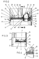
- the electric vacuum cleaner shown is designed as a handheld device. It has a housing 1, to which a handle 2 is connected at the top with an end handle 3. In the transition area between handle 3 and handle 2 there is an on / off switch 4. The electrical cable connection is not shown.
- the housing 1 is subdivided into a motor housing 5 and a chamber 6 extending thereon for receiving a filter bag 7.
- the motor fan is also not shown in detail in the drawing.
- the side of the filter bag 7 facing the motor housing 5 is in the connection connection V to the blower air duct 8.
- the underside of the motor housing 5 merges into a pipe coupling 9, which establishes the air flow connection to a suction nozzle 10.
- the suction nozzle 10 can be a so-called suction / brush nozzle, which contains a brush roller in the nozzle mouth, which is set in rotation by a separate drive.
- the blower motor thus works from the bottom up, consequently pushes the dust air into the filter bag 7, which is arranged to fall above the motor housing 5.
- the cross section of the housing 1 is generally rectangular with slightly bulging broad sides and narrow sides. In Figure 1, the vacuum cleaner can be seen from the broad side.
- the chamber 6 receiving the cross section corresponding to the filter bag 7 is formed by a wire basket stiffened textile bag 11 which at the bottom, i.e. merges into a stiffened edge in the form of a chamber connector 12 on the motor housing side.
- the stiffened textile bag 11 can be assigned to this chamber connector 12 by means of the detachable clip plug connection.
- the plug-on area is set apart.
- the stage can be seen in Fig. 1. It allows a defined interior or exterior assignment of the textile sack. An internal plug assignment is preferred.
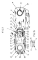
- the housing 1 can be opened practically with its cross-section completely released.
- the opening position results from FIG. 1 (here in dash-dotted lines) and 5, 7.
- the folding axis 14 which enables this is located on one narrow side of the housing 1.
- Their bearing eyes on the chamber neck are designated by 15. These bearing eyes are located at the transition area between the narrow side and the broad side of the chamber 6.
- a continuous bearing eye of the motor housing 5 extends between the two bearing eyes 15.
- an intermediate carrier T is also integrated, on which the filter bag 7 is seated.
- the filter bag intermediate carrier T has a floor plan adapted to the cross section of the housing, but emerges from the outer wall of the housing, so that it is essentially completely hidden from view in the coaxial position of the motor housing 5 and chamber 6 shown in FIG. 1. Except for a small access point, it is grasped by the flared, lower edge of the chamber connector 12 of the filter bag intermediate carrier T, which is also foldable, and folds about the same folding axis 14 as the filter bag chamber 6.
- the intermediate carrier T therefore also forms the hinge side, as is the case with also the chamber connector 12, two bearing eyes, which are designated 16 here.
- the filter bag 7 directly adjoining the intermediate carrier T has a bottom 17. Its general outline also corresponds to the cross-sectional shape of the chamber connector 12, which forms an edge step 18 on the inner wall for support purposes in the region of the narrow sides of the bottom 17. As a result, the bottom 17 cannot slide into the chamber 6 in the opened position of the device.
- the bridge-shaped support of the base 17, on the other hand, brings about a certain flexibility of the base in the central region.
- the common folding axis 14 of the chamber connector 12 and the filter bag intermediate carrier T extends approximately at the level of the support edge step 18 of the filter bag base 17 Housing (Fig. 2) overlaps the edge step the top of said bottom 17 so that it is not lifted upward during suction blowing.
- the bottom of the bottom 17 rests, as already indicated, on the top of the filter bag intermediate carrier T. In the areas of the narrow side of the bottom 17 there is a type of clamping jaw border between the chamber connector 12 and the intermediate carrier T.
- blower air duct 8 projects with its stepped, cylindrical mouth end 8 'into the lower region of a connecting piece 19.
- the latter protrudes above the upper side of the filter bag intermediate carrier T.
- the connecting piece 19 is molded onto the intermediate carrier T and, projecting through an opening 20 of the filter bag base 17 corresponding to a cross-section, extends into the interior of the filter bag 7.
- the connector 19 forms a valve flap 21 at its free end.
- the latter lies freely with the predominant edge area on the front edge of the connector 19. It is only fixed at the point designated 22, so that it lifts off under the action of the air flow, but returns to its closed position when the corresponding underside load decreases.
- the valve flap 21 can be created as a separate component and assigned to the location 22 by means of the clip assignment; alternatively, of course, there is the possibility of forming with a correspondingly flexible material of the connector 19 or filter bag intermediate carrier T.
- the nozzle 19 tapers towards its free end, so that its insertion into the opening 20 has a practically centering effect.
- the front edge is chamfered. It slopes in the direction of the folding axis 14. A line in this direction intersects the folding axis.
- the connection point 22 is located in the higher area of the nozzle edge.
- the socket 19 takes a radial curvature to the axis 14. Between the root region of the socket 19 and the area on the folding axis side, the intermediate carrier T is broken like a window.
- the hinge-side frame leg has a greater width than the two frame legs facing the broad side wall of the housing.
- the intermediate carrier T forms a freely accessible handle 24 on its end face there. It is an underside angular extension. This arises from an area that springs back relative to the end face 25 there.
- the relevant leg runs vertically.
- the adjoining, essentially horizontal leg runs back to the casing wall of the housing and closes with it at the same level.
- a hook-type latching device which secures the closed position of the housing and can be actuated by a pushbutton, and is not shown.
- the corresponding zone of the motor housing 5 is recessed like a niche. The recess bears the reference number 26.
- cams 27 point upward in the region of the longer frame legs of the intermediate carrier.
- the latter close gripping openings 28 on the longer side marginal edges of the filter bag base 17.
- Both gripping openings 28 are chamfered and open towards the corresponding inner wall of the chamber connector. In the open position of the housing 1 can be conveniently gripped by the tensioning handle of the wasp waist-like central zone of the bottom 17 of the filter bag and lifted out of the chamber 6.
- the filter bag intermediate carrier T is assigned and designed such that it passes through a limited swivel angle, ie cannot reach the 180 ° angular position of the chamber connector 12; Rather, it remains in the position which is approximately in or beyond the vertical position EE of the nozzle connection cross-sectional plane, so that the nozzle connection connection V is already beyond the bisector of the maximum swivel range of 180 °. In this position there is enough space for the filter bag 7 to pull it away from the intermediate carrier.
- the transition to the position reversed to the lintel position, that is to say opening 20 pointing upwards, takes place without the possibility of escape of dust or larger particles.
- the filter bag can therefore be comfortably gripped and lifted in the manner explained above or after removing the chamber.
- the bag wall is not pushed in. There is no need to touch its wall when it is removed; there is no blowing out. By stretching the bag there is at most a suction effect.
- the insertion of a new filter bag is very simple in the same way, since the chamber with its entire cross-section is open at the top (see FIG. 1). It is then only necessary to swivel the chamber 6 back into the position shown in solid lines in FIG. 1, in which the superstructure of the housing 1 comprising the chamber 6 automatically locks onto the motor housing 5. On this fold-back path, the opening 20 catches the socket 19 or vice versa. This can take place in the vertical position of the filter bag intermediate carrier T, which may still be frictionally engaged, or only when the back of the filter carrier T rests on the top of the motor housing 5. In the closed position, the cams 27 fill the Gripping openings 28 again largely, that is, so far that there can be no protuberances of the fleece-like paper filter wall 31 when the filter bag swells or due to the filling load.
- orientation features 32 are trapezoidal projections on the narrow side of the plate-like body forming the bottom 17. In this way, an alignment-appropriate position between opening 20 and connecting piece 19 is achieved before a misassignment is noticeable only when the housing parts do not come together properly.
- the mutually facing longitudinal sides 27 'of the cams 27 are rounded transversely, which also serves for the correct assignment of the base 17. They act like control surfaces on the corresponding rounded niche base of the gripping openings 28.
- tongues 32a, 32b and 32c are provided at an angle symmetry to the opening.
- the side edge tongues 32b and 32c run obliquely into the gripping openings. They are covered on the top with foam Sch, which forms a sealing ring zone of the hole 20.
- the folded edges K of the wall (paper) of the filter bag held against the underside of the base 17 cross the gripping openings and are exceeded by the tongues 32b and 32c.
- the chamber or the chamber connector 12 can be disengaged from the folding axis 14. You are able to do that full filter bag 7 containing chamber convenient to carry trash can or the like. In addition, the chamber 6 and the wire-head-stiffened textile bag 11 can be cleaned comfortably from time to time without the whole device hanging on it.
- connection point on the chamber nozzle side is a molded housing-like projection 12 'which projects into the region of the axis 14 and which extends practically congruently with the bearing eyes 15 fixed to the housing and the axle bearing eyes 16 of the filter bag intermediate carrier T.
- the latching means are formed by pins 50 which are sprung against one another and outwards. The latter protrude beyond the end face of the projection 12 '.
- This protruding section is designed as a beveled trap head 51.
- the slant of the trap has the reference symbol 52.
- the trap heads 51 have a flattened cross-section and interact with the journal journals 16 of the intermediate carrier T lying in front of them. These bearing eyes 16 each form a radial slot 53 which is open towards the outside.
- the radial slot 53 widens outwards in a funnel shape.
- the funnel shape favors centering on the axis center line, but also forms a run-up flank 54 corresponding to the helix angle of the trap slope 52.
- the inverse end of the run-up flank 54 then continues in a transverse shoulder 55 which is latched under by the back of the trap slope.
- the locking shoulder 55 is the partial wall area of a receiving cavity 56 for the latch head 51 of the axle journal bearing eyes 16.
- the narrowest width of the radial slot 53 corresponds to the flattening width of the latch heads 51.
- compression spring 57 it is a helical compression spring.
- the pins 50 are secured against rotation. For this purpose they have longitudinal ribs 58 which engage in contour-corresponding longitudinal grooves 59 of the receptacles of the projections 12 '. The inward ends of the pins 50 have stops so that the pins 50 do not jump out of their housing despite spring loading.
- the latch heads 51 adopt a blocking alignment with the corresponding journal journals 16.
- 10 to 12 also show a different design of the swivel limit stop for the intermediate carrier T, in that the axle journal bearing eyes 16 come against a shoulder 61 on the housing side with a radial stop lug 60.
- the actual axis 14 is formed by stub axles 14 ′ formed in the back of the receiving cavity 56 for the latch head 51 the journal bearing eyes 16 formed. These protrude into corresponding cavities in the bearing eyes 15 of the housing.
- the receiving cavity 56 is enlarged in the manner of an elongated hole in the direction of the plane of extent of the intermediate carrier T.
- the intermediate carrier T is equipped with an extrusion coating U.
- This encapsulation consists of a somewhat softer material than that of the intermediate carrier T.
- the encapsulation extends at least on the edge side, so that not only the narrow end edge of the plate-shaped intermediate carrier T is covered, but also the top and bottom of the intermediate carrier.
- the flexible material not only provides an edge seal between the bottom 17 of the filter bag 7, but also to the ceiling of the motor housing 5.
- the material of the extrusion coating U is also drawn into the area of the connector 19 of the intermediate carrier T by surrounding this connector 19 in a jacket-like manner.
- the corresponding change of sides towards the top of the intermediate carrier is provided by an edge perforation in the foot region of the connector 19.
- the openings are designated 63 and can be seen in FIG. 22.
- the extrusion coating forms a sealing lip 64 which projects into the stepped blower air duct.
- the sealing lip 64 is tapered in a funnel shape on the channel side.
- the overmolding also forms the cams 27 explained above, which protrude into the gripping openings 28 of the bottom 17 of the filter bag.
- the relatively soft material also has sufficient suppleness so that there is no forced coupling.
- the cams 27 are formed by high-angled wall sections of the encapsulation material (rubber or plastic), which wall sections have a curvature running in the longitudinal direction or only end at the ends in curvature sections, so that the desired stability is present despite the softness.
- the edge of the chamber connector 12 on the filter base tips out in a cutting-like manner (cf. FIG. 4).
- the filter bag base 17 is overlapped by at least two lugs 65 lying on both sides of the opening 20 of the base 17.
- the overlap is, as can be seen from FIG. 15, very small, so that the filter bag can be lifted out at the bottom 17 with a will-oriented pull.
- Injection-free zones are only taken into account in the area of the exit of the journal journals 16 and in the area of the handle 25.
- the mouth edge of the opening 20 of the base 17 is lined on the carrier side by an elastic layer 66. This extends in the vicinity of the opening 20 to the periphery of the floor. It can be foam material.
- the extrusion coating U is used to form the valve flap 21. It is a blanket covering the mouth of the nozzle, which is cut all around except for the hinge point 22.
Landscapes
- Engineering & Computer Science (AREA)
- Mechanical Engineering (AREA)
- Filters For Electric Vacuum Cleaners (AREA)
- Measurement And Recording Of Electrical Phenomena And Electrical Characteristics Of The Living Body (AREA)
- Saccharide Compounds (AREA)
- External Artificial Organs (AREA)
- Solid-Sorbent Or Filter-Aiding Compositions (AREA)
- Filtering Materials (AREA)
- Electrostatic Separation (AREA)
Priority Applications (3)
| Application Number | Priority Date | Filing Date | Title |
|---|---|---|---|
| AT89106043T ATE91864T1 (de) | 1988-04-29 | 1989-04-06 | Elektro-staubsauger. |
| EP92116903A EP0532057B1 (de) | 1988-04-29 | 1989-04-06 | Filterbeutel |
| GR970402948T GR3025306T3 (en) | 1988-04-29 | 1997-11-07 | Dust bag |
Applications Claiming Priority (2)
| Application Number | Priority Date | Filing Date | Title |
|---|---|---|---|
| IT1246288 | 1988-04-29 | ||
| IT12462/88A IT1220563B (it) | 1987-05-04 | 1988-04-29 | Aspirapolvere elettrico |
Related Child Applications (1)
| Application Number | Title | Priority Date | Filing Date |
|---|---|---|---|
| EP92116903.3 Division-Into | 1989-04-06 |
Publications (3)
| Publication Number | Publication Date |
|---|---|
| EP0339323A2 EP0339323A2 (de) | 1989-11-02 |
| EP0339323A3 EP0339323A3 (en) | 1990-12-12 |
| EP0339323B1 true EP0339323B1 (de) | 1993-07-28 |
Family
ID=11140447
Family Applications (1)
| Application Number | Title | Priority Date | Filing Date |
|---|---|---|---|
| EP89106043A Expired - Lifetime EP0339323B1 (de) | 1988-04-29 | 1989-04-06 | Elektro-Staubsauger |
Country Status (11)
| Country | Link |
|---|---|
| US (1) | US4961765A (es) |
| EP (1) | EP0339323B1 (es) |
| JP (1) | JP2907865B2 (es) |
| AT (1) | ATE158158T1 (es) |
| AU (1) | AU3381089A (es) |
| CA (1) | CA1326333C (es) |
| DE (3) | DE58909817D1 (es) |
| ES (2) | ES2106808T3 (es) |
| FI (1) | FI86592C (es) |
| LV (1) | LV10680B (es) |
| ZA (1) | ZA893195B (es) |
Families Citing this family (27)
| Publication number | Priority date | Publication date | Assignee | Title |
|---|---|---|---|---|
| IT221843Z2 (it) * | 1991-04-24 | 1994-12-06 | Vorwerk Co Interholding | Sacchetto filtropolvere |
| DE9109522U1 (de) * | 1991-08-01 | 1991-10-17 | Vorwerk & Co Interholding Gmbh, 5600 Wuppertal | Filterbeutelzwischenträger |
| DE4141598C2 (de) * | 1991-12-17 | 1994-12-08 | Licentia Gmbh | Staubsauger-Staubbeutelführung |
| US5448794A (en) * | 1993-09-16 | 1995-09-12 | Electrolux Corporation | Corded handheld vacuum cleaner |
| DE9318142U1 (de) * | 1993-11-26 | 1995-03-30 | Vorwerk & Co Interholding Gmbh, 42275 Wuppertal | Elektro-Staubsauger mit einer Aufnahmekammer für einen Staubbeutel |
| DE4341248C2 (de) * | 1993-12-03 | 2003-04-30 | Vorwerk Co Interholding | Staubfilterbeutel für einen Staubsauger |
| CZ294417B6 (cs) * | 1993-12-03 | 2004-12-15 | Vorwerk & Co. Interholding Gmbh | Filtrační sáček na prach pro vysavač prachu |
| FI1987U1 (fi) * | 1995-01-30 | 1995-07-06 | Sisko Tuulikki Mussalo | Hjaelputrustning vid dammsugare |
| AU5894296A (en) * | 1995-06-06 | 1996-12-24 | Vorwerk & Co. Interholding Gmbh | Vacuum cleaner with a dust filter bag |
| US5688298A (en) * | 1995-10-10 | 1997-11-18 | Home Care Industries, Inc. | Self-aligning, self-sealing vacuum bag |
| US5613989A (en) * | 1995-10-10 | 1997-03-25 | Home Care Industries, Inc. | Self-aligning self-sealing vacuum bag |
| DE19612935B4 (de) * | 1996-04-01 | 2006-05-11 | Vorwerk & Co. Interholding Gmbh | Staubsauger mit einem Staubsauger-Gehäuse |
| US6314610B1 (en) * | 1999-04-23 | 2001-11-13 | The Hoover Company | Vacuum cleaner bag housing assembly |
| US6179889B1 (en) | 1999-07-07 | 2001-01-30 | Shop Vac Corporation | Vacuum cleaner tank assembly |
| US7143469B2 (en) * | 2001-02-06 | 2006-12-05 | The Hoover Company | Dirt collecting system |
| USD481182S1 (en) | 2001-05-09 | 2003-10-21 | The Hoover Company | Vacuum cleaner dirt receptacle lid |
| US7468083B2 (en) * | 2003-11-07 | 2008-12-23 | Panasonic Corporation Of North America | Vacuum cleaner equipped with bag mount and separate bag caddy |
| US20090089966A1 (en) * | 2007-10-08 | 2009-04-09 | Ian Emil Sohn | Vacuum Cleaner Bag Mounting Structure |
| CN103519748A (zh) * | 2013-09-18 | 2014-01-22 | 侯赢 | 一种负压粮油饲料专用吸尘器 |
| USD779674S1 (en) | 2015-02-27 | 2017-02-21 | 3M Innovative Properties Company | Filter element having a connector |
| BR112017018381B1 (pt) | 2015-02-27 | 2022-01-25 | 3M Innovative Properties Company | Elementos filtrantes flexíveis tendo uma saída de extremidade |
| USD792959S1 (en) | 2015-02-27 | 2017-07-25 | 3M Innovative Properties Company | Filter element having a pattern |
| USD786443S1 (en) | 2015-02-27 | 2017-05-09 | 3M Innovative Properties Company | Filter element |
| FI3884833T3 (fi) | 2016-05-09 | 2024-10-09 | Electrolux Ab | Pölysäiliö imuria varten |
| GB2598506B (en) | 2017-06-19 | 2022-06-08 | Techtronic Floor Care Tech Ltd | A dirt separation device |
| US10842334B2 (en) * | 2018-05-04 | 2020-11-24 | Irobot Corporation | Filtering devices for evacuation stations |
| CN217096845U (zh) * | 2018-08-31 | 2022-08-02 | 米沃奇电动工具公司 | 电动工具 |
Family Cites Families (9)
| Publication number | Priority date | Publication date | Assignee | Title |
|---|---|---|---|---|
| US2360155A (en) * | 1942-10-01 | 1944-10-10 | Air Way Electric Appl Corp | Suction cleaner |
| US2564468A (en) * | 1946-02-15 | 1951-08-14 | Electrolux Corp | Vacuum cleaner |
| DE2719397A1 (de) * | 1977-04-30 | 1978-11-02 | Licentia Gmbh | Staubsauger |
| DE7832780U1 (de) * | 1978-11-04 | 1979-03-01 | Vorwerk & Co Interholding Gmbh, 5600 Wuppertal | Halteplatte fuer staubsaugerfilterbeutel |
| DE8132286U1 (de) * | 1981-11-05 | 1982-04-15 | Vorwerk & Co Interholding Gmbh, 5600 Wuppertal | Handstaubsauger |
| DE8320697U1 (de) * | 1983-07-19 | 1983-11-03 | Vorwerk & Co Interholding Gmbh, 5600 Wuppertal | Filterkassette fuer handstaubsauger |
| EP0289709B1 (de) * | 1987-05-04 | 1991-07-17 | Vorwerk & Co. Interholding GmbH | Elektro-Staubsauger |
| DE3714773A1 (de) * | 1987-05-04 | 1988-12-01 | Vorwerk Co Interholding | Anorndung von filterbeuteln in elektro-staubsaugern |
| DE3714780A1 (de) * | 1987-05-04 | 1988-12-01 | Vorwerk Co Interholding | Elektro-staubsauger |
-
1989
- 1989-04-06 DE DE58909817T patent/DE58909817D1/de not_active Expired - Fee Related
- 1989-04-06 ES ES92116903T patent/ES2106808T3/es not_active Expired - Lifetime
- 1989-04-06 EP EP89106043A patent/EP0339323B1/de not_active Expired - Lifetime
- 1989-04-06 ES ES89106043T patent/ES2042846T3/es not_active Expired - Lifetime
- 1989-04-06 AT AT92116903T patent/ATE158158T1/de not_active IP Right Cessation
- 1989-04-06 DE DE8989106043T patent/DE58905009D1/de not_active Expired - Fee Related
- 1989-04-08 DE DE3911580A patent/DE3911580A1/de not_active Ceased
- 1989-04-14 US US07/338,876 patent/US4961765A/en not_active Expired - Fee Related
- 1989-04-27 FI FI892004A patent/FI86592C/fi not_active IP Right Cessation
- 1989-04-28 ZA ZA893195A patent/ZA893195B/xx unknown
- 1989-04-28 CA CA000598130A patent/CA1326333C/en not_active Expired - Fee Related
- 1989-04-28 AU AU33810/89A patent/AU3381089A/en not_active Abandoned
- 1989-04-28 JP JP1107886A patent/JP2907865B2/ja not_active Expired - Lifetime
-
1994
- 1994-07-27 LV LVP-94-148A patent/LV10680B/lv unknown
Also Published As
| Publication number | Publication date |
|---|---|
| FI86592C (fi) | 1992-09-25 |
| ZA893195B (en) | 1990-01-31 |
| CA1326333C (en) | 1994-01-25 |
| LV10680B (en) | 1996-04-20 |
| US4961765A (en) | 1990-10-09 |
| AU3381089A (en) | 1989-11-02 |
| ES2042846T3 (es) | 1993-12-16 |
| LV10680A (lv) | 1995-06-20 |
| DE58909817D1 (de) | 1997-10-23 |
| EP0339323A2 (de) | 1989-11-02 |
| JP2907865B2 (ja) | 1999-06-21 |
| DE58905009D1 (de) | 1993-09-02 |
| DE3911580A1 (de) | 1989-11-09 |
| FI86592B (fi) | 1992-06-15 |
| FI892004L (fi) | 1989-10-30 |
| FI892004A0 (fi) | 1989-04-27 |
| JPH0245028A (ja) | 1990-02-15 |
| ES2106808T3 (es) | 1997-11-16 |
| ATE158158T1 (de) | 1997-10-15 |
| EP0339323A3 (en) | 1990-12-12 |
Similar Documents
| Publication | Publication Date | Title |
|---|---|---|
| EP0339323B1 (de) | Elektro-Staubsauger | |
| DE3714773C2 (es) | ||
| DE602004008169T2 (de) | Kindersichere Verschluss- und Abgabevorrichtung mit Klappdeckel und entsprechende Verpackung | |
| DE69936861T2 (de) | Steckverbinderanordnung für staubsaugerbeutel | |
| AT401767B (de) | Müllbehälter | |
| DE4023423C2 (de) | Verschlußanordnung für einen Behälter | |
| EP0289709B1 (de) | Elektro-Staubsauger | |
| DE10142509B4 (de) | Staubsauger | |
| DE3833799C2 (de) | Staubsauger mit einem Filter | |
| EP2296988A2 (de) | Klappbarer transport- und lagerbehälter | |
| DE69409746T2 (de) | Schlauchanschlussstück für Vakuumeinrichtung | |
| DE3027913C2 (de) | Staubsauger mit einem durch einen Deckel verschließbaren Staubraum | |
| EP2923624A2 (de) | Staubfilterbeutel für einen staubsauger sowie anordnung eines staubfilterbeutels in einem staubsauger | |
| DE3714780C2 (es) | ||
| EP0655217B1 (de) | Elektro-Staubsauger mit einer Aufnahmekammer für einen Staubbeutel | |
| EP0532057B1 (de) | Filterbeutel | |
| EP2025279B1 (de) | Filterbeutel mit einer Halteplatte | |
| AT400702B (de) | Kasten aus kunststoff | |
| DE4341248C2 (de) | Staubfilterbeutel für einen Staubsauger | |
| EP0111716B1 (de) | Schwenklagerung | |
| EP0684185A1 (de) | Faltbarer Verpackungsbehälter | |
| DE1710562C3 (de) | Klammernfalle für ein mit einer Laugenpumpe ausgerüstetes Wäschebehandlungsgerät | |
| EP0520175B1 (de) | Aktive Staubsaugerdüse | |
| DE4040099C2 (de) | Staubsauger mit einer Haltevorrichtung für einen Filterbeutel | |
| DE2841257C3 (de) | Kappenfaltschachtel |
Legal Events
| Date | Code | Title | Description |
|---|---|---|---|
| PUAI | Public reference made under article 153(3) epc to a published international application that has entered the european phase |
Free format text: ORIGINAL CODE: 0009012 |
|
| AK | Designated contracting states |
Kind code of ref document: A2 Designated state(s): AT BE CH DE ES FR GB GR IT LI LU NL SE |
|
| PUAL | Search report despatched |
Free format text: ORIGINAL CODE: 0009013 |
|
| AK | Designated contracting states |
Kind code of ref document: A3 Designated state(s): AT BE CH DE ES FR GB GR IT LI LU NL SE |
|
| 17P | Request for examination filed |
Effective date: 19901217 |
|
| 17Q | First examination report despatched |
Effective date: 19920611 |
|
| GRAA | (expected) grant |
Free format text: ORIGINAL CODE: 0009210 |
|
| AK | Designated contracting states |
Kind code of ref document: B1 Designated state(s): AT BE CH DE ES FR GB GR IT LI LU NL SE |
|
| REF | Corresponds to: |
Ref document number: 91864 Country of ref document: AT Date of ref document: 19930815 Kind code of ref document: T |
|
| XX | Miscellaneous (additional remarks) |
Free format text: TEILANMELDUNG 92116903.3 EINGEREICHT AM 06/04/89. |
|
| ET | Fr: translation filed | ||
| GBT | Gb: translation of ep patent filed (gb section 77(6)(a)/1977) |
Effective date: 19930730 |
|
| REF | Corresponds to: |
Ref document number: 58905009 Country of ref document: DE Date of ref document: 19930902 |
|
| ITF | It: translation for a ep patent filed | ||
| REG | Reference to a national code |
Ref country code: ES Ref legal event code: FG2A Ref document number: 2042846 Country of ref document: ES Kind code of ref document: T3 |
|
| REG | Reference to a national code |
Ref country code: GR Ref legal event code: FG4A Free format text: 3009285 |
|
| EPTA | Lu: last paid annual fee | ||
| PLBE | No opposition filed within time limit |
Free format text: ORIGINAL CODE: 0009261 |
|
| STAA | Information on the status of an ep patent application or granted ep patent |
Free format text: STATUS: NO OPPOSITION FILED WITHIN TIME LIMIT |
|
| 26N | No opposition filed | ||
| EAL | Se: european patent in force in sweden |
Ref document number: 89106043.6 |
|
| PGFP | Annual fee paid to national office [announced via postgrant information from national office to epo] |
Ref country code: GR Payment date: 19960429 Year of fee payment: 8 |
|
| PG25 | Lapsed in a contracting state [announced via postgrant information from national office to epo] |
Ref country code: GR Free format text: THE PATENT HAS BEEN ANNULLED BY A DECISION OF A NATIONAL AUTHORITY Effective date: 19971031 |
|
| REG | Reference to a national code |
Ref country code: GR Ref legal event code: MM2A Free format text: 3009285 |
|
| REG | Reference to a national code |
Ref country code: GB Ref legal event code: IF02 |
|
| PGFP | Annual fee paid to national office [announced via postgrant information from national office to epo] |
Ref country code: LU Payment date: 20020318 Year of fee payment: 14 |
|
| PG25 | Lapsed in a contracting state [announced via postgrant information from national office to epo] |
Ref country code: LU Free format text: LAPSE BECAUSE OF NON-PAYMENT OF DUE FEES Effective date: 20030406 |
|
| PGFP | Annual fee paid to national office [announced via postgrant information from national office to epo] |
Ref country code: BE Payment date: 20040405 Year of fee payment: 16 |
|
| PGFP | Annual fee paid to national office [announced via postgrant information from national office to epo] |
Ref country code: CH Payment date: 20040406 Year of fee payment: 16 |
|
| PG25 | Lapsed in a contracting state [announced via postgrant information from national office to epo] |
Ref country code: BE Free format text: LAPSE BECAUSE OF NON-PAYMENT OF DUE FEES Effective date: 20050430 Ref country code: LI Free format text: LAPSE BECAUSE OF NON-PAYMENT OF DUE FEES Effective date: 20050430 Ref country code: CH Free format text: LAPSE BECAUSE OF NON-PAYMENT OF DUE FEES Effective date: 20050430 |
|
| BERE | Be: lapsed |
Owner name: *VORWERK & CO. INTERHOLDING G.M.B.H. Effective date: 20050430 |
|
| REG | Reference to a national code |
Ref country code: CH Ref legal event code: PL |
|
| PGFP | Annual fee paid to national office [announced via postgrant information from national office to epo] |
Ref country code: NL Payment date: 20070405 Year of fee payment: 19 |
|
| PGFP | Annual fee paid to national office [announced via postgrant information from national office to epo] |
Ref country code: AT Payment date: 20070406 Year of fee payment: 19 |
|
| PGFP | Annual fee paid to national office [announced via postgrant information from national office to epo] |
Ref country code: ES Payment date: 20070410 Year of fee payment: 19 |
|
| PGFP | Annual fee paid to national office [announced via postgrant information from national office to epo] |
Ref country code: DE Payment date: 20070411 Year of fee payment: 19 Ref country code: SE Payment date: 20070411 Year of fee payment: 19 |
|
| PGFP | Annual fee paid to national office [announced via postgrant information from national office to epo] |
Ref country code: GB Payment date: 20070404 Year of fee payment: 19 |
|
| BERE | Be: lapsed |
Owner name: *VORWERK & CO. INTERHOLDING G.M.B.H. Effective date: 20050430 |
|
| PGFP | Annual fee paid to national office [announced via postgrant information from national office to epo] |
Ref country code: IT Payment date: 20070614 Year of fee payment: 19 |
|
| PGFP | Annual fee paid to national office [announced via postgrant information from national office to epo] |
Ref country code: FR Payment date: 20070403 Year of fee payment: 19 |
|
| EUG | Se: european patent has lapsed | ||
| GBPC | Gb: european patent ceased through non-payment of renewal fee |
Effective date: 20080406 |
|
| NLV4 | Nl: lapsed or anulled due to non-payment of the annual fee |
Effective date: 20081101 |
|
| PG25 | Lapsed in a contracting state [announced via postgrant information from national office to epo] |
Ref country code: NL Free format text: LAPSE BECAUSE OF NON-PAYMENT OF DUE FEES Effective date: 20081101 Ref country code: DE Free format text: LAPSE BECAUSE OF NON-PAYMENT OF DUE FEES Effective date: 20081101 |
|
| REG | Reference to a national code |
Ref country code: FR Ref legal event code: ST Effective date: 20081231 |
|
| PG25 | Lapsed in a contracting state [announced via postgrant information from national office to epo] |
Ref country code: AT Free format text: LAPSE BECAUSE OF NON-PAYMENT OF DUE FEES Effective date: 20080406 |
|
| PG25 | Lapsed in a contracting state [announced via postgrant information from national office to epo] |
Ref country code: FR Free format text: LAPSE BECAUSE OF NON-PAYMENT OF DUE FEES Effective date: 20080430 |
|
| REG | Reference to a national code |
Ref country code: ES Ref legal event code: FD2A Effective date: 20080407 |
|
| PG25 | Lapsed in a contracting state [announced via postgrant information from national office to epo] |
Ref country code: GB Free format text: LAPSE BECAUSE OF NON-PAYMENT OF DUE FEES Effective date: 20080406 |
|
| PG25 | Lapsed in a contracting state [announced via postgrant information from national office to epo] |
Ref country code: ES Free format text: LAPSE BECAUSE OF NON-PAYMENT OF DUE FEES Effective date: 20080407 |
|
| PG25 | Lapsed in a contracting state [announced via postgrant information from national office to epo] |
Ref country code: IT Free format text: LAPSE BECAUSE OF NON-PAYMENT OF DUE FEES Effective date: 20080406 |
|
| PG25 | Lapsed in a contracting state [announced via postgrant information from national office to epo] |
Ref country code: SE Free format text: LAPSE BECAUSE OF NON-PAYMENT OF DUE FEES Effective date: 20080407 |