EP0327740A1 - Kühlerjalousie-Einrichtung - Google Patents
Kühlerjalousie-Einrichtung Download PDFInfo
- Publication number
- EP0327740A1 EP0327740A1 EP88301028A EP88301028A EP0327740A1 EP 0327740 A1 EP0327740 A1 EP 0327740A1 EP 88301028 A EP88301028 A EP 88301028A EP 88301028 A EP88301028 A EP 88301028A EP 0327740 A1 EP0327740 A1 EP 0327740A1
- Authority
- EP
- European Patent Office
- Prior art keywords
- vanes
- shutter assembly
- sockets
- elongated
- frame
- Prior art date
- Legal status (The legal status is an assumption and is not a legal conclusion. Google has not performed a legal analysis and makes no representation as to the accuracy of the status listed.)
- Withdrawn
Links
Images


Classifications
-
- B—PERFORMING OPERATIONS; TRANSPORTING
- B60—VEHICLES IN GENERAL
- B60K—ARRANGEMENT OR MOUNTING OF PROPULSION UNITS OR OF TRANSMISSIONS IN VEHICLES; ARRANGEMENT OR MOUNTING OF PLURAL DIVERSE PRIME-MOVERS IN VEHICLES; AUXILIARY DRIVES FOR VEHICLES; INSTRUMENTATION OR DASHBOARDS FOR VEHICLES; ARRANGEMENTS IN CONNECTION WITH COOLING, AIR INTAKE, GAS EXHAUST OR FUEL SUPPLY OF PROPULSION UNITS IN VEHICLES
- B60K11/00—Arrangement in connection with cooling of propulsion units
- B60K11/08—Air inlets for cooling; Shutters or blinds therefor
- B60K11/085—Air inlets for cooling; Shutters or blinds therefor with adjustable shutters or blinds
-
- F—MECHANICAL ENGINEERING; LIGHTING; HEATING; WEAPONS; BLASTING
- F01—MACHINES OR ENGINES IN GENERAL; ENGINE PLANTS IN GENERAL; STEAM ENGINES
- F01P—COOLING OF MACHINES OR ENGINES IN GENERAL; COOLING OF INTERNAL-COMBUSTION ENGINES
- F01P7/00—Controlling of coolant flow
- F01P7/02—Controlling of coolant flow the coolant being cooling-air
- F01P7/10—Controlling of coolant flow the coolant being cooling-air by throttling amount of air flowing through liquid-to-air heat exchangers
-
- Y—GENERAL TAGGING OF NEW TECHNOLOGICAL DEVELOPMENTS; GENERAL TAGGING OF CROSS-SECTIONAL TECHNOLOGIES SPANNING OVER SEVERAL SECTIONS OF THE IPC; TECHNICAL SUBJECTS COVERED BY FORMER USPC CROSS-REFERENCE ART COLLECTIONS [XRACs] AND DIGESTS
- Y02—TECHNOLOGIES OR APPLICATIONS FOR MITIGATION OR ADAPTATION AGAINST CLIMATE CHANGE
- Y02T—CLIMATE CHANGE MITIGATION TECHNOLOGIES RELATED TO TRANSPORTATION
- Y02T10/00—Road transport of goods or passengers
- Y02T10/80—Technologies aiming to reduce greenhouse gasses emissions common to all road transportation technologies
- Y02T10/88—Optimized components or subsystems, e.g. lighting, actively controlled glasses
-
- Y—GENERAL TAGGING OF NEW TECHNOLOGICAL DEVELOPMENTS; GENERAL TAGGING OF CROSS-SECTIONAL TECHNOLOGIES SPANNING OVER SEVERAL SECTIONS OF THE IPC; TECHNICAL SUBJECTS COVERED BY FORMER USPC CROSS-REFERENCE ART COLLECTIONS [XRACs] AND DIGESTS
- Y10—TECHNICAL SUBJECTS COVERED BY FORMER USPC
- Y10S—TECHNICAL SUBJECTS COVERED BY FORMER USPC CROSS-REFERENCE ART COLLECTIONS [XRACs] AND DIGESTS
- Y10S165/00—Heat exchange
- Y10S165/092—Heat exchange with valve or movable deflector for heat exchange fluid flow
- Y10S165/093—Adjustable radiator face covering means, e.g. adjustable shield for car radiator, heater core
- Y10S165/096—Pivotal movement of adjustable cover
- Y10S165/097—Plural parallel pivotable shutters
Definitions
- This invention relates to vehicle engine shutter assemblies.
- Vehicle shutter mechanisms are commonly mounted adjacent to and parallel a vehicle engine radiator, to control air flow through the radiator and thereby regulate engine temperature.
- Typical shutter mechanisms are disclosed in US-A-2,248,094, 2,805,027, 3,198,298, 3,759,054 and 3,759,056.
- Such mechanisms are rather complex and sophisticated, typically having more than 100 component parts.
- the mechanism is composed of fabricated metal vanes, frames and operators, providing variable shutter positions over a wide range from fully open to fully closed, to achieve highly controlled air flow rates. As such, the mechanism is also relatively expensive and typically used only on large truck tractors where the expense is fully justified. The mechanism is rarely used on smaller vehicles such as automobiles. Yet, the use of a shutter system on automobiles would improve efficiency of operation.
- an engine vehicle shutter assembly comprises: a peripheral frame defining an open space therewithin and including a pair of opposite parallel side frame portions and a pair of opposite parallel top and bottom frame portions; a plurality of spaced sockets along the length of one of said pair of opposite portions, the sockets in one such portion being aligned with respective sockets in the other such portion; the sockets in at least one of said opposite portions being elongated slots; a plurality of vertically elongated rotational vanes across said open space mounted parallel to each other and rotational between overlapping closed position for closing said open space for noise abatement and spaced open position for opening said open space for air flow therethrough; pivot axles at the ends of said vanes fitted in said sockets, and axle retention means for retaining said axles in said sockets; and means for rotating said vanes between said closed and open positions.
- an engine vehicle shutter assembly comprises: a peripheral frame defining an open space therewithin and including a pair of opposite side portions and a pair of opposite top and bottom portions; a plurality of spaced sockets on one of said pairs of opposite portions of said frame; a plurality of elongated rotational vanes across said open space mounted parallel to each other and rotational between overlapping positions closing said open space, and spaced positions opening said open space for air flow therethrough; pivot axles at the ends of said vanes fitted in said sockets, and means for retaining said axles in said sockets; means for rotating said vanes including an elongated slide bar movable axially of itself, and transversely of the pivot axles of said vanes, having curvilinear recesses adjacent said vanes, and said vanes including respective figure 8 cranks on an end thereof, said cranks having curvilinear lobes received by respective recesses in said slide bar, whereby axial movement of said slide bar rotates said vanes via said cranks.
- a shutter assembly which is sufficiently simple, inexpensive and small in size to be applicable to, and cost effective for, standard automobiles.
- the entire assembly including frame, vanes and vane pivoting mechanism, may be designed to be manufactured by injection moulding. It can be made at a low cost and yet provide good performance. It may be thin in depth. It may be so constructed that its actuation is within the shutter envelope, i.e., within the outline of the shutter assembly. It may be composed of a lightweight, readily moulded material, preferably polymeric material.
- the vanes can be vertical or horizontal, and in a preferred construction they are pivotally movable between fully open and fully closed positions by an actuator mechanism employing a single slide bar with integral sockets interfitting with "figure 8", i.e., "dumbbell" cranks on the vanes.
- the closed vanes may overlap to form acoustical sound traps.
- the fully open vanes may be restrained from moving past centre by engagement of the cranks with integral stops on the frame.
- the axles of the vanes are attached into sockets in the frame, the axles on at least one end being inserted into open end slots which are then closed by a lock bar.
- the vane elements have a curvilinear front face. They are solid, or alternatively have hollow rear faces with reinforcing ribs, and can have a protruding leading edge and tail edge. The leading edge of each vane preferably interfits with and overlaps a notched tail edge of the adjacent vane.
- the shutter assembly 10 there depicted includes a peripheral frame 12 having a pair of parallel, spaced side portions 14a and 14b, and a parallel top and bottom portion 16a and 16b, these four portions preferably being moulded of a polymeric material into an integral unitary structure.
- the portions may be made individually and assembled into a framework.
- Suitable mounting flanges such as laterally and outwardly projecting flanges 14c and 14d on side portions 14a and 14b are provided to interfit with the automobile, with additional laterally and outwardly extending fastening flanges 16c and 16d provided on the upper portion of the frame.
- the frame can be mounted adjacent and parallel to a conventional automobile radiator, e.g., behind the radiator and forwardly of the fan.
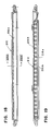
- each vane 18 may be of solid cross section with an aerodynamic teardrop configuration as depicted in Fig. 10.
- each vane 118 may be of a skeletal configuration hollow to the rear as in Fig. 12.
- Each vane is shown mounted on a vertical pivot axis having upper and lower axles 18a axially aligned with upper and lower portions of the frame.
- the vanes when rotated on their axles to a closed position, overlap each other to close off air flow into the engine compartment.
- These axles are preferably stub axles which are integrally formed with the moulded vanes.
- Each vane has a smooth, streamlined convex curvilinear front surface.
- Each has its pivot axis laterally offset from the vane centre so that air pressure during vehicle movement will help hold the closed vanes tightly together without flutter.
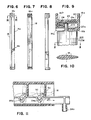
- Bottom frame portion 16b has a plurality of generally cylindrical, equally spaced sockets 16e, which extend vertically down through the bottom portion panel (Fig. 7). These receive the lower cylindrical stub axles of the vanes.
- the through sockets 16e allow any dirt to fall through.
- Aligned with these spaced sockets is a like plurality of axle-receiving sockets 16f in the top portion.
- the sockets in the top portion are horizontal dead-end slots which are open on one end of the slot to allow the upper stub axles on the vanes to be laterally slid into place after the lower axles are inserted into the bottom sockets.
- These upper stub axles are then retained in the inserted position by an elongated, resilient, polymeric snap insert locking bar 20 (Fig. 9).
- Insert 20 has a U-shaped cross sectional configuration. It is shown in Figs. 7 and 9 to fit into an elongated, rearwardly open cavity 22 between upper wall 16b and spaced lower wall 16g (Fig. 9), being slid forwardly into place.
- Insert 20 includes a downwardly extending barb or bayonet type protrusion 20a to snap into an orifice 16h in the lower wall 16g of the upper frame portion 16a.
- the lower leg of resilient U-shaped insert 20 has spaced, open ended slots 20b (Fig. 9) to allow it to be slid over the respective upper axles of the vanes. These slots are spaced equal to the spacing of sockets 16f.
- This insert retainer also secures vane actuator slide bar 24 in place (Fig. 9).
- Slide bar 24 is laterally elongated transversely of the pivotal axes of the vanes and is movable along its length to shift the vanes from closed to open position and vice versa. More specifically, this actuator slide bar 24, a polymeric member having a generally I-shaped cross sectional configuration, has a plurality of spaced, generally U-shaped recesses 24a (Fig. 11). Each recess has a semicircular concavity and a pair of convex curvilinear outer edges. Each recess receives one end lobe of a figure 8 crank 30. Each crank has the other lobe affixed to the upper axles of the vanes.
- Movement of actuator bar 24 in its longitudinal direction causes the interengaged lobes of figure 8 or dumbbell cranks 30 to be pivoted around the axis of the vane axles, and thereby cause the vanes to pivot between the fully open and fully closed position.
- the two positions of the vanes and cranks are shown in dotted lines in Fig. 11.
- a stop element 32 integrally formed on upper frame 14a extends adjacent each of the figure 8 cranks, so that the dumbbell cranks abut the outer ends of the stop elements (see phantom line in Fig. 11), when the vanes reach the fully open position, to arrest the vanes against any further rotation past centre.
- the shutter assembly is shown in the vertical arrangement. However, the features of the illustrated top and bottom frame portions can alternatively be incorporated into the opposite side portions, to cause the vanes to be pivotal on parallel horizontal axes.
- the actuator slide bar 24 may be shifted by a suitable crank 36 (Fig. 1) having one end pivotally engaged with a transversely extending pin 24b (Fig. 11) at the end of the slide bar.
- This pivotal crank is actuated by any suitable electrothermic, pneumatic, hydraulic, electromagnetic or mechanical actuator to rotate about its pivot 36a and thereby shift the slide bar back and forth for rotating the vanes between fully open and fully closed positions.
- each vane can be of the skeletal open back configuration in Fig. 12.
- the forward face of the vane is still convex curvilinear in configuration for lessening of aerodynamic drag.
- This vane has two end panels 120 for mounting two integral axles 118a.
- the rear of the vane is open, i.e., hollow, there being a central reinforcing rib 122 along the length of the vane.
- Each vane in this depicted embodiment has an elongated protruding offset leading edge 124 and a cooperative elongated protruding offset trailing edge 126.
- the leading edge of one vane overlaps and interfits with the trailing edge of the adjacent vane when the vanes are closed, as depicted in Fig. 12.
- the overlapped edges create noise traps to minimize noise transmission from the engine compartment forwardly through the radiator.
- the vanes are actuated with the figure 8 cranks and actuator slide bar previously described.
- Fig. 13 and 14 is depicted an alternative embodiment wherein one end of vanes 18 has a helical spring 33 interconnected between the vane and the adjacent frame. That is, one end of helical spring 33 is mounted in a slot 18′ in the vane axle 18a while the other end is attached to a reciprocable sliding element 16b′ of fixed frame portion 16b.
- An elongated slot 16b ⁇ allows movement of element 16b′ relative to the vane axle 18a. Shifting of sliding element 16b′ in one direction applies a clockwise bias on helical spring 33 to bias the vane to one position, e.g., closed, while shifting element 16b′ in the opposite direction applies a counterclockwise bias on spring 33 to bias the vane to the other position, e.g., open.
- the assembly employs the peripheral frame 212 having parallel upright sides 214a and 214b, a top 216a and a bottom 216b parallel to each other.
- These vanes each have a smooth curvilinear convex streamlined front surface and a hollow ribbed rearwardly open rear surface, as well as a pair of end panels 220 from which axles 218a and 218b extend and with which they are integrally formed.
- the entire vane, reinforcing ribs and axles as well as the offset camming figure 8, i.e., dumbbell, double lobe crank 230 are integrally formed of a polymeric material as by injection moulding.
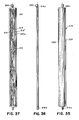
- the particular vane 218 has on its back side, elongated axial, i.e., vertical, ribs 218′ along the central axis. At least one of the opposite edges has horizontal transverse reinforcing ribs 219.
- the vane also has diagonal crisscross ribs 21 (Fig. 37). These ribs provide structural support against deflection under wind pressure, inhibit fluttering, resist torsional distortion and support the vanes against warpage. Yet the structure is lightweight and readily formed as by moulding techniques.
- Each vane has a leading edge 224 and a trailing edge 226.
- the central axis is closer to the trailing edge than to the leading edge to be thereby offset from the physical centre of the vane, thus causing air flow pressure on the leading edge portion of the vane to help retain the vane in a closed position without fluttering.
- the back side of the leading edge 224 has a notch, while the front side of the trailing edge 226 has a notch.
- This frame subassembly is specially formed as by moulding from a polymeric material, to receive the two opposite vane axles in respective pivot sockets. More specifically, the lower pivot pin or axle of each vane is inserted into a respective bottom socket 216e of bottom member 216b, while the upper axle is laterally inserted into a pivot socket which includes a dead end slot 216f (Fig. 15) in a top element 216a of the frame, in cooperation with semicylindrical recesses 223a (Fig. 41) in locking bar 223.
- This locking bar is U-shaped in cross sectional configuration, fitting within an elongated cavity 222 between flanges on the upper element of the frame.
- This locking bar also retains in position a slide bar actuator 225.
- the locking bar is secured in position by having a bayonet type fastener (Fig. 42) at the two inner ends of the two legs of the U-shaped member. Specifically each of the individual segments 221 (Fig. 41) thereof has an outer tapered ramp surface forming part of a hook.
- the locking bar is formed of a resilient polymeric material such that the two legs can be resiliently deformed toward each other during insertion, with the inherent memory thereof causing the hooks to spring back and engage in cooperative recesses in the flanges of the frame for retaining the locking bar and thus the other components noted.
- the upper frame element also preferably includes a plurality of protruding stop pins 216h (Figs. 33 and 34) projecting between the vanes to form a stop surface when engaged by the vanes in the fully open position, and thereby prevent the vanes from moving past centre.
- Slide bar actuator 225 (Figs. 45-47) is an elongated polymeric unit within the outline of the assembly. This ribbed unit is here shown extending across the top of the assembly. (Although this version has the actuator engaging the ends of the vanes, it can actually be mounted to engage the vanes somewhere between the ends, e.g., at the centre, as will be described with respect to Figs. 49-51).
- Figs. 45-47 it includes semicylindrical recesses 225a having concave inner ends and convex edges to receive and cooperate with crank lobes on the vane axles. Transverse end wise movement of slide bar 225 in one direction or the opposite direction will rotate the vanes about their respective pivot axes to open and close the vanes.
- Bar 225 includes a transverse pin 225b at one end engageable by a suitable power actuator mechanism.
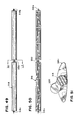
- the vane 318 depicted in Figs. 49-51 is one of several like vanes actuable at the centre thereof, i.e., between its ends, rather than at one end as in the previous embodiments.
- the vane includes end stub axles 318a and 318b. It has a smooth curvilinear front and a hollow ribbed rear. The trailing edge is further from the pivot axis than the leading edge, and is mounted to overlap the leading edge of the adjacent vane when mounted, but is not offset.
- the dumbbell lobe crank 330 extends transversely from the central axles 318c of the vane, for engagement with a centrally positioned actuator bar (not shown) like the actuator bar previously described as located at one end of the vanes.
- a power actuator mechanism for operating a centrally positioned actuator comprises an electrothermal actuator 250 fixedly mounted and having its outer piston rod 252 pivotally engaged with a crank actuator 254 mounted on a pivot pin 256 and having a slot 254′ to receive transverse pin 224b for shifting thereof back and forth. This shiftably operates the actuator slide bar and thus pivots the vanes between open and closed positions.
- Figs. 52-54 is depicted an alternative elongated locking or retention bar 420 to that previously shown and described.
- This bar is also U-shaped with a pair of parallel legs transverse to the connecting leg. both parallel legs are shown to include transverse slots 420b to fit around the stub axles of the vanes when assembly is made.
- This bar is intended to straddle the two flanges on the frame, however, instead of being inserted between them.
- the hook elements (not shown) are on the frame flanges rather than on the locking bar, and the hook-receiving openings 420a are on the locking bar rather than the flanges.
- the member is of resilient material, preferably polymeric, to enable the legs to be temporarily deformable for snapping engagement with the frame, to lock the actuator bar and vanes into position.
- This variation is preferably used with the centre actuated vanes in Figs. 49-51.
Landscapes
- Engineering & Computer Science (AREA)
- Chemical & Material Sciences (AREA)
- Combustion & Propulsion (AREA)
- Mechanical Engineering (AREA)
- Transportation (AREA)
- General Engineering & Computer Science (AREA)
- Cooling, Air Intake And Gas Exhaust, And Fuel Tank Arrangements In Propulsion Units (AREA)
Applications Claiming Priority (1)
| Application Number | Priority Date | Filing Date | Title |
|---|---|---|---|
| US06/921,477 US4753288A (en) | 1986-10-22 | 1986-10-22 | Polymeric shutter assembly |
Publications (1)
| Publication Number | Publication Date |
|---|---|
| EP0327740A1 true EP0327740A1 (de) | 1989-08-16 |
Family
ID=25445488
Family Applications (1)
| Application Number | Title | Priority Date | Filing Date |
|---|---|---|---|
| EP88301028A Withdrawn EP0327740A1 (de) | 1986-10-22 | 1988-02-08 | Kühlerjalousie-Einrichtung |
Country Status (3)
| Country | Link |
|---|---|
| US (1) | US4753288A (de) |
| EP (1) | EP0327740A1 (de) |
| CA (1) | CA1291682C (de) |
Cited By (7)
| Publication number | Priority date | Publication date | Assignee | Title |
|---|---|---|---|---|
| FR2671865A1 (fr) * | 1991-02-21 | 1992-07-24 | Valeo Thermique Moteur Sa | Dispositif a volets pivotants pour la regulation du debit d'air traversant un echangeur de chaleur. |
| DE19715352A1 (de) * | 1997-04-12 | 1998-10-15 | Behr Gmbh & Co | Jalousie, insbesondere für einen Kühlmittelkühler eines Kraftfahrzeuges |
| DE19937153A1 (de) * | 1999-08-06 | 2001-03-01 | Daimler Chrysler Ag | Kühlerjalousie |
| DE19860336C2 (de) * | 1997-12-24 | 2003-02-06 | Ecia Equip Composants Ind Auto | Vorrichtung zur Steuerung eines Luftstromes insbesondere in einem Kraftfahrzeugkühler |
| WO2006034841A1 (de) * | 2004-09-29 | 2006-04-06 | Decoma (Germany) Gmbh | Verschliessbare kraftfahrzeug-kühlergrillanordnung |
| US10471822B2 (en) | 2015-07-31 | 2019-11-12 | Weidplas Gmbh | Ventilation flap assembly for a vehicle |
| CN112693301A (zh) * | 2021-01-12 | 2021-04-23 | 浙江吉利控股集团有限公司 | 一种主动式进气格栅 |
Families Citing this family (62)
| Publication number | Priority date | Publication date | Assignee | Title |
|---|---|---|---|---|
| US4753288A (en) * | 1986-10-22 | 1988-06-28 | Kysor Industrial Corporation | Polymeric shutter assembly |
| US4844092A (en) * | 1988-03-28 | 1989-07-04 | Schneider-Shiley (Usa) Inc. | Catheter Y-connector with guidewire locking means |
| FR2634516B1 (fr) * | 1988-07-20 | 1990-09-14 | Valeo | Dispositif de regulation du debit d'air traversant un radiateur de refroidissement |
| CA1262252A (en) * | 1988-11-02 | 1989-10-10 | Edward J. Gross | Winter front for the grill of a motor vehicle |
| USRE34907E (en) * | 1988-11-14 | 1995-04-18 | Lund Industries Incorporated | Air flow engagement panel element for the grill of a motor vehicle |
| FR2762078B1 (fr) * | 1997-04-09 | 1999-06-18 | Valeo Thermique Moteur Sa | Dispositif a volets pivotants pour le reglage d'un flux d'air, en particulier pour un echangeur de chaleur de vehicule automobile |
| US6179077B1 (en) * | 1997-12-19 | 2001-01-30 | Georgia Tech Research Corporation | Vehicle heat exchanger system and method for a vehicle that augments and modifies aerodynamic forces |
| FR2772676B1 (fr) * | 1997-12-24 | 2000-03-10 | Ecia Equip Composants Ind Auto | Dispositif de pilotage d'un flux d'air et agencement de ce dispositif dans un bloc avant de vehicule automobile |
| US6532909B2 (en) | 2001-03-20 | 2003-03-18 | Siemens Automotive Inc. | Low ram air resistance cooling module with automatic flapper door actuation |
| AT5483U1 (de) | 2001-07-02 | 2002-07-25 | Avl List Gmbh | Jalousie zum verschliessen von öffnungen |
| US20030047365A1 (en) * | 2001-08-08 | 2003-03-13 | Jain Sunil K. | Fluid inlet grille with novel aerodynamic grill bars |
| US6918456B2 (en) * | 2001-08-08 | 2005-07-19 | International Truck International Property Company, Llc | Fluid inlet grille with aerodynamic grille bars |
| JP4667141B2 (ja) * | 2005-07-05 | 2011-04-06 | ヤンマー株式会社 | 旋回作業車 |
| US7559391B2 (en) * | 2006-02-28 | 2009-07-14 | International Truck Intellectual Property Company, Llc | Engine compartment temperature sensitive louvers |
| DE102006016880A1 (de) * | 2006-04-04 | 2007-10-11 | Decoma (Germany) Gmbh | Einrichtung, die dazu ausgebildet ist, als Zusatzteil hinter einem Kühlergitter in einem Motorraum eines Kraftfahrzeugs angeordnet zu werden |
| SE530034C2 (sv) * | 2006-06-30 | 2008-02-12 | Scania Cv Abp | Kylanordning för ett motorfordon |
| SE530032C2 (sv) * | 2006-06-30 | 2008-02-12 | Scania Cv Abp | Kylaranordning för ett motorfordon |
| SE530115C2 (sv) * | 2006-07-03 | 2008-03-04 | Scania Cv Abp | Kylarjalusi |
| US20080043484A1 (en) * | 2006-08-15 | 2008-02-21 | Keng Lien Industrial Co., Ltd. | Automobile radiator housing |
| DE102007025506A1 (de) * | 2007-06-01 | 2008-12-04 | Aurora Konrad G. Schulz Gmbh & Co. Kg | Lamellenwalze |
| DE102008064513A1 (de) * | 2008-12-22 | 2010-06-24 | Veritas Ag | Verstellbare Kühlergrillanordnung |
| JP5424022B2 (ja) * | 2009-03-25 | 2014-02-26 | アイシン精機株式会社 | 可動フィンの駆動装置 |
| US8256387B2 (en) * | 2009-04-28 | 2012-09-04 | Denso International America, Inc. | Radiator shutter using film door technology |
| CA2974627C (en) * | 2009-07-21 | 2018-12-04 | Magna International Inc. | Vehicle compartment louver carrier with integrated ducting |
| US8550887B2 (en) * | 2009-09-18 | 2013-10-08 | Lacks Enterprises, Inc. | Vehicle grill with moveable louvers |
| JP4927973B2 (ja) * | 2009-12-18 | 2012-05-09 | 本田技研工業株式会社 | 車体前部通風構造 |
| JP5573268B2 (ja) * | 2010-03-19 | 2014-08-20 | アイシン精機株式会社 | 車両用可動グリルシャッター |
| DE202010013597U1 (de) * | 2010-09-24 | 2010-11-25 | GM Global Technology Operations, Inc., Detroit | Gehäuse für die Kühlerjalousie eines Kraftfahrzeuges |
| WO2012047528A2 (en) * | 2010-09-27 | 2012-04-12 | Srg Global, Inc. | Shutter system for vehicle grille |
| US8561738B2 (en) * | 2010-11-30 | 2013-10-22 | GM Global Technology Operations LLC | Compound shutter system with independent and non-sequential operation |
| US8544581B2 (en) | 2011-04-04 | 2013-10-01 | Srg Global, Inc. | Drive system for multiple movable systems |
| US20120270490A1 (en) * | 2011-04-21 | 2012-10-25 | GM Global Technology Operations LLC | System and method of shutter control |
| US8807166B2 (en) * | 2011-06-03 | 2014-08-19 | GM Global Technology Operations LLC | Active aero shutters |
| DE102011078461A1 (de) * | 2011-06-30 | 2013-01-03 | Röchling Automotive AG & Co. KG | Schadenssichere Luftklappenanordnung |
| JP5807486B2 (ja) * | 2011-09-28 | 2015-11-10 | アイシン精機株式会社 | グリルシャッタ装置 |
| JP5843609B2 (ja) * | 2011-12-28 | 2016-01-13 | 株式会社ミクニ | シャッター装置 |
| US20130223980A1 (en) * | 2012-02-24 | 2013-08-29 | Shape Corp. | Active grill shutter vane design and vehicle system |
| CH706456B1 (de) * | 2012-04-30 | 2016-03-15 | Schwanden Kunststoff | Jalousie für die Anordnung vor einem Kühler. |
| DE102012011593B4 (de) | 2012-06-13 | 2017-10-19 | Magna Exteriors (Germany) Gmbh | Lastbegrenzer |
| DE102012011595B4 (de) * | 2012-06-13 | 2016-09-15 | Decoma (Germany) Gmbh | Übertragungselement für einen steuerbaren Lufteinlass eines Kraftfahrzeugs |
| WO2013189506A1 (en) * | 2012-06-19 | 2013-12-27 | Volvo Lastvagnar Ab | A device for controlling a gas flow, an exhaust aftertreatment system and a system for propelling a vehicle |
| FR2992590B1 (fr) * | 2012-06-27 | 2015-07-24 | Valeo Systemes Thermiques | Dispositif d'obturation d'entree d'air de face avant de vehicule automobile |
| US9931926B2 (en) | 2012-08-31 | 2018-04-03 | Magna Exteriors Inc. | Active grille multi part modular frame |
| US9694669B2 (en) | 2012-08-31 | 2017-07-04 | Magna International Inc. | Active grille multi part modular frame |
| EP2890580B1 (de) * | 2012-08-31 | 2016-11-02 | Magna International Inc. | Mehrteiliger modularer rahmen für eine aktive grillblende |
| US10029558B2 (en) | 2013-03-15 | 2018-07-24 | Srg Global, Inc. | Grille shutter assembly |
| DE102013107974A1 (de) | 2013-07-25 | 2015-02-19 | Dr. Ing. H.C. F. Porsche Aktiengesellschaft | Luftzufuhreinstellvorrichtung |
| KR101542962B1 (ko) * | 2013-09-09 | 2015-08-10 | 현대자동차 주식회사 | 차량용 액티브 에어 플랩 |
| DE102013110204A1 (de) * | 2013-09-17 | 2015-03-19 | Dr. Ing. H.C. F. Porsche Aktiengesellschaft | Verfahren und Vorrichtung zur Entwärmung eines Wärmetauschers in einem Fahrzeug |
| CA2943374C (en) * | 2014-03-20 | 2019-10-22 | Magna International Inc. | Hollow vane with structure |
| GB2531544A (en) * | 2014-10-21 | 2016-04-27 | Daimler Ag | Grille for a vehicle, in particular a commercial vehicle as well as a vehicle |
| JP6566817B2 (ja) * | 2015-09-29 | 2019-08-28 | 株式会社クボタ | 作業車 |
| FR3046757B1 (fr) * | 2016-01-20 | 2018-01-26 | Valeo Systemes Thermiques | Systeme de gestion d'entree d'air pour obturateur actif de calandre |
| FR3047204B1 (fr) * | 2016-02-03 | 2019-06-14 | Valeo Systemes Thermiques | Systeme de gestion d'entree d'air pour face avant de vehicule automobile |
| FR3061877A1 (fr) * | 2017-01-18 | 2018-07-20 | Valeo Systemes Thermiques | Dispositif d’obturation d’entree d’air de face avant de vehicule automobile et procede de fabrication |
| EP3364121A1 (de) * | 2017-02-16 | 2018-08-22 | HS Marston Aerospace Limited | Strömungsführung für wärmetauscher |
| CN108248538A (zh) * | 2018-01-26 | 2018-07-06 | 芜湖金光汽车配件有限责任公司 | 一种汽车外饰件 |
| FR3080066B1 (fr) * | 2018-04-13 | 2022-08-05 | Valeo Systemes Thermiques | Module d'entree d'air notamment pour vehicule automobile |
| US20210108645A1 (en) * | 2019-10-10 | 2021-04-15 | International Engine Intellectual Property Company, Llc | Vehicle air flow control system |
| CN114056080A (zh) * | 2020-08-07 | 2022-02-18 | 广州法雷奥发动机冷却有限公司 | 一种主动进气格栅组件和车辆前端模块 |
| DE102020131530B3 (de) * | 2020-11-27 | 2021-10-14 | Montaplast Gesellschaft mit beschränkter Haftung | Luftführungssteuerung |
| DE102022114062A1 (de) | 2022-06-03 | 2023-12-14 | Dr. Ing. H.C. F. Porsche Aktiengesellschaft | Luftleitvorrichtung einer Kraftfahrzeugkarosserie eines Kraftfahrzeugs |
Citations (12)
| Publication number | Priority date | Publication date | Assignee | Title |
|---|---|---|---|---|
| GB236309A (en) * | 1924-08-20 | 1925-07-16 | Aubrey Fitzmaurice Inglefield | Improvements in or relating to louvre or shutter devices for controlling the flow ofair to motor car and like radiators |
| US1576507A (en) * | 1922-01-13 | 1926-03-16 | Eliasek Lad | Radiator cover |
| US2200733A (en) * | 1937-01-15 | 1940-05-14 | Pines Winterfront Co | Radiator shutter unit |
| US2248094A (en) * | 1937-02-08 | 1941-07-08 | Walter A Kysor | Shutter mechanism and thermostatic control therefor |
| US2805027A (en) * | 1956-02-23 | 1957-09-03 | Kysor Heater Company | Automatic radiator shutter control |
| US3198298A (en) * | 1961-09-13 | 1965-08-03 | Kysor Heater Co | Shutter slat and slat mounting |
| GB1153361A (en) * | 1966-02-07 | 1969-05-29 | H B R Metal Ind Ltd | Improvements in the Support of Rotatable Devices. |
| US3759056A (en) * | 1972-07-03 | 1973-09-18 | Kysor Industrial Corp | Shutter control system |
| US3759054A (en) * | 1972-07-03 | 1973-09-18 | Kysor Industrial Corp | Split shutter control system |
| FR2404557A1 (fr) * | 1977-09-28 | 1979-04-27 | Peugeot Aciers Et Outillage | Calandre perfectionnee |
| FR2541200A1 (fr) * | 1983-02-18 | 1984-08-24 | Valeo | Dispositif pour l'obturation d'un orifice de passage d'air, en particulier d'air de balayage d'un radiateur dans un circuit de refroidissement de moteur |
| US4753288A (en) * | 1986-10-22 | 1988-06-28 | Kysor Industrial Corporation | Polymeric shutter assembly |
Family Cites Families (1)
| Publication number | Priority date | Publication date | Assignee | Title |
|---|---|---|---|---|
| US1393917A (en) * | 1917-10-01 | 1921-10-18 | Cadillac Motor Car Company | Air-flow-controlling mechanism for internal-combustion-engine radiators |
-
1986
- 1986-10-22 US US06/921,477 patent/US4753288A/en not_active Expired - Fee Related
-
1987
- 1987-10-21 CA CA000549842A patent/CA1291682C/en not_active Expired - Lifetime
-
1988
- 1988-02-08 EP EP88301028A patent/EP0327740A1/de not_active Withdrawn
Patent Citations (12)
| Publication number | Priority date | Publication date | Assignee | Title |
|---|---|---|---|---|
| US1576507A (en) * | 1922-01-13 | 1926-03-16 | Eliasek Lad | Radiator cover |
| GB236309A (en) * | 1924-08-20 | 1925-07-16 | Aubrey Fitzmaurice Inglefield | Improvements in or relating to louvre or shutter devices for controlling the flow ofair to motor car and like radiators |
| US2200733A (en) * | 1937-01-15 | 1940-05-14 | Pines Winterfront Co | Radiator shutter unit |
| US2248094A (en) * | 1937-02-08 | 1941-07-08 | Walter A Kysor | Shutter mechanism and thermostatic control therefor |
| US2805027A (en) * | 1956-02-23 | 1957-09-03 | Kysor Heater Company | Automatic radiator shutter control |
| US3198298A (en) * | 1961-09-13 | 1965-08-03 | Kysor Heater Co | Shutter slat and slat mounting |
| GB1153361A (en) * | 1966-02-07 | 1969-05-29 | H B R Metal Ind Ltd | Improvements in the Support of Rotatable Devices. |
| US3759056A (en) * | 1972-07-03 | 1973-09-18 | Kysor Industrial Corp | Shutter control system |
| US3759054A (en) * | 1972-07-03 | 1973-09-18 | Kysor Industrial Corp | Split shutter control system |
| FR2404557A1 (fr) * | 1977-09-28 | 1979-04-27 | Peugeot Aciers Et Outillage | Calandre perfectionnee |
| FR2541200A1 (fr) * | 1983-02-18 | 1984-08-24 | Valeo | Dispositif pour l'obturation d'un orifice de passage d'air, en particulier d'air de balayage d'un radiateur dans un circuit de refroidissement de moteur |
| US4753288A (en) * | 1986-10-22 | 1988-06-28 | Kysor Industrial Corporation | Polymeric shutter assembly |
Cited By (11)
| Publication number | Priority date | Publication date | Assignee | Title |
|---|---|---|---|---|
| FR2671865A1 (fr) * | 1991-02-21 | 1992-07-24 | Valeo Thermique Moteur Sa | Dispositif a volets pivotants pour la regulation du debit d'air traversant un echangeur de chaleur. |
| EP0500430A1 (de) * | 1991-02-21 | 1992-08-26 | Valeo Thermique Moteur | Drehklappeneinrichtung zur Regelung des Luftstromes durch einen Wärmetauscher |
| DE19715352A1 (de) * | 1997-04-12 | 1998-10-15 | Behr Gmbh & Co | Jalousie, insbesondere für einen Kühlmittelkühler eines Kraftfahrzeuges |
| DE19715352B4 (de) * | 1997-04-12 | 2007-07-19 | Behr Gmbh & Co. Kg | Jalousie, insbesondere für einen Kühlmittelkühler eines Kraftfahrzeuges |
| DE19860336C2 (de) * | 1997-12-24 | 2003-02-06 | Ecia Equip Composants Ind Auto | Vorrichtung zur Steuerung eines Luftstromes insbesondere in einem Kraftfahrzeugkühler |
| DE19937153A1 (de) * | 1999-08-06 | 2001-03-01 | Daimler Chrysler Ag | Kühlerjalousie |
| DE19937153C2 (de) * | 1999-08-06 | 2002-11-14 | Daimler Chrysler Ag | Kühlerjalousie |
| WO2006034841A1 (de) * | 2004-09-29 | 2006-04-06 | Decoma (Germany) Gmbh | Verschliessbare kraftfahrzeug-kühlergrillanordnung |
| US7717208B2 (en) | 2004-09-29 | 2010-05-18 | Decoma (Germany) Gmbh | Closeable motor vehicle radiator grill arrangement |
| US10471822B2 (en) | 2015-07-31 | 2019-11-12 | Weidplas Gmbh | Ventilation flap assembly for a vehicle |
| CN112693301A (zh) * | 2021-01-12 | 2021-04-23 | 浙江吉利控股集团有限公司 | 一种主动式进气格栅 |
Also Published As
| Publication number | Publication date |
|---|---|
| CA1291682C (en) | 1991-11-05 |
| US4753288A (en) | 1988-06-28 |
Similar Documents
| Publication | Publication Date | Title |
|---|---|---|
| EP0327740A1 (de) | Kühlerjalousie-Einrichtung | |
| US6106228A (en) | Fan shroud air door assembly | |
| US10100707B2 (en) | Active grille shutter and shutter subassembly for use with active grill shutters | |
| US9533565B2 (en) | Active grille shutter assembly | |
| EP2716483A1 (de) | Gitterverschluss | |
| CN107303813B (zh) | 用于车辆的前格栅的遮蔽器装置 | |
| US20090295180A1 (en) | Vehicle grab handle | |
| CA2963660C (en) | Active grille shutter multi part modular frame | |
| GB2131150A (en) | Vehicle radiator grille with shuttered operation | |
| US4366685A (en) | Latching assembly for luggage and the like | |
| CA2497102C (en) | Door latch actuator | |
| CN101057052B (zh) | 汽车用门锁装置 | |
| AT4175U1 (de) | Verschliessbarer kühlergrill für kraftfahrzeuge | |
| EP3272565B1 (de) | Kühlerjalousie | |
| JP2004125338A (ja) | 給排気用のグリル | |
| JPH01277616A (ja) | シャッター装置 | |
| CN113043836A (zh) | 一种主动进气格栅组件和车辆前端模块 | |
| CN209870105U (zh) | 一种汽车主动进气格栅 | |
| JP2014069788A (ja) | グリルシャッタ | |
| JP4901016B2 (ja) | インテークマニホールドのバルブ構造 | |
| CN218750291U (zh) | 用于进气格栅的传动装置、相关的进气格栅组件和车辆 | |
| JPH08135506A (ja) | 内燃機関用スロットルボディおよびその製造方法 | |
| KR200180286Y1 (ko) | 원심 개폐식 환풍기 | |
| KR200316141Y1 (ko) | 엔진룸 공기 배출 튜닝장치 | |
| JPS63131945A (ja) | 空気吹出装置 |
Legal Events
| Date | Code | Title | Description |
|---|---|---|---|
| PUAI | Public reference made under article 153(3) epc to a published international application that has entered the european phase |
Free format text: ORIGINAL CODE: 0009012 |
|
| AK | Designated contracting states |
Kind code of ref document: A1 Designated state(s): BE CH DE ES FR GB IT LI NL SE |
|
| 17P | Request for examination filed |
Effective date: 19900213 |
|
| 17Q | First examination report despatched |
Effective date: 19910122 |
|
| STAA | Information on the status of an ep patent application or granted ep patent |
Free format text: STATUS: THE APPLICATION IS DEEMED TO BE WITHDRAWN |
|
| 18D | Application deemed to be withdrawn |
Effective date: 19910604 |