EP0220903B1 - Appareil de traitement d'image - Google Patents
Appareil de traitement d'image Download PDFInfo
- Publication number
- EP0220903B1 EP0220903B1 EP86308109A EP86308109A EP0220903B1 EP 0220903 B1 EP0220903 B1 EP 0220903B1 EP 86308109 A EP86308109 A EP 86308109A EP 86308109 A EP86308109 A EP 86308109A EP 0220903 B1 EP0220903 B1 EP 0220903B1
- Authority
- EP
- European Patent Office
- Prior art keywords
- colour
- signal
- color
- image
- signals
- Prior art date
- Legal status (The legal status is an assumption and is not a legal conclusion. Google has not performed a legal analysis and makes no representation as to the accuracy of the status listed.)
- Expired - Lifetime
Links
- 238000012545 processing Methods 0.000 title claims description 44
- 239000003086 colorant Substances 0.000 claims description 114
- 230000015654 memory Effects 0.000 claims description 102
- 238000000605 extraction Methods 0.000 claims description 53
- 230000003287 optical effect Effects 0.000 claims description 47
- 238000000034 method Methods 0.000 claims description 46
- 238000006243 chemical reaction Methods 0.000 claims description 32
- 238000003860 storage Methods 0.000 claims description 23
- 230000008569 process Effects 0.000 claims description 17
- 238000001514 detection method Methods 0.000 claims description 10
- 230000000295 complement effect Effects 0.000 claims description 5
- 230000004044 response Effects 0.000 claims 6
- 239000000470 constituent Substances 0.000 claims 2
- 239000000872 buffer Substances 0.000 description 97
- 238000010586 diagram Methods 0.000 description 34
- 238000001444 catalytic combustion detection Methods 0.000 description 26
- 239000011159 matrix material Substances 0.000 description 14
- 230000006870 function Effects 0.000 description 12
- 238000012546 transfer Methods 0.000 description 9
- 230000015572 biosynthetic process Effects 0.000 description 8
- 238000001228 spectrum Methods 0.000 description 8
- 238000003672 processing method Methods 0.000 description 6
- 230000035945 sensitivity Effects 0.000 description 6
- 239000000284 extract Substances 0.000 description 5
- 238000000926 separation method Methods 0.000 description 5
- 230000003595 spectral effect Effects 0.000 description 5
- 238000010023 transfer printing Methods 0.000 description 5
- 238000011161 development Methods 0.000 description 4
- 230000003213 activating effect Effects 0.000 description 3
- 238000004519 manufacturing process Methods 0.000 description 3
- 238000012986 modification Methods 0.000 description 3
- 230000004048 modification Effects 0.000 description 3
- 230000007935 neutral effect Effects 0.000 description 3
- 239000013307 optical fiber Substances 0.000 description 3
- 230000003321 amplification Effects 0.000 description 2
- 239000006185 dispersion Substances 0.000 description 2
- 239000000463 material Substances 0.000 description 2
- 239000000203 mixture Substances 0.000 description 2
- 238000012544 monitoring process Methods 0.000 description 2
- 238000003199 nucleic acid amplification method Methods 0.000 description 2
- GGCZERPQGJTIQP-UHFFFAOYSA-N sodium;9,10-dioxoanthracene-2-sulfonic acid Chemical compound [Na+].C1=CC=C2C(=O)C3=CC(S(=O)(=O)O)=CC=C3C(=O)C2=C1 GGCZERPQGJTIQP-UHFFFAOYSA-N 0.000 description 2
- 230000001154 acute effect Effects 0.000 description 1
- 229910021417 amorphous silicon Inorganic materials 0.000 description 1
- 230000005540 biological transmission Effects 0.000 description 1
- 238000004364 calculation method Methods 0.000 description 1
- 239000006229 carbon black Substances 0.000 description 1
- 238000004891 communication Methods 0.000 description 1
- 238000007796 conventional method Methods 0.000 description 1
- 238000013500 data storage Methods 0.000 description 1
- 230000007423 decrease Effects 0.000 description 1
- 239000011521 glass Substances 0.000 description 1
- 238000005286 illumination Methods 0.000 description 1
- 230000006872 improvement Effects 0.000 description 1
- 238000005304 joining Methods 0.000 description 1
- 239000004973 liquid crystal related substance Substances 0.000 description 1
- 238000007639 printing Methods 0.000 description 1
- 230000009467 reduction Effects 0.000 description 1
- 230000001360 synchronised effect Effects 0.000 description 1
- 238000002834 transmittance Methods 0.000 description 1
Images


Classifications
-
- H—ELECTRICITY
- H04—ELECTRIC COMMUNICATION TECHNIQUE
- H04N—PICTORIAL COMMUNICATION, e.g. TELEVISION
- H04N1/00—Scanning, transmission or reproduction of documents or the like, e.g. facsimile transmission; Details thereof
- H04N1/46—Colour picture communication systems
-
- H—ELECTRICITY
- H04—ELECTRIC COMMUNICATION TECHNIQUE
- H04N—PICTORIAL COMMUNICATION, e.g. TELEVISION
- H04N1/00—Scanning, transmission or reproduction of documents or the like, e.g. facsimile transmission; Details thereof
- H04N1/46—Colour picture communication systems
- H04N1/54—Conversion of colour picture signals to a plurality of signals some of which represent particular mixed colours, e.g. for textile printing
Definitions
- the present invention relates to color image processing methods and apparatus that extract colors on color images. More specifically, the present invention relates to color image processing methods and apparatus that can extract achromatic colors in addition to two kinds of colors.
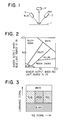
- this mehtod employs a red light source 2 and a blue light source 3 to illuminate a color document 1.
- a photoelectrical conversion means 4 like a CCD receives respective optical information and converts them to electrical signals.
- Output signals from the photoelectrical conversion means 4 are normalized based on the output value of white color paper, and designated as VR and VB, respectively. These two signals are operated to make a color extraction map.
- the 1107 report in the preprints for 1982 conference of Japan Electric & Communication Institute described a color extraction map shown in Fig. 2, and suggested that a plurality of colors may be extracted based on this color extraction map.
- the abscissa axis of Fig. 2 is normalized output (%) from the photoelectrical conversion means 4 when the red light source is on.
- the ordinate axis is normalized output (%) from the photoelectrical conversion means 4 when the blue light source is on.
- This method employs two types of light detection means whose spectral sensitivities are different for one picture element.
- the outputs VA and VB from the light detection means are operated to extract colors.
- This method is disclosed in Japanese Patent Laying-Open Gazette No. 44825/1983.
- the light detection means detects for the vertical luminance signal axis (VA + VB):
- This method employs a plurality of dichroic mirrors, prisms, or R-, G-, B-filters to separate optical information into three colors of red, green, and blue. This method is disclosed in Japanese Patent Laying-Open Gazette No. 62320/1975.
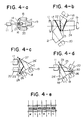
- Fig. 4 illustrates various methods to separate colors.
- the apparatus shown in Fig. 4-a is composed so that colors on an image 12 of a photographic lens 11 are separated into three colors by means of a plurality of relay lenses 13 through 16 and dichroic mirros 17 and 17′, and each color image is formed on a plurality of camera tubes 18 through 20, respectively.
- a plurality of specific shaped prisms 21 through 24 are arranged between the photographic lens 11 and the camera tubes 18 through 20, and the dichroic mirrors 17 and 17′ and inserted respectively between the prisms 21 and 22, and between prisms 23 and 24, so that the colors on the image 12 are separated into three colors.
- Fig. 4-c In the apparatus shown in Fig. 4-c, three prisms 25, 26, and 26′ whose apex angles are an acute angle are engaged and the dichroic mirrors 27 and 28 are inserted between each prism to separate a color image into three colors.
- the prisms shown in Fig. 4-c are inverted. Dichroic mirrors 29 and 30 are formed at boundaries between each prism.
- the above described conventional image processing methods and apparatus can provide means to separate colors, however, the after-steps to process the separated colors are yet under developed.
- Fig. 4-e illustrates an example of color filters arrangement employed in method (b).
- a plurality of color filters are arranged in this order of W (white), Y (yellow), and C (cyan), repeatedly.
- a photoelectric conversion element is equipped on the central portion of each filter as illustrated by diagonal lines in the figure. All light passing through each filter is converted into electrical signals.
- Method (b) requires a plurality of image formation elements, thereby ensuring high speed image formation.
- the image formation system is very expensive and requires a lot of man-hours to be aligned.
- An image formation system that employs a single light detection device and a plurality of color light emitting sources is developed as one attempt to resolve these disadvantages.
- Fig. 4-f illustrates the configuration example of the image formation system.
- 721 is a red/green light source LED; 722, a blue fluorescence panel; 723, an orthochromaic filter; and 724, a cylindrical lens.
- Fig. 4-g shows a spectra example of the light emitting source employed in Fig. 4-f.
- the abscissa axis represents the wave length (nm), and the ordinate axis represents the relative intensity (%).
- R represents the spectrum of the red LED 721; G, the spectrum of the green LED 721; and B, the spectrum of the blue fluorescence panel.
- Fig. 4-h These light sources sequentially emit light with timings shown in Fig. 4-h (a), and illuminates a document 726 placed on a glass plate 725.
- the reflected light from the document 726 enters into a SELFOC lens 727, passes through the lens, and is converted to electrical signals by a CCD adherence sensor 728.
- a transmission pulse is outputted as shown in Fig. 4-h (b).
- Fig. 4-h (c0 electrical charges in the CCD are taken out as a scanning output.
- necessary color signals are obtained by using an apparatus shown in Fig. 4-f, and lighting three color light sources of R, G, and B during scanning line, with arithmetic processing.
- This image forming system provides a small-sized color image processing apparatus with low manufacturing costs.
- the apparatus however, has disadvantages of sophisticated image forming system, and speeding up the image forming is difficult.
- the developed portion is constituted so that the bias voltage can be controlled in a conventional monochrome, analog copying machine. For example, during normal development, the developed bias voltage is lowered to the earth potential for a document of orange or light blue, which has low reflection density, for improving the development ability of such color and effecting sufficient copy density.
- writing utensil manufacturers mix a small quantity of carbon black into the ink.
- black-, blue-, and red-series writing utensils at the same time, some red characters cannot be copied with sufficient density even though black and blue characters are copied with sufficient density. This problem is caused by the different reflection density due to the differences of colors.
- the document FR-A-2444288 discloses apparatus for processing a colour image to provide recording signals for recording a reproduction of said image in a plurality of predetermined colours, said apparatus comprising: optical means for separating an original colour image into a plurality of optical colour components in respect of each pixel in said image; photoelectric conversion means for converting each said optical colour component into an electrical signal; and signal processing means for processing said electrical signals to generate a recording signal for each said pixel.
- the present invention is characterized in that said signal processing means comprises: colour classification means for processing said electrical signals in respect of each said pixel to generate an extracted colour signal representative of a classification of the colour of that pixel into one of said plurality of predetermined recording colours and representative of the density level of the classified colour of that pixel; threshold means for providing a predetermined threshold value density level signal in respect of each said predetermined recording colour; and comparison means for comparing each said extracted colour signal with a threshold value signal from said threshold means to judge whether or not the density level represented by that extracted colour signal is or is not greater than the predetermined threshold value density level represented by the threshold value signal for the predetermined recording colour represented by that same extracted colour signal, and thereby to provide coded output signals constituting said recording signals.
- the present invention thus permits the provision of a threshold value signal representing a different threshold value density level in respect of each colour range in the original colour image to be reproduced, i.e. in respect of each said recording signal, whereby original colour images of different types can each be copied with sufficient density.
- Fig. 5 is a flowchart showing one embodiment of the present invention. Hereinafter, the present invention is described in detail referring to this flowchart.
- the apparatus reads a color document.
- the document should be illuminated with a light source such as one having the spectrum shown in Fig. 6-a.
- a light source such as one having the spectrum shown in Fig. 6-a.
- the abscissa axis represents wave length (nm) and the ordinate axis represents relative intensity (%).
- reflected light from the color document enters into an optical means such as the one shown in Fig. 7, and is separated into Red and Cyan components. That is, the reflected light from the color document enters into a prism 31.
- Fig. 6-b is a graph showing hte characteristics of the dichroic mirror.
- the abscissa axis represents wave length (nm)
- the ordinates axis represents transmittance (%).
- the graph clearly describes the red series light of longer wave length transmitts the dichroic mirror and the cyan series light of shorter wave length is reflected by the dichroic mirror.
- Fig. 6-c is a graph showing the spectral sensitivity of the CCD employed in the present invention.
- the abscissa axis represents were length (nm), and the ordinate axis represents relative sensitivity (%).
- the CCD has a relative sensitivity peak at the wave length of approx. 600 nm.
- These photoelectric conversion signals are normalized by the output value of the reference color (white).
- the nominalized red and cyan light signals are assumed to be as VR and VC, respectively. And these photoelectric conversion signals are again converted into digital data (in this embodiment, 6-bit data) by an A/D conversion unit.
- the apparatus creates a coordinate system according to the digital image data obtained in step 2, and extracts colors based on the created color extraction map. The following are taken into consideration to decide the coordinate system:
- Luminance signal information VR + VC (1) where 0 ⁇ VR ⁇ 1.0 0 ⁇ VC ⁇ 1.0 therefore 0 ⁇ VR + VC ⁇ 2.0
- VR + VC 0 corresponds to the black level
- VR + VC 2.0 corresponds to the white level. Therfore, every color is within the range of 0 to 2.0.
- Color difference signal information VR/(VR + VC), or VC/(VR + VC) (2)
- the value of VR/(VR + VC) or VC/(VR + VC) can be a scale that represents the hue and chroma of a document.
- chromatic colors can be represented as follows:
- Fig. 8-a shows an example of color extraction map representing color gamuts obtained by the above described color extraction method.
- the abscissa axis represents color difference signal VC/(VR + VC); the left ordinate axis, luminance signal VR + VC; and the right ordinate axis, reflection density of achromatic color, respectively.
- the abscissa axis of the example shown in the figure is the color difference signal VC/(VR + VC), however, taking VR/(VR + VC) are the abscissa axis may produce the same results.
- the color extraction map shown in Fig. 8-a is produced and stored within the ROM table.
- Fig. 9 is one example of the ROM table having a capacity of 32 X 32 elements. Therefore, the address bit number consists of 5 bit for row address of (VR + VC) and 5 bit for column address of (VC/(VR + VC)).
- the quantized, density corresponding values (pattern) obtained from the reflection density of the document are stored in this ROM table.
- the coordinate system shown in Fig. 8-a is produced as a form of the ROM table shown in Fig. 9, however, the form is not limited to the ROM table. The means to realize the coordinate system is not restricted to such memory.
- the apparatus converts image data extracted in step 3 into multiple-coded data based on respective threshold value of each color gamut.
- the output device reads the density corresponding values stored in the ROM table using address signals, converts the read data into binary-coded data based on each threshold value assigned to color gamuts of red series, cyan series, and achromatic color, and outputs the binary-coded data.
- the output data are not limited to the binary-coded data, and multiple-coded data may be used.
- a threshold value of "8" is used as the fixed threshold value for red series images in the above described case.
- the threshold value of "8” all red series images of 8 to D are outputted as a binary-code of "1", and expressed with sufficient density.
- Fig. 10 is a block diagram showing configuration of one embodiment of the present invention.
- 41 is a first CCD which receives optical information of red series colors
- 42 a second CCD which receives optical information of cyan series colors
- 51 a first amplifier which amplifies photoelectrical output from the first CCD 41
- 52 a second amplifier which amplifies photoelectrical output from the second CCD 42
- the first and second CCDs 41 and 42 compose a photoelectric conversion means 40
- the first and second amplifiers 51 and 52 compose an amplification unit 50.
- 61 is a first A/D converter which converts the linear output from the first amplifier 51 to digital data
- 62 a second A/D converter which converts the linear output from the second amplifier 52 to digital data.
- the first and second A/D converters 61 and 62 compose an A/D conversion unit 60
- an A/D converter having 6 bit is employed as the A/D converters 61 and 62.
- 72 a first memory which stores the luminance signals (VR + VC); 73, a second memory which stores the color difference signals (VC/(VR + VC)); 81, a third memory which receives, as address signals, the output from the first and second memories 72 and 73, and outputs the data of chromatic colors (red and cyan); 82, a fourth memory which receives, as address signals, the output from the first and second memories 72 and 73, and outputs the data of achromatic colors (black, grey, and white).
- the first and second memories 72 and 73 compose a color extraction information generation means 70.
- the third and fourth memories 81 and 82 compose a color information storage means 80.
- the data in the memories 81 and 82 compose the ROM table shown in Fig. 9.
- 43 is a first buffer which temporarily stores the output from the third memory 81; 44, a second buffer which temporarily stores the output from the fourth memory 82; 45, a color select means which receives color select signals of B (black), B (blue), and R (red) which hereafter is called on B.B.R signal, and the outputs from this means are applied to the first and second buffer 43 and 44; 346, a comparison circuit which compares the image data outputted from either of the first buffer 43 or second buffer 44 with a threshold value, and obtains multiple-coded outputs (including binary-coded outputs); 347, a threshold value circuit which outputs respective threshold value of each color gamut according to the color select signals from the color select means 45.
- a digital comparator is employed as the comparison circuit 346, and a ROM in which respective threshold values corresponding to each color gamut are inputted is used as the threshold value circuit.
- density determination signals are also inputted into the threshold value circuit 347. Therefore, the threshold values are changed by the density determination signals in addition to the color select signals.
- Numerals written in Fig. 10 represent the bit number of the signal lines. Further, the operations of the apparatus configurated above are described as follows.
- the optical information from a color document is injected into the optical means, and separated into red and cyan series as shown in Fig. 7.
- the separated optical information of red and cyan series colors enters into the CCDs 41 and 42, and is converted to electrical signals.
- the converted image singals advance to the amplifiers 51 and 52, and are amplified linearly to a predetermined level, then converted to digital data by the following A/D converters 61 and 62.
- the converted digital data of red and cyan series image data are normalized based on the output value of the reference color (white). That is, assuming the image data of the reference color as "1.0", the image data of red and cyan series are normalized to be VR and VC.
- the luminance signals (VR + VC) are stored into the first memory 72, and the color difference signals (VC/(VR + VC)) are stored into the second memory 73.
- the output signals from the first and second memories 72 and 73 are inputted into the third and fourth memories 81 and 82 as address signals.
- the density corresponding data stored in the addresses inputted into the third and fourth memories 81 and 82 are outputted and held in the buffers 43 and 44.
- the color select means 45 receives B.B.R signals and outputs select signals to either of the first buffer 43 or the second buffer 44. For instance, when the first buffer 43 is selected, density corresponding data of red or cyan are outputted. When the second buffer 44 is selected, density corresponding data of black series (white, grey, and white) are outputted. The outputted density corresponding data enter the comparison circuit 346. Into the threshold value circuit 347 that outputs the threshold values into the comparison circuit 346, color select signals from the color select means 45 and density determination signals are inputted. The threshold value circuit 347 outputs the threshold values corresponding to each color gamut and density value.
- the comparison circuit 46 converts the density corresponding data to binary-coded or multiple-coded data using the threshold values that are set per every color gamut, and density corresponding values.
- a color document data processed by the above mentioned method can be outputted and expressed by inputting these binary-coded data into a printer or copying machine.
- recording means to be represent the binary-coded data such as exposure onto the actionlite surface using optical fiber tube (OFT), liquid crystal display (LCD), or LASER, recording using ink jet, thermal transfer, silver salt, or non-silver salt material, and output onto a CRT.
- the recording means is not limited to the above described examples. Above described steps are repeated whenever the CCDs 41 and 42 receive a new optical information.
- the emtodiment shown in Fig. 10 employs the separately mounted color extraction information generation means 70 and color inormation storage means 80, however, these two means may be integrated into one part.
- the recording means posesses functions to record images with blue, red, and black
- the functions are driven per each color scanning operation during one frame, for example, in the sequence of blue, red, and black, thereby each color is drawn respectively. That is, the following operations are executed; document scanning as first scanning ⁇ density corresponding value output from the ROM table ⁇ blue recording ⁇ document scanning ⁇ density corresponding value output from the ROM table ⁇ red recording ⁇ document scanning ⁇ density corresponding value output from the ROM table ⁇ black recording.
- the output signals from the ROM table to the recording device pass through the gate means (color select means 45, and buffers 43 and 44 shown in Fig. 10) wherein only the output signals assigned in the cyan area are made effective during the blue recording operation.
- the colors of one picture element outputted during three scanning operations are always expressed by red, blue, and black (achromatic color), because VR and VC for one picture element in a color document are one value.
- overlaped color gamuts may be required for each VR or VC. That is, it is required to record one picture element with two or more colors.
- the color gamut is set independent to (VR + VC) and (VC/(VR + VC)), and the separate memories are provided, thereby ensuring to express (reproduce) one picture element with purple or brown.
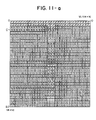
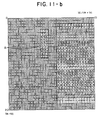
- Fig. 11-a, 11-b and 11-c show examples of the ROM tables according to the present invention, which is an improvement of the color separation map shown in Fig. 9. Each of them has a capacity of 32 x 32 elements capable of being accessed by 5 bit row address (VR + VC) and 5 bit column address (VC/(VR + VC)).
- the quantized, 4 bit density corresponding values (density data) obtained from the reflection density of color documents are stored in these ROM tables.
- the output device reads the density corresponding values using the color select signals, binary-codes the road values using the threshold values assigned to each color gamut, and outputs the binary-coded data.
- the output signals are not limited to binary-coded data, and may be any multiple-coded data.
- Fig. 11-a is a ROM table for black color gamut;
- Fig. 11-b a ROM table for cyan color gamut;
- Fig. 11-c a ROM table for red color gamut.
- the first scanning a document reads the density corresponding values of black from the ROM table shown in Fig. 11-a using B.B.R signals, and permits black toner to adhere to the corresponding positions on the photoconductor drum and transfer them onto a copying paper.
- the second scanning the same document reads the density corresponding values of cyan from the ROM table shown in Fig. 11-b using B.B.R. signlas, and permits blue toner to adhere to the corresponding positions on the photoconductor drum and transfer them onto the same copying paper.
- third scanning the same document reads the density corresponding values of red from the ROM table shown in Fig. 11-c using B.B.R.
- the ROM tables for black color gamut shown in Fig. 11-a
- cyan color gamut shown in Fig. 11-b
- red color gamut shown in Fig. 11-c
- the density corresponding value storage area A, B, C, and D which overlap to the same address area in the other ROM table.
- a certain picture element of a color document (for example, an element on the 5th row and 20th column, hereinafter referred to as (5, 20)) is addressed, and a density corresponding value of zero is outputted from the black memory 83. Therefore, black tonner does not adhere to the copying paper, even after the exposure process based on the binary-coded data, black tonner development, and transfer printing processes.
- the (5, 20) element is again addressed, and a density corresponding value of 7 is outputted from the red memory 81. Red tonner adheres to the copying paper by the binary-coding, exposure based on the binary-coded data, red tonner development, and transfer printing processes.
- the (5, 20) element is further addressed, and a density corresponding value of D is outputted from the cyan memory 82.
- Blue tonner adheres to the portion in the copying paper where red tonner adhered by the same steps of the processes, thereby a purple image is reproduced. That is, the specific density corresponding values are stored within the above described area A, B, C and D. Reading a density corresponding value in the A area of Fig. 11-b and a density corresponding value in the corresponding area of Fig. 11-c using the same address can make a purple image (red + blue). With the same series of processing and concept, reading a density corresponding value in the C area of Fig.
- Fig. 12 shows an embodiment to express neutral colors described above. Comparing to the embodiment shown in Fig. 10, the color information storage means is configurated so that it is separated into each color.
- 81 is a third memory which receives, as addresses, the output from the first and second memories 72 and 73, and outputs density corresponding values of red series colors; 82, a fourth memory which receives, as addresses, the output from the first and second memories 72 and 73, and outputs density corresponding values of cyan series colors; 83, a fifth memory which receives, as addresses, the output from the first and second memories 72 and 73, and outputs density corresponding values of achromatic colors (black, grey, and white).
- the first and second memories 72 and 73 compose the color extraction information generation means 70.
- the third to fifth memories 81 to 83 compose a density information storage means 80.
- an apparatus comprises separated density information storage means per each color gamut.
- the ROM tables shown in Fig. 11-a, 11-b and 11-c are generated and stored in the memories 81 to 83, which receive, as addresses, the output data from the first and second memories 72 and 73, and output, as the image data, the density corresponding values stored in the addressed area.
- 43′ is a third buffer which temporarily stores the output from the third memory 81; 43, a first buffer which temporarily stores the output from the fourth memory 82; 44, a second buffer which temporarily stores the output from the fifth memory 83; 45, is a color select means which receives B.B.R signals, and the output from this means is applied to the first to third buffers 43 to 44.
- the output from either of the first to third buffers 43 to 44 is the output of the apparatus shown in Fig. 12.
- the apparatus may comprise an optical means which obtains optical signals of at least two kinds of colors having a different wavelength from a color document; a photoelectric conversion means which converts the optical signals from the optical means into electrical signals; a color extraction information generation means which arithmetically processes the electrical signals of images outputted from the photoelectrical conversion means, and generates color extraction information based on the operated results; and a density information storage means wherein a plurality of density data storage area that receive, as an address, the output from the color extraction information generation means are equipped separately per each color gamut.
- the color information storage means may be divided into the parts for chromatic and achromatic colors, the outputs from each part may be taken out separately or at the same time depending on the situation, and the information from the color extraction information generation means may be taken out directly as the image data for multiple-coding only during the all black mode as a preferred example of a monochrome mode. That is, the color extraction information generation means, color information storage means, and color control means shown in Fig. 13 are configurated as follows:
- the 72 is a first buffer memory which stores the luminance signal data (VR + VC) of the 5 bits from the right in the 6 bit data; 73, a second buffer memory which stores the color difference data (VC/(VR + VC)); 81, a third memory (red/cyan memory) which receives, as addresses, the output from the first and second memories 72 and 73, and outputs the density corresponding values (density data) of the chromatic colors (red and cyan); 82, a fourth memory (black memory) which receives, as addresses, the output from the first and second memories 72 and 73, and outputs the density corresponding values (density data) of the achromatic colors (black, grey, and white).
- the first and second memories 72 and 73 compose the color extraction information generation means 70.
- the third and fourth memories 81 and 82 compose the color information storage means 80.
- 43 is a first buffer which temporarily stores the output from the third memory 81; 44, a second buffer which temporarily stores the output from the fourth memory 82; 92, a third buffer which directly receives the output from the first memory 72 and temporarily stores the output; 45, a color select means which receives the B.B.R signals and the output from the second memory 73, and the output from this circuit is applied to the first through third buffers 43, 44, and 92.
- the output from either of the first through third buffers 43, 44, and 92 based on the B.B.R signals is the output of the apparatus shown in Fig. 13.
- the first through third buffers 43, 44, and 92, and the color select means 45 compose a color control means 90 which controls the output from the color information storage means 80.
- the color select means 45 drives the third buffer 92 to output the luminance signal data (VR + VC) directly, in this embodiment.
- the embodiment shown in Fig. 13 comprises; an optical means which obtains at least two kins of optical information from a color document; a photoelectrical conversion means which converts optical information from the optical means to electrical signals; a color information means which arithmetically processes the electrical signals from the photoelectrical conversion means, and outputs color extraction information and color information data; and a color control means which controls the output from the color information means.
- This embodiment is characterized in that the output from the color information means is compared with a threshold value, and is directly multiple-coded in a monochromatic mode.
- the luminance signal (VR + VC) is multiple-coded, not the data stored in the memories 81 and 82. Therefore, the image processing is possible using threshold values equivalent to those of a conventional monochromatic digital copying machine, thereby facilitating easy setting of threshold values. Moreover, logical add operations of black data, blue data and red data are not required, thus ensuring simple circuit configuration.
- a color image processing apparatus that is one emtodiment of step 4 described in the flowchart of Fig. 5 is explained referring to Fig. 14, wherein density histogrmas per each color are obtianed by a preliminary scanning; and the number of scanning and threshold values for multiple-coding are decided based on the density histograms; thus ensuring a high speed image formation with a relatively simple configuration.
- Fig. 14 the parts same to those shown in Fig. 10 are designated as the same numbers, 9 is a color document; 5, a read unit which mainly comprises a light source 6; 7, a mirror which introduces an image to an optical means 8; The read unit 5 and the mirror 7 scan the color document in the arrow directions, so called slit-scanning, and introduce the image to a first and a second CCDs 41 and 42.
- 51 is a first amplifier which amplifies the photoelectrically converted output from the first CCD 41; 52, a second amplifier which amplifies the photoelectrically converted output from the second CCD 42;
- the first and second CCDs 41 and 42 compose a photoelectric conversion means 40, and the first and second amplifiers 51 and 52 compose an amplification unit 50.
- 61 is a first A/D converter which converts the output from the first amplifier 51 into digital data; 62; a second A/D converter which converts the output from the second amplifier 52 into digital data;
- the first and second A/D converters compose an A/D conversion unit 60.
- the A/D converters 61 and 62 a 6-bit converter is employed as a preferred example.
- the 72 is a first memory which stores the luminance data (VR + VC); 73, a second memory which stores the color difference signal data (VC/(VR + VC)); 81, a third memory which receives, as addresses, the output from the first and second memories 72 and 73, and outputs the data of chromatic colors (red and cyan); 82, a fourth memory which receives, as addresses, the output from the first and second memories 72 and 73, and outputs the data of achromatic colors (black, grey, and white).
- the first and second memories 72 and 73 compose a color extraction information generation means 70
- the third and fourth memories 81 and 82 compose a color information storage means 80.
- 43 is a first buffer which temporarily stores the output from the third memory 81; 44, a second buffer which temporarily stores the output from the fourth memory 82; 45, a color select means which receives the B.B.R signals and the output from the second memory 73, and the output from this circuit is applied to the first and second buffers 43 and 44; 46, a color judging unit which receives the output from the first and second buffers 43 and 44, counts the data of each color, obtains the density information of each color, and determines the number of scanning operations of the document and threshold value information for multiple-coding operation; (This unit is described in detail later.) 47, a threshold circuit which receives the output from the color judging unit as threshold information, and multiple-codes the output (density data) from the buffers 43 and 44 (including binary-coding); The first and second buffers 43 and 44, color select means 45, and color judging unit 46 compose a color control means 90 which controls the output from the color information storage means 80.
- the output from the threshold circuit 47 is hte
- the optical information advances to the optical means shown in Fig. 7, and is separated into some information according to the wavelength, for instance, into red series and cyan series colors.
- the separated optical information of red and cyan series colors enters into the CCDs 41 and 42, and is converted into electrical signals.
- the converted image signals advance to the amplifiers 51 and 52, and are amplified linearly to a predetermined level, then converted to digital data by the A/D converters 61 and 62.
- the red and cyan image data converted to digital data are normalized with the output value of the reference color (white) is a circuit that is not illustrated in the figure.
- the circuit nromalizes the image data of red and cyan series to let the normalized data be VR and VC.
- a coordinate system is created by the method described in step 3, and colors are extracted based on the color extraction map shown in Fig. 8-a.
- the color document is scanned by a slit exposure optical means that is employed in a usual copying machine, the obtained image passes through the color separation means shown in Fig. 7, and is separated into red and cyan series colors.
- the photoelectric conversion means like CCD receives the separated color signals, converts to the image signals VR and VC, then (VR + VC) and (VC/(VR + VC)).
- the density corresponding values are outputted using these data as addresses according to the color extraction map (table).
- the recording means which records the image onto recording media
- the part is driven per every frame, for example in this order; black, blue, and red, corresponding to each of the scanning operation described above. Thereby each color is printed onto the same medium and overlapped.
- a means which makes only the output assigned in the cyan area to be effective during blue-recording operation, that is, posseses a substantially gate function (color select means 45, buffers 43 and 44 shown in Fig. 2), is equipped in the recording means, thereby a color corresponding to the color gamut in the image processing unit is printed correctly.
- the color extraction map is created and stored in the ROM table, more concretely, in the third and fourth memories 81 and 82.
- red and blue colors can be determined by judging whether or not the color difference signal (VC/(VR + VC)) is larger than 0.5. Therefore, the chromatic color data may be stored in the memory 81 in the group, because the leftmost bit of the color difference signal (VC/(VR + VC)) can determine whether the color is red or blue. To determine whether the cclor is red or blue series, the color difference signal (VC/(VR + VC)) is introduced into the color select means 45.
- the luminance signal (VR + VC) and the color difference signal (VC/(VR + VC)) are stored in the first and second memories 72 and 73, respectively.
- the output from the first and second memories 72 and 73 is given, as address signals, to the third and fourth memories 81 and 82.
- the density data stored in the inputted addresses of the third and fourth memories 81 and 82 are outputted and held in the buffers 43 and 44, respectively wherein the density data is the density corresponding data aforementioned.
- the logical add of the output from the memories 81 and 82 is held in the buffer 92 in this embodiment. (The details are described below.)
- the color judging unit 46 counts the density data of each color from the first and second buffers 43 and 44 during a preliminary scanning operation, obtains density histograms, decides the number of scanning operations based on the density histograms, and sets the threshold values. Moreover, the color judging unit 46 transfers the B.B.R signals to the color select means 45 during the scanning operations, and gives the threshold value data for the multiple-coding (including binary-coding) operation to the threshold value circle 47.
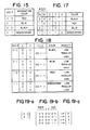
- Fig. 15 is a table showing the relationship betweent he B.B.R signals and the designation color.
- the B.B.R signals are inputted with 2-bit signals.
- the color select means 45 controls the first and second buffers 43 and 44 using the B.B.R signals and the leftmost bit of the color difference signals (VC/(VR + VC)). For instance, when a B.B.R signal of (1 0) shown in Fig. 15 is inputted, the first buffer 43 is made to be effective, and at the same time, an operation is executed using (VC/(VR + VC)) to prevent red and blue confusion, then the buffer 43 outputs red data. This explains a red signal selection operation. However, the same steps are executed during the blue signal selection operation, except a B.B.R signal of (0 1) is inputted.
- the density data of each color are outputted from the apparatus illustrated in the figure. These density data are converted into multiple-coded data (including binary-coded data) using the threshold value that are set per each color gamut by the threshold value circuit 47.
- the color document is reproduced by inputting the multiple-coded data into a printer, copying machine, etc. More concretely, combining the B.B.R signals and designation colors in a developing unit of an output apparatus enables color conversions. When a thermal transfer printing apparatus is employed, color ribbons or color heads are required to be assigned to the B.B.R signals. The above described steps are repeated whenever the CCDs 41 and 42 receive a new optical information.
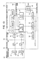
- Fig. 16 is a block diagram showing an embodiment of the color control means 90. The parts same to those shown in Fig. 14 are designated as the same numbers.
- 91 is a first decoder which receives the B.B.R signals for designating color.
- 92 a third buffer (tristate buffer) which receives the logical and signals of the output from the memories 81 and 82.
- the first and second buffers 43 and 44 are tristate buffers.
- THe first output from the decoder 91 enters, as a gate signal E, into the second buffer 44, the logical product of the second and third outputs from the decorder 91 enters into the second decorder 93, and the fourth output enters, as a gate signal G, into the third buffer 92.
- the color difference signal output from the memory 73 and the bit signal (D1) of the B.B.R signals enter into the second decorder 93.
- the logical product signal of the first and fourth outputs from the decorder 93 enters into the first buffer 43 as a gate signal F.
- the logical product signal of athe second and third outputs from the decorder 93 enters into the fourth buffer 94 as a gate signal H.
- the fourth buffer 94 is constituted so that signal 0/1 is inputted by the ON/OFF switching of a switch SW1.
- the output lines from the first to fourth buffers 43, 44, 92, and 94 are commonly connected into a latch means 95.
- 96 is a threshold value ROM in which various threshold data are stored, and the B.B.R signals, density determination signals, and clock CLK are inputted.
- the threshold value ROM 96 is constituted so that optimum threshold data are outputted from this ROM according to the color designation and density data.
- the output from the threshold value ROM 96 is transferred into the latch means 95.
- 97 is a comparison circuit which receives the density data and threshold data per each color, and executes the binary- or multiple-coding process of the image signals. For instance, a digital comparator is employed as the comparison circuit 97. The operation of thus constituted circuit is explained as follows:
- a datum is outputted from the fourth buffer 94 so that no black or white is printed.
- a B.B.R signal is (0 1)
- the operation varies according to whether the leftmost bit of the color difference date (VC/(VR + VC)) is "0" or "1".
- the leftmost bit is "0”
- all of the gate signals E, F, and G from the buffers 43, 44, and 92 turn to "1", causing no density data to be outputted as the same described above.
- the second decorder 93 turns only the gate signal F to "0".
- the B.B.R signal is (1 1), the first decorder 91 turns only the gate signal G to "0". As a result, only the third buffer 92 is activated and outputs logical add data (all black, all red, all blue) of all color data (black data, red data, and blue data), and the outputted data is latched in the latch means 95.
- Fig. 14 an embodiment of monochrome mode is aforementioned wherein both first and second buffers 43 and 44 are made to be effective.
- monochrome mode is also attained by utilizing the third buffer 92 in the above manner.
- the circuit functions so that only designated colors are outputted by outputting white data when a signal of color other than designated is inputted in a usual mode. All black (all red, all blue) signal is outputted when a signal of color other than designated is inputted in a reverse mode. Further, the binary-coding operation using B.B.R is described:
- the B.B.R signals are given to the threshold value ROM 96 as addresses.
- the addresses of the threshold value ROM 96 are decided as given in Fig. 18. Predetermined optimum threshold value may be stored in the corresponding addresses.
- the B.B.R, 2, 3, and CLK in the uppermost line of the table shown in Fig. 18 designate the input terminals of the threshold value ROM 96 in Fig. 16.
- the degree of each color density (low, regular or intermediate, and high) is changed over according to instructions inputted from other unit, for example a control unit (not illustrated in the figure).
- the storing method of the threshold value data into the threshold value ROM 96 is as given in Fig. 19-a, 19-b and 19-c.
- the threshold value data of 2 x 2 matrix shown in Fig. 19-a are stored by each numerical datum shown in Fig. 19-c entered into the addresses corresponding to the data shown in Fig. 19-b.
- the threshold values of 0 ⁇ 2 ⁇ 3 ⁇ 1 are read in this order.
- This step is effective during the multiple-coding (more than three-code) process as well as during the binary-coding process. Changing the relationship between the color designation signal and color producing means enables the color conversion. For example, the blue part in the figure can be replaced with red.
- the threshold values (0, 2, 3, 1) are stored in the matrix as one preferred example, the fixed threshold values, such as (2, 2, 2, 2), can be also applicable as aforementioned.
- Fig. 20 is a block diagram showing an embodiment of the color judging means 46 in Fig. 14. The parts same to those in Fig. 14 and 16 are desiganted the same numbers.
- the density data held in the first through third buffers 43, 44, and 92 are outputted sequentially onto a data bus DB by the select signals from the color select means 45, and enter into the latch means 95.
- an optimum threshold value is inputted from the threshold value circuit 47 according to a color, and the data are converted into multiple-coded (including binarycoded) data in the following threshold value circuit 47 as previously mentioned concerning to the circuit shown in Fig. 16.
- the 100 is a counter which receives a dot clock (clock outputted per each picture element), generates 2-bit, psoudocolor designation signals of B.B.R′, and gives the signals to the color select means 45 through a switch SW11 which is on only during the preliminary scanning operations.
- the B.B.R′ signals are always applied into a decorder 101.
- the monochrome mode is not considered, and the counter 100 is constituted so that the counter does not generate the signal of (1 1) which selects the monochrome data.
- color select signals are sequentially outputted from the color select means 45, and the red-, blue- (cyan), and black-data are taken out, and outputted onto the data bus DB.
- the outputted data of each color are applied to counter 105 through 107 via buffers 102 through 104.
- the decorder 101 sequentially gives a color select signal to the buffers 102 through 104 according to the input signals of (00 ⁇ 01 ⁇ 10).
- the counters 105 through 107 count each input data per each color and create histograms.
- the count values in the counters 105 through 107 are given to the latches 108 through 110 after the preliminary scanning operations.
- the output of the latches 108 through 110 are given to a following judging circuit 111.
- the judging circuit 111 receives the output from the counters 105 through 107 of each color, and decides the scanning number and threshold values for the multiple-coding operations according to each color information and density histograms.
- the number of scanning operations is decided based on the number of colors. For instance, when the number of colors is three of red, blue, and black, the number of scanning operations is three.
- the threshold values for multiple-coding operations are decided as follows:
- the output (density histogram) from each counter has the characteristics shown in Fig. 21-a for a usual color document which comprises a main image and background picture.
- a density point K1 on the concave curve shown in Fig. 21-a is adopted as a threshold value for this kind of characteristics.
- the apparatus control means 112 gives, to the threshold value ROM 96, the addresses to output the optimum threshold value data, and gives, to a B.B.R. signal generating circuit 113, the scanning number information.
- the B.B.R signal generating circuit 113 is equipped with the other means so that the scanning number is also set from the outside.
- the B.B.R signal generating circuit 113 gives B.B.R signals to the threshold value ROM 96 and to the color select means 45 through a switch SW12, as well. During the preliminary scanning operations, the switch SW12 is open. Therefore, B.B.R pseudo-color select signals are given to the color select means 45.
- each threshold value for the colors is decided as TB and TR
- the B.B.R signal that designates red is assigned as (1 0)
- the threshold value of TR is decided during the scanning operation for multiple-coding operation.
- the switch SW11 is off, and the switch SW12 is on.
- the B.B.R signal is assigned as (0 0) that represents black, and the threshold value of TB is decided.
- the scanning operation completes by two scanning in this case.
- the image data read from the color document are multiple-coded and outputted.
- the methods of deciding the threshold values are not restricted to the above described one, and other methods may be applied.
- the multiple-coded data outputted from the threshold value circuit 47 are repreduced by means of output apparatus like a printer.
- this embodiment is characterised in that colors on a color document and density information of each color are obtained by preliminary scanning the color document so that the number of scanning operations and threshold value information for multiple-coding are decided, in a color image processing apparatus which separates colors on the color document, processes and forms color images.
- a color image processing apparatus which is configurated so that an optical means scans a color document and separates the document to a plurality of images, each of which has a specific spectrum characteristics; the separated optical image signals are arithmetically processed to obtain the color extraction information; and the density data per each color that are stored in each information storage means are selected by the color extraction information: as another embodiment of step 4 in the flow chart shown in Fig.
- a means may be configurated so that color information is obtained during a first document scanning operation, and a following scanning operation is controlled based on the color information (including a control to stop the next scanning).
- the first and second buffers 43, and 44, color select means 45, color discrimination circuit 46′, and B.B.R generating circuit 47′ compose the color control means 90 which controls the output from the color information storage means 80.
- the output from either of the first or second buffer 43 or 44 is the output of the apparatus shown in the figure.
- the color discrimination circuit 46′ receives (VR + VC) signals from the first memory 72 and (VC/(VR + VC)) signals from the second memory 73, automatically judges a color contained in a color document (the details are described below), and transfers control signals based on the judging results to the B.B.R generating circuit 47′.
- the B.B.R generating circuit 47′ receives the control signals from the color discrimination circuit 46′, generates B.B.R signals, and transfers them to the color select means 45.
- the color select means 45 receives the B.B.R signals and gives select signals to either of the first or second buffer 43 or 44.
- the relationship betweent he B.B.R signal and color designation is as given in Fig. 15.
- the B.B.R signal is inputted with 2-bit.
- the color select means 45 controls the first and second buffers 43 and 44 using the B.B.R signals and the leftmost bit of the (VC/(VR + VC)) signal. For instance, as given in Fig. 15, inputting a (1 0) makes the first buffer 43 to be effective, and red data is outputted from the buffer 43. At the same time, an operation is executed using the (VC/(VR + VC)) signal to prevent red and blue confusion.
- the above example explains the red signal selection.
- the blue signal selection is the same operation as the above except that a (0 1) signal is inputted.
- the second buffer 44 When a (0 0) is inputted, the second buffer 44 is activated and outputs only the contents in the black memory. Inputting a (1 1) turns the current mode to the monochromatic mode, and both first and second buffers 43 and 44 are activated in this mode (both red and blue colors on the color document are made to black).
- density data per each color may be outputted from the apparatus shown in the figure.
- These density data are converted into binary-coded date (some cases to multiple-coded data) in a binary-coding circuit (that is not shown in the figure) using threshold values set per each color gamut.
- the original image data are outputted and reproduced by inputting the binary-coded date into a printer or copying machine.
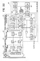
- Fig. 23 is a block diagram showing a concrete configuration of the color control means 90 in this embodiment.
- the configuration is similar to that shown in Fig. 16, however, the CLK signals are inputted, and no B.B.R signal is inputted into the threshold value ROM 96, in which various threshold value date are stored.
- the threshold value ROM 96 is configurated so that it outputs optimum threshold values to the latch 95.
- the configuration and function of the other parts are the same to those shown in Fig. 16. That is; 91 is the first decorder which receives B.B.R signals: 92, the third buffer (tristate buffer) which receives the logical add signal of the outputs from the memories 81 and 82.
- the first and second buffers 43 and 44 are also tristate buffers.
- the first output from the decorder 91 enters, as a gate signal E, to the second buffer 44.
- a logical product signal of the second and third outputs enters into the second decorder 93, the fourth output enters, as a gate signal G, into the third buffer 92.
- the color difference signal, the leftmost bit (D1) of the B.B.R signal enter into the second decorder 93.
- a logical product signal of the first and fourth outputs from the decorder 93 enters, as a gate signal F, into the first buffer 43.
- a logical product signal of the second and third outputs enters, as a gate signal H, into the fourth buffer 94.
- signals 0/1 is inputted by the on/off of a switch SW1.
- the output lines from the first through fourth buffers 43, 44, 92, and 94 are connected in common to the latch 95.
- Fig. 24 is a block diagram showing concrete configuration of the color discrimination circuit 46′.
- 201 through 204 are comparators which receive the (VR + VC) signal in common
- 205 and 206 comparators which receive the (VC/(VR + VC)) signal in common
- These comparators 201 through 206 have each reference datum of A′ to F′ inputted in advance as given in the figure, and compare input data and the reference datum.
- These reference data A′ to F′ correspond to the coordinate values shown in the color extraction map of Fig. 25, wherein the values are set on the color boundary line.
- the color extraction map shown in Fig. 25 corresponds to that in Fig. 8.
- 207 is a gate circuit which receives the outputs from the comparators 201 through 206, and generates various gate signals:
- the gate circuit 207 comprises a plurality of gate combinations, and outputs 9 kinds of gate signals.
- Each final step gate is G1 through G9 as shown in Fig. 24.
- 208 is an OR gate which receives gate signals from G3, G5, G6, and G9; 209, an OR gate which receives gate signals from G1, G4, and G7;
- the OR gate 208 outputs black information data, and the OR gate 209 outputs white information data.
- 210 is a counter which receives the output from the OR gate 208, and counts black information data; 211, a counter which receives the output from the gate G8, and counts blue information data; 212, a counter which receives the output from the gate G2, and counts red information data; 213, a counter which receives the output from the OR gate 209, and counts white information data: 214, a judging circuit which receives outputs from the counters 210 through 213, and outputs control signals for color selection.
- the operation of thus configurated circuit is further explained; It is assumed that a color on a color document at a first scanning is red. As clearly illustrated in the color extraction map of Fig.
- red signal data must satisfy: A′ ⁇ VR + VC ⁇ C′ O ⁇ VC/(VR + VC) ⁇ E′
- the color data of red picture elements are judged the position on the color gamut shown in Fig. 25 during the first scanning operation, and count the number of picture element positioned each color gamut by the counters 210 to 213.
- the judging circuit 214 receives outputs from the counters 210 to 213, judges the number of colors on the document based on the count values, and outputs control signals depending on the judgement. That is, the circuit determines a color to be outputted, decides the color sequence for outputting for the determined color, and controls the scanning operation. The circuit judges whether or not a color exists on the document using the output values from the counters 210, 211, 212, and 213.
- the T value may be changed per each color, however, in an actual circuit, it is preferable to decide considering stain on the image that the value may be set around several tens for example.
- This control signal enters into the B.B.R generating circuit 47 (refer to Fig. 22). As described above, the B.B.R generating circuit 47 receives the control signal, generates B.B.R signals, and gives them to the color select means 45. Thus, the circuit shown in Fig. 22 forms images read by a scanner.
- the color counting operations may be executed for all picture elements on a color document, or for discretely sampled elements.
- the determination operation of the color number by the color descrimination circuit 46′ may be executed by a microcomputer or specially designed hardware.
- the counters 210 to 213 are not required to have the same maximum count values, because the counter for black may require a maximum count vlaue higher than the other colors.
- the maximum count vlaue only requires a level the can eliminate noise thereby reducing the manufacturing cost.
- blue, black and red color are used as the color select signals, however, the present invention is not restricted to them.
- Y.M.C sereis colors may be employed to extract colors on a document.
- the present invention is applicable to an embodiment, wherein effective size of one picture element is charged by changing the speed of SUB SCAN so as to become high speed during the first scanning operation.
- the color image data outputted from the buffer 43 or 44 are binary- or multiple-coded, and then, reproduced as a color image by an output apparatus.
- Fig. 26 is a timing chart showing the operation, wherein the B.B.R signal is black during the first scanning when the color document is consisted of black, grey, white, and colors withint he red area in the color extraction map.
- 26-a represents the reading timing
- 26-b color disccrimination sequence
- 26-c B.B.R signals
- 26-d recording operation.
- a color image processing apparatus which is configurated so that a plurality of optical information, each of which has a specific spectrum characteristics, and each image signal are obtained from a color document; the density data per each color are obtained based on the image signals; and color designation signals make the density data be effective or ineffective; as another embodiment of step 4 in the flowchart shown in Fig.
- a means may be configurated so that the addresses in the memory for threshold value data output are decided using the color designation signals during the multiple-coding operation of the density data.
- the addresses in the memory for threshold value data output are decided using the color designation signals during the multiple-coding operation of the density data.
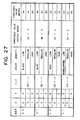
- the binary coding operation using the B.B.R signal for designation color is further explained:
- the B.B.R signals are given to the threshold value ROM 96 as addresses.
- the addresses of the threshold value ROM 96 are decided as given in Fig. 27.
- the predetermined optimum threshould values may be stored in the corresponding addresses.
- the B.B.R, 2, 3, and CLK in the uppermost line of the table shown in Fig. 27 designate the input terminals of the threshold value ROM 96.
- the degree of each color density (low, regular, and high) is changed over according to instructions inputted from other unit, for example a control unit (not illustrated in the figure). As clearly shown in Fig.
- the optimum threshold value matrix group for black color (A0 to A2) is selected. If the color document is wanted to be reproduced with low density, the threshold value matrix A0 is selected.
- the circuit is configurated so that an optimum threshold matrix is selected in the threshold value matrix group B0 to B2 for blue, in the threshold value matrix group C0 to C2 for red color, and in the threshold value matrix D0 to D2 for monochrome.
- the CLK gives a threshold value address in the threshold value matrix, and selects a threshold value (this function is described below).
- the storing method of the threshold value data into the threshold value ROM 96 is as given in Fig. 19.
- the threshold value data of 2 x 2 matrix shown in Fig. 19-a are stored by each numerical datum shown in Fig. 19-c entered into the addresses corresponding to the data shown in Fig. 19-b.
- the threshold values of 0 ⁇ 2 ⁇ 3 ⁇ 1 are read in this order. This step is effective during the multiple-coding (more than three-codes) process as well as during the binary-coding process. Changing the relationship between the color designation signal and color output means enables the color conversion. For example, the blue part in the figure can be replaced with red.
- Fig. 28 is a block diagram showing another embodiment of the present invention, wherein the color extraction information generation means and the color information storage means are integrated. The parts same to those in Fig. 10 are designated the same number.
- the digital image data from the A/D conversion unit 60 enter into the processing circuit 71.
- the processing circuit 71 receives input image data, calcualtes VR and VC, and obtains the luminance signal (VR + VC) and color difference signal (VC/(VR + VC)) These values directly enter into the memories 81 and 82 as address data.
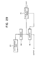
- Fig. 29 is a block diagram showing another embodiment of the present invention, wherein the color extraction means and color information storage means are integrated. The parts same to those in Fig. 10 are desgnated the same numbers.
- the digital image data from the A/D conversion unit 60 enters into the memory 84. Both density corresponding values and color code data are stored in the memory 84.
- the output from the memory 84, i.e. this code, and color select signal select a color, thereby data are outputted or no data are outputted from the buffer 46.
- the following operations are the same to those in Fig. 10, therefore the explanation is omitted.
- the abscissa axis of the color extraction map shown in Fig. 8 is assumed as (VC/(VR + VC)), however, it may be assumed as (VR/(VR + VC)).
- the similar function may be attained by assuming the abscissa axis as (VR - VC)/(VR + VC) or (VC - VR)/(VR + VC).
- the abscissa axis as (VR - VC)/(VR + VC)
- the spectral characteristic of the employed dichroic mirror is that red series colors transmit it and cyan series colors are reflected by it.
- the present invention is not restricted to it. Any dichroic mirros may be employed, which can separate colors into two complementary colors, for example, green and magenta, or blue and yellow.
- the color separation means is not restricted to the dichroic mirrors. Any means which can separate colors, for instance, spectro-filters may be employed.
- the color extraction map is not limited to the T-shaped one shown in Fig. 8. Any type of color extraction map may be used.
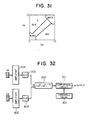
- Fig. 30 extracts colors based on a condition that optical information can be extracted with the color extraction map shown in Fig. 31.
- the red signal VR and blue signal VB converted to electrical signals by photoelectircal conversion means 301 and 301′ are amplified by amplifiers 302 and 302′, converted into digital data by A/D converters 303 and 303′, and given, as addresses, to a red memory 304, a blue memory 305, and a black memory 306, respectively.
- the memories 304 through 306 compose a ROM table based on the color extraction map shown in Fig. 31.
- Image data selected by the B.B.R signals are outputted, enter into the corresponding buffer memories 307 through 309, and are held in them.
- the output data from the buffer selected by a color select means 310 are multiple-coded by a comparison circuit 311.
- the threshold value of the comparison circuit 311 is given by a threshold value circuit 312, to which color select signals are given from the color select means 310.
- the threshold value circuit 312 generates a threshold value depending on each color gamut.
- respective threshold value can be set per one color gamut.
- a plurality of threshold values may be set instead of employing a fixed threshold value per each color gamut. That is, the threshold value circuit may be configurated so that threshold value groups like dither matrix are set.
- the computed Z vlaue may be assumed as luminance signal data as described above. Therefore, the Z values may be compared with a threshold value from a threshold value circuit 322 in a comparison circuit 321, and thus, may be binary-coded.
- a computing element 314, which obtains the Z value by operating root (VR2 + VB2), and a computing element 313, which operates (VR - VB), are equipped.
- the output from the computing elements 313 and 314 is given, as addresses, to the memories 304 through 306, and the output from the computing element 314 is given to the threshold value circuit 312 as addresses for selecting threshold values.
- the computing element 313 is equipped because a color can be determined, for instance, it is red series if VR is larger than VB, and it is blue series when VB is larger than VR. Thereby, after deciding threshold values using density histogram per each color obtained during a preliminary scanning operation, the threshold values may be used for the multiple-coding (including binary-coding) operations during the scanning operations.
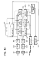
- Fig. 34 is a block diagram showing other embodiment of the present invention.
- Optical information separated into red, green, and blue series colors by an optical system is photoelectrically converted to electrical signals by per each series by CCDs 491 through 493.
- the photoelectrically converted signals are amplified to a predetermined level by the following amplifiers 404 through 496, and converted to digital data in A/D converters 497 through 499.
- the output from the A/D converters 497 through 499 enters into a processing circuit (color extraction information generation circuit) 400, and is processed with a predetermined arithmetic opetation.
- density corresponding values of cyan, density corresponding values of magenta, and density corresponding values of yellow are stored per each color gamut in the memories 401, 402, and 403, respectively.
- the processing circuit 400 receives input data of R. G. and B, and converts them to select density corresponding values of cyan, magenta, and yellow.
- the converted data are ginen to the memories 401 through 403 as address.
- the memories 401 through 403 output density corresponding value stored in the given addresses.
- a color select means 407 receives R.G.B select signals, and select one buffer from the buffers 404 through 406.
- the output from the selected buffer enters into the comparison circuit 408, is compared to the threshold value given from the threshold value circuit 409, and is multiple-coded (including binary-coded).
- the multiple-code output is the output of the apparatus shown in the figure.
- color select signals from the color select means 407 and density determination signals are inputted, thereby the threshold value circuit 409 can output an optimum threshold value.
- a color extraction information generation circuit By integrating a color extraction information generation circuit to the processing circuit 400, and by monitoring whether or not the color extraction information generation circuit 400 indicates a color corresponding to document image to the memories 401 through 403 in which each color data of Y. M. and C are stored during document scanning operation, it can be determined what colors are involved in the document.
- 410 through 412 are counters which count the number of indications of corresponding color to the memories 401 through 403. Color control signals can be obtained from the counted values of these counters. Further, according to this embodiment, a density corresponding values can be obtained in the similar manner to the color extraction map shown in Fig. 2.
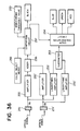
- the embodiment shown in Fig. 35 is configurated so that it outputs density corresponding values per each color gamut as the same to the embodiment shown in Fig. 34.
- the optical information separated into red and blue series are converted into electrical signals in a photoelectrical conversion element 511, and amplified to a predetermined level by a following amplifier 512.
- the amplified image signals enter into an A/D converter 513, and are converted into digital data.
- the output VR and VB from the A/D converter 513 enter into a processing circuit 516 synchronized by a selector 514 and a line memory 515, thereby operated by predetermined arithmetical processing.
- the processing circuit 517 receives the input data of VR and VB, and converts them to select density corresponding values of C, M, and Y.
- the converted data are given to the memories 518 through 520 as addresses.
- the memories 518 through 520 output density corresponding values stored in the corresponding addresses.
- the outputted density corresponding values are held in buffers 521 through 523 temporarily.
- the color select means 524 selects one buffer from the buffers 521 through 523.
- the output from the selected buffer enters into a comparison circuit 525, is compared with the threshold value given from the threshold value circuit 526, and multiple-coded (including binary-coded).
- the multiple-coded output is the output of the apparatus shown in the figure.
- the color select signals from the color select means 524 and density determination signals are inputted into the threshold value circuit 526 as described above, thereby the threshold value circuit 526 outputs optimum threshold values.
- Fig. 36 is a block diagram showning an application of the present invention.
- the apparatus shown in this figure separates colors on a document into three elementary colors of red, green, and blue based on the color extraction map shown in Fig. 3.
- the abscissa axis represents hue signal
- the ordinate axis respresents luminance signal.
- Two kinds of optical signals are converted to electrical signals VA and VB by photoelectrical conversion means 251 and 251′ like CCDs.
- the converted electrical signals are inputted into logarithmic amplifiers 252 and 252′, and logarithmically amplified.
- the logarithmically amplified signals log VA and log VB are subjected to the processing of (log VA - log VB) in the following subtractor 253.
- the following color descrimination circuit 254 determines as follows:
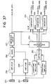
- Fig. 37 is a block diagram showing another embodiment of the present invention.
- the embodiment is configurated by modifying the embodiment shown in Fig. 30 so that density of a color on a document is known by creating the (VA + VB) density histograms of blue, green, and red as the same to the embodiment shown in Fig. 14, thereby the threshold values can be decided per each color gamut. That is, by providing, to the comparison circuit 257, the density histogram and threshold value creating functions, the threshold values created per each color gamut are given, as reference values, from the comparison circuit 257 to each comparator 268 through 270, thereby the image data outputted from the color discrimination circuit 256 are multiple-coded.
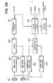
- the embodiment shown in Fig. 38 is also a modification of the embodiment shown in Fig. 36.
- the output from the color discrimination circuit 254 is also inputted into a R.G.B counter 271. If a color document contains a lot of colors, the vlaue of (log VA - log VB) varies within a wide range during a scanning operation. Assuming that the value of (log VA - log VB) is quantized as 5 bit (32 levels), it is known what color is contained in the document by monitoring which bit turns to "1".
- the R.G.B counter 271 monitors the bit signals, determines the kind of colors, and outputs color control signals.
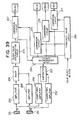
- the embodiment shown in Fig. 39 is also a modification of the embodiment shown in Fig. 36. In this embodiment, the operated output from an adder 256 is determined by a black color dicrimination circuit 272 as follows:
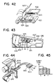
- Figs. 41 through 44 illustrate the configurations of output apparatus.
- Figs. 41, 42, 43, and 44 illustrate a laser printer, thermal transfer printer, optical fiber tube recording apparatus, and bubble jet color printer, respectively. Further, the operation of the laser printer shown in Fig. 41 is explained.
- a laser unit 610 injects modulation light modulated by the density data of red color that the selected by the B.B.R signals.
- the injected modulation light exposes the surface of a photoconductor drum 611.
- red toner is adhered to the exposed photoconductor drum 611 by a developing unit 612, where only a red developer functions, then transferred onto a copying paper fed from a paper feed cassette 613.
- the photoconductor drum 611 rotates one turn, receives initial charging at an initial charging unit 614, then the lasar unit 610 injects modulation light modulated by the blue density data selected by the B.B.R signals.
- the injected modulation light exposes the surface of the photoconductor drum 611.
- blue toner is adhered by the developing unit 612, in which only a blue developer functions at this time.
- the blue toner adhered to the photoconductor drum 611 is transferred onto the same copying paper.
- the photoconductor drum 611 rotates one more turn, receives initial charging at the initial charging unit 614, then the lasar unit 610 injects modulation light modulated by the black density data selected by the B.B.R signals.
- the injected modulation light exposes the surface of the photoconductor drum 611.
- black toner is adhered by the developing unit 612, in which only a black developer functions at this time.
- the black toner adhered to the photodrum 611 is transferred onto the same copying paper.
- the copying paper transfer-printed with predetermined colors is fed to a fixing unit 615 and fixed as a color image.
- the laser unit injects modulation light modulated by the data, for instance, from the third buffer 45 hwich is selected by the B.B.R signals as described in the embodiment shown in Fig. 13.
- the injected modulation light exposes the surface of the photoconductor drum 611.
- black toner is adhered by the developing unit 612, in which only a black developer functions at this time.
- the black toner adhered to the photoconductor drum 611 is transferred onto a copying paper fed from the paper feed cassette 613.
- the copying paper transfer-printed with black toner is fed to the fixing unit 615 and fixed as a color image.
- the oepration of the thermal transfer printer shown in Fig. 42 is described as follows.
- an ink ribbon 621 on which 4 colors of Y (yellow), M (magenta), C (cyan), and B (black) are adhered continuously moves in the arrow direction shown in the figure.
- a copying paper 623 fed from a paper feed cassette 622 is fed to a platen 624.
- Each color toner on the ink ribbon 621, which is melted by a thermal head 625, is transfer-printed onto the copying paper 623.
- the transfer-printed copying paper 623 is fed out.
- Image information displayed on a CRT 631 is converged by a lens 632, reflected by a mirror 633, and enters into an actionolite member 634, and exposes it.
- the exposed actionolite member 634 is fed to a developing unit 635, and developed by each developer of cyan, magenta, and yellow.
- the developed member 634 is also fed to a transfer-printing unit 636.
- a copying paper 637 is fixed in a fixing unit (not shown in the figure), and fed out.
- a bubble jet head 642 is moutned on a head feed table 641.
- each color ink is fed from an ink tank 643 of Y (yellow), M (magenta), C (cyan), and BLK (black).
- Y yellow
- M magenta
- C cyan
- BLK black
Landscapes
- Engineering & Computer Science (AREA)
- Multimedia (AREA)
- Signal Processing (AREA)
- Textile Engineering (AREA)
- Color Image Communication Systems (AREA)
- Facsimile Image Signal Circuits (AREA)
Claims (20)
- Un appareil de traitement d'une image en couleurs pour fournir des signaux d'enregistrement dans le but d'enregistrer une reproduction de ladite image en une pluralité de couleurs prédéterminées, ledit appareil comprenant:
un moyen optique (31,32,33) pour séparer une image en couleurs originale en une pluralité d'éléments optiques de couleur pour chaque pixel de ladite image;
un moyen de conversion photoélectrique (40,50,60) pour convertir chacun desdits éléments optiques de couleur en un signal électrique; et
un moyen de traitement de signaux (70,80,346,347) pour traiter lesdits signaux électriques et générer un signal d'enregistrement pour chacun desdits pixels;
caractérisé en ce que ledit moyen de traitement de signaux comprend:
un moyen de classification de couleurs (70,80) pour traiter lesdits signaux électriques pour chacun desdits pixels de manière à générer un signal de couleur extrait représentatif d'une classification de la couleur de ce pixel en l'une de ladite pluralité de couleurs d'enregistrement prédéterminées et représentatif du niveau de densité de la couleur classifiée de ce pixel;
un moyen de seuil (347) pour fournir un signal de niveau de densité à valeur de seuil prédéterminée pour chacune desdites couleurs d'enregistrement prédéterminées; et
un moyen de comparaison (346) pour comparer ledit signal de couleur extrait à un signal de valeur de seuil provenant dudit moyen de seuil (347) pour juger si oui ou non le niveau de densité représenté par ce signal de couleur extrait est supérieur ou non au niveau de densité de la valeur de seuil prédéterminé représenté par le signal de valeur de seuil pour la couleur d'enregistrement prédéterminée représentée par ce même signal de couleur extrait, et par là même produire des signaux à sortie codée constituant lesdits signaux d'enregistrement. - Un appareil selon la revendication 1 caractérisé par une pluralité de moyens de stockage (43,44) pour stocker respectivement les signaux de couleur extraits fournis par ledit moyen de classification de couleurs (70,80) conformément à la couleur classifiée représentée par ce signal de couleur extrait, et un moyen de sélection (45) actionnable en réponse à un signal de désignation de couleur d'enregistrement (BBR) pour sélectionner l'un desdits moyens de stockage (43,44) pour fournir audit moyen de comparaison (346) le signal de couleur extrait qui y est stocké.
- Un appareil selon la revendication 2 caractérisé en ce que le moyen de sélection (45) est d'autre part actionnable en réponse à un signal désignant un mode d'enregistrement couleur ou un mode d'enregistrement monochrome, et qui, en réponse au signal de mode monochrome, entraîne la fourniture directe (92) audit moyen de comparaison (346) d'un signal représentatif de la luminance de l'image couleur originale et fourni par ledit moyen de traitement de signaux (70).
- Un appareil selon l'une quelconque des revendications 1 à 3 caractérisé en ce que ledit moyen de classification de couleurs (70,80) comporte une mémoire (81,82) pour stocker une matrice de données de couleurs classifiées.
- Un appareil selon la revendication 4 caractérisé en ce que ledit moyen de classification de couleurs (70,80) comporte un moyen d'extraction (72,73) actionnable en réponse audits signaux électriques pour chacun desdits pixels pour en générer un signal d'adresse, et dans lequel ladite mémoire (81,82) est actionnable en réponse audit signal d'adresse pour extraire des données sélectionnées de couleurs classifiées à l'adresse correspondante dans ladite matrice pour servir dudit signal de couleur extrait pour ce pixel.
- Un appareil selon la revendication 5 caractérisé en ce que ledit moyen d'extraction (72,73) est actionnable pour générer un premier et un second signal d'adresse représentant respectivement la luminance et une différence de couleur dans ladite image en couleurs originale.
- Un appareil selon l'une quelconque des revendications 1 à 6 caractérisé en ce que ledit moyen optique (31,32,33) est actionnable pour séparer ladite image en couleurs originale en une paire de composantes couleur complémentaires.
- Un appareil selon la revendication 7 caractérisé en ce que lesdites couleurs complémentaires sont rouge et cyan.
- Un appareil selon l'une quelconque des revendications 1 à 8 caractérisé par un moyen de génération de signal de désignation de couleur d'enregistrement (113) actionnable pour fournir une pluralité de signaux de désignation en séquence, chacun desdits signaux de désignation désignant l'une des dites couleurs d'enregistrement.
- Un appareil selon la revendication 9 caractérisé en ce que ledit moyen optique (31,32,33) comprend un moyen (8) pour explorer ladite image originale, ledit moyen d'exploration étant actionnable pour explorer sur ladite image originale chacune desdites couleurs d'enregistrement en réponse à ladite séquence de signaux de désignation.
- Un appareil selon la revendication 10 caractérisé par un moyen (610) pour reproduire ladite image sur un support d'enregistrement, ledit moyen de reproduction étant actionnable pour reproduire la composante de ladite image qui correspond à ladite couleur désignée pour chaque balayage par ledit moyen d'exploration (8), et qui reproduit une pluralité desdites composantes d'image en succession sur le même support d'enregistrement pour créer l'image en couleurs reproduite.
- Un appareil selon l'une quelconque des revendications 1 à 11 caractérisé par un moyen (46) pour créer un histogramme de densité de ladite image originale en comptant dans un compteur (105-107) les données de densité desdits signaux de couleur extraits, et en ce que ledit moyen de traitement de signaux (70,80,346,347) est actionnable pour déterminer ladite valeur de seuil pour chaque couleur d'enregistrement d'après ledit histogramme de densité.
- Une méthode pour traiter une image en couleurs et fournir des signaux d'enregistrement pour enregistrer une reproduction de ladite image en une pluralité de couleurs prédéterminées, ladite méthode comprenant:
la séparation optique d'une image en couleurs originale en une pluralité d'éléments optiques de couleur pour chaque pixel de cette image;
la conversion photoélectrique de chacun desdits éléments optiques de couleur en un signal électrique; et
le traitement desdits signaux électriques pour générer un signal d'enregistrement pour chacun desdits pixels;
caractérisée en ce que ledit traitement des signaux comprend:
le traitement desdits signaux électriques pour chacun desdits pixels pour générer un signal de couleur extrait représentatif d'une classification de la couleur de ce pixel en l'une de ladite pluralité de couleurs d'enregistrement prédéterminées et représentatif du niveau de densité de la couleur classifiée dudit pixel;
la fourniture d'un signal de niveau de densité à valeur de seuil pour chacune desdites couleurs d'enregistrement prédéterminées; et
la comparaison de chacun desdits signaux de couleur extraits avec un signal de valeur de seuil provenant dudit moyen de seuil (347) pour juger si oui ou non le niveau de densité représenté par ce signal de couleur extrait est supérieur ou non au niveau de densité à valeur de seuil prédéterminé représenté par le signal de valeur de seuil pour la couleur d'enregistrement prédéterminée représentée par ce même signal de couleur extrait, et ainsi produire des signaux de sortie codés constituant lesdits signaux d'enregistrement. - Une méthode selon la revendication 13 par ailleurs caractérisée par le stockage desdits signaux de couleur extraits en l'un d'une pluralité de moyens de stockage correspondants à ladite pluralité de couleurs d'enregistrement, et par la sélection d'un desdits moyens de stockage à la fois pour fournir un signal de couleur extrait stocké pour ladite comparaison.
- Un appareil pour traiter une image en couleurs, comprenant:
un moyen (8,40,50,60) pour explorer un original en couleurs pour en lire une image originale et sortir un signal d'image;
un moyen de détection de couleurs (70,80,90) pour traiter ledit signal d'image et sortir un signal de détection de couleur qui représente le type de couleur ou de couleurs contenu dans ladite image originale;
un moyen pour reproduire ladite image originale sur un support d'enregistrement, dans lequel ladite image en couleurs peut être reproduite par une pluralité de cycles de formation d'images, chacun d'eux comprenant l'exploration par ledit moyen d'exploration et la reproduction d'image par ledit moyen de reproduction; et
un moyen de contrôle (46) pour contrôler ledit moyen d'exploration et le dit moyen de reproduction;
caractérisé en ce que:
ledit moyen de contrôle (46) contrôle ledit moyen d'exploration et ledit moyen de reproduction en se basant sur ledit signal de détection de couleur obtenu par l'exploration de l'image dans l'un desdits cycles de formation d'image initial de sorte que le nombre de cycles de formation d'image est décidé d'après ledit signal de détection de couleur. - Un appareil selon la revendication 15 caractérisé en ce que ledit moyen de reproduction inclut une pluralité d'éléments d'application de couleur pour appliquer les différentes couleurs pour reproduire une image couleur, et ledit moyen d'exploration explore ledit original relativement à chacune desdites couleurs pour obtenir un signal d'image couleur correspondant.
- Un appareil selon la revendication 15 ou la revendication 16 caractérisé en ce que ledit moyen de contrôle (46) est actionnable pour juger à partir dudit signal de détection couleur si ou non chacune desdites couleurs est présente ou absente et fonctionne de telle sorte que ledit moyen d'exploration n'effectue pas son exploration d'une couleur qui a été jugée absente dudit original.
- Un appareil selon l'une quelconque des revendications 15 à 17 caractérisé en ce que l'exploration initiale est une exploration préliminaire menée avant l'exploration servant à reproduire chacune desdites images en couleur.
- Un appareil selon l'une quelconque des revendications 15 à 17 caractérisé en ce que l'exploration initiale est une première exploration relative à une première couleur desdites couleurs.
- Un appareil selon l'une quelconque des revendications 15 à 19 caractérisé en ce que ledit moyen de reproduction est actionnable pour traiter ledit signal d'image pour obtenir un signal de densité de l'image en couleurs relatif à chacune desdites couleurs, et pour coder ledit signal de densité de l'image en couleurs avec une valeur de seuil et obtenir un signal d'enregistrement codé, et dans lequel ledit moyen de détection de couleur (70,80,90) est actionnable pour traiter lesdits signaux de densité de l'image en couleurs et produire un histogramme indiquant une tendance de densité pour chacune desdites couleurs et détermine ladite valeur de seuil de chacune desdites couleurs d'après ledit histogramme.
Applications Claiming Priority (12)
| Application Number | Priority Date | Filing Date | Title |
|---|---|---|---|
| JP60236767A JPS6297468A (ja) | 1985-10-22 | 1985-10-22 | 画像処理装置 |
| JP236767/85 | 1985-10-22 | ||
| JP294900/85 | 1985-12-26 | ||
| JP60294891A JPH0824343B2 (ja) | 1985-12-26 | 1985-12-26 | 画像処理装置 |
| JP294895/85 | 1985-12-26 | ||
| JP60294900A JPS62154871A (ja) | 1985-12-26 | 1985-12-26 | 画像記録装置 |
| JP294893/85 | 1985-12-26 | ||
| JP294891/85 | 1985-12-26 | ||
| JP294898/85 | 1985-12-26 | ||
| JP60294895A JPS62154866A (ja) | 1985-12-26 | 1985-12-26 | 画像処理装置 |
| JP60294893A JP2509809B2 (ja) | 1985-12-26 | 1985-12-26 | 画像処理装置 |
| JP60294898A JPS62154869A (ja) | 1985-12-26 | 1985-12-26 | カラ−画像処理装置 |
Publications (3)
| Publication Number | Publication Date |
|---|---|
| EP0220903A2 EP0220903A2 (fr) | 1987-05-06 |
| EP0220903A3 EP0220903A3 (en) | 1989-07-26 |
| EP0220903B1 true EP0220903B1 (fr) | 1993-09-29 |
Family
ID=27554103
Family Applications (1)
| Application Number | Title | Priority Date | Filing Date |
|---|---|---|---|
| EP86308109A Expired - Lifetime EP0220903B1 (fr) | 1985-10-22 | 1986-10-20 | Appareil de traitement d'image |
Country Status (3)
| Country | Link |
|---|---|
| US (1) | US4879595A (fr) |
| EP (1) | EP0220903B1 (fr) |
| DE (1) | DE3689103T2 (fr) |
Families Citing this family (20)
| Publication number | Priority date | Publication date | Assignee | Title |
|---|---|---|---|---|
| JPS6260359A (ja) * | 1985-09-11 | 1987-03-17 | Ricoh Co Ltd | 色画像情報処理方法 |
| US4937662A (en) * | 1987-01-27 | 1990-06-26 | Konica Corporation | Color image processing device having ability to process and record an outside or inside region enclosed with a color marker |
| JPH07101915B2 (ja) * | 1987-09-21 | 1995-11-01 | コニカ株式会社 | 画像処理装置 |
| JPH01236869A (ja) * | 1988-03-17 | 1989-09-21 | Fuji Photo Film Co Ltd | カラースキャナの画像処理方法 |
| IT1219118B (it) * | 1988-03-18 | 1990-05-03 | Olivetti & Co Spa | Dispositivo di scansione di documenti per un apparecchiatura di lettura e trattamento digitale di immagini a colori |
| US5031034A (en) * | 1988-06-20 | 1991-07-09 | Canon Kabushiki Kaisha | Image forming and processing apparatus with identification of character portions of images |
| JP3048158B2 (ja) * | 1988-10-04 | 2000-06-05 | キヤノン株式会社 | カラー画像処理装置 |
| EP0448330B1 (fr) * | 1990-03-19 | 1996-08-21 | Canon Kabushiki Kaisha | Procédé et appareil de traitement d'image |
| US5191406A (en) * | 1990-04-20 | 1993-03-02 | Nikon Corporation | Method and apparatus for rapid scanning of color images |
| EP0486311B1 (fr) * | 1990-11-15 | 2001-10-10 | Canon Kabushiki Kaisha | Appareil et procédé de traitement d'images en couleurs |
| AU647646B2 (en) | 1991-08-02 | 1994-03-24 | Monsanto Company | Herbicidal compositions and methods of preparing and using the same |
| CA2093842A1 (fr) * | 1992-07-30 | 1994-01-31 | Albert D. Edgar | Systeme et methode de mappage d'images dans un espace lineaire |
| EP0586080B1 (fr) * | 1992-07-31 | 1999-10-06 | Canon Kabushiki Kaisha | Procédé et appareil de traitement d'images |
| US5450216A (en) * | 1994-08-12 | 1995-09-12 | International Business Machines Corporation | Color image gamut-mapping system with chroma enhancement at human-insensitive spatial frequencies |
| US5543935A (en) * | 1994-11-18 | 1996-08-06 | Xerox Corporation | Halftoning method using space filling curves |
| JPH09163073A (ja) * | 1995-12-07 | 1997-06-20 | Brother Ind Ltd | カラー画像読取装置 |
| US6760123B1 (en) * | 1999-11-29 | 2004-07-06 | Xerox Corporation | Method and system for mapping color to texture in a copier |
| JP2009031245A (ja) * | 2007-07-03 | 2009-02-12 | Sony Corp | 色票装置 |
| EP2023600A1 (fr) * | 2007-07-27 | 2009-02-11 | Thomson Licensing | Procédé de cartographie couleur d'une gamme de couleurs source non convexe en gamme de couleurs cible non convexe |
| KR20130057310A (ko) * | 2011-11-23 | 2013-05-31 | 삼성전자주식회사 | 화상독취장치 및 화상독취방법 |
Citations (2)
| Publication number | Priority date | Publication date | Assignee | Title |
|---|---|---|---|---|
| GB2050751A (en) * | 1979-05-30 | 1981-01-07 | Crosfield Electronics Ltd | Image-reproduction apparatus |
| GB2067043A (en) * | 1979-12-17 | 1981-07-15 | Dainippon Screen Mfg | Automatic colour control in colour separation production |
Family Cites Families (22)
| Publication number | Priority date | Publication date | Assignee | Title |
|---|---|---|---|---|
| JPS5062320A (fr) | 1973-10-01 | 1975-05-28 | ||
| JPS6034686B2 (ja) * | 1976-07-12 | 1985-08-10 | 株式会社リコー | 色情報選択方法 |
| DE2853511C2 (de) * | 1978-12-12 | 1981-11-19 | Dr.-Ing. Rudolf Hell Gmbh, 2300 Kiel | Verfahren und Vorrichtung zur Herstellung von Farbauszügen insbesondere für den Textildruck |
| JPS5842991B2 (ja) * | 1979-03-02 | 1983-09-22 | 松下電送株式会社 | 2色ファクシミリ装置 |
| US4323919A (en) * | 1979-08-09 | 1982-04-06 | Canon Kabushiki Kaisha | Optical scanner for reading data recorded in plural colors |
| US4307415A (en) * | 1980-04-30 | 1981-12-22 | United Technologies Corporation | Color indentification circuit |
| JPS5744825A (en) * | 1980-08-29 | 1982-03-13 | Canon Inc | Device for sensing color image |
| JPS57147374A (en) * | 1981-03-06 | 1982-09-11 | Fuji Xerox Co Ltd | Reader of two-color original |
| US4538182A (en) * | 1981-05-11 | 1985-08-27 | Canon Kabushiki Kaisha | Image processing apparatus |
| DE3220298A1 (de) * | 1981-06-01 | 1982-12-16 | Canon K.K., Tokyo | Farbbild-lesegeraet |
| JPS5844825A (ja) | 1981-09-11 | 1983-03-15 | Pioneer Electronic Corp | Am受信機 |
| US4517589A (en) * | 1981-10-13 | 1985-05-14 | Canon Kabushiki Kaisha | Colored image reading apparatus |
| US4517590A (en) * | 1981-10-31 | 1985-05-14 | Tokyo Shibaura Denki Kabushiki Kaisha | Color printing apparatus |
| JPS58161574A (ja) * | 1982-03-19 | 1983-09-26 | Fuji Xerox Co Ltd | 色分離回路 |
| JPS5936478A (ja) * | 1982-08-19 | 1984-02-28 | Fuji Xerox Co Ltd | 2色読取装置 |
| US4642681A (en) * | 1982-10-08 | 1987-02-10 | Canon Kabushiki Kaisha | Color image processing apparatus for generating color output signals and a black output signal in a mutually exclusive manner |
| JPS5999438A (ja) * | 1982-11-29 | 1984-06-08 | Victor Co Of Japan Ltd | テレビジヨン信号によるカラ−印刷装置 |
| DE3364212D1 (en) * | 1982-11-30 | 1986-07-24 | Toshiba Kk | Picture signal processing system suitable for displaying continuous tone pictures |
| DE3413699A1 (de) * | 1983-04-12 | 1984-10-18 | Canon K.K., Tokio/Tokyo | Bildverarbeitungssystem |
| US4667228A (en) * | 1983-10-14 | 1987-05-19 | Canon Kabushiki Kaisha | Image signal processing apparatus |
| JPS60143061A (ja) * | 1984-11-26 | 1985-07-29 | Toshiba Corp | 多色画像の読取り記録方法 |
| JP2988044B2 (ja) * | 1991-08-21 | 1999-12-06 | ソニー株式会社 | ディスク駆動装置のディスクローディング機構 |
-
1986
- 1986-10-17 US US06/921,324 patent/US4879595A/en not_active Expired - Fee Related
- 1986-10-20 EP EP86308109A patent/EP0220903B1/fr not_active Expired - Lifetime
- 1986-10-20 DE DE86308109T patent/DE3689103T2/de not_active Expired - Fee Related
Patent Citations (2)
| Publication number | Priority date | Publication date | Assignee | Title |
|---|---|---|---|---|
| GB2050751A (en) * | 1979-05-30 | 1981-01-07 | Crosfield Electronics Ltd | Image-reproduction apparatus |
| GB2067043A (en) * | 1979-12-17 | 1981-07-15 | Dainippon Screen Mfg | Automatic colour control in colour separation production |
Also Published As
| Publication number | Publication date |
|---|---|
| DE3689103D1 (de) | 1993-11-04 |
| EP0220903A3 (en) | 1989-07-26 |
| US4879595A (en) | 1989-11-07 |
| DE3689103T2 (de) | 1994-03-31 |
| EP0220903A2 (fr) | 1987-05-06 |
Similar Documents
| Publication | Publication Date | Title |
|---|---|---|
| EP0220903B1 (fr) | Appareil de traitement d'image | |
| EP0300046B1 (fr) | Appareil pour traitement de signaux d'images en couleurs à demi-teinte | |
| JPH01309467A (ja) | 画像処理装置 | |
| JPH07101915B2 (ja) | 画像処理装置 | |
| JPH02288670A (ja) | カラー画像処理装置 | |
| US4415925A (en) | Color original readout apparatus | |
| US4907078A (en) | Method for reproducing color images which are distinguishable in a document having only two colors | |
| JPS5911067A (ja) | カラ−画像再現方法 | |
| JPS59170864A (ja) | 画像処理装置 | |
| JP2509809B2 (ja) | 画像処理装置 | |
| JPS62154866A (ja) | 画像処理装置 | |
| JP2001036733A (ja) | カラー画像処理装置 | |
| JPH0511702B2 (fr) | ||
| JPS62154870A (ja) | カラ−画像処理装置 | |
| JPS62154865A (ja) | 画像処理装置 | |
| JPS62176264A (ja) | デジタルカラ−複写機 | |
| JPH01195779A (ja) | カラー画像処理システム | |
| JPH04287482A (ja) | 画像読取り装置 | |
| JPS62154869A (ja) | カラ−画像処理装置 | |
| JPS62154871A (ja) | 画像記録装置 | |
| JPH02298170A (ja) | カラー画像処理システム | |
| JPH0824343B2 (ja) | 画像処理装置 | |
| JPH04335772A (ja) | カラー画像処理装置 | |
| JPH01195778A (ja) | カラー画像処理システム | |
| JPH02249364A (ja) | カラー画像処理装置 |
Legal Events
| Date | Code | Title | Description |
|---|---|---|---|
| PUAI | Public reference made under article 153(3) epc to a published international application that has entered the european phase |
Free format text: ORIGINAL CODE: 0009012 |
|
| AK | Designated contracting states |
Kind code of ref document: A2 Designated state(s): DE FR GB |
|
| PUAL | Search report despatched |
Free format text: ORIGINAL CODE: 0009013 |
|
| AK | Designated contracting states |
Kind code of ref document: A3 Designated state(s): DE FR GB |
|
| 17P | Request for examination filed |
Effective date: 19900118 |
|
| RAP3 | Party data changed (applicant data changed or rights of an application transferred) |
Owner name: KONICA CORPORATION |
|
| 17Q | First examination report despatched |
Effective date: 19910722 |
|
| GRAA | (expected) grant |
Free format text: ORIGINAL CODE: 0009210 |
|
| AK | Designated contracting states |
Kind code of ref document: B1 Designated state(s): DE FR GB |
|
| PG25 | Lapsed in a contracting state [announced via postgrant information from national office to epo] |
Ref country code: FR Effective date: 19930929 |
|
| REF | Corresponds to: |
Ref document number: 3689103 Country of ref document: DE Date of ref document: 19931104 |
|
| EN | Fr: translation not filed | ||
| PLBE | No opposition filed within time limit |
Free format text: ORIGINAL CODE: 0009261 |
|
| STAA | Information on the status of an ep patent application or granted ep patent |
Free format text: STATUS: NO OPPOSITION FILED WITHIN TIME LIMIT |
|
| 26N | No opposition filed | ||
| PGFP | Annual fee paid to national office [announced via postgrant information from national office to epo] |
Ref country code: GB Payment date: 19991020 Year of fee payment: 14 |
|
| PGFP | Annual fee paid to national office [announced via postgrant information from national office to epo] |
Ref country code: DE Payment date: 19991022 Year of fee payment: 14 |
|
| PG25 | Lapsed in a contracting state [announced via postgrant information from national office to epo] |
Ref country code: GB Free format text: LAPSE BECAUSE OF NON-PAYMENT OF DUE FEES Effective date: 20001020 |
|
| GBPC | Gb: european patent ceased through non-payment of renewal fee |
Effective date: 20001020 |
|
| PG25 | Lapsed in a contracting state [announced via postgrant information from national office to epo] |
Ref country code: DE Free format text: LAPSE BECAUSE OF NON-PAYMENT OF DUE FEES Effective date: 20010703 |