EP0197751B1 - Chariot ferroviaire à moteur linéaire - Google Patents
Chariot ferroviaire à moteur linéaire Download PDFInfo
- Publication number
- EP0197751B1 EP0197751B1 EP86302407A EP86302407A EP0197751B1 EP 0197751 B1 EP0197751 B1 EP 0197751B1 EP 86302407 A EP86302407 A EP 86302407A EP 86302407 A EP86302407 A EP 86302407A EP 0197751 B1 EP0197751 B1 EP 0197751B1
- Authority
- EP
- European Patent Office
- Prior art keywords
- truck
- rail
- sub
- travel
- wheels
- Prior art date
- Legal status (The legal status is an assumption and is not a legal conclusion. Google has not performed a legal analysis and makes no representation as to the accuracy of the status listed.)
- Expired
Links
- 230000006698 induction Effects 0.000 claims description 8
- 238000010276 construction Methods 0.000 description 3
- XEEYBQQBJWHFJM-UHFFFAOYSA-N Iron Chemical compound [Fe] XEEYBQQBJWHFJM-UHFFFAOYSA-N 0.000 description 2
- 230000003019 stabilising effect Effects 0.000 description 2
- 229910000838 Al alloy Inorganic materials 0.000 description 1
- RYGMFSIKBFXOCR-UHFFFAOYSA-N Copper Chemical compound [Cu] RYGMFSIKBFXOCR-UHFFFAOYSA-N 0.000 description 1
- 238000005299 abrasion Methods 0.000 description 1
- 239000006096 absorbing agent Substances 0.000 description 1
- 230000001154 acute effect Effects 0.000 description 1
- XAGFODPZIPBFFR-UHFFFAOYSA-N aluminium Chemical compound [Al] XAGFODPZIPBFFR-UHFFFAOYSA-N 0.000 description 1
- 229910052782 aluminium Inorganic materials 0.000 description 1
- 238000005452 bending Methods 0.000 description 1
- 229910052802 copper Inorganic materials 0.000 description 1
- 239000010949 copper Substances 0.000 description 1
- 238000001125 extrusion Methods 0.000 description 1
- 229910052742 iron Inorganic materials 0.000 description 1
- 238000004519 manufacturing process Methods 0.000 description 1
- 230000035939 shock Effects 0.000 description 1
Images


Classifications
-
- E—FIXED CONSTRUCTIONS
- E01—CONSTRUCTION OF ROADS, RAILWAYS, OR BRIDGES
- E01B—PERMANENT WAY; PERMANENT-WAY TOOLS; MACHINES FOR MAKING RAILWAYS OF ALL KINDS
- E01B25/00—Tracks for special kinds of railways
- E01B25/08—Tracks for mono-rails with centre of gravity of vehicle above the load-bearing rail
- E01B25/10—Mono-rails; Auxiliary balancing rails; Supports or connections for rails
-
- B—PERFORMING OPERATIONS; TRANSPORTING
- B61—RAILWAYS
- B61B—RAILWAY SYSTEMS; EQUIPMENT THEREFOR NOT OTHERWISE PROVIDED FOR
- B61B13/00—Other railway systems
- B61B13/12—Systems with propulsion devices between or alongside the rails, e.g. pneumatic systems
-
- F—MECHANICAL ENGINEERING; LIGHTING; HEATING; WEAPONS; BLASTING
- F02—COMBUSTION ENGINES; HOT-GAS OR COMBUSTION-PRODUCT ENGINE PLANTS
- F02B—INTERNAL-COMBUSTION PISTON ENGINES; COMBUSTION ENGINES IN GENERAL
- F02B75/00—Other engines
- F02B75/16—Engines characterised by number of cylinders, e.g. single-cylinder engines
- F02B75/18—Multi-cylinder engines
- F02B75/22—Multi-cylinder engines with cylinders in V, fan, or star arrangement
Definitions
- the present invention relates to a truck apparatus using a linear motor such as a linear induction motor and a linear pulse motor.
- GB-A-1055464 discloses a linear motor truck apparatus having at least four pairs of wheels rotatably mounted thereon and a rail extending along a line of travel of the truck, the rail having an upper rail portion having opposed pairs of inclined engaging faces parallel to the line of travel, at least two pairs of wheels being disposed to engage with one pair of engaging faces and at least two other pairs of wheels being disposed to engage with the opposed pair of engaging faces and drive means including the linear motor for driving the truck.
- the rail includes a lower portion against which a plurality of horizontal wheels engage for providing lateral stability to the truck.
- US patent 3092039 discloses a truck apparatus including a truck having wheels engaging with the upper surface of a rail for supporting the truck on the rail. Separate pairs of guiding and stabilising wheels are provided for engaging faces on the rail for guiding or stabilising motion of the truck.
- An object of the present invention is to provide a linear motor truck apparatus which provides stable travel motion to the truck with a simple support and guide mechanism.
- a linear motortruck apparatus including a truck having at least four pairs of wheels rotatably mounted thereon, supporting means having a rail extending along a line of travel of the truck for supporting and guiding the truck along the line of travel by engaging the wheels with the rail, said rail having opposed pairs of inclined engaging faces parallel to the line of travel, at least two pairs of wheels being disposed to engage with one pair of engaging faces and at least two other pairs of wheels being disposed to engage with the opposed pair of engaging faces, and drive means including the linear motor for driving the truck so that the truck may travel along the line of travel characterised in that said rail includes a pair of elongated sub-rail members attached to jointing means, each sub-rail member having a pair of inclined engaging faces parallel to the line of travel and converging to each other so that each sub-rail has a substantially v-shaped cross-section, the engaging faces of both sub-rail members substantially converging on a plane, the jointing means comprising a planar member to the opposite edges of which the sub-rail members
- the rail construction of the present invention having sub-rail members attached to the planar member it is less laborious to bend the rail along a curved travel line of the truck than the prior art rail since the sub-rail members and the planar member have shapes easily bendable and may be separately bent, resulting in reduction in production cost of the rail. Further, it is less liable to produce local deflection from the travel line of the truck than the prior art rail.
- the truck includes mounting means for the wheels which may include a pair of wheel supporting members having opposite end portions, each wheel supporting member having a pair of wheels rotatably supported on each end portion thereof, each wheel supporting member mounted to the truck to be rotatable about an axis perpendicular to a plane, on which the engaging faces of the sub-rail members converge, and perpendicularly passing substantially a point intermediate between the sub-rail members.
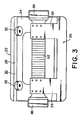
- reference numeral 20 designates a self-propelled truck constructed according to the present invention, which includes a substantially channel-shaped truck body 22 having a web 24 and a pair of flanges 26 and 27 integrally formed with the web 24.
- One flange 26 is longer than the other 27.
- Each flange 26, 27 has a wheel supporting ridge 28 integrally formed with its inner face to project toward each other and to extend along it.
- Each supporting ridge 28 has a pair of inclined surfaces 30 and 30 converging toward the other supporting ridge, thus providing a substantially V-shaped cross section to the supporting ridge.
- each pair of wheels 32 are rotatably supported on the inclined faces 30, 30, 30 and 30 of the supporting ridges 28 and 28 so that each pair of wheels 32 are respectively supported on a corresponding pair of inclined faces 30 and 30 so as to dispose rotation axes 34 and 34 thereof to cross at an acute angle 8 as shown in FIG. 1 and to be perpendicular to corresponding inclined faces 30 and 30. Further, rotation axes 34 of corresponding two pairs of the wheels 32 are disposed on a plane perpendicular to the longitudinal direction of the truck body 22 or parallel to the sheet of the drawing of FIG. 1.
- the longer flange 26 is provided at its edge with a substantially U-shaped brush plate 36 having two parallel brush mounting hands 38 and 38, each having six brushes 40 mounted on it.
- FIG. 1 illustrates a curved rail 42 which includes a yoke member 44, which is a rectangular iron plate, and a pair of rod-shaped sub-rail members 46 and 46 mounted on opposite lateral edges of the yoke member 44.
- the yoke member 44 is attached to a base 49 through two angle-shaped bracket members 48 and 48 although only one is shown in FIG. 1.
- Each sub-rail member 46 includes a wheel engaging head 50 having a substantially V-shaped or a trapezoidal cross section and a neck portion 52 perpendicularly projecting from the rear face of the head 50 and extending along it.
- Each head 50 has a pair of inclined wheel engaging faces 54 and 54 containing an angle ⁇ between them.
- sub-rails 46 may be fabricated by extrusion molding from an aluminum alloy.
- the sub-rails rails 46 and 46 are curved to correspond to a curved line CL of travel of the truck 20 as illustrated in FIGS. 4 or 7 and are fastened with screws at their neck portions to the opposite lateral edges of the yoke member 44 which is also curved according to the curved line CL.
- Wheels 32 and 32 in each pair engage with respective inclined engaging faces 54 and 54 of head 50 of a corresponding sub-rail member 46.
- the supporting ridges 28 and the heads 50 of the sub-rails 46 are disposed so that the two inclined faces 30 and 30 of each supporting ridges 28 and the two wheel engaging faces 54 and 54 of each sub-rail 46 converge on a plane P parallel to the line of travel of the truck 20.
- the yoke member 44 has three parallel trolley rails 60 mounted on its one side to electrically contact respective brushes 40 so that electric power is supplied from a power source (not shown) via the brushes 40 to a primary unit 62 of the linear induction motor which unit is mounted on the web 24 of the truck 22.
- the yoke member 44 has a secondary unit 64 of the linear induction motor, which is a rectangular aluminum or copper plate, bonded on the other side of the yoke member to face the primary unit 62.
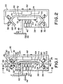
- FIG. 2 illustrates a straight rail 66 for a straight travel line SL of the truck 20.
- the straight rail 66 is integrally formed of a single rectangular plate by bending its opposite lateral edge portions in the same V-shaped cross section as the heads 50 of the sub-rails 46 so that the insides of its bent edges 68 and 68 face to each other.
- Each bent edge portion of the straight rail 66 has a pair of inclined wheel engaging faces 70 and 70 forming an angle equal to 0.
- the four pairs of wheels 32 also engage the wheel respective engaging faces 70 of the straight rail in the same manner as the wheel engaging faces 54 of the curved rail 42 as illustrated in FIG. 2.
- the flat portion 72 of the straight rail 66 serves as a secondary unit of the linear induction motor and has a rectangular yoke member 74 fastened with screws 76 to its one side facing the brushes 40.
- the yoke member 74 is supported to the base 49 through L-shaped bracket member 48 and has three parallel trolley rails 60 as in the yoke member 44 of the curved rail 42.
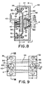
- the curved rail 42 may be jointed to the straight rail 66 by means of a pair of joint members 80 and 80 which are fastened with screws 76 to respective neck portions 52 of the sub-rails 46 and 46 of the curved rail 42 and to the yoke member 74 of the straight rail 66 as illustrated in FIGS. 5 and 6.
- FIG. 4 shows jointed portions of horizontally curved rail 82 and straight rail 66 and
- FIG. 7 shows jointed portions of vertically curved rail 84 and straight rail 66.
- reference numeral 86 indicates conventional shock absorbers mounted on the front and rear ends of the truck 20.
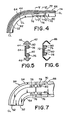
- FIGS. 8 and 9 illustrate a truck apparatus 90 of the same construction as that illustrated in FIGS. 1 to 3 except the structure of the truck 92, which includes a truck body 94, which is substantially a rectangular plate, and a pair of wheel frames 96 and 96 angularly movably attached to opposite ends of the truck body 94.
- the wheel frames 96 and 96 have the same profile as the truck body 22 in FIG. 1 but are much smaller in width W than the truck body 22 as clearly shown in FIG. 9.
- Each wheel frame 96 is provided at a center of its web 98 with a circular hole 100 formed through it.
- the truck body 94 has a pair of cylindrical projections 102 and 102 formed to perpendicularly project from opposite end portions of its one side.
- Each cylindrical projection 102 is placed-into a corresponding circular hole 100 to fit its circular shoulder 104 to an inner race 106 of a ball bearing 108 and is fastened to a securing disc 110 with three screws 112, with the result that it is secured to the inner race 106 so that the wheel frame 96 is rotatable about an axis A which perpendicularly passes through the plane P) at a point C intermediate wheels 32 of opposing pairs.
- the primary unit 62 of the linear induction motor is mounted on the other side of the truck body 94.
- the truck 92 when the truck 92 travels along the curved rail 42, the wheel frames 96 and 96 turn about the axes A so that wheels 32 are moved to positions shown by the phantom lines in FIG. 10 from the positions by the solid lines with the center lines thereof cl being directed to a center O of curvature of the curved rail 42.
- the truck 92 is capable of smoothly passing the curved rail 42 at a high speed without changing the distance D1 between wheels 32 of opposing pairs or the distance D2 between the sub-rails 46 and 46.
- the brushes 40 which are mounted to the wheel frames 96 and 96 also turn about the axis A from a position shown by the solid line to a position by the phantom line in FIG. 10 to extend along corresponding trolley rails 60, 60 and 60. Thus, uneven abrasion of the brushes 40 is prevented.
- the truck illustrated in FIGS. 12 and 13 is distinct from the truck in FIGS. 1-3 in that the secondary unit 64 of the linear induction motor is mounted on the truck while the primary unit 62 is mounted on the rail to face the secondary unit 64 although not shown.
- the reference numeral 120 designates a cover.
Landscapes
- Engineering & Computer Science (AREA)
- Mechanical Engineering (AREA)
- Chemical & Material Sciences (AREA)
- Combustion & Propulsion (AREA)
- Transportation (AREA)
- Architecture (AREA)
- Civil Engineering (AREA)
- Structural Engineering (AREA)
- Control Of Vehicles With Linear Motors And Vehicles That Are Magnetically Levitated (AREA)
- Platform Screen Doors And Railroad Systems (AREA)
Claims (4)
Applications Claiming Priority (4)
| Application Number | Priority Date | Filing Date | Title |
|---|---|---|---|
| JP1985047809U JPH0419041Y2 (fr) | 1985-03-29 | 1985-03-29 | |
| JP47809/85U | 1985-03-29 | ||
| JP11753285U JPS6226103U (fr) | 1985-07-31 | 1985-07-31 | |
| JP117532/85U | 1985-07-31 |
Publications (3)
| Publication Number | Publication Date |
|---|---|
| EP0197751A2 EP0197751A2 (fr) | 1986-10-15 |
| EP0197751A3 EP0197751A3 (en) | 1987-10-28 |
| EP0197751B1 true EP0197751B1 (fr) | 1990-07-18 |
Family
ID=26387989
Family Applications (1)
| Application Number | Title | Priority Date | Filing Date |
|---|---|---|---|
| EP86302407A Expired EP0197751B1 (fr) | 1985-03-29 | 1986-04-01 | Chariot ferroviaire à moteur linéaire |
Country Status (3)
| Country | Link |
|---|---|
| US (1) | US4860662A (fr) |
| EP (1) | EP0197751B1 (fr) |
| DE (1) | DE3672652D1 (fr) |
Families Citing this family (22)
| Publication number | Priority date | Publication date | Assignee | Title |
|---|---|---|---|---|
| ES2048256T3 (es) * | 1988-09-26 | 1994-03-16 | Fata Automation | Sistema transportador para mover materiales y articulos semielaborados. |
| CA1316139C (fr) * | 1988-10-31 | 1993-04-13 | Karl Hartlepp | Materiel de tri |
| GB2241478A (en) * | 1990-03-01 | 1991-09-04 | Norgren Martonair Ltd | Guide rail on a gantry loader |
| JPH0449841A (ja) * | 1990-06-14 | 1992-02-19 | Mitsubishi Electric Corp | 円筒形リニア搬送システム |
| US5222439A (en) * | 1990-11-30 | 1993-06-29 | Fata Automation S.P.A. | Material conveyance system using powered trolleys on a suspended rail |
| FI96127C (fi) * | 1992-05-07 | 1996-05-10 | Markus Roschier | Kuljetusjärjestelmä |
| US5492066A (en) * | 1993-07-30 | 1996-02-20 | Shinko Electric Co., Ltd. | Transport system |
| CA2180248A1 (fr) * | 1994-01-03 | 1995-07-13 | Kenneth E. Burkhalter | Piste pour materiel de manutention de tri |
| US5632589A (en) * | 1994-01-03 | 1997-05-27 | Symorex, Inc. | Apparatus for centralized mechanical and systems control in a material handling system |
| US5664503A (en) * | 1994-07-27 | 1997-09-09 | Shinko Electric Co., Ltd. | Container for linear motor driven transport system |
| NL1001322C2 (nl) * | 1995-09-29 | 1997-04-03 | Stork Rms Bv | Machinegestel voor de vleesverwerkende industrie en kokerprofiel. |
| SG74601A1 (en) * | 1996-11-15 | 2000-08-22 | Ishikawajima Harima Heavy Ind | System for traversing trolley |
| US6588579B2 (en) * | 2001-03-27 | 2003-07-08 | Jerry Taeger | Conveyor system accessories |
| US6591757B1 (en) * | 2001-12-26 | 2003-07-15 | Anorad Corporation | Motor driven high stability brake for linear motion systems |
| PT1575565E (pt) * | 2003-08-08 | 2010-03-03 | Biovail Lab Int Srl | Comprimido de libertação modificada de cloridrato de bupropiona |
| US20050275293A1 (en) * | 2004-06-10 | 2005-12-15 | Korea Electrotechnology Research Institute | System for integrating linear motion guide and linear induction motor |
| DE102010050760B4 (de) | 2010-11-10 | 2020-10-15 | Sew-Eurodrive Gmbh & Co Kg | Verfahren zur Herstellung unterschiedlicher Varianten von Schienen aus einem Bausatz und Anordnung mit einem auf einem Schienenteil bewegbaren Fahrzeug |
| US20140108028A1 (en) | 2012-10-12 | 2014-04-17 | Mckesson Automation Inc. | Apparatuses, systems, and methods for anticipating and delivering medications from a central pharmacy to a patient in a healthcare facility |
| US9150119B2 (en) * | 2013-03-15 | 2015-10-06 | Aesynt Incorporated | Apparatuses, systems, and methods for anticipating and delivering medications from a central pharmacy to a patient using a track based transport system |
| DE102014214107A1 (de) * | 2013-08-26 | 2015-02-26 | Robert Bosch Gmbh | Transportvorrichtung |
| US10029855B2 (en) * | 2016-09-23 | 2018-07-24 | Rockwell Automation Technologies, Inc. | Multi-rail/roller compliance system for independent mover products |
| JP7042990B1 (ja) * | 2021-06-17 | 2022-03-28 | 三菱電機株式会社 | リニア搬送装置 |
Family Cites Families (9)
| Publication number | Priority date | Publication date | Assignee | Title |
|---|---|---|---|---|
| BE411390A (fr) * | 1934-09-26 | |||
| CH361538A (de) * | 1957-07-29 | 1962-04-15 | Tourtellier S A R L Ets | Biegsame, als Laufschiene für Hängebahnen oder zur Aufnahme von Stromleitern für ortsveränderliche Entnahme elektrischen Stromes verwendbare Schiene |
| US3092039A (en) * | 1958-07-28 | 1963-06-04 | Gen Steel Ind Inc | Suspended railway systems |
| GB1055464A (en) * | 1962-09-14 | 1967-01-18 | John William Dark | Improvements in or relating to monorail systems |
| GB1278047A (en) * | 1968-06-26 | 1972-06-14 | Tracked Hovercraft Ltd | Linear induction motor rail |
| US3888185A (en) * | 1971-10-20 | 1975-06-10 | Robert Walsh | High speed transportation system |
| FR2373427A1 (fr) * | 1976-12-10 | 1978-07-07 | Monne Maxime | Perfectionnements apportes aux monorails et convoyeurs |
| DE2707379A1 (de) * | 1977-02-21 | 1978-08-24 | H J Krug M E A P | Steuerbare verteilerfoerderanlage |
| DE3030929C2 (de) * | 1980-08-16 | 1983-01-05 | Mannesmann AG, 4000 Düsseldorf | Laufkatze |
-
1986
- 1986-04-01 EP EP86302407A patent/EP0197751B1/fr not_active Expired
- 1986-04-01 DE DE8686302407T patent/DE3672652D1/de not_active Expired - Fee Related
-
1988
- 1988-09-07 US US07/241,758 patent/US4860662A/en not_active Expired - Fee Related
Also Published As
| Publication number | Publication date |
|---|---|
| US4860662A (en) | 1989-08-29 |
| EP0197751A2 (fr) | 1986-10-15 |
| DE3672652D1 (de) | 1990-08-23 |
| EP0197751A3 (en) | 1987-10-28 |
Similar Documents
| Publication | Publication Date | Title |
|---|---|---|
| EP0197751B1 (fr) | Chariot ferroviaire à moteur linéaire | |
| US6220174B1 (en) | Guidance system with a truck guided on a rail | |
| US4632038A (en) | Monorail vehicular system | |
| CN108840055B (zh) | 双向转动送货小车 | |
| JPH08108381A (ja) | 走行ロボットの走行案内装置 | |
| JP6427709B1 (ja) | 全方向移動台車 | |
| JP2772928B2 (ja) | 台車使用の搬送設備 | |
| ATE124006T1 (de) | Laufwerk für schienenfahrzeuge. | |
| JP2769133B2 (ja) | 送電線の作業用振り子型自走機 | |
| CN219859082U (zh) | 一种轻载型单轨rgv小车 | |
| JP2762759B2 (ja) | モノレール型搬送用電車のガイドレール装置 | |
| SU1311972A1 (ru) | Монорельсова транспортна система | |
| JP2754207B2 (ja) | 自走台車用のレール | |
| CN221292784U (zh) | 一种用于全方位快速运动的全向轮 | |
| JP2538204B2 (ja) | リニアモ−タ利用の搬送設備 | |
| JPS631305A (ja) | リニアモ−タカ−の可撓式台車構造 | |
| JPH0370670A (ja) | 軌道装置 | |
| JP2996582B2 (ja) | 台車屈曲走行装置 | |
| JPH079992Y2 (ja) | 電動スライディングウォール | |
| JP4010464B2 (ja) | 2トラックのガイドシステム | |
| JP2518192B2 (ja) | リニアモ―タ利用の搬送設備 | |
| JP2518194B2 (ja) | リニアモ―タ利用の搬送設備 | |
| JP3239939B2 (ja) | 自動倉庫システム | |
| JP2547077B2 (ja) | 移動体用のレール継ぎ構造 | |
| JPH05208730A (ja) | 荷搬送設備 |
Legal Events
| Date | Code | Title | Description |
|---|---|---|---|
| PUAI | Public reference made under article 153(3) epc to a published international application that has entered the european phase |
Free format text: ORIGINAL CODE: 0009012 |
|
| AK | Designated contracting states |
Kind code of ref document: A2 Designated state(s): DE FR GB |
|
| 17P | Request for examination filed |
Effective date: 19870203 |
|
| PUAL | Search report despatched |
Free format text: ORIGINAL CODE: 0009013 |
|
| AK | Designated contracting states |
Kind code of ref document: A3 Designated state(s): DE FR GB |
|
| 17Q | First examination report despatched |
Effective date: 19890223 |
|
| GRAA | (expected) grant |
Free format text: ORIGINAL CODE: 0009210 |
|
| AK | Designated contracting states |
Kind code of ref document: B1 Designated state(s): DE FR GB |
|
| REF | Corresponds to: |
Ref document number: 3672652 Country of ref document: DE Date of ref document: 19900823 |
|
| ET | Fr: translation filed | ||
| PLBE | No opposition filed within time limit |
Free format text: ORIGINAL CODE: 0009261 |
|
| STAA | Information on the status of an ep patent application or granted ep patent |
Free format text: STATUS: NO OPPOSITION FILED WITHIN TIME LIMIT |
|
| 26N | No opposition filed | ||
| PGFP | Annual fee paid to national office [announced via postgrant information from national office to epo] |
Ref country code: GB Payment date: 19980323 Year of fee payment: 13 |
|
| PGFP | Annual fee paid to national office [announced via postgrant information from national office to epo] |
Ref country code: FR Payment date: 19980409 Year of fee payment: 13 |
|
| PGFP | Annual fee paid to national office [announced via postgrant information from national office to epo] |
Ref country code: DE Payment date: 19980414 Year of fee payment: 13 |
|
| PG25 | Lapsed in a contracting state [announced via postgrant information from national office to epo] |
Ref country code: GB Free format text: LAPSE BECAUSE OF NON-PAYMENT OF DUE FEES Effective date: 19990401 |
|
| GBPC | Gb: european patent ceased through non-payment of renewal fee |
Effective date: 19990401 |
|
| PG25 | Lapsed in a contracting state [announced via postgrant information from national office to epo] |
Ref country code: FR Free format text: LAPSE BECAUSE OF NON-PAYMENT OF DUE FEES Effective date: 19991231 |
|
| REG | Reference to a national code |
Ref country code: FR Ref legal event code: ST |
|
| PG25 | Lapsed in a contracting state [announced via postgrant information from national office to epo] |
Ref country code: DE Free format text: LAPSE BECAUSE OF NON-PAYMENT OF DUE FEES Effective date: 20000201 |