EP0191908B1 - Stützmauer - Google Patents
Stützmauer Download PDFInfo
- Publication number
- EP0191908B1 EP0191908B1 EP85114011A EP85114011A EP0191908B1 EP 0191908 B1 EP0191908 B1 EP 0191908B1 EP 85114011 A EP85114011 A EP 85114011A EP 85114011 A EP85114011 A EP 85114011A EP 0191908 B1 EP0191908 B1 EP 0191908B1
- Authority
- EP
- European Patent Office
- Prior art keywords
- retaining wall
- shaped blocks
- shaped
- another
- wall according
- Prior art date
- Legal status (The legal status is an assumption and is not a legal conclusion. Google has not performed a legal analysis and makes no representation as to the accuracy of the status listed.)
- Expired - Lifetime
Links
- 230000003068 static effect Effects 0.000 claims description 14
- 230000001154 acute effect Effects 0.000 claims description 3
- 230000015572 biosynthetic process Effects 0.000 claims description 2
- 239000004575 stone Substances 0.000 description 30
- 239000002689 soil Substances 0.000 description 8
- 238000010276 construction Methods 0.000 description 5
- 238000006073 displacement reaction Methods 0.000 description 3
- 230000007704 transition Effects 0.000 description 3
- 230000000694 effects Effects 0.000 description 2
- 230000002349 favourable effect Effects 0.000 description 2
- 230000005484 gravity Effects 0.000 description 2
- 238000010521 absorption reaction Methods 0.000 description 1
- 239000011449 brick Substances 0.000 description 1
- 238000005034 decoration Methods 0.000 description 1
- 238000001035 drying Methods 0.000 description 1
- 238000004519 manufacturing process Methods 0.000 description 1
- 230000002787 reinforcement Effects 0.000 description 1
- 230000000630 rising effect Effects 0.000 description 1
Images


Classifications
-
- E—FIXED CONSTRUCTIONS
- E02—HYDRAULIC ENGINEERING; FOUNDATIONS; SOIL SHIFTING
- E02D—FOUNDATIONS; EXCAVATIONS; EMBANKMENTS; UNDERGROUND OR UNDERWATER STRUCTURES
- E02D29/00—Independent underground or underwater structures; Retaining walls
- E02D29/02—Retaining or protecting walls
- E02D29/025—Retaining or protecting walls made up of similar modular elements stacked without mortar
Definitions
- the invention relates to a retaining wall which is inclined relative to the vertical against a backfill of the soil and is made of shaped blocks of concrete arranged one above the other, the upper and lower sides of which are in positive engagement with each other and each have a projection or projection formed by step-like mutually offset bearing surfaces extending in parallel planes. have a correspondingly formed depression.
- Such a retaining wall is known from the publication "STOTTMURER AV BETONPRODUK-TER", Norges Betonindustriforbund, April 1981, p. 5 below. There, however, only one projection or only one reinforcement is provided on each top and bottom of a shaped block. From the same publication, but p. 6 above, a retaining wall is known with shaped stones, in which not all of the support surfaces extend parallel to one another, but whose support surfaces increase in distance from the imaginary central transverse planes of each shaped stone on its top side on the earth side and on its underside on the earth side lose weight.
- the object of the present invention is to create a retaining wall with large construction heights with the same size of the shaped blocks with great centering accuracy.
- the retaining wall according to the invention consists of shaped stones with three support surfaces which are staggered with respect to one another on the top and bottom, all of which run parallel to one another.
- shaped blocks arranged one above the other are centered twice within the retaining wall. Angling the stones when building the retaining wall is almost impossible. This is particularly due to the fact that the middle bearing surfaces are larger than the other bearing surfaces and the shoulders formed consequently have a certain minimum distance from one another.
- the further provided relative arrangement of the support surfaces to each other and to a central transverse plane of the shaped brick makes it possible to build the retaining wall in such a way that, in layers lying one above the other, several stones are arranged adjacent to one another transversely to the longitudinal extension of the retaining wall, the stones of the upper layer being opposite the stones of the lower layer are offset transversely to the longitudinal direction of the retaining wall and are still in positive engagement.
- the mutually offset bearing surfaces of the shaped blocks are connected to one another by an obliquely directed stop surface which drops towards the air side.
- this results in an enlargement of the statically effective bearing surface and is also maintained with slight relative displacements of the shaped blocks with respect to one another.
- Such slight relative displacements are often unavoidable in practice when installing the shaped blocks, i.e. when the retaining wall is put on.
- the support surfaces run right up to the front and back of the molded blocks, there is a statically effective support width that is only slightly smaller than the length of the molded block (dimension transverse to the longitudinal extension of the supporting wall).
- the static axis of a shaped stone or the retaining wall formed from it runs through the center of the support width.
- the support surfaces of the shaped stones are arranged at an oblique angle to the static axis, an obtuse angle being formed on the earth side and an acute angle on the air side relative to the static axis.
- the shaped blocks can be installed in the heavyweight retaining wall according to the invention in layers reversed with respect to the earth and air side.
- the formation of retaining walls with a graduated width or depth by arranging two or more shaped blocks in the direction transverse to the longitudinal extension of the retaining walls next to one another is particularly advantageous.
- the form stones that are adjacent in height are offset from one another and with mutual positive engagement with one another (toothing).
- the shaped blocks of the retaining wall are provided on the earth side and on the air side with head parts adjoining a support part formed by the support surfaces, which can be designed in a corresponding (different) manner for decoration, for better sound absorption or for interlocking with the ground.
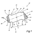
- the exemplary embodiments of shaped blocks shown in the drawings are used to manufacture retaining walls, namely heavy-weight drying retaining walls 20 with one-sided soil backfill 21.
- the retaining wall 20 is inclined towards the soil backfill Level arranged.
- the angle of the retaining wall 20 with respect to the horizontal is preferably between 60 ° and 70 °.
- shaped blocks 22 shown in the drawings form an upper side 23, an underside 24, an air-side end face 25 and a rear side 26 facing the soil backfill 21.
- Upper side 23 and underside 24 are designed to correspond to one another in all embodiments, in such a way that a appropriate, form-fitting superimposition of the shaped blocks 22 is ensured within the retaining wall 20.
- the top 23 and bottom 24 each consist of at least three bearing surfaces 27, 28 and 46 or 31, 32 and 51, which extend in mutually offset planes and always run parallel to one another.
- the bearing surface 28 facing the air side is offset from the ground-side bearing surface 27 downward - in the case of a horizontally lying molded block - to form a shoulder 29 with an inclined bearing surface 30 in the present case. This is sloping towards the air side, for example at an angle of approximately 45 ° to the two support surfaces 27 and 28.
- an earth-side support surface 31 and an air-side support surface 32 are also formed on the underside 24, which are also directed parallel to one another and parallel to the upper support surfaces 27, 28.
- the air-side bearing surface 32 is offset downwards in the same way, forming a shoulder 33, which is formed by an oblique stop surface 34.
- the shoulders with abutment surfaces on the top 23 and underside 24 give rise to depressions and recesses in the area of the superimposed surfaces of the shaped blocks 22, which interlock in a form-fitting and self-centering manner.
- the bearing surfaces 27, 28 and 46, as well as the stop surfaces 30 and 48 rest against the associated bearing surfaces 31, 32 and 51 or the stop surfaces 34 and 52 of the adjacent shaped stone.
- the support width b is decisive for the load capacity or permissible construction height of the retaining wall 20.
- a static axis 37 of the shaped block or the retaining wall extends in the middle of the support width b.
- the shaped blocks 22 are designed such that the static axis 37 is directed at an oblique angle to the upper and lower bearing surfaces 27 and 31, respectively, in such a way that an acute angle on the upper side of the shaped block 22 faces the air side is.
- the retaining wall 20 is preferably arranged inclined to the soil backfill 21 in an angular range of 60 ° to 70 ° of the static axis 37. The result of this is that the bearing surfaces 27, 28 and 46 and 31, 32 and 51 always slope downward to the soil backfill 21, while the stop surfaces 30, 34 and 48, 52 also extend downwards towards the air side. As a result, the aforementioned surfaces have a self-centering effect for the shaped stones 22 arranged one above the other.
- the support width b of the shaped blocks 22 or the retaining wall 20 as a whole is of particular importance statically.
- a force-resultant R resulting from the dead weight of the retaining wall 20 and the earth pressure due to the soil backfill 21 must run due to static regulations within a core cross section 38 or 39 de retaining wall 20, in each case in the area of the lower shaped stones 22.
- This static relevant core cross-section 38, 39 is 1/6 of the support width B. It extends centrally, that is to say with the same dimensions, on both sides of the static axis 37.
- a large support width b results in a correspondingly large core cross-section 38 or 39.
- the retaining wall 20 can have a correspondingly larger construction height.
- the shaped blocks 22 have more than two bearing surfaces and shoulders on the top 23 and bottom 24.
- a third bearing surface 46 is formed on the ground side, which extends according to the design principle of the shaped blocks in a horizontal position of the same at a higher level than the adjacent (larger) bearing surface 27.
- a shoulder 47 is formed with an obliquely directed stop surface 48
- an extension 41 which is trapezoidal in cross section, so that the bearing surface 46 is part of an edge-side projection 50 which is trapezoidal in cross section.
- a corresponding support surface 51 with stop surface 52 is formed on the underside, that is to say also with a shoulder 53.
- the top and bottom are correspondingly cascaded, rising on the top 23 toward the earth side.
- the middle bearing surface 27, 31 is large in relation to the approximately equally large bearing surfaces 28 and 46 or 32 and 51.
- the end face 25 consists of a head 40 with a triangular cross section with a lower round edge 44.
- the lower plane of the head 40 extends in extension of the support surface 32, but is not an effective component of the same, since the head 40 is outside the support width b lies.
- the cross-sectional areas of head 40 and shoulder 41 are of equal size, so that the statically interesting center of gravity S lies in the area of the static axis 37.
- Fig. 2 shows a shaped block 22 with mirror-symmetrical design such that the shaped blocks laid regardless of the front and back can be, since both sides are designed to match, in the present case arched, that is crowned.
- the shaped block is provided with three bearing surfaces 27, 28, 31, 32 and 46 and 51 on the top and bottom.
- the bearing surfaces 46 and 51 facing the soil backfill 21 have the same size as the air-side bearing surfaces 28 and 32.
- the height of the shoulders 29, 33, 47, 53 is also the same, so that a twisted laying of the shaped blocks by 180 ° within the Retaining wall 20 is possible.
- the center of gravity S lies on the static axis 37 in this same-sided design.
- the arrangement of always parallel support surfaces and, as in the exemplary embodiment shown, of stop surfaces arranged parallel to one another has the effect that even with slight relative displacements of the shaped blocks with respect to one another, as cannot be completely ruled out in practice when the retaining wall is erected, the effective support width b does not is changed in a noticeable way. There is only a gap of one or a few millimeters in the area of the heel 29 or 33. The stable, structurally perfect storage of the shaped stone is still preserved.
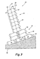
- FIG. 3 shows a shaped block 22 which corresponds in principle to the design according to FIG. 2.
- the front side and / or the rear side - in the exemplary embodiment shown the rear side 26 - are provided with a structured surface. These are grooves 64 which run in the longitudinal direction or horizontally and have an essentially trapezoidal cross section. These are separated from one another by appropriately designed ribs 65.
- Retaining walls of different external appearance can be formed from a shaped block 22 designed in this way, using only one type of shaped blocks (FIG. 3), and in fact by alternately laying the shaped blocks with the structured surfaces on the air side or on the earth side.
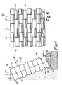
- Fig. 6 shows a retaining wall 20 with a variable effective cross section.
- a wall base 61 consists of a plurality of layers 43 of shaped stones 22 lying next to one another transversely to the longitudinal extension of the retaining wall 20, specifically in the embodiment with a third bearing surface 46 on the upper side, as in the exemplary embodiment in FIG. 1 or FIG. 2 and 3.
- the (smooth) backsides 26 face each other within the layers 43. This results in the area of the wall base 61 or a lower foundation layer 62, a support width b 2 , which results from the support surfaces of the two adjacent form stones 22 of the foundation layer 62.
- the stacked shaped blocks 22 are also in a mutual, positive engagement by the projections 50 on the one hand and by the shoulder 53 arranged opposite.
- the arrangement is such that the molded blocks on the opposite side are each reversed with respect to the top 23 and bottom 24. This results in a meandering interlocking of the stacked and adjacent stones in the area of a vertical central plane.
- Two adjacent shaped blocks of a layer 58 or 62 form a depression into which a projection 50 fits.
- the wall base 61 there is an upper wall part 63 made of layers 58, each with a shaped stone in the direction perpendicular to the level of the retaining wall 20.
- a statically favorable namely relatively wide core cross section 38 or 39 given.
- the lower molded block 22 of the upper wall part 63 is supported with the lower stop surface 34 on the upper stop surface 48 of the front molded block of the wall base 61. As a result, there is also a self-centering relative position of the shaped stones in this area.
- the number of layers 58 and 62 in the area of the wall base 61 is selected such that the lower core cross-section 39 is used on the basis of the specifications of the upper core cross-section 38 and the direction of the resultant R.
- the base layer 62 in this embodiment consists of three shaped stones 22 adjoining one another in the direction perpendicular to the plane of the retaining wall 20.
- the shaped stones in the sense of the embodiment of FIG Fig. 1 and the relative arrangement of the same also creates a self-centering support in the region of the transition from the upper wall part 63 to the wall base 61 and the layer 58 consisting of two shaped stones to the foundation layer 62.
- this retaining wall 20 made of shaped stones of the preferred embodiment of FIG. 1, there is an optimal interlocking interlocking of shaped stones in the area of the respective cross-sectional widening of the retaining wall, i.e. in the area of the lower layer 58 to the upper layer 43 and from the lower layer 43 to the foundation layer 62.
- Two shaped stones of one layer (here layer 43) are covered by a staggered shaped stone of an adjacent layer (here: layer 58 on the one hand and foundation layer 62 on the other hand), with engagement of the shoulders and depressions as a result of the cascade-shaped design.
- Such a wall is highly resilient or can be constructed with a large construction height.
- the shaped blocks can have any suitable or meaningful dimension.
- the total length of the shaped stone from the end face 25 to the rear side 26 is approximately 30 cm.
- the height of such a shaped block that is to say the distance between the support surfaces 27 and 31 from one another, is approximately 15 cm, for example.
- the shoulders, that is to say the distance between the parallel support surfaces, is 2.5 cm in one exemplary embodiment.
- the width of the small support surfaces 28, 32 ... is favorable at about 3.5 cm.
- the central transverse plane parallel to the larger bearing surfaces is referred to as the MQ (see e.g. Figures 1 and 2).
Priority Applications (4)
| Application Number | Priority Date | Filing Date | Title |
|---|---|---|---|
| AT85114011T ATE54694T1 (de) | 1985-02-18 | 1985-11-04 | Stuetzmauer. |
| FI860273A FI85529C (fi) | 1985-02-18 | 1986-01-21 | Mot bakomliggande markfyllning lutad stoedmur. |
| AU52765/86A AU587599B2 (en) | 1985-02-18 | 1986-01-28 | Shaped (concrete) block for retaining walls and also a retaining wall |
| JP61028065A JPH0745732B2 (ja) | 1985-02-18 | 1986-02-13 | 擁壁用コンクリート成形ブロックならびに擁壁 |
Applications Claiming Priority (2)
| Application Number | Priority Date | Filing Date | Title |
|---|---|---|---|
| DE3505530 | 1985-02-18 | ||
| DE19853505530 DE3505530A1 (de) | 1985-02-18 | 1985-02-18 | (beton-) formstein fuer stuetzmauern sowie stuetzmauer |
Publications (2)
| Publication Number | Publication Date |
|---|---|
| EP0191908A1 EP0191908A1 (de) | 1986-08-27 |
| EP0191908B1 true EP0191908B1 (de) | 1990-07-18 |
Family
ID=6262821
Family Applications (1)
| Application Number | Title | Priority Date | Filing Date |
|---|---|---|---|
| EP85114011A Expired - Lifetime EP0191908B1 (de) | 1985-02-18 | 1985-11-04 | Stützmauer |
Country Status (7)
| Country | Link |
|---|---|
| US (1) | US4711606A (da) |
| EP (1) | EP0191908B1 (da) |
| CA (1) | CA1245870A (da) |
| DE (2) | DE3505530A1 (da) |
| DK (1) | DK518485A (da) |
| IT (1) | IT1188391B (da) |
| NO (1) | NO174752C (da) |
Cited By (2)
| Publication number | Priority date | Publication date | Assignee | Title |
|---|---|---|---|---|
| WO2005113911A1 (de) | 2004-05-17 | 2005-12-01 | Sf-Kooperation Gmbh Beton-Konzepte | Stützmauer und formstein aus beton zur herstellung einer stützmauer |
| DE102004047823A1 (de) * | 2004-09-29 | 2006-03-30 | Sf-Kooperation Gmbh Beton-Konzepte | Mauer, insbesondere gegenüber der Lotrechten gegen eine Erdreich-Hinterfüllung geneigte Stützmauer |
Families Citing this family (44)
| Publication number | Priority date | Publication date | Assignee | Title |
|---|---|---|---|---|
| CA1298982C (en) * | 1988-02-25 | 1992-04-21 | Eugene M. Bender | Retaining wall construction and blocks therefore |
| DE3810934A1 (de) * | 1988-03-31 | 1989-10-12 | Rudolf Peter Gmbh & Co Kg Kies | Verfahren zum verwerten von rueck-restbeton von transportbeton |
| US4993206A (en) * | 1989-02-03 | 1991-02-19 | National Concrete Masonry Association | Interlocking building units and walls constructed thereby |
| DE3917500A1 (de) * | 1989-05-30 | 1990-12-06 | Sf Vollverbundstein | (beton-) formstein fuer stuetzmauern, form fuer die herstellung sowie stuetzmauer |
| US5294216A (en) | 1989-09-28 | 1994-03-15 | Anchor Wall Systems, Inc. | Composite masonry block |
| US5062610A (en) * | 1989-09-28 | 1991-11-05 | Block Systems Inc. | Composite masonry block mold for use in block molding machines |
| US5017049A (en) * | 1990-03-15 | 1991-05-21 | Block Systems Inc. | Composite masonry block |
| US5044833A (en) * | 1990-04-11 | 1991-09-03 | Wilfiker William K | Reinforced soil retaining wall and connector therefor |
| US5120164A (en) * | 1991-05-24 | 1992-06-09 | Tony Iacocca | Retaining wall and block for constructing the same |
| NZ257237A (en) | 1992-10-06 | 1997-05-26 | Anchor Wall Syst | Masonry block enabling construction of curved or serpentine walls and a retaining wall made from the blocks and mould assembly for making such blocks |
| US5704183A (en) | 1992-10-06 | 1998-01-06 | Anchor Wall Systems, Inc. | Composite masonry block |
| US5490363A (en) | 1992-10-06 | 1996-02-13 | Anchor Wall Sytems, Inc. | Composite masonry block |
| US5484236A (en) * | 1993-10-25 | 1996-01-16 | Allan Block Corporation | Method of forming concrete retaining wall block |
| US5425600A (en) * | 1994-01-21 | 1995-06-20 | Gordon; Bradford C. | Drainage block feedthrough for assembly of walls constructed of specialized retaining blocks |
| CA2143278A1 (en) * | 1994-04-14 | 1995-10-15 | Louis Arvai | Concrete gabions |
| EP0828899B1 (en) * | 1995-06-02 | 2003-08-06 | Novabrick International Inc. | A block for the mortarless construction of a wall |
| US5913790A (en) * | 1995-06-07 | 1999-06-22 | Keystone Retaining Wall Systems, Inc. | Plantable retaining wall block |
| US5601384A (en) * | 1995-06-07 | 1997-02-11 | Keystone Retaining Wall Systems, Inc. | Plantable retaining wall |
| USD387434S (en) * | 1996-01-03 | 1997-12-09 | Keystone Retaining Wall Systems, Inc. | Front face of a plantable retaining wall block |
| US5765970A (en) * | 1996-06-17 | 1998-06-16 | Fox; James C. | Plastic retaining wall construction |
| US5879603A (en) | 1996-11-08 | 1999-03-09 | Anchor Wall Systems, Inc. | Process for producing masonry block with roughened surface |
| US6082057A (en) | 1996-11-08 | 2000-07-04 | Anchor Wall Systems, Inc. | Splitting technique |
| US6029943A (en) | 1996-11-08 | 2000-02-29 | Anchor Wall Systems, Inc. | Splitting technique |
| USD458693S1 (en) | 1996-11-08 | 2002-06-11 | Anchor Wall Systems, Inc. | Retaining wall block |
| USD415845S (en) * | 1997-02-11 | 1999-10-26 | Staten Bobby L | Decorative edging stone |
| USD409312S (en) * | 1997-02-11 | 1999-05-04 | Staten Bobby L | Decorative landscape stone |
| USD445512S1 (en) | 1997-10-27 | 2001-07-24 | Anchor Wall Systems, Inc. | Retaining wall block |
| USD430680S (en) * | 1999-01-15 | 2000-09-05 | Handy-Stone Corporation | Concrete block |
| DE19905842A1 (de) * | 1999-02-12 | 2000-08-17 | Karl Weber Betonwerk Gmbh & Co | Palisade |
| EP1153173A1 (en) * | 1999-02-12 | 2001-11-14 | Shaw Technologies Inc. | Interlocking segmental retaining wall |
| DE29902467U1 (de) * | 1999-02-12 | 2000-06-29 | Karl Weber Betonwerk Gmbh & Co | Palisade |
| US6267533B1 (en) * | 1999-08-18 | 2001-07-31 | George S. Bourg | Erosion control system |
| US6250850B1 (en) | 1999-08-19 | 2001-06-26 | Rockwood Retaining Walls, Inc. | Block with multifaceted bottom surface |
| DE10002390A1 (de) * | 2000-01-20 | 2001-07-26 | Sf Koop Gmbh Beton Konzepte | Formstein aus Beton, Form und Verfahren zur Herstellung eines Formsteins |
| EP1493869A1 (de) * | 2003-06-30 | 2005-01-05 | Martin Mannhart | Elementblockmauer und Bauelement zum Erstellen einer solchen Mauer |
| AU2005309711A1 (en) * | 2004-11-24 | 2006-06-01 | Contech Technologies, Inc. | Retaining wall block with face connection |
| DE102005050456A1 (de) * | 2005-10-19 | 2007-04-26 | Sf-Kooperation Gmbh Beton-Konzepte | Stützwand |
| NZ578903A (en) * | 2007-02-12 | 2012-03-30 | Kingspan Res & Dev Ltd | Composite cladding panel including blocks and insulating material |
| US7849656B2 (en) * | 2008-04-18 | 2010-12-14 | Anchor Wall Systems, Inc. | Dry cast block arrangement and methods |
| PT2319048E (pt) | 2008-08-22 | 2015-11-25 | Veritas Medical Solutions Llc | Bloco de alvenaria com superfícies continuamente curvadas |
| PT105009A (pt) * | 2010-03-09 | 2011-09-09 | Antonio Jose Vieira Da Cunha | Bloco para construção de sistemas de fundação e método para construir muros com o referido bloco |
| US9677271B2 (en) | 2015-10-08 | 2017-06-13 | Anchor Wall Systems, Inc. | Concrete unit and methods |
| PL422755A1 (pl) * | 2017-09-05 | 2019-03-11 | Przedsiębiorstwo Realizacyjne Inora - Inorganic Activities Spółka Z Ograniczoną Odpowiedzialnością | Bloczek budowlany |
| US20190368152A1 (en) * | 2018-05-30 | 2019-12-05 | Earth Wall Products, Llc | Method for making modular retaining wall block with lever extension using cmu block machine |
Citations (1)
| Publication number | Priority date | Publication date | Assignee | Title |
|---|---|---|---|---|
| EP0181230A2 (en) * | 1984-11-08 | 1986-05-14 | John Watson Crighton | Improvements in or relating to building blocks |
Family Cites Families (18)
| Publication number | Priority date | Publication date | Assignee | Title |
|---|---|---|---|---|
| US789730A (en) * | 1903-01-30 | 1905-05-16 | Henry L Hinton | Tile building-block and method of forming same. |
| FR376718A (fr) * | 1907-04-12 | 1907-08-19 | Eugene Fichefet | Revetement de talus et de berges |
| CA744126A (en) * | 1961-11-13 | 1966-10-11 | R. Svee Hallbjorn | Block for making protecting covers on slopes of moles and breakwaters |
| US3488964A (en) * | 1967-11-27 | 1970-01-13 | Giken Kogyo Kk | Concrete block |
| DE1912155A1 (de) * | 1969-03-11 | 1970-11-05 | Fischer Karl | Verbundstein |
| JPS5056004A (da) * | 1973-09-14 | 1975-05-16 | ||
| DE7520030U (de) * | 1975-06-24 | 1977-06-16 | Sf-Vollverbundstein-Kooperation Gmbh, 2820 Bremen | Bauelementensatz zur erstellung von stuetzwaenden |
| DE2731228C2 (de) * | 1977-07-11 | 1983-02-03 | Sf-Vollverbundstein-Kooperation Gmbh, 2820 Bremen | Formstein aus Beton für die Herstellung einer Stützmauer sowie aus derartigen Formsteinen hergestellte Stützmauer |
| EP0021449B1 (de) * | 1979-06-29 | 1984-06-27 | QUADIE-Bausysteme GmbH | Bauwerk in der Art einer Stützwand od. dgl. |
| DE8012113U1 (de) * | 1980-05-03 | 1980-07-31 | Gimmler, Helmut, 6618 Wadern-Bardenbach | Boeschungsformstein |
| DE3017064C2 (de) * | 1980-05-03 | 1984-04-05 | Gimmler, Luise Maria, 6618 Wadern-Bardenbach | Böschungsformstein |
| DE3163580D1 (en) * | 1981-03-10 | 1984-06-20 | Rolf Scheiwiller | Assembly of blocks for constructing walls |
| US4512685A (en) * | 1981-09-08 | 1985-04-23 | Ameron, Inc. | Mortarless retaining-wall system and components thereof |
| CA1182295A (en) * | 1982-08-16 | 1985-02-12 | Angelo Risi | Retaining wall system |
| AT391507B (de) * | 1983-01-24 | 1990-10-25 | Rausch Peter | Baustein |
| FR2544764B1 (fr) * | 1983-04-19 | 1985-12-06 | Rech Ste Civile Et | Element de soutenement pour la confection de talus de retenue et similaires |
| US4601148A (en) * | 1983-06-24 | 1986-07-22 | Angelo Risi | Module for walls and free standing structure |
| CH663437A5 (en) * | 1984-06-21 | 1987-12-15 | Carl Schiffer | Slope block |
-
1985
- 1985-02-18 DE DE19853505530 patent/DE3505530A1/de not_active Withdrawn
- 1985-11-04 DE DE8585114011T patent/DE3578765D1/de not_active Expired - Fee Related
- 1985-11-04 EP EP85114011A patent/EP0191908B1/de not_active Expired - Lifetime
- 1985-11-11 DK DK518485A patent/DK518485A/da not_active Application Discontinuation
- 1985-11-11 NO NO854476A patent/NO174752C/no not_active IP Right Cessation
-
1986
- 1986-01-24 CA CA000500289A patent/CA1245870A/en not_active Expired
- 1986-01-31 US US06/824,804 patent/US4711606A/en not_active Expired - Lifetime
- 1986-02-14 IT IT19422/86A patent/IT1188391B/it active
Patent Citations (1)
| Publication number | Priority date | Publication date | Assignee | Title |
|---|---|---|---|---|
| EP0181230A2 (en) * | 1984-11-08 | 1986-05-14 | John Watson Crighton | Improvements in or relating to building blocks |
Non-Patent Citations (1)
| Title |
|---|
| "Stottemurer AV Betonprodukter", Norges Betonindustriforbund, April 1981 * |
Cited By (2)
| Publication number | Priority date | Publication date | Assignee | Title |
|---|---|---|---|---|
| WO2005113911A1 (de) | 2004-05-17 | 2005-12-01 | Sf-Kooperation Gmbh Beton-Konzepte | Stützmauer und formstein aus beton zur herstellung einer stützmauer |
| DE102004047823A1 (de) * | 2004-09-29 | 2006-03-30 | Sf-Kooperation Gmbh Beton-Konzepte | Mauer, insbesondere gegenüber der Lotrechten gegen eine Erdreich-Hinterfüllung geneigte Stützmauer |
Also Published As
| Publication number | Publication date |
|---|---|
| CA1245870A (en) | 1988-12-06 |
| NO174752C (no) | 1994-06-29 |
| NO854476L (no) | 1986-08-19 |
| NO174752B (no) | 1994-03-21 |
| IT1188391B (it) | 1988-01-07 |
| DK518485A (da) | 1986-08-19 |
| DE3505530A1 (de) | 1986-08-21 |
| DE3578765D1 (de) | 1990-08-23 |
| EP0191908A1 (de) | 1986-08-27 |
| IT8619422A0 (it) | 1986-02-14 |
| IT8619422A1 (it) | 1987-08-14 |
| US4711606A (en) | 1987-12-08 |
| DK518485D0 (da) | 1985-11-11 |
Similar Documents
| Publication | Publication Date | Title |
|---|---|---|
| EP0191908B1 (de) | Stützmauer | |
| DE2731228C2 (de) | Formstein aus Beton für die Herstellung einer Stützmauer sowie aus derartigen Formsteinen hergestellte Stützmauer | |
| AT391507B (de) | Baustein | |
| DE3502793A1 (de) | Plattenelement zum verlegen auf dem erdboden oder aehnlichen flaechen | |
| WO2005113911A1 (de) | Stützmauer und formstein aus beton zur herstellung einer stützmauer | |
| EP0428762B1 (de) | Plattenförmiger Pflasterstein | |
| DE3538124A1 (de) | Formstein | |
| DE1811932A1 (de) | Betonbalken,insbesondere fuer Raumgitter und Stuetzmauern | |
| EP0517117B1 (de) | Pflanzkasten aus Holz | |
| DE2102050A1 (de) | Bodenplatte zur Erstellung von mobilen Fußböden und Podesten | |
| DE2532520C3 (de) | Schutzvorrichtung, insbesondere Schallschutzeinrichtung und Böschungsbefestigung für Strassen, bestehend aus vorgefertigten Bauteilen aus Kunststein, Beton o.dgl | |
| EP0058925A1 (de) | Bauteilsatz für eine als Gitterwand ausgebildete Stützmauer, Lärmschutzwand oder dergleichen | |
| DE3320034A1 (de) | Bauelement zum herstellen eines tragbelages oder dgl. | |
| EP1131506B1 (de) | Baustein und daraus gebildetes mauerwerk | |
| WO2002025033A1 (de) | Stufenstein für eine treppe und daraus gebildete treppe | |
| DE19960320A1 (de) | Pflastersteinsystem | |
| DE3510914A1 (de) | Doppelstein | |
| EP3967827B1 (de) | Treppenstufenbetonfertigteil | |
| EP0952260B1 (de) | Beton-Formstein-System | |
| EP1835077A1 (de) | Stein zur Errichtung von Schwergewichtsmauern | |
| DE102021121703A1 (de) | Drainagevorrichtung, Drainagesystem, Verfahren zu einer Montage des Drainagesystems und Verfahren zu einer Herstellung der Drainagevorrichtung | |
| DE3517337A1 (de) | Formsteine fuer eine treppenartige boeschungswand sowie verfahren zum herstellen einer solchen boeschungswand | |
| DE3144888A1 (de) | Daemmplatte zur waerme- und trittschallisolierung | |
| DE3033650A1 (de) | Schallschutzwand | |
| EP2331752A1 (de) | Erdreichabdeckung aus formsteinen |
Legal Events
| Date | Code | Title | Description |
|---|---|---|---|
| PUAI | Public reference made under article 153(3) epc to a published international application that has entered the european phase |
Free format text: ORIGINAL CODE: 0009012 |
|
| AK | Designated contracting states |
Kind code of ref document: A1 Designated state(s): AT BE CH DE FR GB IT LI NL SE |
|
| 17P | Request for examination filed |
Effective date: 19870203 |
|
| 17Q | First examination report despatched |
Effective date: 19880316 |
|
| 17Q | First examination report despatched |
Effective date: 19881118 |
|
| GRAA | (expected) grant |
Free format text: ORIGINAL CODE: 0009210 |
|
| AK | Designated contracting states |
Kind code of ref document: B1 Designated state(s): AT BE CH DE FR GB IT LI NL SE |
|
| REF | Corresponds to: |
Ref document number: 54694 Country of ref document: AT Date of ref document: 19900815 Kind code of ref document: T |
|
| GBT | Gb: translation of ep patent filed (gb section 77(6)(a)/1977) | ||
| REF | Corresponds to: |
Ref document number: 3578765 Country of ref document: DE Date of ref document: 19900823 |
|
| ITF | It: translation for a ep patent filed |
Owner name: STUDIO JAUMANN |
|
| ET | Fr: translation filed | ||
| PLBE | No opposition filed within time limit |
Free format text: ORIGINAL CODE: 0009261 |
|
| STAA | Information on the status of an ep patent application or granted ep patent |
Free format text: STATUS: NO OPPOSITION FILED WITHIN TIME LIMIT |
|
| 26N | No opposition filed | ||
| ITTA | It: last paid annual fee | ||
| PGFP | Annual fee paid to national office [announced via postgrant information from national office to epo] |
Ref country code: NL Payment date: 19941130 Year of fee payment: 10 |
|
| PGFP | Annual fee paid to national office [announced via postgrant information from national office to epo] |
Ref country code: BE Payment date: 19950104 Year of fee payment: 10 |
|
| EAL | Se: european patent in force in sweden |
Ref document number: 85114011.1 |
|
| PG25 | Lapsed in a contracting state [announced via postgrant information from national office to epo] |
Ref country code: BE Effective date: 19951130 |
|
| BERE | Be: lapsed |
Owner name: SF-VOLLVERBUNDSTEIN-KOOPERATION G.M.B.H. Effective date: 19951130 |
|
| PG25 | Lapsed in a contracting state [announced via postgrant information from national office to epo] |
Ref country code: NL Effective date: 19960601 |
|
| NLV4 | Nl: lapsed or anulled due to non-payment of the annual fee |
Effective date: 19960601 |
|
| PGFP | Annual fee paid to national office [announced via postgrant information from national office to epo] |
Ref country code: SE Payment date: 20001106 Year of fee payment: 16 |
|
| PGFP | Annual fee paid to national office [announced via postgrant information from national office to epo] |
Ref country code: FR Payment date: 20001110 Year of fee payment: 16 |
|
| PG25 | Lapsed in a contracting state [announced via postgrant information from national office to epo] |
Ref country code: SE Free format text: LAPSE BECAUSE OF NON-PAYMENT OF DUE FEES Effective date: 20011105 |
|
| REG | Reference to a national code |
Ref country code: GB Ref legal event code: IF02 |
|
| EUG | Se: european patent has lapsed |
Ref document number: 85114011.1 |
|
| PG25 | Lapsed in a contracting state [announced via postgrant information from national office to epo] |
Ref country code: FR Free format text: LAPSE BECAUSE OF NON-PAYMENT OF DUE FEES Effective date: 20020730 |
|
| REG | Reference to a national code |
Ref country code: FR Ref legal event code: ST |
|
| REG | Reference to a national code |
Ref country code: FR Ref legal event code: ST |
|
| PGFP | Annual fee paid to national office [announced via postgrant information from national office to epo] |
Ref country code: DE Payment date: 20021113 Year of fee payment: 18 Ref country code: AT Payment date: 20021113 Year of fee payment: 18 |
|
| PG25 | Lapsed in a contracting state [announced via postgrant information from national office to epo] |
Ref country code: AT Free format text: LAPSE BECAUSE OF NON-PAYMENT OF DUE FEES Effective date: 20031104 |
|
| PG25 | Lapsed in a contracting state [announced via postgrant information from national office to epo] |
Ref country code: DE Free format text: LAPSE BECAUSE OF NON-PAYMENT OF DUE FEES Effective date: 20040602 |
|
| PGFP | Annual fee paid to national office [announced via postgrant information from national office to epo] |
Ref country code: GB Payment date: 20041104 Year of fee payment: 20 |
|
| PGFP | Annual fee paid to national office [announced via postgrant information from national office to epo] |
Ref country code: CH Payment date: 20041117 Year of fee payment: 20 |
|
| PG25 | Lapsed in a contracting state [announced via postgrant information from national office to epo] |
Ref country code: GB Free format text: LAPSE BECAUSE OF EXPIRATION OF PROTECTION Effective date: 20051103 |
|
| REG | Reference to a national code |
Ref country code: GB Ref legal event code: PE20 |
|
| REG | Reference to a national code |
Ref country code: CH Ref legal event code: PL |