EP0191908A1 - Stützmauer - Google Patents
Stützmauer Download PDFInfo
- Publication number
- EP0191908A1 EP0191908A1 EP85114011A EP85114011A EP0191908A1 EP 0191908 A1 EP0191908 A1 EP 0191908A1 EP 85114011 A EP85114011 A EP 85114011A EP 85114011 A EP85114011 A EP 85114011A EP 0191908 A1 EP0191908 A1 EP 0191908A1
- Authority
- EP
- European Patent Office
- Prior art keywords
- shaped
- retaining wall
- support
- stones
- bearing surface
- Prior art date
- Legal status (The legal status is an assumption and is not a legal conclusion. Google has not performed a legal analysis and makes no representation as to the accuracy of the status listed.)
- Granted
Links
- 239000004575 stone Substances 0.000 claims abstract description 50
- 239000002689 soil Substances 0.000 claims description 10
- 238000004519 manufacturing process Methods 0.000 claims description 3
- 230000015572 biosynthetic process Effects 0.000 claims description 2
- 239000011449 brick Substances 0.000 claims 1
- 230000000284 resting effect Effects 0.000 abstract 1
- 230000003068 static effect Effects 0.000 description 14
- 230000005484 gravity Effects 0.000 description 6
- 238000010276 construction Methods 0.000 description 4
- 238000006073 displacement reaction Methods 0.000 description 3
- 230000000694 effects Effects 0.000 description 3
- 230000007704 transition Effects 0.000 description 3
- 230000001154 acute effect Effects 0.000 description 2
- 230000002349 favourable effect Effects 0.000 description 2
- 230000000630 rising effect Effects 0.000 description 2
- 238000010521 absorption reaction Methods 0.000 description 1
- 238000005034 decoration Methods 0.000 description 1
Images


Classifications
-
- E—FIXED CONSTRUCTIONS
- E02—HYDRAULIC ENGINEERING; FOUNDATIONS; SOIL SHIFTING
- E02D—FOUNDATIONS; EXCAVATIONS; EMBANKMENTS; UNDERGROUND OR UNDERWATER STRUCTURES
- E02D29/00—Independent underground or underwater structures; Retaining walls
- E02D29/02—Retaining or protecting walls
- E02D29/025—Retaining or protecting walls made up of similar modular elements stacked without mortar
Definitions
- the invention relates to a shaped block made of concrete for the production of a retaining wall inclined with respect to the vertical against a soil backfill from layered shaped blocks which are in positive engagement with one another by means of projections and depressions on the top and bottom. Furthermore, the invention relates to a retaining wall made of such shaped stones.
- the present invention aims to further develop and improve molded blocks of the above design and retaining walls made therefrom in technical and aesthetic terms.
- larger structural heights of the retaining walls are to be made possible with the same size of the shaped blocks and the same technical requirements.
- the shaped block according to the invention is characterized in that the top and bottom of the same each have at least two staggered, mutually parallel support surfaces.
- the offset of the bearing surfaces on the top and bottom sides is formed in such a way that the air-side bearing surfaces are at a lower level than the earth-side bearing surfaces.
- the mutually offset bearing surfaces are connected to one another by an obliquely directed stop surface that drops towards the air side.
- This configuration of the shaped stones surprisingly achieves an enlargement of the statically effective support surface and also maintains them with slight relative displacements of the shaped stones with respect to one another. Such slight relative displacements are often unavoidable in practice when installing the shaped blocks, i.e. when the retaining wall is put on.
- the resulting statically effective support width is only slightly smaller than the length of the molded block (dimension transverse to the longitudinal extension of the supporting wall).
- the static axis of a shaped stone or the retaining wall formed from it runs through the center of the support width.
- the support surfaces of the shaped stones are arranged at an oblique angle to the static axis, an obtuse angle being formed on the earth side and an acute angle on the air side relative to the static axis.
- a molded block is particularly advantageous in which three or more parallel bearing surfaces are formed on the upper side - and correspondingly on the lower side - by which the earth-side extends in a higher plane than the middle bearing surface and this in turn in a higher plane than the air-side, the earth-side and the air-side bearing surface being approximately the same size and the mean bearing surface being considerably larger than the earth-side and the air-side.
- the three (or more) support surfaces are thus cascaded - rising from the air side to the earth side - with one another with angled stop surfaces between adjacent support surfaces.
- the shaped blocks can be installed side-by-side with respect to the earth and air side.
- the formation of retaining walls with a graduated width or depth by arranging two or more shaped blocks in the direction transverse to the longitudinal extent of the retaining walls next to one another is particularly advantageous.
- lower wall bases are formed, which have a step-like cross section, which considerably increase the construction height and the load-bearing capacity of the retaining wall.
- the form stones that are adjacent in height are offset from one another and with mutual positive engagement with one another (toothing).
- the shaped blocks are provided on the earth side and on the air side with head parts which adjoin a support part formed by the support surfaces and which can be designed in a corresponding (different) manner for decoration, for better sound absorption or for interlocking with the ground.
- the exemplary embodiments of shaped blocks shown in the drawings are used for the production of retaining walls, namely heavyweight dry retaining walls 20 with one-sided soil backfill 21.
- the retaining wall 20 is arranged in a plane inclined against the soil backfill.
- the angle of the retaining wall 20 with respect to the horizontal is preferably between 60 ° and 70 °.
- the exemplary embodiments of shaped stones 22 shown in the drawings form an upper side 23, an underside 24, an air-side end face 25 and a rear side 26 facing the soil backfill 21.
- the upper side 23 and underside 24 are designed to correspond to one another in all embodiments, in such a way that a appropriate, form-fitting superimposition of the shaped blocks 22 is ensured within the retaining wall 20.
- the top 23 and bottom 24 consist of at least two support surfaces 27 and 28, which extend in mutually offset planes and always run parallel to one another.
- the support surface 28 facing the air side is offset from the ground-side support surface 27 downward - with horizontally lying molded block - to form a shoulder 29 with an oblique stop surface 30 in the present case. This is arranged sloping towards the air side, for example at an angle of approximately 45 ° to the two support surfaces 27 and 28.
- an earth-side bearing surface 31 and an air-side bearing surface 32 are also formed on the underside 24, which are also directed parallel to one another and parallel to the upper bearing surfaces 27, 28.
- the air-side bearing surface 32 is offset downwards in the same way, forming a shoulder 33, which is formed by an oblique stop surface 34.
- the shoulders with abutment surfaces on the top 23 and underside 24 give rise to depressions and recesses in the area of the superimposed surfaces of the shaped blocks 22, which interlock in a form-fitting and self-centering manner.
- a support width b statically comes into effect, which corresponds to the sum of the support and stop surfaces (see, for example, FIG. 6).
- the support width b is decisive for the load capacity or permissible construction height of the retaining wall 20.
- a static axis 37 of the shaped block or the retaining wall extends in the middle of the support width b.
- the shaped blocks 22 are designed such that the static axis 37 is directed at an oblique angle to the upper and lower bearing surfaces 27 and 31, respectively, in such a way that an acute angle on the upper side of the shaped block 22 faces the air side is.
- the retaining wall 20 is preferably arranged inclined to the soil backfill 21 in an angular range of 60 ° to 70 ° of the static axis 37. The result of this is that the bearing surfaces 27 and 28 and 31 and 32 always slope towards the backfill 21, while the stop surfaces 30, 34 also extend towards the air side. As a result, the aforementioned surfaces have a self-centering effect for the shaped stones 22 arranged one above the other.
- the support width b of the shaped blocks 22 or the retaining wall 20 as a whole is of particular importance statically.
- a force resultant R resulting from the dead weight of the retaining wall 20 and the earth pressure due to the soil backfilling 21 must run due to static regulations within a core cross section 38 or 39 of the retaining wall 20, in each case in the area of the lower shaped stones 22.
- This is static relevant core cross section 38, 39 is 1/6 of the support width b. It extends in the middle, ie with the same dimensions, on both sides of the static axis 37.
- a large support width b results in a correspondingly large core cross section 38 or 39.
- the retaining wall 20 can have a correspondingly larger construction height.
- a statically interesting quantity is also the center of gravity S of the shaped block 22.
- the width of the support is shown on the air side b protruding head 40 is formed, which is limited on the outside by the end face 25.
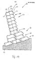
- the weight or the mass of this head 40 (hatched in FIG. 1) causes the center of gravity S to shift towards the air side.
- a smaller extension 41 which is triangular in cross section in the embodiment of FIG. 1, acts in the region of the earth side.
- the projection 41 is of the same size as the head 40.
- a step 42 is formed in the area of the rear side 26, which increases the roughness of the shaped block on the one hand and serves as a handle for grasping the same on the other.
- the shaped stones 22 can be provided on the top 23 and bottom 24 with more than two bearing surfaces and shoulders.
- a further, third support surface 46 is formed on the ground side, which extends according to the design principle of the shaped blocks in a horizontal position of the same at a higher level than the adjacent (larger) support surface 27.
- a shoulder 47 is formed with an oblique direction Stop surface 48.
- a shoulder 41 with a trapezoidal cross section adjoins the earth side, so that the bearing surface 46 is part of an edge-side projection 50 with a trapezoidal cross section.
- a corresponding support surface 51 with stop surface 52 is formed on the underside, that is to say also with a shoulder 53.
- the top and bottom are correspondingly cascaded, rising on the top 23 toward the earth side.
- the middle bearing surface 27, 31 is large in relation to the bearing surfaces 28 and 46 or 32 and 51 of the same size.
- the end face 25 consists of a head 40 with a triangular cross section with a lower round edge 44.
- the lower plane of the head 40 extends in extension of the support surface 32, but is not an effective component of the same, since the head 40 is outside the support width b lies.
- the cross-sectional areas of head 40 and shoulder 41 are of equal size, so that the center of gravity S lies in the area of the static axis 37.
- Fig. 7 shows a variant in which three support surfaces 27, 28 and 46 are also formed on the top.
- the latter bearing surface 46 is of greater length than in the previously described embodiment.
- the greater number of paragraphs 29, 33, 47, 53 on the top 23 and bottom 24 causes the molded blocks to be more closely interlinked.
- the smooth-surface back 26 of these shaped stones is provided with a molded-in depression 54, which can serve as a recess in the handle.
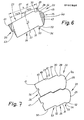
- Fig. 8 shows a shaped block 22 with mirror-symmetrical design such that the shaped blocks can be laid regardless of the front and back, since both sides are designed to match, in the present case arcuate, that is, spherical.
- the shaped block is provided with three bearing surfaces 27, 28, 31, 32 and 46 and 51 on the top and bottom.
- the bearing surfaces 46 and 51 facing the soil backfill 21 have the same size as the air-side bearing surfaces 28 and 32.
- the heels 29, 33, 47, 53 are also the same, so that a twisted laying of the shaped blocks by 180 ° within the Retaining wall 20 is possible.
- the center of gravity S lies on the static axis 37 in this same-sided design.
- FIG. 9 shows a shaped block 22 which corresponds in principle to the design according to FIG. 8. This means that the head 40 and shoulder 41 are formed essentially in agreement, so that this molded block can be installed reversed.
- the front side and / or the rear side - in the exemplary embodiment shown the rear side 26 - are provided with a structured surface. These are grooves 64 which run in the longitudinal direction or horizontally and have an essentially trapezoidal cross section. These are separated from one another by appropriately designed ribs 65.
- Retaining walls of different external appearance can be formed from a shaped block 22 designed in this way, using only one type of shaped blocks (FIG. 9), and in fact by alternately laying the shaped blocks with the structured surfaces on the air side or on the earth side.
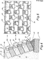
- FIG. 4 and 5 show the arrangement of the shaped stones 22 in a customarily constructed, plantable retaining wall 20 on a continuous concrete foundation 56 with a wedge-shaped compensating piece 57 for determining the inclination.
- the shaped blocks 22 are spaced from one another and “on a gap”, so that gaps 59 are created for planting. In the present design of the shaped blocks, this enables the soil to be brought up to the end face 25 of the shaped blocks 22 (slope angle 60 in FIG. 4).
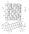
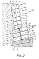
- Fig. 12 shows a retaining wall 20 with a variable effective cross section.
- a wall base 61 consists of several layers 43 of shaped stones 22 lying next to one another transversely to the longitudinal extension of the retaining wall 20, specifically in the embodiment according to FIG. Fig. 3, but with a third bearing surface 46 on the top, as in the embodiment of Fig. 2 or Figs. 8 and 9.
- the (smooth) backs 26 are within the Layers 43 facing each other. This results in the area of the wall base 61 or a lower foundation layer 62, a support width b 2 , which results from the support surfaces of the two adjacent form stones 22 of the foundation layer 62.
- the shaped stones 22 arranged one above the other are also in a reciprocal, form-fitting engagement by the projections 50 on the one hand and by the shoulder 53 arranged on the other hand.
- the arrangement is such that the shaped stones on the ground side are each reversed with respect to the top 23 and bottom 24. This results in a meandering interlocking of the stacked and adjacent stones in the area of a vertical central plane.
- Two adjacent shaped blocks of a layer 58 or 62 form a depression into which a projection 50 fits.
- an upper wall part 63 consists of layers 58, each with a shaped stone in the direction perpendicular to the level of the retaining wall 20.
- a statically favorable namely relatively wide core cross section 38 or 39 given.
- the lower molded block 22 of the upper wall part 63 is supported with the lower stop surface 34 on the upper stop surface 48 of the front molded block of the wall base 61. As a result, there is also a self-centering relative position of the shaped stones in this area.
- the number of layers 58 and 62 in the area of the wall base 61 is selected such that the lower core cross-section 39 is used on the basis of the specifications of the upper core cross-section 38 and the direction of the resultant R.
- the base layer 62 consists of three in the direction perpendicular to the plane of the retaining wall 20 other adjoining shaped stones 22.
- the design of the shaped stones in the sense of the exemplary embodiment in FIG. 2 and the relative arrangement thereof also create a self-centering support in the region of the transition from the upper wall part 63 to the wall base 61 and the layer 58 consisting of two shaped stones to the foundation layer 62 .
- this retaining wall 20 made of shaped stones of the preferred embodiment in FIG. 2, there is an optimal interlocking interlocking of shaped stones in the region of the respective cross-sectional widening of the retaining wall; thus in the area of the lower layer 58 to the upper layer 43 and from the lower layer 43 to the foundation layer 62.
- Two shaped stones of one layer (here layer 43) are replaced by an offset shaped stone of an adjacent layer (here: layer 58 on the one hand and foundation layer 62 on the other) covered, namely under the engagement of the paragraphs and depressions as a result of the cascade design.
- Such a wall is highly resilient or can be constructed with a large construction height.
- the shaped blocks can have any suitable or meaningful dimension.
- the total length of the shaped stone from the end face 25 to the rear face 26 is approximately 30 cm.
- the height of such a shaped block ie the distance between the support surfaces 27 and 31 from one another, is, for example, approximately 15 cm.
- the shoulders that is to say the distance between the parallel support surfaces, is 2.5 cm in one exemplary embodiment.
- the width of the small support surfaces 28, 32 .. is favorable with about 3.5 cm.
Landscapes
- Engineering & Computer Science (AREA)
- Environmental & Geological Engineering (AREA)
- Life Sciences & Earth Sciences (AREA)
- General Life Sciences & Earth Sciences (AREA)
- Mining & Mineral Resources (AREA)
- Paleontology (AREA)
- Civil Engineering (AREA)
- General Engineering & Computer Science (AREA)
- Structural Engineering (AREA)
- Retaining Walls (AREA)
- Materials For Medical Uses (AREA)
- Revetment (AREA)
Abstract
Description
- Die Erfindung betrifft einen Formstein aus Beton für die Herstellung einer gegenüber der Lotrechten gegen eine Erdreich-Hinterfüllung geneigten Stützmauer aus lagenweise übereinander angeordneten Formsteinen, die durch Vorsprünge und Vertiefungen an Ober- und Unterseite in formschlüssigem Eingriff miteinander sind. Weiterhin betrifft die Erfindung eine Stützmauer aus derartigen Formsteinen.
- Die vorliegende Erfindung bezweckt eine Weiterentwicklung und Verbesserung von Formsteinen der vorstehenden Ausführung sowie von daraus hergestellten Stützmauern in technischer und ästhetischer Hinsicht. Insbesondere sollen größere Konstruktionshöhen der Stützmauern bei gleicher Größe der Formsteine und gleichen technischen Voraussetzungen im übrigen ermöglicht werden.
- Zur Lösung dieser Aufgabe ist der erfindungsgemäße Formstein dadurch gekennzeichnet, daß Oberseite und Unterseite desselben je mindestens zwei stufenartig gegeneinander versetzte, parallel zueinander verlaufende Auflagerflächen aufweisen.
- Der so gebildete Versatz der Auflagerflächen an Oberseite und Unterseite ist so ausgebildet, daß die luftseitigen Auflagerflächen auf einem niedrigeren Niveau liegen als die erdseitigen Auflagerflächen. Die gegeneinander versetzten Auflagerflächen sind durch eine schräg gerichtete, nämlich in Richtung zur Luftseite abfallende Anschlagfläche miteinander verbunden.
- Durch diese Gestaltung der Formsteine wird überraschenderweise eine Vergrößerung der statisch wirksamen Auflagerfläche erzielt und bei geringfügigen Relativverschiebungen der Formsteine zueinander auch aufrechterhalten. Derartige geringfügige Relativverschiebungen sind beim Verbauen der Formsteine, also beim Aufsetzen der Stützmauer in der Praxis häufig nicht zu vermeiden.
- Da die Auflagerflächen bis unmittelbar an die Stirnseite sowie an die Rückseite der Formsteine verlaufen, ergibt sich eine statisch wirksame Auflagerbreite, die nur geringfügig kleiner ist als die Länge des Formsteins (Abmessung quer zur Längserstreckung der Stützwand). Die statische Achse eines Formsteins bzw. der daraus gebildeten Stützmauer verläuft durch die Mitte der Auflagerbreite. Erfindungsgemäß sind die Auflagerflächen der Formsteine unter einem schiefen Winkel zur statischen Achse angeordnet, wobei ein stumpfer Winkel auf der Erdseite und ein spitzer Winkel auf der Luftseite gegenüber der statischen Achse gebildet ist.
- Besonders vorteilhaft ist ein Formstein, bei dem auf der Oberseite - und korrespondierend an der Unterseite - drei oder mehr parallele Auflagerflächen gebildet sind, von denen die erdseitige in höherer Ebene sich erstreckt als die mittlere Auflagerfläche und diese wiederum in höherer Ebene als die luftseitige, wobei weiterhin die erdseitige und die luftseitige Auflagerfläche etwa gleich groß und die mittlere Auflagerfläche beträchtlich größer ist als die erdseitige und die luftseitige. Die drei (oder mehr) Auflagerflächen schließen demnach kaskadenförmig - von der Luftseite zur Erdseite ansteigend - aneinander an unter Anordnung schräggerichteter Anschlagflächen zwischen benachbarten Auflagerflächen.
- Mit einem Formstein der vorstehenden Ausführung ist eine Vielzahl von Gestaltungsmöglichkeiten der (Schwergewichts-) Stützmauern gegeben. Die Formsteine können lagenweise seitenverkehrt in bezug auf Erd- und Luftseite miteinander verbaut werden. Besonders vorteilhaft ist aber die Bildung von Stützmauern mit abgestufter Breite bzw. Tiefe durch Anordnung von zwei oder mehreren Formsteinen in Richtung quer zur Längserstreckung der Stützmauern nebeneinander. Es werden dadurch im Querschnitt stufenartig ausgebildete untere Mauersockel gebildet, die die Konstruktionshöhe bzw. die Belastbarkeit der Stützmauer beträchtlich erhöhen. Im Bereich des Übergangs von einer Abstufung der Stützmauer zur anderen liegen die in der Höhe benachbarten Formsteine versetzt zueinander und mit wechselseitigem formschlüssigem Eingriff miteinander (Verzahnung).
- Nach einem weiteren Merkmal der Erfindung sind die Formsteine erdseitig und luftseitig mit an einen durch die Auflagerflächen gebildeten Tragteil anschließenden Kopfteilen versehen, die zur Dekoration, zur besseren Schallabsorption oder zur Verzahnung mit dem Erdreich in entsprechender Weise (unterschiedlich) gestaltet sein können.
- Weitere Einzelheiten des erfindungsgemäßen Formsteins sowie der Stützmauer werden nachfolgend anhand der Zeichnungen näher erläutert. Es zeigen:
- Fig. 1 einen Formstein in Seitenansicht,
- Fig. 2 ein anderes, bevorzugtes Ausführungsbeispiel eines Formsteins, ebenfalls in Seitenansicht,
- Fig. 3 zwei Formsteine in der Ausführung gemäß Fig. 2 in lagegerechter Anordnung übereinander in Seitenansicht,
- Fig. 4 eine aus Formsteinen gemäß Fig. 2 und 3 gebildete Stützmauer im Vertikalschnitt,
- Fig. 5 eine Vorder- bzw. Längsansicht der Stützmauer gemäß Fig. 4,
- Fig. 6 ein weiteres Ausführungsbeispiel eines Formsteins in Seitenansicht,
- Fig. 7 zwei Formsteine einer weiteren Ausführungsform in lagegerechter Anordnung, in Seitenansicht,
- Fig. 8 ein weiteres Ausführungsbeispiel eines Formsteins in Seitenansicht,
- Fig. 9 eine universell einsetzbare Ausführungsform eines Formsteins in Seitenansicht,
- Fig. 10 einen Ausschnitt einer Stützmauer im Vertikalschnitt aus Formsteinen gemäß Fig. 2,
- Fig. 11 einen Abschnitt einer Stützmauer gemäß Fig. 10 in Vorderansicht,
- Fig. 12 eine stufenförmig ausgebildete Stützmauer in Seitenansicht bzw. im Vertikalschnitt,
- Fig. 13 ein anderes Ausführungsbeispiel einer stufenförmig ausgebildeten Stützmauer aus Formsteinen gemäß Fig. 2.
- Die in den Zeichnungen dargestellten Ausführungsbeispiele von Formsteinen dienen zur Herstellung von Stützmauern, nämlich Schwergewichts-Trocken-Stützmauern 20 mit einseitiger Erdreich-Hinterfüllung 21. Die Stützmauer 20 ist in einer gegen die Erdreich-Hinterfüllung geneigten Ebene angeordnet. Der Winkel der Stützmauer 20 gegenüber der Horizontalen beträgt vorzugsweise zwischen 60° und 70°.
- Die in den Zeichnungen dargestellten Ausführungsbeispiele von Formsteinen 22 bilden eine Oberseite 23, eine Unterseite 24, eine luftseitige Stirnseite 25 und eine der Erdreich-Hinterfüllung 21 zugekehrte Rückseite 26. Oberseite 23 und Unterseite 24 sind bei allen Ausführungsformen korrespondierend zueinander gestaltet, derart, daß ein passendes, formschlüssiges Übereinanderlegen der Formsteine 22 innerhalb der Stützmauer 20 gewährleistet ist.
- Zur Erzielung optimaler statischer Verhältnisse bestehen Oberseite 23 und Unterseite 24 aus mindestens zwei Auflagerflächen 27 und 28, die sich in der Höhe nach gegeneinander versetzten Ebenen erstrecken und stets parallel zueinander verlaufen. Die der Luftseite zugekehrte Auflagerfläche 28 ist gegenüber der erdseitigen Auflagerfläche 27 nach unten abgesetzt - bei horizontal liegendem Formstein - unter Bildung eines Absatzes 29 mit einer im vorliegenden Falle schrägen Anschlagfläche 30. Diese ist zur Luftseite hin abfallend angeordnet, beispielsweise mit einem Winkel von etwa 45° zu den beiden Auflagerflächen 27 und 28.
- Korrespondierend hierzu sind auch an der Unterseite 24 eine erdseitige Auflagerfläche 31 und eine luftseitige Auflagerfläche 32 gebildet, die ebenfalls parallel zueinander sowie parallel zu den oberen Auflagerflächen 27, 28 gerichtet sind. Für den formschlüssigen wechselseitigen Eingriff mit einem benachbarten unteren Formstein ist die luftseitige Auflagerfläche 32 in gleicher Weise unter Bildung eines Absatzes 33 nach unten versetzt, der durch eine schräge Anschlagfläche 34 gebildet ist.
- Durch die Absätze mit Anschlagflächen auf Oberseite 23 und Unterseite 24 entstehen passend zueinander ausgebildete Erhöhungen und Vertiefungen im Bereich der aufeinander liegenden Flächen der Formsteine 22, die formschlüssig und selbstzentrierend ineinandergreifen.
- Bei ordnungsgemäß übereinander verlegten Formsteinen 22 liegen die Auflagerflächen 27 und 28 sowie die Anschlagfläche 30 vollflächig an den zugeordneten Auflagerflächen 31, 32 bzw. der Anschlagfläche 34 des benachbarten Formsteins an. Dadurch kommt statisch eine Auflagerbreite b zur Wirkung, die der Summe der Auflager- und Anschlagflächen entspricht (s. z.B. Fig. 6). Die Auflagerbreite b ist für die Belastbarkeit bzw. zulässige Konstruktionshöhe der Stützmauer 20 maßgebend. Eine statische Achse 37 des Formsteins bzw. der Stützmauer erstreckt sich in der Mitte der Auflagerbreite b. Bei den gezeigten Ausführungsbeispielen sind die Formsteine 22 so ausgebildet, daß die statische Achse 37 unter einem schiefen Winkel zu den oberen und unteren Auflagerflächen 27 bzw. 31 gerichtet ist, und zwar derart, daß ein spitzer Winkel auf der Oberseite des Formsteins 22 der Luftseite zugekehrt ist. Die Stützmauer 20 ist vorzugsweise zur Erdreich-Hinterfüllung 21 in einem Winkelbereich von 60° bis 70° der statischen Achse 37 geneigt angeordnet. Daraus ergibt sich, daß die Auflagerflächen 27 und 28 sowie 31 und 32 stets zur Erdreich-Hinterfüllung 21 abfallend verlaufen, während die Anschlagflächen 30, 34 zur Luftseite hin ebenfalls abfallend sich erstrecken. Die vorgenannten Flächen haben dadurch eine selbstzentrierende Wirkung für die übereinander angeordneten Formsteine 22.
- Die Auflagerbreite b der Formsteine 22 bzw. der Stützmauer 20 insgesamt ist statisch von besonderer Bedeutung. Eine sich aus dem Eigengewicht der Stützmauer 20 sowie dem Erddruck aufgrund der Erdreich-Hinterfüllung 21 ergebende Kraft-Resultierende R muß aufgrund statischer Vorschriften innerhalb eines Kernquerschnitts 38 bzw. 39 der Stützmauer 20 verlaufen, und zwar jeweils im Bereich der unteren Formsteine 22. Dieser statisch relevante Kernquerschnitt 38, 39 beträgt 1/6 der Auflagerbreite b. Sie erstreckt sich mittig, also mit gleichen Abmessungen, zu beiden Seiten der statischen Achse 37. Eine große Auflagerbreite b hat einen entsprechend großen Kernquerschnitt 38 bzw. 39 zur Folge. Die Stützmauer 20 kann eine entsprechend größere Konstruktionshöhe aufweisen.
- Eine statisch interessante Größe ist weiterhin der Schwerpunkt S des Formsteins 22. Außerhalb der Aufstandsfläche der Formsteine 22, nämlich der Auflagerbreite b vorhandene Bereiche des Formsteins beeinflussen die Lage des Schwerpunkts S. Bei dem Ausführungsbeispiel der Fig. 1 wird an der Luftseite ein über die Auflagerbreite b hinwegragender Kopf 40 gebildet, der außen durch die Stirnseite 25 begrenzt wird. Das Gewicht bzw. die Masse dieses Kopfes 40 (in Fig. 1 schraffiert) bewirkt eine Verschiegung des Schwerpunktes S in Richtung zur Luftseite. In entgegengesetzter Richtung wirkt ein bei dem Ausführungsbeispiel der Fig. 1 im Querschnitt dreieckförmiger kleinerer Ansatz 41 im Bereich der Erdseite.
- Bei dem Ausführungsbeispiel der Fig. 6 ist der Ansatz 41 mit gleich großer Masse wie der Kopf 40 ausgebildet.
- Dadurch liegt der Schwerpunkt S exakt auf der statischen Achse 37. Darüber hinaus ist im Bereich der Rückseite 26 eine Stufe 42 eingeformt, die einerseits die Rauhigkeit des Formsteins erhöht und zum anderen als Griff zum Erfassen desselben dient.
- Die Formsteine 22 können an Oberseite 23 und Unterseite 24 mit mehr als zwei Auflagerflächen und Absätzen versehen sein. Bei dem Ausführungsbeispiel der Fig. 2 ist erdseitig eine weitere, dritte Auflagerfläche 46 gebildet, die nach dem Konstruktionsprinzip der Formsteine bei horizontaler Lage desselben auf höherer Ebene sich erstreckt als die benachbarte (größere) Auflagerfläche 27. Zwischen beiden wird ein Absatz 47 gebildet mit schräggerichteter Anschlagfläche 48. Auf der Erdseite schließt im vorliegenden Fall ein im Querschnitt trapezförmiger Ansatz 41 an, so daß die Auflagerfläche 46 Teil eines randseitigen, im Querschnitt trapezförmigen Vorsprungs 50 ist.
- Eine korrespondierende Auflagerfläche 51 mit Anschlagfläche 52 ist an der Unterseite gebildet, also ebenfalls mit einem Absatz 53. Oberseite und Unterseite sind auf diese Weise korrespondierend kaskadenförmig ausgebildet, auf der Oberseite 23 in Richtung zur Erdseite hin ansteigend. Die mittlere Auflagerfläche 27, 31 ist groß im Verhältnis zu den gleich großen Auflagerflächen 28 und 46 bzw. 32 und 51.
- Die Stirnseite 25 besteht bei diesem besonders vorteilhaften Formstein 22 aus einem im Querschnitt dreieckförmigem Kopf 40 mit unterer Rundkante 44. Die untere Ebene des Kopfes 40 erstreckt sich in Verlängerung der Auflagerfläche 32, ist jedoch nicht wirksamer Bestandteil derselben, da der Kopf 40 außerhalb der Auflagerbreite b liegt. Die Querschnittsflächen von Kopf 40 und Ansatz 41 sind gleich groß, so daß der Schwerpunkt S im Bereich der statischen Achse 37 liegt.
- Fig. 7 zeigt eine Variante, bei der ebenfalls drei Auflagerflächen 27, 28 und 46 an der Oberseite gebildet sind. Die letztgenannte Auflagerfläche 46 ist jedoch von größerer Länge als bei dem vorher beschriebenen Ausführungsbeispiel. Die größere Anzahl der Absätze 29, 33, 47, 53 an Oberseite 23 und Unterseite 24 bewirkt eine günstigere Verzahnung der Formsteine untereinander. Die glattflächige Rückseite 26 dieser Formsteine ist mit einer eingeformten Vertiefung 54 versehen, die als Griffvertiefung dienen kann.
- Fig. 8 zeigt einen Formstein 22 mit spiegelsymmetrischer Ausbildung derart, daß die Formsteine ohne Rücksicht auf Stirn- und Rückseite verlegt werden können, da beide Seiten übereinstimmend ausgebildet sind, im vorliegenden Falle bogenförmig, also ballig. Der Formstein ist mit jeweils drei Auflagerflächen 27, 28, 31, 32 sowie 46 und 51 an Oberseite und Unterseite versehen. Die der Erdreich-Hinterfüllung 21 zugekehrten Auflagerflächen 46 und 51 haben die gleiche Größe wie die luftseitigen Auflagerflächen 28 und 32. Auch die Höhe der Absätze 29, 33, 47, 53 ist übereinstimmend, so dßa eine seitenverdrehte Verlegung der Formsteine um 180° innerhalb der Stützmauer 20 möglich ist. Der Schwerpunkt S liegt bei dieser seitengleichen Ausbildung auf der statischen Achse 37.
- Die Anordnung von stets parallelen Auflagerflächen und, wie bei dem dargestellten Ausführungsbeispiel, von parallel zueinander angeordneten Anschlagflächen bewirkt, daß auch bei geringfügigen Relativverschiebungen der Formsteine zueinander, wie sie in der Praxis beim Errichten der Stützmauer nicht vollständig ausgeschlossen werden können, die wirksame Auflagerbreite b nicht in merkbarer Weise verändert wird. Wie in Fig. 3 in stark vergrößertem Maßstab dargestellt, entsteht lediglich im Bereich des Absatzes 29 bzw. 33 ein Spalt 55 von einem oder wenigen Millimetern. Die stabile, statisch einwandfreie Lagerung der Formsteine bleibt gleichwohl erhalten.
- Fig. 9 zeigt einen Formstein 22, der im Prinzip der Gestaltung gemäß Fig. 8 entspricht. Dies bedeutet, daß Kopf 40 und Ansatz 41 im wesentlichen übereinstimmend ausgebildet sind, so daß dieser Formstein seitenverkehrt einbaubar ist. Die Stirnseite und/oder die Rückseite - bei dem gezeigten Ausführungsbeispiel die Rückseite 26 - sind mit einer strukturierten Oberfläche versehen. Es handelt sich hier um in Längsrichtung bzw. horizontal verlaufende Nuten 64 von im wesentlichen trapezförmigem Querschnitt. Diese werden durch entsprechend gestaltete Rippen 65 voneinander getrennt.
- Aus einem so gestalteten Formstein 22 können Stützmauern unterschiedlicher äußerer Erscheinung gebildet werden, und zwar unter Verwendung nur eines Typs von Formsteinen (Fig. 9), und zwar durch abwechselndes Verlegen der Formsteine mit den strukturierten Flächen zur Luftseite bzw. zur Erdseite.
- Fig. 4 und 5 zeigen die Anordnung der Formsteine 22 in einer in üblicher Weise aufgebauten, bepflanzbaren Stützmauer 20 auf einem durchgehenden Betonfundament 56 mit keilförmigem Ausgleichsstück 57 zur Bestimmung der Neigung. Innerhalb einzelner Lagen 58 sind die Formsteine 22 mit Abstand voneinander und "auf Lücke" verlegt, so daß Zwischenräume 59 für eine Bepflanzung entstehen. Diese ermöglicht bei der vorliegenden Gestaltung der Formsteine die Heranführung des Erdreichs bis an die Stirnseite 25 der Formsteine 22 (Böschungswinkel 60 in Fig. 4).
- Fig. 12 zeigt eine Stützmauer 20 mit veränderlichem wirksamen Querschnitt. Im unteren Bereich besteht ein Mauersockel 61 aus mehreren Lagen 43 von quer zur Längserstrekkung der Stützmauer 20 nebeneinanderliegenden Formsteinen 22, und zwar in der Ausführung gem. Fig. 3, jedoch mit einer dritten Auflagerfläche 46 an der Oberseite, wie bei dem Ausführungsbeispiel der Fig. 2 bzw. der Fig. 8 und 9. Die (glatten) Rückseiten 26 sind innerhalb der Lagen 43 einander zugekehrt. Dadurch ergibt sich im Bereich des Mauersockels 61 bzw. einer unteren Fundamentlage 62 eine Auflagerbreite b2, die sich aus den Auflagerflächen der beiden jeweils nebeneinanderliegenden Formsteine 22 der Fundamentlage 62 ergibt. Die übereinander angeordneten Formsteine 22 stehen darüber hinaus in einem wechselseitigen, formschlüssigen Eingriff durch die Vorsprünge 50 einerseits und durch den gegenüberliegen angeordneten Absatz 53 andererseits. Die Anordnung ist so getroffen, daß die erdseitigen Formsteine jeweils seitenverkehrt in bezug auf Oberseite 23 und Unterseite 24 angeordnet sind. Dadurch ergibt sich im Bereich einer vertikalen Mittelebene eine mäanderförmige Verzahnung der übereinander sowie nebeneinanderliegenden Formsteine. Jeweils zwei benachbarte Formsteine einer Lage 58 bzw. 62 bilden ein Vertiefung, in die ein Vorsprung 50 passen eintritt.
- Oberhalb des Mauersockels 61 besteht ein Maueroberteil 63 aus Lagen 58 mit jeweils einem Formstein in der Richtung senkrecht zur Ebene der Stützmauer 20. Im Bereich der Fundamentlage 62 sowie des Übergangs von Maueroberteil 63 zum Mauersockel 61 ist ein statisch günstiger, nämlich verhältnismäßig breiter Kernquerschnitt 38 bzw. 39 gegeben.
- Der untere Formstein 22 des Maueroberteils 63 stützt sich mit der unteren Anschlagfläche 34 an der oberen Anschlagfläche 48 des vorderen Formsteins des Mauersockels 61 ab. Dadurch ist auch in diesem Bereich eine selbstzentrierende Relativlage der Formsteine gegeben. Die Anzahl der Lagen 58 bzw. 62 im Bereich des Mauersockels 61 ist so gewählt, daß der untere Kernquerschnitt 39 aufgrund der Vorgaben des oberen Kernquerschnitts 38 und der Richtung der Resultierenden R ausgenutzt wird.
- Die Stützmauer gemäß Fig. 13 ist ähnlich aufgebaut, nämlich mit Mauersockel 61 und Maueroberteil 63. Die Sockellage 62 besteht bei diesem Ausführungsbeispiel aus drei in Richtung senkrecht zur Ebene der Stützmauer 20 aneinander anschließenden Formsteinen 22. Durch die Gestaltung der Formsteine im Sinne des Ausführungsbeispiels der Fig. 2 und die Relativanordnung derselben wird auch hier eine selbstzentrierende Abstützung im Bereich des Übergangs von Maueroberteil 63 zu Mauersockel 61 sowie der aus zwei Formsteinen bestehenden Lage 58 zur Fundamentlage 62 geschaffen.
- Bei dieser Stützmauer 20 aus Formsteinen der bevorzugten Ausführung der Fig. 2 ist eine optimale formschlüssige Verzahnung von Formsteinen im Bereich der jeweiligen Querschnittsverbreiterung der Stützmauer gegeben; also im Bereich der unteren Lage 58 zur oberen Lage 43 und von der unteren Lage 43 zur Fundamentlage 62. Zwei Formsteine einer Lage (hier Lage 43) werden durch einen versetzt liegenden Formstein einer benachbarten Lage (hier: Lage 58 einerseits und Fundamentlage 62 andererseits) überdeckt, und zwar unter Eignriff der Absätze und Vertiefungen in Folge der kaskadenförmigen Gestaltung ineinander. Eine derartige Mauer ist hoch belastbar bzw. mit großer Konstruktionshöhe ausführbar.
- Die Formsteine können jede geeignete bzw. sinnvolle Abmessung aufweisen. Bei einer vorteilhaften Ausführung im Sinne von Fig. 1 und 2 beträgt die Gesamtlänge des Formsteins von der Stirnseite 25 zur Rückseite 26 etwa 30 cm. Die Höhe eines derartigen Formsteins, also der Abstand der Stützflächen 27 und 31 voneinander, beträgt beispielsweise ca. 15 cm. Die Absätze, also der Abstand der parallelen Auflagerflächen voneinander, beträgt bei einem Ausführungsbeispiel 2,5 cm. Die Breite der kleinen Auflagerflächen 28, 32.. ist mit etwa 3,5 cm günstig.
-
- 20 Stützmauer
- 21 Erdreich-Hinterfüllung
- 22 Formstein
- 23 Oberseite
- 24 Unterseite
- 25 Stirnseite
- 26 Rückseite
- 27 Auflagerfläche
- 28 Auflagerfläche
- 29 Absatz
- 30 Anschlagfläche
- 31 Auflagerfläche
- 32 Auflagerfläche
- 33 Absatz
- 34 Anschlagfläche
- 37 statische Achse
- 38 Kernquerschnitt
- 39 Kernquerschnitt
- 40 Kopf
- 41 Ansatz
- 42 Stufe
- 43 Lage
- 44 Rundkante
- 46 Auflagerfläche
- 47 Absatz
- 48 Anschlagfläche
- 50 Vorsprung
- 51 Auflagerfläche
- 52 Anschlagfläche
- 53 Absatz
- 54 Vertiefung
- 55 Spalt
- 56 Betonfundament
- 57 Ausgleichsstücke
- 58 Lage
- 59 Zwischenraum
- 60 Böschungswinkel
- 61 Mauersockel
- 62 Fundamentlage
- 63 Maueroberteil
- 64 Nut
- 65 Rippe
- R Resultierende
- S Schwerpunkt
- b,b j,b2 Auflagerbreite
- αWinkel
Claims (17)
Priority Applications (4)
| Application Number | Priority Date | Filing Date | Title |
|---|---|---|---|
| AT85114011T ATE54694T1 (de) | 1985-02-18 | 1985-11-04 | Stuetzmauer. |
| FI860273A FI85529C (fi) | 1985-02-18 | 1986-01-21 | Mot bakomliggande markfyllning lutad stoedmur. |
| AU52765/86A AU587599B2 (en) | 1985-02-18 | 1986-01-28 | Shaped (concrete) block for retaining walls and also a retaining wall |
| JP61028065A JPH0745732B2 (ja) | 1985-02-18 | 1986-02-13 | 擁壁用コンクリート成形ブロックならびに擁壁 |
Applications Claiming Priority (2)
| Application Number | Priority Date | Filing Date | Title |
|---|---|---|---|
| DE19853505530 DE3505530A1 (de) | 1985-02-18 | 1985-02-18 | (beton-) formstein fuer stuetzmauern sowie stuetzmauer |
| DE3505530 | 1985-02-18 |
Publications (2)
| Publication Number | Publication Date |
|---|---|
| EP0191908A1 true EP0191908A1 (de) | 1986-08-27 |
| EP0191908B1 EP0191908B1 (de) | 1990-07-18 |
Family
ID=6262821
Family Applications (1)
| Application Number | Title | Priority Date | Filing Date |
|---|---|---|---|
| EP85114011A Expired - Lifetime EP0191908B1 (de) | 1985-02-18 | 1985-11-04 | Stützmauer |
Country Status (7)
| Country | Link |
|---|---|
| US (1) | US4711606A (de) |
| EP (1) | EP0191908B1 (de) |
| CA (1) | CA1245870A (de) |
| DE (2) | DE3505530A1 (de) |
| DK (1) | DK518485A (de) |
| IT (1) | IT1188391B (de) |
| NO (1) | NO174752C (de) |
Cited By (4)
| Publication number | Priority date | Publication date | Assignee | Title |
|---|---|---|---|---|
| WO1996038636A1 (en) * | 1995-06-02 | 1996-12-05 | Produits Alba Inc. | A block for the mortarless construction of a wall |
| WO2001053612A1 (de) | 2000-01-20 | 2001-07-26 | Sf-Kooperation Gmbh Beton-Konzepte | Formstein aus beton, form und verfahren zur herstellung eines formsteins |
| WO2011111002A1 (en) * | 2010-03-09 | 2011-09-15 | Vieira Da Cunha Antonio Jose | Block for construction and method to build walls with said block |
| PL422755A1 (pl) * | 2017-09-05 | 2019-03-11 | Przedsiębiorstwo Realizacyjne Inora - Inorganic Activities Spółka Z Ograniczoną Odpowiedzialnością | Bloczek budowlany |
Families Citing this family (47)
| Publication number | Priority date | Publication date | Assignee | Title |
|---|---|---|---|---|
| CA1298982C (en) * | 1988-02-25 | 1992-04-21 | Eugene M. Bender | Retaining wall construction and blocks therefore |
| DE3810934A1 (de) * | 1988-03-31 | 1989-10-12 | Rudolf Peter Gmbh & Co Kg Kies | Verfahren zum verwerten von rueck-restbeton von transportbeton |
| US4993206A (en) * | 1989-02-03 | 1991-02-19 | National Concrete Masonry Association | Interlocking building units and walls constructed thereby |
| CA62573S (en) | 1989-02-20 | 1989-02-28 | Raymond Rodenburgh | Double unit for retaining wall |
| DE3917500A1 (de) * | 1989-05-30 | 1990-12-06 | Sf Vollverbundstein | (beton-) formstein fuer stuetzmauern, form fuer die herstellung sowie stuetzmauer |
| US5062610A (en) * | 1989-09-28 | 1991-11-05 | Block Systems Inc. | Composite masonry block mold for use in block molding machines |
| US5294216A (en) | 1989-09-28 | 1994-03-15 | Anchor Wall Systems, Inc. | Composite masonry block |
| US5017049A (en) * | 1990-03-15 | 1991-05-21 | Block Systems Inc. | Composite masonry block |
| US5044833A (en) * | 1990-04-11 | 1991-09-03 | Wilfiker William K | Reinforced soil retaining wall and connector therefor |
| US5120164A (en) * | 1991-05-24 | 1992-06-09 | Tony Iacocca | Retaining wall and block for constructing the same |
| USD344349S (en) | 1992-06-16 | 1994-02-15 | Masako Ohta | Wave energy dissipation block |
| US5704183A (en) | 1992-10-06 | 1998-01-06 | Anchor Wall Systems, Inc. | Composite masonry block |
| US5490363A (en) | 1992-10-06 | 1996-02-13 | Anchor Wall Sytems, Inc. | Composite masonry block |
| CA2146345C (en) | 1992-10-06 | 2001-01-09 | Dick J. Sievert | Composite masonry block |
| US5484236A (en) * | 1993-10-25 | 1996-01-16 | Allan Block Corporation | Method of forming concrete retaining wall block |
| US5425600A (en) * | 1994-01-21 | 1995-06-20 | Gordon; Bradford C. | Drainage block feedthrough for assembly of walls constructed of specialized retaining blocks |
| CA2143278A1 (en) * | 1994-04-14 | 1995-10-15 | Louis Arvai | Concrete gabions |
| US5913790A (en) * | 1995-06-07 | 1999-06-22 | Keystone Retaining Wall Systems, Inc. | Plantable retaining wall block |
| US5601384A (en) * | 1995-06-07 | 1997-02-11 | Keystone Retaining Wall Systems, Inc. | Plantable retaining wall |
| USD387434S (en) * | 1996-01-03 | 1997-12-09 | Keystone Retaining Wall Systems, Inc. | Front face of a plantable retaining wall block |
| US5765970A (en) * | 1996-06-17 | 1998-06-16 | Fox; James C. | Plastic retaining wall construction |
| US5879603A (en) | 1996-11-08 | 1999-03-09 | Anchor Wall Systems, Inc. | Process for producing masonry block with roughened surface |
| US6082057A (en) | 1996-11-08 | 2000-07-04 | Anchor Wall Systems, Inc. | Splitting technique |
| USD458693S1 (en) | 1996-11-08 | 2002-06-11 | Anchor Wall Systems, Inc. | Retaining wall block |
| US6029943A (en) | 1996-11-08 | 2000-02-29 | Anchor Wall Systems, Inc. | Splitting technique |
| USD415845S (en) * | 1997-02-11 | 1999-10-26 | Staten Bobby L | Decorative edging stone |
| USD409312S (en) * | 1997-02-11 | 1999-05-04 | Staten Bobby L | Decorative landscape stone |
| USD397451S (en) | 1997-06-10 | 1998-08-25 | Keystone Retaining Wall Systems, Inc. | Section of a retaining wall with plantable blocks |
| USD445512S1 (en) | 1997-10-27 | 2001-07-24 | Anchor Wall Systems, Inc. | Retaining wall block |
| USD430680S (en) * | 1999-01-15 | 2000-09-05 | Handy-Stone Corporation | Concrete block |
| DE29902467U1 (de) * | 1999-02-12 | 2000-06-29 | Karl Weber Betonwerk GmbH & Co. KG, 32457 Porta Westfalica | Palisade |
| WO2000047829A1 (en) * | 1999-02-12 | 2000-08-17 | Shaw Technologies, Inc. | Interlocking segmental retaining wall |
| DE19905842A1 (de) * | 1999-02-12 | 2000-08-17 | Karl Weber Betonwerk Gmbh & Co | Palisade |
| USD437422S1 (en) | 1999-08-17 | 2001-02-06 | Anchor Wall Systems, Inc. | Face of a retaining wall block |
| USD438640S1 (en) | 1999-08-17 | 2001-03-06 | Anchor Wall Systems, Inc. | Face of a retaining wall block |
| US6267533B1 (en) * | 1999-08-18 | 2001-07-31 | George S. Bourg | Erosion control system |
| US6250850B1 (en) | 1999-08-19 | 2001-06-26 | Rockwood Retaining Walls, Inc. | Block with multifaceted bottom surface |
| EP1493869A1 (de) * | 2003-06-30 | 2005-01-05 | Martin Mannhart | Elementblockmauer und Bauelement zum Erstellen einer solchen Mauer |
| DE102004024802A1 (de) | 2004-05-17 | 2005-12-08 | Sf-Kooperation Gmbh Beton-Konzepte | Stützmauer und Formstein aus Beton zur Herstellung einer Stützmauer |
| DE102004047823A1 (de) * | 2004-09-29 | 2006-03-30 | Sf-Kooperation Gmbh Beton-Konzepte | Mauer, insbesondere gegenüber der Lotrechten gegen eine Erdreich-Hinterfüllung geneigte Stützmauer |
| WO2006057986A1 (en) * | 2004-11-24 | 2006-06-01 | Contech Technologies, Inc. | Retaining wall block with face connection |
| DE102005050456A1 (de) | 2005-10-19 | 2007-04-26 | Sf-Kooperation Gmbh Beton-Konzepte | Stützwand |
| CA2679630A1 (en) * | 2007-02-12 | 2008-08-21 | Kingspan Research And Developments Limited | A composite panel |
| US7849656B2 (en) * | 2008-04-18 | 2010-12-14 | Anchor Wall Systems, Inc. | Dry cast block arrangement and methods |
| PT2319048E (pt) | 2008-08-22 | 2015-11-25 | Veritas Medical Solutions Llc | Bloco de alvenaria com superfícies continuamente curvadas |
| US9677271B2 (en) | 2015-10-08 | 2017-06-13 | Anchor Wall Systems, Inc. | Concrete unit and methods |
| US20190368152A1 (en) * | 2018-05-30 | 2019-12-05 | Earth Wall Products, Llc | Method for making modular retaining wall block with lever extension using cmu block machine |
Citations (3)
| Publication number | Priority date | Publication date | Assignee | Title |
|---|---|---|---|---|
| DE1912155A1 (de) * | 1969-03-11 | 1970-11-05 | Fischer Karl | Verbundstein |
| GB2000830A (en) * | 1977-07-11 | 1979-01-17 | Sf Vollverbundstein | Retaining wall of moulded concrete blocks and method for the production of the moulded concrete blocks |
| FR2544764A1 (fr) * | 1983-04-19 | 1984-10-26 | Rech Ste Civile Et | Element de soutenement pour la confection de talus de retenue et similaires |
Family Cites Families (16)
| Publication number | Priority date | Publication date | Assignee | Title |
|---|---|---|---|---|
| US789730A (en) * | 1903-01-30 | 1905-05-16 | Henry L Hinton | Tile building-block and method of forming same. |
| FR376718A (fr) * | 1907-04-12 | 1907-08-19 | Eugene Fichefet | Revetement de talus et de berges |
| CA744126A (en) * | 1961-11-13 | 1966-10-11 | R. Svee Hallbjorn | Block for making protecting covers on slopes of moles and breakwaters |
| US3488964A (en) * | 1967-11-27 | 1970-01-13 | Giken Kogyo Kk | Concrete block |
| JPS5056004A (de) * | 1973-09-14 | 1975-05-16 | ||
| DE7520030U (de) * | 1975-06-24 | 1977-06-16 | Sf-Vollverbundstein-Kooperation Gmbh, 2820 Bremen | Bauelementensatz zur erstellung von stuetzwaenden |
| EP0021449B1 (de) * | 1979-06-29 | 1984-06-27 | QUADIE-Bausysteme GmbH | Bauwerk in der Art einer Stützwand od. dgl. |
| DE8012113U1 (de) * | 1980-05-03 | 1980-07-31 | Gimmler, Helmut, 6618 Wadern-Bardenbach | Boeschungsformstein |
| DE3017064C2 (de) * | 1980-05-03 | 1984-04-05 | Gimmler, Luise Maria, 6618 Wadern-Bardenbach | Böschungsformstein |
| ATE7523T1 (de) * | 1981-03-10 | 1984-06-15 | Rolf Scheiwiller | Bausatz zur erstellung von mauern. |
| US4512685A (en) * | 1981-09-08 | 1985-04-23 | Ameron, Inc. | Mortarless retaining-wall system and components thereof |
| CA1182295A (en) * | 1982-08-16 | 1985-02-12 | Angelo Risi | Retaining wall system |
| AT391507B (de) * | 1983-01-24 | 1990-10-25 | Rausch Peter | Baustein |
| US4601148A (en) * | 1983-06-24 | 1986-07-22 | Angelo Risi | Module for walls and free standing structure |
| CH663437A5 (en) * | 1984-06-21 | 1987-12-15 | Carl Schiffer | Slope block |
| GB8428191D0 (en) * | 1984-11-08 | 1984-12-19 | Crighton J W | Building blocks |
-
1985
- 1985-02-18 DE DE19853505530 patent/DE3505530A1/de not_active Withdrawn
- 1985-11-04 DE DE8585114011T patent/DE3578765D1/de not_active Expired - Fee Related
- 1985-11-04 EP EP85114011A patent/EP0191908B1/de not_active Expired - Lifetime
- 1985-11-11 DK DK518485A patent/DK518485A/da not_active Application Discontinuation
- 1985-11-11 NO NO854476A patent/NO174752C/no not_active IP Right Cessation
-
1986
- 1986-01-24 CA CA000500289A patent/CA1245870A/en not_active Expired
- 1986-01-31 US US06/824,804 patent/US4711606A/en not_active Expired - Lifetime
- 1986-02-14 IT IT19422/86A patent/IT1188391B/it active
Patent Citations (3)
| Publication number | Priority date | Publication date | Assignee | Title |
|---|---|---|---|---|
| DE1912155A1 (de) * | 1969-03-11 | 1970-11-05 | Fischer Karl | Verbundstein |
| GB2000830A (en) * | 1977-07-11 | 1979-01-17 | Sf Vollverbundstein | Retaining wall of moulded concrete blocks and method for the production of the moulded concrete blocks |
| FR2544764A1 (fr) * | 1983-04-19 | 1984-10-26 | Rech Ste Civile Et | Element de soutenement pour la confection de talus de retenue et similaires |
Cited By (7)
| Publication number | Priority date | Publication date | Assignee | Title |
|---|---|---|---|---|
| WO1996038636A1 (en) * | 1995-06-02 | 1996-12-05 | Produits Alba Inc. | A block for the mortarless construction of a wall |
| US6108995A (en) * | 1995-06-02 | 2000-08-29 | Produits Alba, Inc. | Block for the mortarless construction of a wall |
| WO2001053612A1 (de) | 2000-01-20 | 2001-07-26 | Sf-Kooperation Gmbh Beton-Konzepte | Formstein aus beton, form und verfahren zur herstellung eines formsteins |
| DE10002390A1 (de) * | 2000-01-20 | 2001-07-26 | Sf Koop Gmbh Beton Konzepte | Formstein aus Beton, Form und Verfahren zur Herstellung eines Formsteins |
| WO2011111002A1 (en) * | 2010-03-09 | 2011-09-15 | Vieira Da Cunha Antonio Jose | Block for construction and method to build walls with said block |
| US9267282B2 (en) | 2010-03-09 | 2016-02-23 | António José Vieira Da Cunha | Block for construction and method to build walls with said block |
| PL422755A1 (pl) * | 2017-09-05 | 2019-03-11 | Przedsiębiorstwo Realizacyjne Inora - Inorganic Activities Spółka Z Ograniczoną Odpowiedzialnością | Bloczek budowlany |
Also Published As
| Publication number | Publication date |
|---|---|
| IT1188391B (it) | 1988-01-07 |
| NO174752B (no) | 1994-03-21 |
| NO854476L (no) | 1986-08-19 |
| DK518485A (da) | 1986-08-19 |
| NO174752C (no) | 1994-06-29 |
| DE3578765D1 (de) | 1990-08-23 |
| CA1245870A (en) | 1988-12-06 |
| DE3505530A1 (de) | 1986-08-21 |
| IT8619422A0 (it) | 1986-02-14 |
| US4711606A (en) | 1987-12-08 |
| EP0191908B1 (de) | 1990-07-18 |
| IT8619422A1 (it) | 1987-08-14 |
| DK518485D0 (da) | 1985-11-11 |
Similar Documents
| Publication | Publication Date | Title |
|---|---|---|
| EP0191908A1 (de) | Stützmauer | |
| AT391507B (de) | Baustein | |
| EP0170113A1 (de) | Baustein | |
| EP0058925A1 (de) | Bauteilsatz für eine als Gitterwand ausgebildete Stützmauer, Lärmschutzwand oder dergleichen | |
| DE1213462B (de) | Kunstformstein, insbesondere Betonformstein | |
| EP0517117B1 (de) | Pflanzkasten aus Holz | |
| DE69100069T2 (de) | Kunststofffliese zur Bekleidung von Gebäudeterrassen. | |
| EP0016727B1 (de) | Bausatz aus Verbundsteinen, insbesondere für die Hangsicherung und Flussbettverbauung | |
| DE8816509U1 (de) | Rasenpflasterstein | |
| DE9302191U1 (de) | Pflasterstein in polygoner, insbesondere rechteckiger Form | |
| DE8504505U1 (de) | Formstein aus Beton | |
| DE3510914A1 (de) | Doppelstein | |
| DE2908578C2 (de) | Rahmenförmiges Fertigteil aus Beton für eine Raumgitterwand als Stützwand od.dgl. | |
| EP1897995A1 (de) | Bausatz zur Begrenzung von Beeten, Grünflächen, Wegen oder sonstigen Flächen mittels Begrenzungssteinen | |
| DE2947653A1 (de) | Betonblock zur herstellung von stuetzmauern und sichtwaenden | |
| EP1954882B1 (de) | Formstein | |
| DE3837243A1 (de) | Formstein fuer eine bepflanzbare boeschungssicherung | |
| EP2331752A1 (de) | Erdreichabdeckung aus formsteinen | |
| DE3409884C2 (de) | ||
| EP0952260B1 (de) | Beton-Formstein-System | |
| DE2430489C2 (de) | Plattenverband aus im Grundriß rechteckförmigen, an einer Stoßstelle geneigt zueinander angeordneten Betonkammerplatten, insbesondere zur Sohlen- und Uferbefestigung von Gewässern | |
| DE29619957U1 (de) | Pflasterelement zum Aufbau eines offenen, zusammenhängenden Bodenbelags | |
| EP1835077A1 (de) | Stein zur Errichtung von Schwergewichtsmauern | |
| DE3517337A1 (de) | Formsteine fuer eine treppenartige boeschungswand sowie verfahren zum herstellen einer solchen boeschungswand | |
| DE8914892U1 (de) | Formstein-Bauelement |
Legal Events
| Date | Code | Title | Description |
|---|---|---|---|
| PUAI | Public reference made under article 153(3) epc to a published international application that has entered the european phase |
Free format text: ORIGINAL CODE: 0009012 |
|
| AK | Designated contracting states |
Kind code of ref document: A1 Designated state(s): AT BE CH DE FR GB IT LI NL SE |
|
| 17P | Request for examination filed |
Effective date: 19870203 |
|
| 17Q | First examination report despatched |
Effective date: 19880316 |
|
| 17Q | First examination report despatched |
Effective date: 19881118 |
|
| GRAA | (expected) grant |
Free format text: ORIGINAL CODE: 0009210 |
|
| AK | Designated contracting states |
Kind code of ref document: B1 Designated state(s): AT BE CH DE FR GB IT LI NL SE |
|
| REF | Corresponds to: |
Ref document number: 54694 Country of ref document: AT Date of ref document: 19900815 Kind code of ref document: T |
|
| GBT | Gb: translation of ep patent filed (gb section 77(6)(a)/1977) | ||
| REF | Corresponds to: |
Ref document number: 3578765 Country of ref document: DE Date of ref document: 19900823 |
|
| ITF | It: translation for a ep patent filed | ||
| ET | Fr: translation filed | ||
| PLBE | No opposition filed within time limit |
Free format text: ORIGINAL CODE: 0009261 |
|
| STAA | Information on the status of an ep patent application or granted ep patent |
Free format text: STATUS: NO OPPOSITION FILED WITHIN TIME LIMIT |
|
| 26N | No opposition filed | ||
| ITTA | It: last paid annual fee | ||
| PGFP | Annual fee paid to national office [announced via postgrant information from national office to epo] |
Ref country code: NL Payment date: 19941130 Year of fee payment: 10 |
|
| PGFP | Annual fee paid to national office [announced via postgrant information from national office to epo] |
Ref country code: BE Payment date: 19950104 Year of fee payment: 10 |
|
| EAL | Se: european patent in force in sweden |
Ref document number: 85114011.1 |
|
| PG25 | Lapsed in a contracting state [announced via postgrant information from national office to epo] |
Ref country code: BE Effective date: 19951130 |
|
| BERE | Be: lapsed |
Owner name: SF-VOLLVERBUNDSTEIN-KOOPERATION G.M.B.H. Effective date: 19951130 |
|
| PG25 | Lapsed in a contracting state [announced via postgrant information from national office to epo] |
Ref country code: NL Effective date: 19960601 |
|
| NLV4 | Nl: lapsed or anulled due to non-payment of the annual fee |
Effective date: 19960601 |
|
| PGFP | Annual fee paid to national office [announced via postgrant information from national office to epo] |
Ref country code: SE Payment date: 20001106 Year of fee payment: 16 |
|
| PGFP | Annual fee paid to national office [announced via postgrant information from national office to epo] |
Ref country code: FR Payment date: 20001110 Year of fee payment: 16 |
|
| PG25 | Lapsed in a contracting state [announced via postgrant information from national office to epo] |
Ref country code: SE Free format text: LAPSE BECAUSE OF NON-PAYMENT OF DUE FEES Effective date: 20011105 |
|
| REG | Reference to a national code |
Ref country code: GB Ref legal event code: IF02 |
|
| EUG | Se: european patent has lapsed |
Ref document number: 85114011.1 |
|
| PG25 | Lapsed in a contracting state [announced via postgrant information from national office to epo] |
Ref country code: FR Free format text: LAPSE BECAUSE OF NON-PAYMENT OF DUE FEES Effective date: 20020730 |
|
| REG | Reference to a national code |
Ref country code: FR Ref legal event code: ST |
|
| REG | Reference to a national code |
Ref country code: FR Ref legal event code: ST |
|
| PGFP | Annual fee paid to national office [announced via postgrant information from national office to epo] |
Ref country code: DE Payment date: 20021113 Year of fee payment: 18 Ref country code: AT Payment date: 20021113 Year of fee payment: 18 |
|
| PG25 | Lapsed in a contracting state [announced via postgrant information from national office to epo] |
Ref country code: AT Free format text: LAPSE BECAUSE OF NON-PAYMENT OF DUE FEES Effective date: 20031104 |
|
| PG25 | Lapsed in a contracting state [announced via postgrant information from national office to epo] |
Ref country code: DE Free format text: LAPSE BECAUSE OF NON-PAYMENT OF DUE FEES Effective date: 20040602 |
|
| PGFP | Annual fee paid to national office [announced via postgrant information from national office to epo] |
Ref country code: GB Payment date: 20041104 Year of fee payment: 20 |
|
| PGFP | Annual fee paid to national office [announced via postgrant information from national office to epo] |
Ref country code: CH Payment date: 20041117 Year of fee payment: 20 |
|
| PG25 | Lapsed in a contracting state [announced via postgrant information from national office to epo] |
Ref country code: GB Free format text: LAPSE BECAUSE OF EXPIRATION OF PROTECTION Effective date: 20051103 |
|
| REG | Reference to a national code |
Ref country code: GB Ref legal event code: PE20 |
|
| REG | Reference to a national code |
Ref country code: CH Ref legal event code: PL |