EP0191908A1 - Mur de soutènement - Google Patents
Mur de soutènement Download PDFInfo
- Publication number
- EP0191908A1 EP0191908A1 EP85114011A EP85114011A EP0191908A1 EP 0191908 A1 EP0191908 A1 EP 0191908A1 EP 85114011 A EP85114011 A EP 85114011A EP 85114011 A EP85114011 A EP 85114011A EP 0191908 A1 EP0191908 A1 EP 0191908A1
- Authority
- EP
- European Patent Office
- Prior art keywords
- shaped
- retaining wall
- support
- stones
- bearing surface
- Prior art date
- Legal status (The legal status is an assumption and is not a legal conclusion. Google has not performed a legal analysis and makes no representation as to the accuracy of the status listed.)
- Granted
Links
- 239000004575 stone Substances 0.000 claims abstract description 50
- 239000002689 soil Substances 0.000 claims description 10
- 238000004519 manufacturing process Methods 0.000 claims description 3
- 230000015572 biosynthetic process Effects 0.000 claims description 2
- 239000011449 brick Substances 0.000 claims 1
- 230000000284 resting effect Effects 0.000 abstract 1
- 230000003068 static effect Effects 0.000 description 14
- 230000005484 gravity Effects 0.000 description 6
- 238000010276 construction Methods 0.000 description 4
- 238000006073 displacement reaction Methods 0.000 description 3
- 230000000694 effects Effects 0.000 description 3
- 230000007704 transition Effects 0.000 description 3
- 230000001154 acute effect Effects 0.000 description 2
- 230000002349 favourable effect Effects 0.000 description 2
- 230000000630 rising effect Effects 0.000 description 2
- 238000010521 absorption reaction Methods 0.000 description 1
- 238000005034 decoration Methods 0.000 description 1
Images


Classifications
-
- E—FIXED CONSTRUCTIONS
- E02—HYDRAULIC ENGINEERING; FOUNDATIONS; SOIL SHIFTING
- E02D—FOUNDATIONS; EXCAVATIONS; EMBANKMENTS; UNDERGROUND OR UNDERWATER STRUCTURES
- E02D29/00—Independent underground or underwater structures; Retaining walls
- E02D29/02—Retaining or protecting walls
- E02D29/025—Retaining or protecting walls made up of similar modular elements stacked without mortar
Definitions
- the invention relates to a shaped block made of concrete for the production of a retaining wall inclined with respect to the vertical against a soil backfill from layered shaped blocks which are in positive engagement with one another by means of projections and depressions on the top and bottom. Furthermore, the invention relates to a retaining wall made of such shaped stones.
- the present invention aims to further develop and improve molded blocks of the above design and retaining walls made therefrom in technical and aesthetic terms.
- larger structural heights of the retaining walls are to be made possible with the same size of the shaped blocks and the same technical requirements.
- the shaped block according to the invention is characterized in that the top and bottom of the same each have at least two staggered, mutually parallel support surfaces.
- the offset of the bearing surfaces on the top and bottom sides is formed in such a way that the air-side bearing surfaces are at a lower level than the earth-side bearing surfaces.
- the mutually offset bearing surfaces are connected to one another by an obliquely directed stop surface that drops towards the air side.
- This configuration of the shaped stones surprisingly achieves an enlargement of the statically effective support surface and also maintains them with slight relative displacements of the shaped stones with respect to one another. Such slight relative displacements are often unavoidable in practice when installing the shaped blocks, i.e. when the retaining wall is put on.
- the resulting statically effective support width is only slightly smaller than the length of the molded block (dimension transverse to the longitudinal extension of the supporting wall).
- the static axis of a shaped stone or the retaining wall formed from it runs through the center of the support width.
- the support surfaces of the shaped stones are arranged at an oblique angle to the static axis, an obtuse angle being formed on the earth side and an acute angle on the air side relative to the static axis.
- a molded block is particularly advantageous in which three or more parallel bearing surfaces are formed on the upper side - and correspondingly on the lower side - by which the earth-side extends in a higher plane than the middle bearing surface and this in turn in a higher plane than the air-side, the earth-side and the air-side bearing surface being approximately the same size and the mean bearing surface being considerably larger than the earth-side and the air-side.
- the three (or more) support surfaces are thus cascaded - rising from the air side to the earth side - with one another with angled stop surfaces between adjacent support surfaces.
- the shaped blocks can be installed side-by-side with respect to the earth and air side.
- the formation of retaining walls with a graduated width or depth by arranging two or more shaped blocks in the direction transverse to the longitudinal extent of the retaining walls next to one another is particularly advantageous.
- lower wall bases are formed, which have a step-like cross section, which considerably increase the construction height and the load-bearing capacity of the retaining wall.
- the form stones that are adjacent in height are offset from one another and with mutual positive engagement with one another (toothing).
- the shaped blocks are provided on the earth side and on the air side with head parts which adjoin a support part formed by the support surfaces and which can be designed in a corresponding (different) manner for decoration, for better sound absorption or for interlocking with the ground.
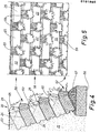
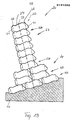
- the exemplary embodiments of shaped blocks shown in the drawings are used for the production of retaining walls, namely heavyweight dry retaining walls 20 with one-sided soil backfill 21.
- the retaining wall 20 is arranged in a plane inclined against the soil backfill.
- the angle of the retaining wall 20 with respect to the horizontal is preferably between 60 ° and 70 °.
- the exemplary embodiments of shaped stones 22 shown in the drawings form an upper side 23, an underside 24, an air-side end face 25 and a rear side 26 facing the soil backfill 21.
- the upper side 23 and underside 24 are designed to correspond to one another in all embodiments, in such a way that a appropriate, form-fitting superimposition of the shaped blocks 22 is ensured within the retaining wall 20.
- the top 23 and bottom 24 consist of at least two support surfaces 27 and 28, which extend in mutually offset planes and always run parallel to one another.
- the support surface 28 facing the air side is offset from the ground-side support surface 27 downward - with horizontally lying molded block - to form a shoulder 29 with an oblique stop surface 30 in the present case. This is arranged sloping towards the air side, for example at an angle of approximately 45 ° to the two support surfaces 27 and 28.
- an earth-side bearing surface 31 and an air-side bearing surface 32 are also formed on the underside 24, which are also directed parallel to one another and parallel to the upper bearing surfaces 27, 28.
- the air-side bearing surface 32 is offset downwards in the same way, forming a shoulder 33, which is formed by an oblique stop surface 34.
- the shoulders with abutment surfaces on the top 23 and underside 24 give rise to depressions and recesses in the area of the superimposed surfaces of the shaped blocks 22, which interlock in a form-fitting and self-centering manner.
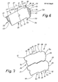
- a support width b statically comes into effect, which corresponds to the sum of the support and stop surfaces (see, for example, FIG. 6).
- the support width b is decisive for the load capacity or permissible construction height of the retaining wall 20.
- a static axis 37 of the shaped block or the retaining wall extends in the middle of the support width b.
- the shaped blocks 22 are designed such that the static axis 37 is directed at an oblique angle to the upper and lower bearing surfaces 27 and 31, respectively, in such a way that an acute angle on the upper side of the shaped block 22 faces the air side is.
- the retaining wall 20 is preferably arranged inclined to the soil backfill 21 in an angular range of 60 ° to 70 ° of the static axis 37. The result of this is that the bearing surfaces 27 and 28 and 31 and 32 always slope towards the backfill 21, while the stop surfaces 30, 34 also extend towards the air side. As a result, the aforementioned surfaces have a self-centering effect for the shaped stones 22 arranged one above the other.
- the support width b of the shaped blocks 22 or the retaining wall 20 as a whole is of particular importance statically.
- a force resultant R resulting from the dead weight of the retaining wall 20 and the earth pressure due to the soil backfilling 21 must run due to static regulations within a core cross section 38 or 39 of the retaining wall 20, in each case in the area of the lower shaped stones 22.
- This is static relevant core cross section 38, 39 is 1/6 of the support width b. It extends in the middle, ie with the same dimensions, on both sides of the static axis 37.
- a large support width b results in a correspondingly large core cross section 38 or 39.
- the retaining wall 20 can have a correspondingly larger construction height.
- a statically interesting quantity is also the center of gravity S of the shaped block 22.
- the width of the support is shown on the air side b protruding head 40 is formed, which is limited on the outside by the end face 25.
- the weight or the mass of this head 40 (hatched in FIG. 1) causes the center of gravity S to shift towards the air side.
- a smaller extension 41 which is triangular in cross section in the embodiment of FIG. 1, acts in the region of the earth side.
- the projection 41 is of the same size as the head 40.
- a step 42 is formed in the area of the rear side 26, which increases the roughness of the shaped block on the one hand and serves as a handle for grasping the same on the other.
- the shaped stones 22 can be provided on the top 23 and bottom 24 with more than two bearing surfaces and shoulders.
- a further, third support surface 46 is formed on the ground side, which extends according to the design principle of the shaped blocks in a horizontal position of the same at a higher level than the adjacent (larger) support surface 27.
- a shoulder 47 is formed with an oblique direction Stop surface 48.
- a shoulder 41 with a trapezoidal cross section adjoins the earth side, so that the bearing surface 46 is part of an edge-side projection 50 with a trapezoidal cross section.
- a corresponding support surface 51 with stop surface 52 is formed on the underside, that is to say also with a shoulder 53.
- the top and bottom are correspondingly cascaded, rising on the top 23 toward the earth side.
- the middle bearing surface 27, 31 is large in relation to the bearing surfaces 28 and 46 or 32 and 51 of the same size.
- the end face 25 consists of a head 40 with a triangular cross section with a lower round edge 44.
- the lower plane of the head 40 extends in extension of the support surface 32, but is not an effective component of the same, since the head 40 is outside the support width b lies.
- the cross-sectional areas of head 40 and shoulder 41 are of equal size, so that the center of gravity S lies in the area of the static axis 37.
- Fig. 7 shows a variant in which three support surfaces 27, 28 and 46 are also formed on the top.
- the latter bearing surface 46 is of greater length than in the previously described embodiment.
- the greater number of paragraphs 29, 33, 47, 53 on the top 23 and bottom 24 causes the molded blocks to be more closely interlinked.
- the smooth-surface back 26 of these shaped stones is provided with a molded-in depression 54, which can serve as a recess in the handle.
- Fig. 8 shows a shaped block 22 with mirror-symmetrical design such that the shaped blocks can be laid regardless of the front and back, since both sides are designed to match, in the present case arcuate, that is, spherical.
- the shaped block is provided with three bearing surfaces 27, 28, 31, 32 and 46 and 51 on the top and bottom.
- the bearing surfaces 46 and 51 facing the soil backfill 21 have the same size as the air-side bearing surfaces 28 and 32.
- the heels 29, 33, 47, 53 are also the same, so that a twisted laying of the shaped blocks by 180 ° within the Retaining wall 20 is possible.
- the center of gravity S lies on the static axis 37 in this same-sided design.
- FIG. 9 shows a shaped block 22 which corresponds in principle to the design according to FIG. 8. This means that the head 40 and shoulder 41 are formed essentially in agreement, so that this molded block can be installed reversed.
- the front side and / or the rear side - in the exemplary embodiment shown the rear side 26 - are provided with a structured surface. These are grooves 64 which run in the longitudinal direction or horizontally and have an essentially trapezoidal cross section. These are separated from one another by appropriately designed ribs 65.
- Retaining walls of different external appearance can be formed from a shaped block 22 designed in this way, using only one type of shaped blocks (FIG. 9), and in fact by alternately laying the shaped blocks with the structured surfaces on the air side or on the earth side.
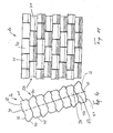
- FIG. 4 and 5 show the arrangement of the shaped stones 22 in a customarily constructed, plantable retaining wall 20 on a continuous concrete foundation 56 with a wedge-shaped compensating piece 57 for determining the inclination.
- the shaped blocks 22 are spaced from one another and “on a gap”, so that gaps 59 are created for planting. In the present design of the shaped blocks, this enables the soil to be brought up to the end face 25 of the shaped blocks 22 (slope angle 60 in FIG. 4).
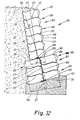
- Fig. 12 shows a retaining wall 20 with a variable effective cross section.
- a wall base 61 consists of several layers 43 of shaped stones 22 lying next to one another transversely to the longitudinal extension of the retaining wall 20, specifically in the embodiment according to FIG. Fig. 3, but with a third bearing surface 46 on the top, as in the embodiment of Fig. 2 or Figs. 8 and 9.
- the (smooth) backs 26 are within the Layers 43 facing each other. This results in the area of the wall base 61 or a lower foundation layer 62, a support width b 2 , which results from the support surfaces of the two adjacent form stones 22 of the foundation layer 62.
- the shaped stones 22 arranged one above the other are also in a reciprocal, form-fitting engagement by the projections 50 on the one hand and by the shoulder 53 arranged on the other hand.
- the arrangement is such that the shaped stones on the ground side are each reversed with respect to the top 23 and bottom 24. This results in a meandering interlocking of the stacked and adjacent stones in the area of a vertical central plane.
- Two adjacent shaped blocks of a layer 58 or 62 form a depression into which a projection 50 fits.
- an upper wall part 63 consists of layers 58, each with a shaped stone in the direction perpendicular to the level of the retaining wall 20.
- a statically favorable namely relatively wide core cross section 38 or 39 given.
- the lower molded block 22 of the upper wall part 63 is supported with the lower stop surface 34 on the upper stop surface 48 of the front molded block of the wall base 61. As a result, there is also a self-centering relative position of the shaped stones in this area.
- the number of layers 58 and 62 in the area of the wall base 61 is selected such that the lower core cross-section 39 is used on the basis of the specifications of the upper core cross-section 38 and the direction of the resultant R.
- the base layer 62 consists of three in the direction perpendicular to the plane of the retaining wall 20 other adjoining shaped stones 22.
- the design of the shaped stones in the sense of the exemplary embodiment in FIG. 2 and the relative arrangement thereof also create a self-centering support in the region of the transition from the upper wall part 63 to the wall base 61 and the layer 58 consisting of two shaped stones to the foundation layer 62 .
- this retaining wall 20 made of shaped stones of the preferred embodiment in FIG. 2, there is an optimal interlocking interlocking of shaped stones in the region of the respective cross-sectional widening of the retaining wall; thus in the area of the lower layer 58 to the upper layer 43 and from the lower layer 43 to the foundation layer 62.
- Two shaped stones of one layer (here layer 43) are replaced by an offset shaped stone of an adjacent layer (here: layer 58 on the one hand and foundation layer 62 on the other) covered, namely under the engagement of the paragraphs and depressions as a result of the cascade design.
- Such a wall is highly resilient or can be constructed with a large construction height.
- the shaped blocks can have any suitable or meaningful dimension.
- the total length of the shaped stone from the end face 25 to the rear face 26 is approximately 30 cm.
- the height of such a shaped block ie the distance between the support surfaces 27 and 31 from one another, is, for example, approximately 15 cm.
- the shoulders that is to say the distance between the parallel support surfaces, is 2.5 cm in one exemplary embodiment.
- the width of the small support surfaces 28, 32 .. is favorable with about 3.5 cm.
Landscapes
- Engineering & Computer Science (AREA)
- Environmental & Geological Engineering (AREA)
- Life Sciences & Earth Sciences (AREA)
- General Life Sciences & Earth Sciences (AREA)
- Mining & Mineral Resources (AREA)
- Paleontology (AREA)
- Civil Engineering (AREA)
- General Engineering & Computer Science (AREA)
- Structural Engineering (AREA)
- Retaining Walls (AREA)
- Materials For Medical Uses (AREA)
- Revetment (AREA)
Priority Applications (4)
| Application Number | Priority Date | Filing Date | Title |
|---|---|---|---|
| AT85114011T ATE54694T1 (de) | 1985-02-18 | 1985-11-04 | Stuetzmauer. |
| FI860273A FI85529C (fi) | 1985-02-18 | 1986-01-21 | Mot bakomliggande markfyllning lutad stoedmur. |
| AU52765/86A AU587599B2 (en) | 1985-02-18 | 1986-01-28 | Shaped (concrete) block for retaining walls and also a retaining wall |
| JP61028065A JPH0745732B2 (ja) | 1985-02-18 | 1986-02-13 | 擁壁用コンクリート成形ブロックならびに擁壁 |
Applications Claiming Priority (2)
| Application Number | Priority Date | Filing Date | Title |
|---|---|---|---|
| DE19853505530 DE3505530A1 (de) | 1985-02-18 | 1985-02-18 | (beton-) formstein fuer stuetzmauern sowie stuetzmauer |
| DE3505530 | 1985-02-18 |
Publications (2)
| Publication Number | Publication Date |
|---|---|
| EP0191908A1 true EP0191908A1 (fr) | 1986-08-27 |
| EP0191908B1 EP0191908B1 (fr) | 1990-07-18 |
Family
ID=6262821
Family Applications (1)
| Application Number | Title | Priority Date | Filing Date |
|---|---|---|---|
| EP85114011A Expired - Lifetime EP0191908B1 (fr) | 1985-02-18 | 1985-11-04 | Mur de soutènement |
Country Status (7)
| Country | Link |
|---|---|
| US (1) | US4711606A (fr) |
| EP (1) | EP0191908B1 (fr) |
| CA (1) | CA1245870A (fr) |
| DE (2) | DE3505530A1 (fr) |
| DK (1) | DK518485A (fr) |
| IT (1) | IT1188391B (fr) |
| NO (1) | NO174752C (fr) |
Cited By (4)
| Publication number | Priority date | Publication date | Assignee | Title |
|---|---|---|---|---|
| WO1996038636A1 (fr) * | 1995-06-02 | 1996-12-05 | Produits Alba Inc. | Bloc pour la construction d'un mur sans mortier |
| WO2001053612A1 (fr) | 2000-01-20 | 2001-07-26 | Sf-Kooperation Gmbh Beton-Konzepte | Pierre moulee en beton, moule et procede de fabrication d'une pierre moulee en beton |
| WO2011111002A1 (fr) * | 2010-03-09 | 2011-09-15 | Vieira Da Cunha Antonio Jose | Bloc de construction et procédé permettant de monter des murs à l'aide d'un tel bloc |
| PL422755A1 (pl) * | 2017-09-05 | 2019-03-11 | Przedsiębiorstwo Realizacyjne Inora - Inorganic Activities Spółka Z Ograniczoną Odpowiedzialnością | Bloczek budowlany |
Families Citing this family (47)
| Publication number | Priority date | Publication date | Assignee | Title |
|---|---|---|---|---|
| CA1298982C (fr) * | 1988-02-25 | 1992-04-21 | Eugene M. Bender | Mur de soutenement et blocs utilises dans la construction dudit mur |
| DE3810934A1 (de) * | 1988-03-31 | 1989-10-12 | Rudolf Peter Gmbh & Co Kg Kies | Verfahren zum verwerten von rueck-restbeton von transportbeton |
| US4993206A (en) * | 1989-02-03 | 1991-02-19 | National Concrete Masonry Association | Interlocking building units and walls constructed thereby |
| CA62573S (en) | 1989-02-20 | 1989-02-28 | Raymond Rodenburgh | Double unit for retaining wall |
| DE3917500A1 (de) * | 1989-05-30 | 1990-12-06 | Sf Vollverbundstein | (beton-) formstein fuer stuetzmauern, form fuer die herstellung sowie stuetzmauer |
| US5062610A (en) * | 1989-09-28 | 1991-11-05 | Block Systems Inc. | Composite masonry block mold for use in block molding machines |
| US5294216A (en) * | 1989-09-28 | 1994-03-15 | Anchor Wall Systems, Inc. | Composite masonry block |
| US5017049A (en) * | 1990-03-15 | 1991-05-21 | Block Systems Inc. | Composite masonry block |
| US5044833A (en) * | 1990-04-11 | 1991-09-03 | Wilfiker William K | Reinforced soil retaining wall and connector therefor |
| US5120164A (en) * | 1991-05-24 | 1992-06-09 | Tony Iacocca | Retaining wall and block for constructing the same |
| USD344349S (en) | 1992-06-16 | 1994-02-15 | Masako Ohta | Wave energy dissipation block |
| US5704183A (en) | 1992-10-06 | 1998-01-06 | Anchor Wall Systems, Inc. | Composite masonry block |
| US5490363A (en) | 1992-10-06 | 1996-02-13 | Anchor Wall Sytems, Inc. | Composite masonry block |
| EP0664845B1 (fr) | 1992-10-06 | 1999-08-04 | Anchor Wall Systems, Inc. | Bloc de maconnerie composite |
| US5484236A (en) * | 1993-10-25 | 1996-01-16 | Allan Block Corporation | Method of forming concrete retaining wall block |
| US5425600A (en) * | 1994-01-21 | 1995-06-20 | Gordon; Bradford C. | Drainage block feedthrough for assembly of walls constructed of specialized retaining blocks |
| CA2143278A1 (fr) * | 1994-04-14 | 1995-10-15 | Louis Arvai | Gabions en beton |
| US5913790A (en) * | 1995-06-07 | 1999-06-22 | Keystone Retaining Wall Systems, Inc. | Plantable retaining wall block |
| US5601384A (en) * | 1995-06-07 | 1997-02-11 | Keystone Retaining Wall Systems, Inc. | Plantable retaining wall |
| USD387434S (en) * | 1996-01-03 | 1997-12-09 | Keystone Retaining Wall Systems, Inc. | Front face of a plantable retaining wall block |
| US5765970A (en) * | 1996-06-17 | 1998-06-16 | Fox; James C. | Plastic retaining wall construction |
| US6029943A (en) | 1996-11-08 | 2000-02-29 | Anchor Wall Systems, Inc. | Splitting technique |
| USD458693S1 (en) | 1996-11-08 | 2002-06-11 | Anchor Wall Systems, Inc. | Retaining wall block |
| US6082057A (en) | 1996-11-08 | 2000-07-04 | Anchor Wall Systems, Inc. | Splitting technique |
| US5879603A (en) | 1996-11-08 | 1999-03-09 | Anchor Wall Systems, Inc. | Process for producing masonry block with roughened surface |
| USD409312S (en) * | 1997-02-11 | 1999-05-04 | Staten Bobby L | Decorative landscape stone |
| USD415845S (en) * | 1997-02-11 | 1999-10-26 | Staten Bobby L | Decorative edging stone |
| USD397451S (en) | 1997-06-10 | 1998-08-25 | Keystone Retaining Wall Systems, Inc. | Section of a retaining wall with plantable blocks |
| USD445512S1 (en) | 1997-10-27 | 2001-07-24 | Anchor Wall Systems, Inc. | Retaining wall block |
| USD430680S (en) * | 1999-01-15 | 2000-09-05 | Handy-Stone Corporation | Concrete block |
| WO2000047829A1 (fr) * | 1999-02-12 | 2000-08-17 | Shaw Technologies, Inc. | Mur de retention segmentaire a emboitement |
| DE19905842A1 (de) | 1999-02-12 | 2000-08-17 | Karl Weber Betonwerk Gmbh & Co | Palisade |
| DE29902467U1 (de) * | 1999-02-12 | 2000-06-29 | Karl Weber Betonwerk GmbH & Co. KG, 32457 Porta Westfalica | Palisade |
| USD438640S1 (en) | 1999-08-17 | 2001-03-06 | Anchor Wall Systems, Inc. | Face of a retaining wall block |
| USD437422S1 (en) | 1999-08-17 | 2001-02-06 | Anchor Wall Systems, Inc. | Face of a retaining wall block |
| US6267533B1 (en) * | 1999-08-18 | 2001-07-31 | George S. Bourg | Erosion control system |
| US6250850B1 (en) | 1999-08-19 | 2001-06-26 | Rockwood Retaining Walls, Inc. | Block with multifaceted bottom surface |
| EP1493869A1 (fr) * | 2003-06-30 | 2005-01-05 | Martin Mannhart | Mur en blocs et élément de construction pour sa réalisation |
| DE102004024802A1 (de) | 2004-05-17 | 2005-12-08 | Sf-Kooperation Gmbh Beton-Konzepte | Stützmauer und Formstein aus Beton zur Herstellung einer Stützmauer |
| DE102004047823A1 (de) * | 2004-09-29 | 2006-03-30 | Sf-Kooperation Gmbh Beton-Konzepte | Mauer, insbesondere gegenüber der Lotrechten gegen eine Erdreich-Hinterfüllung geneigte Stützmauer |
| KR20070084485A (ko) * | 2004-11-24 | 2007-08-24 | 콘텍 테크놀로지 인코포레이티드 | 면 연결부를 가진 옹벽 블럭 |
| DE102005050456A1 (de) | 2005-10-19 | 2007-04-26 | Sf-Kooperation Gmbh Beton-Konzepte | Stützwand |
| NZ578903A (en) * | 2007-02-12 | 2012-03-30 | Kingspan Res & Dev Ltd | Composite cladding panel including blocks and insulating material |
| US7849656B2 (en) * | 2008-04-18 | 2010-12-14 | Anchor Wall Systems, Inc. | Dry cast block arrangement and methods |
| EP2319048B1 (fr) * | 2008-08-22 | 2015-08-12 | Veritas Medical Solutions, LLC | Bloc de construction avec surfaces incurvées en continu |
| US9677271B2 (en) | 2015-10-08 | 2017-06-13 | Anchor Wall Systems, Inc. | Concrete unit and methods |
| US20190368152A1 (en) * | 2018-05-30 | 2019-12-05 | Earth Wall Products, Llc | Method for making modular retaining wall block with lever extension using cmu block machine |
Citations (3)
| Publication number | Priority date | Publication date | Assignee | Title |
|---|---|---|---|---|
| DE1912155A1 (de) * | 1969-03-11 | 1970-11-05 | Fischer Karl | Verbundstein |
| GB2000830A (en) * | 1977-07-11 | 1979-01-17 | Sf Vollverbundstein | Retaining wall of moulded concrete blocks and method for the production of the moulded concrete blocks |
| FR2544764A1 (fr) * | 1983-04-19 | 1984-10-26 | Rech Ste Civile Et | Element de soutenement pour la confection de talus de retenue et similaires |
Family Cites Families (16)
| Publication number | Priority date | Publication date | Assignee | Title |
|---|---|---|---|---|
| US789730A (en) * | 1903-01-30 | 1905-05-16 | Henry L Hinton | Tile building-block and method of forming same. |
| FR376718A (fr) * | 1907-04-12 | 1907-08-19 | Eugene Fichefet | Revetement de talus et de berges |
| CA744126A (en) * | 1961-11-13 | 1966-10-11 | R. Svee Hallbjorn | Block for making protecting covers on slopes of moles and breakwaters |
| US3488964A (en) * | 1967-11-27 | 1970-01-13 | Giken Kogyo Kk | Concrete block |
| JPS5056004A (fr) * | 1973-09-14 | 1975-05-16 | ||
| DE7520030U (de) * | 1975-06-24 | 1977-06-16 | Sf-Vollverbundstein-Kooperation Gmbh, 2820 Bremen | Bauelementensatz zur erstellung von stuetzwaenden |
| EP0021449B1 (fr) * | 1979-06-29 | 1984-06-27 | QUADIE-Bausysteme GmbH | Construction dans le genre d'un mur de soutènement ou analogue |
| DE8012113U1 (de) * | 1980-05-03 | 1980-07-31 | Gimmler, Helmut, 6618 Wadern-Bardenbach | Boeschungsformstein |
| DE3017064C2 (de) * | 1980-05-03 | 1984-04-05 | Gimmler, Luise Maria, 6618 Wadern-Bardenbach | Böschungsformstein |
| EP0059820B1 (fr) * | 1981-03-10 | 1984-05-16 | Rolf Scheiwiller | Ensemble de pierres pour l'érection de murs |
| US4512685A (en) * | 1981-09-08 | 1985-04-23 | Ameron, Inc. | Mortarless retaining-wall system and components thereof |
| CA1182295A (fr) * | 1982-08-16 | 1985-02-12 | Angelo Risi | Mur de soutenement |
| AT391507B (de) * | 1983-01-24 | 1990-10-25 | Rausch Peter | Baustein |
| US4601148A (en) * | 1983-06-24 | 1986-07-22 | Angelo Risi | Module for walls and free standing structure |
| CH663437A5 (en) * | 1984-06-21 | 1987-12-15 | Carl Schiffer | Slope block |
| GB8428191D0 (en) * | 1984-11-08 | 1984-12-19 | Crighton J W | Building blocks |
-
1985
- 1985-02-18 DE DE19853505530 patent/DE3505530A1/de not_active Withdrawn
- 1985-11-04 EP EP85114011A patent/EP0191908B1/fr not_active Expired - Lifetime
- 1985-11-04 DE DE8585114011T patent/DE3578765D1/de not_active Expired - Fee Related
- 1985-11-11 NO NO854476A patent/NO174752C/no not_active IP Right Cessation
- 1985-11-11 DK DK518485A patent/DK518485A/da not_active Application Discontinuation
-
1986
- 1986-01-24 CA CA000500289A patent/CA1245870A/fr not_active Expired
- 1986-01-31 US US06/824,804 patent/US4711606A/en not_active Expired - Lifetime
- 1986-02-14 IT IT19422/86A patent/IT1188391B/it active
Patent Citations (3)
| Publication number | Priority date | Publication date | Assignee | Title |
|---|---|---|---|---|
| DE1912155A1 (de) * | 1969-03-11 | 1970-11-05 | Fischer Karl | Verbundstein |
| GB2000830A (en) * | 1977-07-11 | 1979-01-17 | Sf Vollverbundstein | Retaining wall of moulded concrete blocks and method for the production of the moulded concrete blocks |
| FR2544764A1 (fr) * | 1983-04-19 | 1984-10-26 | Rech Ste Civile Et | Element de soutenement pour la confection de talus de retenue et similaires |
Cited By (7)
| Publication number | Priority date | Publication date | Assignee | Title |
|---|---|---|---|---|
| WO1996038636A1 (fr) * | 1995-06-02 | 1996-12-05 | Produits Alba Inc. | Bloc pour la construction d'un mur sans mortier |
| US6108995A (en) * | 1995-06-02 | 2000-08-29 | Produits Alba, Inc. | Block for the mortarless construction of a wall |
| WO2001053612A1 (fr) | 2000-01-20 | 2001-07-26 | Sf-Kooperation Gmbh Beton-Konzepte | Pierre moulee en beton, moule et procede de fabrication d'une pierre moulee en beton |
| DE10002390A1 (de) * | 2000-01-20 | 2001-07-26 | Sf Koop Gmbh Beton Konzepte | Formstein aus Beton, Form und Verfahren zur Herstellung eines Formsteins |
| WO2011111002A1 (fr) * | 2010-03-09 | 2011-09-15 | Vieira Da Cunha Antonio Jose | Bloc de construction et procédé permettant de monter des murs à l'aide d'un tel bloc |
| US9267282B2 (en) | 2010-03-09 | 2016-02-23 | António José Vieira Da Cunha | Block for construction and method to build walls with said block |
| PL422755A1 (pl) * | 2017-09-05 | 2019-03-11 | Przedsiębiorstwo Realizacyjne Inora - Inorganic Activities Spółka Z Ograniczoną Odpowiedzialnością | Bloczek budowlany |
Also Published As
| Publication number | Publication date |
|---|---|
| NO854476L (no) | 1986-08-19 |
| DE3505530A1 (de) | 1986-08-21 |
| IT8619422A0 (it) | 1986-02-14 |
| IT8619422A1 (it) | 1987-08-14 |
| DK518485D0 (da) | 1985-11-11 |
| DE3578765D1 (de) | 1990-08-23 |
| EP0191908B1 (fr) | 1990-07-18 |
| NO174752B (no) | 1994-03-21 |
| US4711606A (en) | 1987-12-08 |
| IT1188391B (it) | 1988-01-07 |
| CA1245870A (fr) | 1988-12-06 |
| NO174752C (no) | 1994-06-29 |
| DK518485A (da) | 1986-08-19 |
Similar Documents
| Publication | Publication Date | Title |
|---|---|---|
| EP0191908A1 (fr) | Mur de soutènement | |
| AT391507B (de) | Baustein | |
| EP0170113A1 (fr) | Bloc de construction | |
| EP0058925A1 (fr) | Ensemble d'éléments étagés de construction pour l'érection de murs de soutènement, de murs antibruit et analogues | |
| DE1213462B (de) | Kunstformstein, insbesondere Betonformstein | |
| EP0517117B1 (fr) | Conteneur de plantes en bois | |
| DE69100069T2 (de) | Kunststofffliese zur Bekleidung von Gebäudeterrassen. | |
| EP0016727B1 (fr) | Jeu d'éléments de construction constitué par des pavés autobloquants, particulièrement pour le blindage de terrains en pente et de lits de rivière | |
| DE8816509U1 (de) | Rasenpflasterstein | |
| DE9302191U1 (de) | Pflasterstein in polygoner, insbesondere rechteckiger Form | |
| DE202023100527U1 (de) | Betonstein, insbesondere L-Stein aus Beton zur Erstellung eines begrenzenden Steinverbundes | |
| DE8504505U1 (de) | Formstein aus Beton | |
| DE3703368A1 (de) | Verbund-fertigstein | |
| DE3510914A1 (de) | Doppelstein | |
| DE2908578C2 (de) | Rahmenförmiges Fertigteil aus Beton für eine Raumgitterwand als Stützwand od.dgl. | |
| EP1897995A1 (fr) | Jeu de pièces détachées pour limiter des plates-bandes, des espaces verts, des chemins ou d'autres surfaces à l'aide de pierres de délimitation | |
| DE2947653A1 (de) | Betonblock zur herstellung von stuetzmauern und sichtwaenden | |
| EP1954882B1 (fr) | Pierre moulée | |
| DE3837243A1 (de) | Formstein fuer eine bepflanzbare boeschungssicherung | |
| EP2331752A1 (fr) | Pavage de sol constitué de blocs moulés | |
| DE3409884C2 (fr) | ||
| DE29619957U1 (de) | Pflasterelement zum Aufbau eines offenen, zusammenhängenden Bodenbelags | |
| DE2604881C3 (de) | Baustein zur Abgrenzung von Flächen | |
| EP1835077A1 (fr) | Pierre destinée à ériger des murs massifs | |
| DE3517337A1 (de) | Formsteine fuer eine treppenartige boeschungswand sowie verfahren zum herstellen einer solchen boeschungswand |
Legal Events
| Date | Code | Title | Description |
|---|---|---|---|
| PUAI | Public reference made under article 153(3) epc to a published international application that has entered the european phase |
Free format text: ORIGINAL CODE: 0009012 |
|
| AK | Designated contracting states |
Kind code of ref document: A1 Designated state(s): AT BE CH DE FR GB IT LI NL SE |
|
| 17P | Request for examination filed |
Effective date: 19870203 |
|
| 17Q | First examination report despatched |
Effective date: 19880316 |
|
| 17Q | First examination report despatched |
Effective date: 19881118 |
|
| GRAA | (expected) grant |
Free format text: ORIGINAL CODE: 0009210 |
|
| AK | Designated contracting states |
Kind code of ref document: B1 Designated state(s): AT BE CH DE FR GB IT LI NL SE |
|
| REF | Corresponds to: |
Ref document number: 54694 Country of ref document: AT Date of ref document: 19900815 Kind code of ref document: T |
|
| GBT | Gb: translation of ep patent filed (gb section 77(6)(a)/1977) | ||
| REF | Corresponds to: |
Ref document number: 3578765 Country of ref document: DE Date of ref document: 19900823 |
|
| ITF | It: translation for a ep patent filed | ||
| ET | Fr: translation filed | ||
| PLBE | No opposition filed within time limit |
Free format text: ORIGINAL CODE: 0009261 |
|
| STAA | Information on the status of an ep patent application or granted ep patent |
Free format text: STATUS: NO OPPOSITION FILED WITHIN TIME LIMIT |
|
| 26N | No opposition filed | ||
| ITTA | It: last paid annual fee | ||
| PGFP | Annual fee paid to national office [announced via postgrant information from national office to epo] |
Ref country code: NL Payment date: 19941130 Year of fee payment: 10 |
|
| PGFP | Annual fee paid to national office [announced via postgrant information from national office to epo] |
Ref country code: BE Payment date: 19950104 Year of fee payment: 10 |
|
| EAL | Se: european patent in force in sweden |
Ref document number: 85114011.1 |
|
| PG25 | Lapsed in a contracting state [announced via postgrant information from national office to epo] |
Ref country code: BE Effective date: 19951130 |
|
| BERE | Be: lapsed |
Owner name: SF-VOLLVERBUNDSTEIN-KOOPERATION G.M.B.H. Effective date: 19951130 |
|
| PG25 | Lapsed in a contracting state [announced via postgrant information from national office to epo] |
Ref country code: NL Effective date: 19960601 |
|
| NLV4 | Nl: lapsed or anulled due to non-payment of the annual fee |
Effective date: 19960601 |
|
| PGFP | Annual fee paid to national office [announced via postgrant information from national office to epo] |
Ref country code: SE Payment date: 20001106 Year of fee payment: 16 |
|
| PGFP | Annual fee paid to national office [announced via postgrant information from national office to epo] |
Ref country code: FR Payment date: 20001110 Year of fee payment: 16 |
|
| PG25 | Lapsed in a contracting state [announced via postgrant information from national office to epo] |
Ref country code: SE Free format text: LAPSE BECAUSE OF NON-PAYMENT OF DUE FEES Effective date: 20011105 |
|
| REG | Reference to a national code |
Ref country code: GB Ref legal event code: IF02 |
|
| EUG | Se: european patent has lapsed |
Ref document number: 85114011.1 |
|
| PG25 | Lapsed in a contracting state [announced via postgrant information from national office to epo] |
Ref country code: FR Free format text: LAPSE BECAUSE OF NON-PAYMENT OF DUE FEES Effective date: 20020730 |
|
| REG | Reference to a national code |
Ref country code: FR Ref legal event code: ST |
|
| REG | Reference to a national code |
Ref country code: FR Ref legal event code: ST |
|
| PGFP | Annual fee paid to national office [announced via postgrant information from national office to epo] |
Ref country code: DE Payment date: 20021113 Year of fee payment: 18 Ref country code: AT Payment date: 20021113 Year of fee payment: 18 |
|
| PG25 | Lapsed in a contracting state [announced via postgrant information from national office to epo] |
Ref country code: AT Free format text: LAPSE BECAUSE OF NON-PAYMENT OF DUE FEES Effective date: 20031104 |
|
| PG25 | Lapsed in a contracting state [announced via postgrant information from national office to epo] |
Ref country code: DE Free format text: LAPSE BECAUSE OF NON-PAYMENT OF DUE FEES Effective date: 20040602 |
|
| PGFP | Annual fee paid to national office [announced via postgrant information from national office to epo] |
Ref country code: GB Payment date: 20041104 Year of fee payment: 20 |
|
| PGFP | Annual fee paid to national office [announced via postgrant information from national office to epo] |
Ref country code: CH Payment date: 20041117 Year of fee payment: 20 |
|
| PG25 | Lapsed in a contracting state [announced via postgrant information from national office to epo] |
Ref country code: GB Free format text: LAPSE BECAUSE OF EXPIRATION OF PROTECTION Effective date: 20051103 |
|
| REG | Reference to a national code |
Ref country code: GB Ref legal event code: PE20 |
|
| REG | Reference to a national code |
Ref country code: CH Ref legal event code: PL |