EP0096832A2 - Queranleimwerk für sehr schnell laufende Bahnen - Google Patents
Queranleimwerk für sehr schnell laufende Bahnen Download PDFInfo
- Publication number
- EP0096832A2 EP0096832A2 EP83105590A EP83105590A EP0096832A2 EP 0096832 A2 EP0096832 A2 EP 0096832A2 EP 83105590 A EP83105590 A EP 83105590A EP 83105590 A EP83105590 A EP 83105590A EP 0096832 A2 EP0096832 A2 EP 0096832A2
- Authority
- EP
- European Patent Office
- Prior art keywords
- adhesive
- unit according
- application cylinder
- gluing unit
- cylinder
- Prior art date
- Legal status (The legal status is an assumption and is not a legal conclusion. Google has not performed a legal analysis and makes no representation as to the accuracy of the status listed.)
- Granted
Links
Images
Classifications
-
- B—PERFORMING OPERATIONS; TRANSPORTING
- B65—CONVEYING; PACKING; STORING; HANDLING THIN OR FILAMENTARY MATERIAL
- B65H—HANDLING THIN OR FILAMENTARY MATERIAL, e.g. SHEETS, WEBS, CABLES
- B65H45/00—Folding thin material
- B65H45/12—Folding articles or webs with application of pressure to define or form crease lines
- B65H45/30—Folding in combination with creasing, smoothing or application of adhesive
-
- B—PERFORMING OPERATIONS; TRANSPORTING
- B05—SPRAYING OR ATOMISING IN GENERAL; APPLYING FLUENT MATERIALS TO SURFACES, IN GENERAL
- B05C—APPARATUS FOR APPLYING FLUENT MATERIALS TO SURFACES, IN GENERAL
- B05C1/00—Apparatus in which liquid or other fluent material is applied to the surface of the work by contact with a member carrying the liquid or other fluent material, e.g. a porous member loaded with a liquid to be applied as a coating
- B05C1/04—Apparatus in which liquid or other fluent material is applied to the surface of the work by contact with a member carrying the liquid or other fluent material, e.g. a porous member loaded with a liquid to be applied as a coating for applying liquid or other fluent material to work of indefinite length
- B05C1/08—Apparatus in which liquid or other fluent material is applied to the surface of the work by contact with a member carrying the liquid or other fluent material, e.g. a porous member loaded with a liquid to be applied as a coating for applying liquid or other fluent material to work of indefinite length using a roller or other rotating member which contacts the work along a generating line
- B05C1/10—Apparatus in which liquid or other fluent material is applied to the surface of the work by contact with a member carrying the liquid or other fluent material, e.g. a porous member loaded with a liquid to be applied as a coating for applying liquid or other fluent material to work of indefinite length using a roller or other rotating member which contacts the work along a generating line the liquid or other fluent material being supplied from inside the roller
-
- Y—GENERAL TAGGING OF NEW TECHNOLOGICAL DEVELOPMENTS; GENERAL TAGGING OF CROSS-SECTIONAL TECHNOLOGIES SPANNING OVER SEVERAL SECTIONS OF THE IPC; TECHNICAL SUBJECTS COVERED BY FORMER USPC CROSS-REFERENCE ART COLLECTIONS [XRACs] AND DIGESTS
- Y10—TECHNICAL SUBJECTS COVERED BY FORMER USPC
- Y10T—TECHNICAL SUBJECTS COVERED BY FORMER US CLASSIFICATION
- Y10T156/00—Adhesive bonding and miscellaneous chemical manufacture
- Y10T156/17—Surface bonding means and/or assemblymeans with work feeding or handling means
- Y10T156/1702—For plural parts or plural areas of single part
- Y10T156/1712—Indefinite or running length work
- Y10T156/1722—Means applying fluent adhesive or adhesive activator material between layers
- Y10T156/1724—At spaced areas
-
- Y—GENERAL TAGGING OF NEW TECHNOLOGICAL DEVELOPMENTS; GENERAL TAGGING OF CROSS-SECTIONAL TECHNOLOGIES SPANNING OVER SEVERAL SECTIONS OF THE IPC; TECHNICAL SUBJECTS COVERED BY FORMER USPC CROSS-REFERENCE ART COLLECTIONS [XRACs] AND DIGESTS
- Y10—TECHNICAL SUBJECTS COVERED BY FORMER USPC
- Y10T—TECHNICAL SUBJECTS COVERED BY FORMER US CLASSIFICATION
- Y10T156/00—Adhesive bonding and miscellaneous chemical manufacture
- Y10T156/17—Surface bonding means and/or assemblymeans with work feeding or handling means
- Y10T156/1702—For plural parts or plural areas of single part
- Y10T156/1712—Indefinite or running length work
- Y10T156/1722—Means applying fluent adhesive or adhesive activator material between layers
- Y10T156/1727—Plural indefinite length or running length workpieces
-
- Y—GENERAL TAGGING OF NEW TECHNOLOGICAL DEVELOPMENTS; GENERAL TAGGING OF CROSS-SECTIONAL TECHNOLOGIES SPANNING OVER SEVERAL SECTIONS OF THE IPC; TECHNICAL SUBJECTS COVERED BY FORMER USPC CROSS-REFERENCE ART COLLECTIONS [XRACs] AND DIGESTS
- Y10—TECHNICAL SUBJECTS COVERED BY FORMER USPC
- Y10T—TECHNICAL SUBJECTS COVERED BY FORMER US CLASSIFICATION
- Y10T156/00—Adhesive bonding and miscellaneous chemical manufacture
- Y10T156/17—Surface bonding means and/or assemblymeans with work feeding or handling means
- Y10T156/1702—For plural parts or plural areas of single part
- Y10T156/1712—Indefinite or running length work
- Y10T156/1741—Progressive continuous bonding press [e.g., roll couples]
-
- Y—GENERAL TAGGING OF NEW TECHNOLOGICAL DEVELOPMENTS; GENERAL TAGGING OF CROSS-SECTIONAL TECHNOLOGIES SPANNING OVER SEVERAL SECTIONS OF THE IPC; TECHNICAL SUBJECTS COVERED BY FORMER USPC CROSS-REFERENCE ART COLLECTIONS [XRACs] AND DIGESTS
- Y10—TECHNICAL SUBJECTS COVERED BY FORMER USPC
- Y10T—TECHNICAL SUBJECTS COVERED BY FORMER US CLASSIFICATION
- Y10T156/00—Adhesive bonding and miscellaneous chemical manufacture
- Y10T156/17—Surface bonding means and/or assemblymeans with work feeding or handling means
- Y10T156/1798—Surface bonding means and/or assemblymeans with work feeding or handling means with liquid adhesive or adhesive activator applying means
Definitions
- the invention relates to a cross-gluing unit for very fast-moving webs, in particular for the bonding of several webs in rotary printing presses.
- very fast moving webs is understood to mean those with a continuously variable feed speed of several hundred meters / minute, for example 300 to 500 m / min.
- the invention is based on a known gluing device according to DE-PS 11 15 120, in which the adhesive is supplied from a storage container to the interior of a rotating application cylinder, on the circumference of which the web is tangent, and is applied to the web through outlet openings in the cylinder wall .
- the Queranleimung fast running paper webs is to the Ge - remained unresolved genwart, although this is a significant need in the printing industry exists. It is basically known to bind multi-page printed products in such a way that adhesive is applied to the individual web along the fold, which, after folding, causes adjacent pages to be glued in the fold area. In practice, this problem was solved by applying finally long adhesive strips that extend along the feed direction of the web (rationalization in the fatification of printed products, binder report No. 3/82, Industrie-Verlag). The application of adhesive strips of limited length requires complicated control of the application mechanism. Significant increases the machine speeds cannot be realized.
- cross-gluing For technical printing and folding reasons, it is not possible with certain printing machines, so-called half-width machines, to apply the adhesive application to the web as cross-gluing, whereby the term web is understood to mean not only an endless but also a finite one, for example a sheet .
- Such cross-gluing is required, however, that it must be applied precisely in the fold area with minimal adhesive expenditure and should have a sharp contour area in the form of a narrow line. This condition was not achievable. It is theoretically possible to connect a rotating applicator bar to a gluing unit, the box taking off the adhesive from a rotating roller immersed in a glue tank and transferring it to the web.
- the invention has for its object to develop a cross-gluing unit for very fast moving webs or blanks, which is capable of regardless of the changing speeds position and contour-accurate gluing at specified locations without the risk of the adhesive splashing away.
- the solution to this problem according to the invention is that the web wraps around a portion of the jacket of the application cylinder, the extent of which corresponds to the desired distance of the cross-gluing or a whole multiple of this distance, that the outlet openings extend along rows of jacket lines of the application cylinder in rows of bores A plurality are formed and that an adhesive feed channel extends to the inside of the individual outlet openings and is connected to a stationary axial adhesive connection of the application cylinder.
- the individual outlet opening is preferably designed as a bore (throttle nozzle) of such a diameter that the centrifugal force of the adhesive is only slightly greater than the opposing forces, even at high speeds of the application cylinder. It has proven to be advantageous if the outlet opening has a bore narrowing of about 2 to 4 mm in length with a diameter of about 0.3 mm behind an approximately 1 mm long bore outlet of approximately 0.8 mm in diameter.
- the invention initially avoided applying the adhesive from the cavity of a rotating cylinder. This is because the larger the filling quantity of the cylinder, the larger the surface of the adhesive mass and the more easily the adhesive tends to form skin. Instead, the cylinder has more of a carrying function in the subject matter of the invention. This is because the adhesive is fed through a tube (adhesive supply channel) which extends peripherally of the application cylinder along a surface line to the outlet openings in the form of bores or throttle nozzles.
- the adhesive application is based on the centrifugal force of the adhesive located in the outlet openings, which essentially counteracts the viscosity, the throttling effect (capillary effect) and the external pressure. It is now important to choose the cross-sections of the outlet openings so that the adhesive cannot spray out of the outlet openings even at high rotational speeds. Since the application cylinder is wrapped in a not inconsiderable part of its circumference by the web to be coated, the web has a covering effect in this area and prevents the adhesive from flowing out. There is only a kind of beading out of the adhesive from the outlet openings. Since the peripheral speed of the application cylinder is exactly the feed speed of the coating
- the application cylinder can, for example, be uncoupled from its drive and moved into a basic position in which the row of holes is accessible from the outside.
- the application cylinder When work is started again, the application cylinder must be returned to its correct working position and engaged with the drive.
- the outlet openings can be arranged individually, in groups or as a whole in an insert which is interchangeably connected to the application cylinder.
- the outlet openings can be covered on the inside in a controlled manner by a closure element.
- This closure element opens the access to the capillary openings as soon as the row of holes is covered by the web to be coated. Accordingly, the closure takes place in good time before the web leaves the jacket area of the application cylinder again.
- the closure element expediently passes through the adhesive feed channel and is driven in an oscillating or rotary manner.
- the closure element is designed as a strip-shaped sealing lip that can be adjusted against the inside of the outlet openings and is arranged radially at the top on a control shaft that passes through the adhesive feed channel with play and is rotatably mounted on the application cylinder.
- both the adhesive feed channel and the control shaft can be arranged in an insert, for example in a hollow strip, which fits into a suitable recess in the opening support cylinder can be used.
- the control shaft is provided with a gearwheel which rolls directly or indirectly on a stationary gearwheel arranged concentrically to the axis of the application cylinder.
- the control shaft makes the same rotation as the application cylinder, the control shaft also being able to rotate in the opposite direction to the application cylinder.
- the closure element is designed so that in the area where the row of holes is covered by the web to be coated, the outlet openings are connected to the feed channel and can release adhesive.
- the invention provides in a further embodiment that the application cylinder rotates with one Number or consumption-dependent metering arrangement for changing the filling quantity of the adhesive feed channel is provided or connected.
- a wide variety of options are available according to the invention for designing such metering arrangements. It is thus possible, for example, to design the metering arrangement from a valve which separates the adhesive feed channel from its connection to the adhesive connection and in particular is arranged in a radial connecting line.
- This valve has the effect of temporarily separating the adhesive located in the adhesive feed channel and in the outlet openings before the adhesive flowing in, in order to reduce the centrifugal forces in this way. In this case, it is advisable to provide ventilation arrangements in the area of the feed channel in order to make it easier for the adhesive to flow out of the bores.
- a further possibility for designing the metering arrangement consists in the arrangement of a throttle in the feed area of the adhesive, which can also be adjustable depending on the speed of its cross section.
- the invention provides the possibility of providing a negative or positive pressure control for the adhesive to be conveyed into the adhesive feed channel as a metering arrangement.
- the intention is to increase or decrease the pressure in the outlet openings caused by the centrifugal force. It has even been found that it is not necessary to cover the outlet openings on the inside with such controls. On the other hand, when the outlet openings are covered on the inside, a narrowing of these outlet openings can be dispensed with.
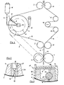
- a rotating application cylinder 4 is used to apply the cross-gluing 17, the circumference of which corresponds exactly to the predetermined distance between the cross-gluing 17. This applies when the application cylinder 4 has a single row of holes 7 through which the adhesive emerges under the action of centrifugal force. However, it is also possible for the application cylinder 4 to contain two or more such rows of bores 7 which are at the same distance from one another. spell the scope of the application cylinder 4 is a whole multiple of the distance between the cross-banding 17th
- the web 2 to be coated is guided with the aid of the deflection roller 3 in such a way that the application cylinder 4 is wrapped in the web 2 in a not inconsiderable part of its circumference. In the area of this wrapping, the row of holes 7 is accordingly covered by the web 2.
- the other web 14 is guided in the usual way over the guide rollers 15 and can be changed by means of the register roller 16 in such a way that a registration accuracy of certain points of the webs 2, 14 can be set. So that the peripheral speeds of the pull rollers 1 and the application cylinder 4 are constant, the application cylinder 4 is driven by the pull roller 1 via the gear 5 in connection with a correspondingly dimensioned driven wheel 6.
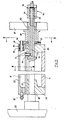
- the adhesive to be applied is located in a stationary collecting container 12 and arrives via the adhesive line 11 to a stationary adhesive connection 10, from where the adhesive is supplied to a radial connecting channel 9 via an axial bore 30 in the cylinder shaft 28 (see FIG. 4). which opens into an adhesive feed channel 8, from which the row of holes 7 extends.
- the centrifugal force of the adhesive is counteracted by various forces, one of the most important of which is the capillary force in the outlet openings of the row of holes 7.
- the outlet openings 18 are designed as simple bores with a diameter of approximately 0.8 mm without narrowing.
- the individual outlet opening 18 is designed as a throttle nozzle which, starting from the adhesive feed channel 8, has a bore constriction 20 which widens again into a bore outlet 19.
- the adhesive feed channel 8 is located in an exchangeable insert 21, which is inserted in a corresponding recess in the application cylinder 4 and is supplied with adhesive via the radial connecting channel 9. It has proven to be advantageous to design the bore outlet 19 to be approximately 1 mm long and with a diameter of approximately 0.8 mm, whereas the bore constriction 20 can be, for example, 2 mm to 4 mm long and a diameter of only approximately 0.3 mm having.
- the constriction 20 counteracts the centrifugal force of the adhesive located in the constriction 20 when the application cylinder 4 rotates.
- the throttle nozzle is covered on the outside by the web 2. This means that the adhesive can only bubble out slowly. Even if the outlet opening 18 is not covered by the web 2, the rotation of the up leads carrying cylinder 4 does not cause the adhesive to be thrown off. It is only advisable to cover the outlet openings 18 from the outside during longer breaks in work. For this reason, the covering device 13 is provided in FIG. When work is interrupted, the application cylinder 4 is uncoupled from its drive 5, 6 and brought into a position in which the row of holes 7 is opposite the cover device 13. It is sufficient to prevent air from entering the outlet openings 18 from the outside.
- the position of the cover device 13 can be changed due to the design. It can also be provided with a lifting or swiveling drive, not shown.
- the adhesive is preferably supplied from the collecting container 12 to the application cylinder 4 under pressure, so that if the cover 13 is disregarded, the adhesive could gradually exude.
- the application cylinder 4 is first brought back into its original position in order to bring about the registration accuracy of the cross-gluing 17 with respect to the position of the webs 2, 14.
- FIG. 3 being an enlarged partial cross section of the application container. ters 4 along the line III - III. in Figure 4.
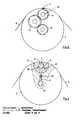
- the connecting channel 9 opens into an adhesive supply channel 8, which extends along a surface line of the application cylinder 4 and, in the example of FIG. 3, is formed by a hollow insert 21, the hollow strip 22 of which is closed on the inside by a cover 23.
- This arrangement 22, 23 is firmly inserted into a corresponding recess in the application cylinder 4, but is interchangeable.
- a control shaft 24 extending longitudinally therein is arranged and rotatable in the adhesive feed channel 8 stored. This carries on its periphery a closure element 25 in the form of a strip-shaped sealing lip which is set against the inside of the outlet openings 18. It is advisable to provide the control shaft 24 with an adjustable bearing so that the required sealing effect is brought about.
- the sealing lip (closure element) 25 can also be guided in a radially movable manner on the control shaft 24 and pressed on with springs. Between the control shaft 24 and the corresponding bore of the feed channel 8 there is a play 26 through which the adhesive can pass from the feed channel 8 to the outlet openings 18 when the closure element 25 has opened the outlet openings 18 by rotating the control shafts 24.
- a cylinder shaft 28 is rotatably supported in bearing plates 27 via bearings 52, which supports the jacket of the cylinder via flanges 29.
- the connecting channel 9 extends in the radial direction, which can be formed by a tube 41.
- the axial bore 30 opens into the fixed adhesive connection 10, specifically in its hollow shaft 53, which is mounted with the aid of the bearing 31 and is sealed via the seals 32.
- the hollow shaft 53 of the adhesive connection 10 is connected to the cylinder shaft 28.
- the screw connection 10 can easily be replaced by a screw connection, not shown.
- the adhesive feed channel 8 is provided with an outlet connection 35, which is actuated for cleaning or emptying the application cylinder 4 or the adhesive feed channel 8.
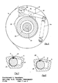
- a gear mechanism shown in FIG. 5 is provided for the oscillating control movement of the control shaft 24.
- On the control shaft 24 is a rocker arm 36, which is provided with a cam roller 39 and is loaded by a spring 40.
- This cam roller 39 rotates with the rocker arm 36 about the axis of the application cylinder 4 and rolls on a fixed cam 37.
- FIG. 4 shows that this cam plate 37 is connected in a fixed manner to the end shield 27 via a connecting sleeve 38.
- the cam disc 37 is designed so that the control shaft 24 is rotated to release the outlet openings 18 (see FIG. 3) as long as the row of holes 7 is covered by the web 2 surrounding the application cylinder 4.
- the application cylinder 4 is essentially hollow and, if necessary, stiffened in places by webs.
- control shaft executes an oscillating rotary movement to open or close the outlet openings 18.
- the control can also be brought about by a rotary movement of the control shaft 24.
- a gear 43 sits on the control shaft 24, which is connected via an idler gear 44 to a stationary drive pinion 45 and rolls on it.
- This drive pinion 45 can be connected to the end shield 27 in a manner similar to the cam disk 37. It is essential that the control shaft 24 executes one revolution with respect to the application cylinder 4 when the application cylinder 4 rotates. The direction of rotation of the control shaft 24 can can be chosen arbitrarily.
- the closure element 24 is then to be designed in such a way that the outlet openings 18 are only opened when the row of openings 7 is covered by the web 2.
- FIGS. 7 and 8 show the locking and opening position of the control shaft 24 with its closure element 25.
- adjustment mechanisms (not shown) can be provided on the adjusting drives of the control shaft 24.
- the intensity of the adhesive outlet from the outlet openings 18 can also be influenced by further measures which are generally referred to in the invention as metering arrangements.
- the functional relationship between centrifugal force and rotational speed of the application cylinder 4 can be influenced by exposing the adhesive to be supplied to a negative or positive pressure control. This can be done, for example, by changing the pressure conditions in the collecting container 12. Fig. 1 take place.
- a control is shown schematically, in which a valve 48 is present in the connecting channel 9, which prevents the flow of adhesive from the axial bore 30 to the adhesive supply channel 8.
- the adhesive feed channel 8 should only be partially filled. With 51 the adhesive reservoir is designated.
- the valve 48 is actuated so that a The adhesive flows into the feed channel 8. This can take place, for example, via a bypass line (not shown), the valve 48 being axially displaceable in the connecting channel 9.
- FIG. 9 shows only one way of constructively solving the problem described.
Landscapes
- Coating Apparatus (AREA)
- Application Of Or Painting With Fluid Materials (AREA)
- Treatment Of Fiber Materials (AREA)
Abstract
Description
- Die Erfindung bezieht sich auf ein Queranleimwerk für sehr schnell laufende Bahnen, insbesondere für die Verklebung mehrerer Bahnen in Rotationsdruckpressen. Unter dem Begriff "sehr schnell laufende Bahnen" werden solche mit einer stufenlos änderbaren Vorschubgeschwindigkeit von mehreren hundert Metern/Minute, beispielsweise 300 bis 500 m/min, verstanden.
- Die Erfindung geht von einer vorbekannten Anleimvorrichtung nach der DE-PS 11 15 120 aus, bei welcher der Klebstoff von einem Vorratsbehälter dem Innenraum eines rotierenden Auftragezylinders, an dessen Umfang die Bahn tangiert, zugeführt und durch in der Zylinderwandung befindliche Austrittsöffnungen auf die Bahn aufgetragen wird.
- Die Queranleimung schnell laufender Papierbahnen ist bis zur Ge- genwart ungelöst geblieben, obwohl hierfür ein erheblicher Bedarf der Druckindustrie vorliegt. Es ist dem Grunde nach bekannt, mehrseitige Druckerzeugnisse so zu binden, daß längs des Falzes Klebstoff auf die einzelne Bahn aufgebracht wird, der nach dem Falzen eine Verklebung benachbarter Seiten im Falzbereich herbeiführt. In der Praxis wurde dieses Problem durch Aufbringen längs der Vorschubrichtung der Bahn sich erstreckender endlich langer Klebstoffstreifen gelöst (Rationalisierung bei der Fatigstellung von Druckprodukten, Bindereport Nr. 3/82, Industrie-Verlag). Das Auftragen begrenzt langer Klebstoff streifen setzt eine komplizierte Steuerung der Auftragemechanik voraus. Wesentliche Steigerungen der Maschinengeschwindigkeiten sind nicht realisierbar.
- Aus druck- und falztechnischen Gründen ist es bei bestimmten Druckmaschinen, sogenannten halbbreiten Maschinen, nicht anders möglich, als den Klebstoffauftrag als Queranleimung auf die Bahn aufzubringen, wobei unter dem Begriff Bahn nicht nur eine endlose sondern auch eine endliche, z.B. ein Bogen, verstanden wird. Von solchen Queranleimungen wird aber verlangt, daß sie präzise im Falzbereich bei minimalem Klebstoffaufwand aufgetragen werden müssen und einen scharfen Konturenbereich in Form einer schmalen Linie besitzen sollen. Diese Bedingung war nicht erreichbar. Es ist zwar theoretisch möglich, eine rotierende Auftrageleiste mit einem Leimwerk zu verbinden, wobei die kiste den Klebstoff von einer umlaufenden, in ein Leimbecken eintauchenden Walze abnimmt und auf die Bahn überträgt. Ganz abgesehen davon, daß dadurch keine konturenscharfen Auftragobilder entstehen, scheitert die Anwendung dieses bekannten Prinzips an den geforderten hohen Bahngeschwindig- keiten, weil der Klebstoff aufgrund Fliehkraft schon bei kleineren Bahngeschwindigkeiten dazu neigt, von der Tauchwalze bzw. der Auftrageleiste wegzuspritzen.
- Die Auftragevorrichtung nach der eingangs erwähnten DE-AS 11 15 120 erwies sich in der Praxis nicht als erfolgversprechend, weil der Klebstoff schon nach kurzen Arbeitsunterbrechungen in den Austrittsöffnungen eintrocknet, diese unbrauchbar macht und somit kein korrektes Auftragebild erzielen läßt. Die Entwicklung der Auftragetechnik für Klebstoff ist seit dieser Erkenntnis auch andere Wege gegangen.
- Der Erfindung liegt die Aufgabe zugrunde, ein Queranleimwerk für sehr schnell laufende Bahnen oder Zuschnitte zu entwickeln, das in der Lage ist, unabhängig von den sich ändernden Geschwindigkeiten lage - und konturengenaue Beleimungen an vorgegebenen Stellen auf-zutragen, ohne daß die Gefahr des Wegspritzens des Klebstoffes besteht. Die erfindungsgemäße Lösung dieser Aufgabe besteht darin, daß die Bahn einen Teilbereich des Mantels des Auftrageszylinders umschlingt, dessen Umfang dem gewünschten Abstand der Querleimung oder einem ganzen Vielfachen dieses Abstandes entqricht, daß die Austrittsöffnungen als längs von Mantellinien des Auftragezylinders sich erstreckende Bohrungsreihen in Ein- oder Mehrzahl ausgebildet sind und daß sich an die Innenseite der einzelnen Austrittsöffnungen ein Klebstoffzuführkanal erstreckt, der mit einem ortsfesten axialen Klebstoffanschluß des Auftragezylinders in Verbindung steht.
- Vorzugsweise ist die einzelne Austrittsöffnung als Bohrung (Drosseldüse) solchen Durchmessers ausgebildet, daß die Zentrifugalkraft des Klebstoffes auch bei hohen Drehzahlen des Auftragezylinders nur geringfügig größer als die entgegenwirkenden Kräfte ist. Es hat sich als vorteilhaft erwiesen, wenn die Austrittsöffnung hinter einem etwa 1 mm langen Bohrungsauslauf von etwa 0,8 mm Durchmesser eine Bohrungsverengung von etwa 2 bis 4 mm Länge bei einem Durchmesser von etwa 0,3 mm besitzt.
- Mit der Erfindung wurde zunächst vermieden, den Klebstoff aus dem Hohlraum eines rotierenden Zylinders aufzutragen. Je größer nämlich die Füllmenge des Zylinders ist, desto größer ist die Oberfläche der Klebstoffmasse und desto leichter neigt der Klebstoff zur Hautbildung. Stattdessen ht der Zylinder beim Gegenstand der Erfindung mehr eine Tragefunktion. Der Klebstoff wird nämlich durch ein peripher des Auftragezylinders entlang einer Mantellinie sich erstreckenden Röhrchens (Klebstoffzuführkanal) an die als Bohrungen oder Drosseldüsen ausgebildeten Austrittsöffnungen herangeführt.
- Dadurch wird die in Rotation befindliche Masse wesentlich verringert, die Fließgeschwindigkeit des Klebstoffes erhöht und demgemäß die Hautbildung vermieden. Dessen ungeachtet beruht der Klebstoffauftrag auf der Fliehkraft des in den Austrittsöffnungen befindlichen Klebstoffes, welcher im wesentlichen die Viskosität, die Drosselwirkung (Kapillarwirkung) und der Außendruck entgegenwirken. Es kommt nun darauf an, die Querschnitte der Austrittsöffnungen so zu wählen, daß der Klebstoff selbst bei hohen Rotationsgeschwindigkeiten niht aus den Austrittsöffnungen ausspritzen kann. Da der Auftragezylinder in einem nicht unbeachtlichen Teil seines Umfanges von der zu beschichtenden Bahn umschlungen ist, wirkt die Bahn in diesem Bereich abdeckend und hindert den Klebstoff am Ausfließen. Es erfolgt lediglich eine Art Ausperlen des Klebstoffes aus den Austrittsöffnungen. Da die Umfangsgeschwindigkeit des Auftragezylinders genau der Vorschubgeschwindigkeit der zu beschichtenden
- Bahn entspricht, bilden sich an der Bahn punktförmige Auftragebilder, die zusammen eine Queranleimreihe ergeben. Sobald aber die Lochreihe der Austrittsöffnungen sich von der den Auftragezylinder teilweise umschlingenden Bahn entfernt, würde theoretisch die Möglichkeit des Ausspritzens des Klebstoffes aus den Austrittsöffnungen bestehen, bis die Lochreihe wieder von der Bahn überdeckt wird. Diese Strecke der unabgedeckten Bewegung der Lochreihe führt nach den Erfahrungen der praktischen Erprobung des Erfindungsgegenstandes jedoch nicht dazu, daß der Klebstoff abgeschleudert wird. Die Kapillarkräfte sind vielmehr so stark, daß sie lediglich ein Auffüllen der Austrittsöffnungen durch nachfließenden Klebstoff zulassen. Selbst dann, wenn ein nach der Erfindung ausgestalteter Auftragezylinder unabgedeckt einen gewissen Winkel rasch durchläuft, erfolgt kein Abschleudern des Klebstoffes. Es hat sich aber als vorteilhaft erwiesen, bei Stillstand des Auftragezylinders während einer Arbeitspause die Bohrungsreihe von außen her abzudecken, um das Eintrocknen des Klebstoffes zu verhindern. Aus diesem Grunde kann beispielsweise der Auftragezylinder von seinem Antrieb abgekuppelt und in eine Grundstellung bewegt werden, in der die Bohrungsreihe von außen her zugänglich ist. Bei Wiederbeginn der Arbeit muß der Auftragezylinder wieder in seine richtige Arbeitsposition gebracht und mit dem Antrieb eingekuppelt werden. Die Austrittsöffnungen können einzeln, gruppenweise oder insgesamt in einem mit dem Auftragezylinder austauschbar verbundenen Einsatz angeordnet sein.
- Es gibt nun im Sinne der Erfindung verschiedene Möglichkeiten, um die Steuerung des Klebstoffautrages zu verbessern und einen kontrollierten Einsatz des Queranleimwerkes für den Dauerbetrieb zu ermöglichen. Eine bevorzugte Lösung dieses Problemes besteht darin daß die Austrittsöffnungen innenseitig durch ein Verschlußelement gesteuert abdeckbar sind. Dieses Verschlußelement öffnet den Zugang zu den Kapillaröffnungen, sobald die Bohrungsreihe von der zu beschichtenden bahn Überdeckt ist. Demgemäß erfolgt das Verschließen rechtzeitig, bevor die Bahn den Mantelbereich des Auftragezylinders wieder verläßt. Zweckmäßigerweise durchsetzt das Verschlußelement den KlebstoffzufUhrkanal, und es wird oszillierend oder rotativ angetrieben.
- In einem Ausführungsbeispiel der Erfindung ist das Verschlußelement als eine leistenförmige, gegen die Innenseite der Austrittsöffnungen anstellbare Dichtlippe ausgebildet und radial vorstehend an einer den KlebstoffzufUhrkanal mit Spiel durchsetzenden und am Auftragezylinder drehbar gelagerten Steuerwelle angeordnet. Sowohl der Klebstoffzuführkanal als auch die Steuerwelle können erfindungsgemäß in einem Einsatz, beispielsweise in einer hohlen Leiste angeordnet sein, der in eine passende Ausnehmung des Auftragezylinders einsetzbar ist.
- Zur oszillierenden Steuerung der Steuerwelle bietet sich eine verhältnismäßig einfache Konstruktion an. Danach sitzt auf der Steuerwelle ein mit einer Rolle oder dgl. versehener Kipphebel, der also mit dem Auftragezylinder rotiert, dessen Rolle gegen eine konzentrisch zur Achse des Auftragezylinders angeordnete ortsfeste Kurvenscheibe federnd angestellt ist. Zweckmäßige Ausgestaltungen dieser Anordnung ergeben sich aus den Unteransprüchen 10 bis 12.
- Bei der rotativen Steuerung der Steuerwelle ist nach einem Ausführungsbeispiel der Erfindung die Steuerwelle mit einem Zahnrad versehen, das sich mittelbar oder unmittelbar an einem konzentrisch zur Achse des Auftragezylinders angeordneten ortsfesten Zahnrad abwälzt. Bei diesem nach Art eines Umlaufrädergetriebes funktionierenden Antrieb führt die Steuerwelle eine gleiche Umdrehung wie der Auftragezylinder aus, wobei sich die Steuerwelle auch gegensinnig zum Auftragezylinder drehen kann. Wesentlich ist dabei, daß das Verschlußelement so ausgebildet ist, daß in dem Bereich, wo die lochreihe von der zu beschichtenden Bahn abgedeckt ist, die Austrittsöffnungen mit dem Zuführkanal in Verbindung stehen und Klebstoff abgeben können.
- Bei umfangreichen Versuchen mit dem Erfindungsgegenstand konnte 5überraschenderweise festgestellt werden, daß die Durchflußmenge des Klebstoffes durch die Austrittsöffnungen überraschenderweise und in großen Bereichen in einem linearen Verhältnis zur Rotationsgeschwindigkeit des Auftragezylinders steht. Um aber dennoch Abweichungen von diesem linearen Verhältnis nicht negativ zur Aus-Owirkung kommen zu lassen, sieht die Erfindung im Rahmen einer weiteren Ausgestaltung vor, daß der Auftragezylinder mit einer drehzahl- oder verbrauchsabhängigen Dosieranordnung zur Veränderung der Füllmenge des Klebstoffzuführkanals versehen oder verbunden ist. Zur Gestaltung solcher Dosieranordnungen bieten sich erfindungsgemäß die verschiedensten Möglichkeiten an. So ist es beispielsweise möglich, die Dosieranordnung aus einem den Klebstoffzuführkanal von seiner Verbindung mit dem Klebstoffanschluß trennenden, insbesondere in einer radialen Verbindungsleitung angeordneten Ventil zu gestalten. Dieses Ventil hat die Wirkung, den im Klebstoffzuführkanal und in den Austrittsöffnungen befindlichen Klebstoff vorübergehend vor dem nachfließenden Klebstoff zu trennen, um auf diese Weise die Fliehkräfte zu reduzieren. Es empfiehlt sich in diesem Fall, im Bereiche des Zuführkanals Be- und Entlüftungsanordnungen vorzusehen, um das Ausfließen des Klebstoffes aus den Bohrungen zu erleichtern.
- Eine weitere Möglichkeit zur Gestaltung der Dosieranordnung besteht in der Anordnung einer Drossel im Zuführbereich des Klebstoffes, die auch um ihren Querschnitt drehzahlahhängig einstellbar sein kann.
- Schließlich sieht die Erfindung die Möglichkeit vor, als Dosieranordnung eine Unter- oder Uberdrucksteuerung für den in den Klebstoffzuführkanal zu fördernden Klebstoff vorzusehen. Im wesentlichen ist damit beabsichtigt, den durch die Fliehkraft entstehenden Druck in den Austrittsöffnungen nach den Gegebenheiten zu erhöhen oder zu senken. Es hat sich sogar herausgestellt, daß bei solchen Steuerungen das innenseitige Abdecken der Austrittsöffnungen entbehrlich ist. Andererseits kann bei dem innenseitigen Abdecken der Austrittsöffnungen auf eine Verengung dieser Austrittsöffnungen verzichtet werden.
- Einzelheiten der Erfindung ergeben sich aus der Zeichnung. In ihr ist die Erfindung schematisch und beispielsweise dargestellt. Es zeigen:
- Fig. 1: eine schematische Seitenansicht eines Queranleimwerkes für die Vergebung von zwei endlosen Bahnen und
- Fig. 2: einen Teilquerschnitt in vergrößerter Darstellung durch eine als Drosseldüse ausgebildete Austrittsöffnung,
- Fig. 3: einen Teilquerschnitt in vergrößerter Darstellung durch einen im Auftragezylinder angeordneten Klebstoffzuführkanal,
- Fig. 4: einen Längsschnitt durch einen Auftragezylinder,
- Fig. 5: einen Querschnitt durch den Auftragezylinder entlang der Linie V - V gemäß Fig. 4,
- Fig. 6: eine Stirnansicht eines Auftragezylinders mit einem rotativen Steuerantrieb,
- Fig. 7 und 8: Teilquerschnitte durch einen Klebstoffzuführkanal gemäß Fig. 3 in zwei verschiedenen Stellungen und
- Fig. 9: einen Querschnitt durch einen Auftragezylinder mit einer Ventilsteuerung.
- Im Ausführungsbeispiel der Figur 1 wird davon ausgegangen, daß zwei endlose Bahnen 2, 14 durch ein Zugwalzenpaar 1 zusammengeführt und gefördert werden, wobei das Problem besteht, an einer Bahn 2 in vorgegebenen Abständen Queranleimungen 17 anzubringen, die beim Zusammenführen beider Bahnen 2, 14 zu deren strichweisen Verleimung führen. Wenn im Bereiche dieser Queranleimungen 17 sich quer erstreckende Falze gebildet werden, ist es möglich, die Bahnen 2, 14 sowie weitere Bahnen zu mehrseitigen gebundenen Erzeugnissen, z.B. Zeitungen, Zeitschriften, Broschüren, Formularsätze und dgl. zu verarbeiten.
- Zum Aufbringen der Queranleimungen 17 wird ein rotierender Auftragezylinder 4 verwendet, dessen Umfang genau dem vorgegebenen Abstand zwischen den Queranleimungen 17 entspricht. Dies gilt dann, wenn der Auftragezylinder 4 eine einzige Bohrungsreihe 7 aufweist, durch welche der Klebstoff unter Fliehkraftwirkung austritt. Es ist aber auch möglich, daß der Auftragezylinder 4 zwei oder mehr solcher Bohrungsreihen 7 enthält, die zueinander in gleichem Abstand sich befinden. bann beträgt der Umfang des Auftragezylinders 4 ein ganzes vielfaches vom Abstand der Queranleimungen 17.
- Die zu beschichtende Bahn 2 wird mit Hilfe der Umlenkwalze 3 so geführt, daß der Auftragezylinder 4 in einem nicht unerheblichen Teil seines Umfanges von der Bahn 2 umschlungen ist. Im Bereiche dieser Umschlingung ist demgemäß die Lochreihe 7 von der Bahn 2 abgedeckt. Die andere Bahn 14 wird in üblicher Weise über die Führungswalzen 15 geführt und ist mittels der Registerwalze 16 so veränderbar, daß eine Deckungsgenauigkeit bestimmter Stellen der Bahnen 2, 14 eingestellt werden kann. Damit die Umfangsgeschwindigkeiten der Zugwalzen 1 und des Auftragezylinders 4 konstant sind, wird der Auftragezylinder 4 von der Zugwalze 1 über das Getriebe 5 in Verbindung mit einem entsprechend bemessenen Abtriebsrad 6 angetrieben.
- Der aufzutragende Klebstoff befindet sich in einem ortsfesten Sammelbehälter 12 und gelangt über die Klebstoffleitung 11 zu einem ortsfesten Klebstoffanschluß 10, von wo aus der Klebstoff über eine axiale Bohrung 30 in der Zylinderwelle 28 (vgl. Fig. 4) einem radialen Verbindungskanal 9 zugeführt wird, der in einen Klebstoffzuführkanal 8 mündet, von dem aus die Bohrungsreihe 7 ausgeht.
- Der Fliehkraft des Klebstoffes wirken verschiedene Kräfte entgegen, von denen eine der wichtigsten die Kapillarkraft in den Austrittsöffnungen der Bohrungsreihe 7 ist. Im Falle der Fig. 1 und 3 sind die Austrittsöffnungen 18 als einfache Bohrungen mit einem Durchmesser von etwa 0,8 mm ohne Verengung ausgebildet.
- Beim Ausführungsbeispiel der Fig. 2 ist die einzelne Austrittsöffnung 18 als Drosseldüse ausgebildet, welche, vom Klebstoffzuführkanal 8 ausgehend, eine Bohrungsverengung 20 aufweist, die sich wieder in einen Bohrungsauslauf 19 erweitert. Der Klebstoffzufuhrkanal 8 befindet sich in einem auswechselbaren Einsatz 21, der in einer entsprechenden Aussparung des Auftragezylinders 4 eingesetzt ist und über den radialen Verbindungskanal 9 mit Klebstoff versorgt wird. Es hat sich als vorteilhaft erwiesen, den Bohrungsauslauf 19 etwa 1 mm lang und mit einem Durchmesser von etwa 0,8 mm zu gestalten, wohingegen die Bohrungsverengung 20 beispielsweise 2 mm bis 4 mm lang sein kann und einen Durchmesser von nur etwa 0,3 mm aufweist. Die Verengung 20 wirkt der Fliehkraft des in der Verengung 20 befindlichen Klebstoffes bei Rotation des Auftragezylinders 4 entgegen. Außerdem ist die Drosseldüse außenseitig von der Bahn 2 abgedeckt. Dies führt dazu, daß der Klebstoff nur langsam ausperlen kann. Selbst dann, wenn die Austrittsöffnung 18 nicht von der Bahn 2 abgedeckt ist, führt die Rotation des Auftragezylinders 4 nicht zu einem Abschleudern des Klebstoffes. Lediglich bei längeren Arbeitsunterbrechungen empfiehlt es sich, die Austrittsöffnungen 18 von außen her abzudecken. Aus diesem Grunde ist in Figur 1 dia Abdeckvorrichtung 13 vorgesehen. Bei Arbeitsunterbrechung wird der Auftragezylinder 4 von seinem Antrieb 5, 6 abgekuppelt und in eine Lage gebracht, bei der die Bohrungsreihe 7 der Abdeckvorrichtung 13 gegenüberliegt. Es genügt, den Luftzutritt an die Austrittsöffnungen 18 von außen her zu verhindern.
- Die Lage der Abdeckvorrichtung 13 kann konstruktionsbedingt geändert werden. Sie kann auch mit einem nicht dargestellten Hub- bzw. Schwenkantrieb versehen sein. Bevorzugt wird der Klebstoff aus dem Sammelbehälter 12 unter Druck dem Auftragezylinder 4 zugeführt, so daß bei Außerachtlassung der Abdeckung 13 nach und nach ein Ausschwitzen des Klebstoffes stattfinden könnte. Bei Beginn der Klebearbeit wird zunächst der Auftragezylinder 4 wieder in seine ursprüngliche Stellung gebracht, um die Passergenauigkeit der Querverleimung 17 zur Lage der Bahnen 2, 14 herbeizuführen.
- Im Ausführungsbeispiel der Figuren 3 bis 5 ist nun eine Ausführungsform des erfindungsgemäßen Queranleimwerkes dargestellt, wobei die Figur 3 ein vergrößerter Teilquerschnitt des Auftragebehäl. ters 4 entlang der Linie III - III.in Figur 4 ist.
- Danach mündet der Verbindungskanal 9 in einen Klebstoffzuführkanal 8, der sich entlang einer Mantellinie des Auftragezylinders 4 erstreckt und beim Beispiel der Figur 3 von einem hohlen Einsatz 21 gebildet ist, dessen hohle Leiste 22 innenseitig von einem Deckel 23 abgeschlossen ist. Diese Anordnung 22, 23 ist in eine entsprechende Aussparung des Auftragezylinders 4 fest eingesetzt, aber austauschbar. In dem Klebstoffzuführkanal 8 ist eine sich darin längs erstreckende Steuerwelle 24 angeordnet und drehbar gelagert. Diese trägt an ihrem Umfang ein Verschlußelement 25 in Form einer leistenförmigen Dichtlippe, welche gegen die Innenseite der Austrittsöffnungen 18 angestellt ist. Es empfiehlt sich, die Steuerwelle 24 mit einer einstellbaren Lagerung zu versehen, damit die erforderliche Abdichtwirkung herbeigeführt wird. Die Dichtlippe (Verschlußelement) 25 kann auch an der Steuerwelle 24 radial beweglich geführt und mit Federn angedrückt sein. Zwischen der Steuerwelle 24 und der entsprechenden Bohrung des Zuführkanals 8 befindet sich ein Spiel 26, durch welches der Klebstoff aus dem Zuführkanal 8 bis an die Austrittsöffnungen 18 gelangen kann,wenn das Verschlußelement 25 die Austrittsöffnungen 18 durch Verdrehen der Steuerwellen 24 freigegeben hat.
- Im Ausführungsbeispiel der Figur 4 ist der konstruktive Aufbau des Auftragezylinders 4 gezeigt. Danach ist in Lagerschilden 27 über Lager 52 eine Zylinderwelle 28 drehbar gelagert, die über Flansche 29 den Mantel des Zylinders trägt. In der Zylinderwelle 28 befindet sich eine axiale Bohrung 30, von der aus der Verbindungskanal 9 in radialer Richtung ausgeht, der durch ein Rohr 41 gebildet sein kann. Die axiale Bohrung 30 mündet in den ortsfesten Klebstoffanschluß 10 und zwar in dessen Hohlwelle 53, die mit Hilfe des Lagers 31 gelagert und über die Dichtungen 32 abgedichtet ist. Die Hohlwelle 53 des Klebstoffanschlusses 10 ist mit der Zylinderwelle 28 verbunden. Durch eine nicht gezeigte Verschraubung kann 5der Klebstoffanschluß 10 leicht ausgewechselt werden.
- In einem Teilausschnitt der Fig. 4 erkennt man die Lagerung der Steuerwelle 24 mit Hilfe der Dichtung 34 und der Lager 33. Der Klebstoffzuführkanal 8 ist mit einem Auslaßstutzen 35 versehen, 50der zum Reinigen oder Entleeren des Auftragezylinders 4 bzw. des Klebstoffzuführkanals 8 betätigt wird.
- Zur oszillierenden Steuerbewegung der Steuerwelle 24 ist ein in Figur 5 gezeigtes Getriebe vorgesehen. Auf der Steuerwelle 24 sitzt ein Kipphebel 36, der mit einer Kurvenrolle 39 versehen und von einer Feder 40 belastet ist. Diese Kurvenrolle 39 rotiert mit dem Kipphebel 36 um die Achse des Auftragezylinders 4 und rollt dabei an einer ortsfesten Kurvenscheibe 37 ab. In Figur 4 ist gezeigt, daß diese Kurvenscheibe 37 über eine Verbindungshülse 38 ortsfest mit dem Lagerschild 27 in Verbindung steht. Die Kurvenscheibe 37 ist so gestaltet, daß die Steuerwelle 24 zwecks Freigabe der Austrittsöffnungen 18 (vgl. Figur 3) verdreht wird, solange die Bohrungsreihe 7 von der den Auftragezylinder 4 umgebenden Bahn 2 abgedeckt ist.
- Hierbei kann statt des vorstehenden Nockens der Kurvenscheibe auch eine entsprechende Vertiefung vorgesehen sein, wodruch eine Sperrung der Austrittsöffnungen 18 leichter möglich ist. Um die rotierende Masse gering zu halten, ist der Auftragezylinder 4 im wesentlichen hohl ausgebildet und ggf. stellenweise durch Stege versteift.
- In dem besagten Ausführungsbeispiel der Figuren 3 bis 5 führt die Steuerwelle zum Öffnen oder Schließen der Austrittsöffnungen 18 also eine oszillierende Drehbewegung aus.
- Gem. Fig. 6 kann die St-euerung aber auch eine rotative Bewegung der Steuerwelle 24 herbeigeführt werden. Zu diesem Zweck sitzt auf der Steuerwelle 24 ein Zahnrad 43, welches über ein Zwischenrad 44 mit einem ortsfesten Antriebsritzel 45 in Verbindung steht und sich daran abwälzt. Dieses Antriebsritzel 45 kann auf die ähnliche Weise wie die Kurvenscheibe 37 mit dem Lagerschild 27 verbunden werden. Wesentlich ist, daß die Steuerwelle 24 bei einer Umdrehung des Auftragezylinders 4 eine Umdrehung in bezug zum Auftragezylinder 4 ausführt. Die Drehrichtung der Steuerwelle 24 kann beliebig gewählt werden. Das Verschlußelement 24 ist dann so zu gestalten, daß die Austrittsöffnungen 18 nur dann freigegeben werden, wenn die Bphrungsreihe 7 von der Bahn 2 abgedeckt ist.
- In den Figuren 7 und 8 ist die Sperr- und Öffnungsstellung der Steuerwelle 24 mit ihrem Verschlußelement 25 gezeigt. Man kann durch Veränderung des Drehwinkels der Steuerwelle 24 den Öffnungsgrad an den Austrittsöffnungen 18 der Bohrungsreihe 7 verringern oder erweitern und dadurch eine Drosselung der Durchflußmenge erreichen. Zu diesem Zweck können an den Verstellgetrieben der Steuerwelle 24 nicht dargestellte Einstellmechaniken vorhanden sein.
- Die Intensität des Klebstoffaustrittes aus den Austrittsöffnungen 18 kann auch noch durch weitere Maßnahmen beeinflußt werden, die in der Erfindung generell als Dosieranordnungen bezeichnet sind. Man kann beispielsweise den funktionellen Zusammenhang von Fliehkraft und Rotationsgeschwindigkeit des Auftragezylinders 4 damit beeinflussen, daß man den zuzuführenden Klebstoff einer Unter- oder Uberdrucksteuerung aussetzt. Dies kann beispielsweise durch Veränderung der Druckverhältnisse im Sammelbehälter 12 gem. Fig. 1 erfolgen. Man kann aber auch drucktechnisch auf den in der Klebstoffleitung 11 oder in der axialen Bohrung 30 befindlichen Klebstoff drehzahlabhängig einwirken.
- )Im Ausführungsbeispiel der Figur 9 ist eine Steuerung schematisch gezeigt, bei der in dem Verbindungskanal 9 ein Ventil 48 vorhanden ist, welches den Klebstoffluß von der axialen Bohrung 30 zum Klebstoffzuführkanal 8 unterbindet. Dadurch kann der Füllstand des Klebstoffzuführkanals 8 geregelt werden. Der Klebstoffzuführkanal 8 )soll nur teilweise gefüllt sein. Mit 51 ist das Klebstoffreservoir bezeichnet. Beispielsweise in Abhängigkeit vom Füllstand des Klebstoffzuführkanals 8 wird das Ventil 48 so betätigt, daß ein Nachfließen des Klebstoffes in den Zuführkanal 8 ermöglicht wird. Dies kann beispielsweise über eine nicht dargestellte Bypass-Leitung erfolgen, wobei das Ventil 48 im Verbindungskanal 9 axial verschieblich ist.
- Durch diese teilweise Füllung des Klebstoffzuführkanals 8 und der damit verbundenen Trennung vom Druck des nachfließenden Klebstoffes werden die Fliehkräfte und damit auch der Ausfluß von Klebstoff erheblich reduziert. Um dennoch einen ausreichenden Klebstoffauftrag zu ermöglichen, sind die Ventile 49, 50 für das Ablassen und Aussaugen von Luft vorgesehen. Bei Bedarf kann auch noch eine Druckluftüberlagerung im Klebstoffzuführkanal 8 für gleichmäßigeren Klebstoffauftrag über den ganzen Geschwindigkeitsbereich sorgen. Da es zahlreiche andere Möglichkeiten zur Drucksteuerung gibt, sei mit der Figur 9 nur ein Weg zur konstruktiven Lösung des geschilderten Problems aufgezeigt.
-
- 1 Zugwalzenpaar
- 2 Bahn
- 3 Umlenkwalze
- 4 Auftragezylinder
- 5 Getriebe
- 6 Abtriebsrad
- 7 Bohrungsreihe
- 8 Klebstoffzuführkanal
- 9 Verbindungskanal
- 10 Klebstoffanschluß
- 11 Klebstoffleitung
- 12 Sammelbehälter
- 13 Abdeckvorrichtung
- 14 Bahn
- 15 Führungswalze
- 16 Registerwalze
- 17 Queranleimung
- 18 Austrittsöffnung
- 19 Bohrungsauslauf
- 20 Bohrungsverengung
- 21 Einsatz
- 22 Hohle Leiste
- 23 Deckel
- 24 Steuerwelle
- 25 Verschlußelement
- 26 Spiel
- 27 Lagerschild
- 28 Zylinderwelle
- 29 Zylinderflansch
- 30 axiale Bohrung
- 31 Lager
- 32 Dichtung
- 33 Lager
- 34 Dichtung
- 35 Auslaßstutzen
- 36 Kipphebel
- 37 ortsfeste Kurvenscheibe
- 38 Verbindungshülse
- 39 Kurvenrolle
- 40 Feder
- 41 Rohr
- 42
- 43 Zahnrad
- 44 Zwischenrad
- 45 ortsfestes Antriebsritzel
- 46 Abflachung
- 47 Kanalwand
- 48 Ventil
- 49 Luftablaßventil
- 50 Luftansaugventil
- 51 Klebstoff
- 52 Lager
- 53 Hohlwelle
- 54
- 55
- 56
Claims (17)
Applications Claiming Priority (2)
| Application Number | Priority Date | Filing Date | Title |
|---|---|---|---|
| DE3222335 | 1982-06-14 | ||
| DE3222335A DE3222335C2 (de) | 1982-06-14 | 1982-06-14 | Vorrichtung zum Auftragen eines Klebstoffes in Form einer Queranleimung auf eine Bahn |
Publications (3)
| Publication Number | Publication Date |
|---|---|
| EP0096832A2 true EP0096832A2 (de) | 1983-12-28 |
| EP0096832A3 EP0096832A3 (en) | 1984-11-07 |
| EP0096832B1 EP0096832B1 (de) | 1986-09-10 |
Family
ID=6166039
Family Applications (1)
| Application Number | Title | Priority Date | Filing Date |
|---|---|---|---|
| EP83105590A Expired EP0096832B1 (de) | 1982-06-14 | 1983-06-07 | Queranleimwerk für sehr schnell laufende Bahnen |
Country Status (7)
| Country | Link |
|---|---|
| US (1) | US4502912A (de) |
| EP (1) | EP0096832B1 (de) |
| JP (1) | JPS5959264A (de) |
| CA (1) | CA1196493A (de) |
| DD (1) | DD209981A5 (de) |
| DE (2) | DE3222335C2 (de) |
| ES (1) | ES523202A0 (de) |
Cited By (10)
| Publication number | Priority date | Publication date | Assignee | Title |
|---|---|---|---|---|
| EP0369348A3 (de) * | 1988-11-15 | 1991-01-23 | Baldwin-Gegenheimer GmbH | Vorrichtung zum Aufbringen eines Leimstreifens |
| EP0336358A3 (de) * | 1988-04-04 | 1991-07-03 | Somar Corporation | Vorrichtung zum Verbinden von dünnen Filmen |
| EP0477769A3 (en) * | 1990-09-25 | 1992-08-05 | Albert-Frankenthal Ag | Transverse glueing device for the application of glue on a moving web |
| DE29502723U1 (de) * | 1995-02-18 | 1996-06-20 | Planatol Klebetechnik GmbH, 83101 Rohrdorf | Behandlungsvorrichtung, insbesondere Querleimwerk |
| US5647949A (en) * | 1992-08-11 | 1997-07-15 | Albert-Frankenthal Aktiengesellschaft | Folder for web-fed printing presses |
| DE29712377U1 (de) * | 1997-07-12 | 1998-06-10 | Planatol Klebetechnik GmbH, 83101 Rohrdorf | Querleimwerk für laufende Bahnen |
| EP0880999A3 (de) * | 1997-05-27 | 1998-12-16 | Martin Christian Oepen | Vorrichtung und Verfahren zur Querbeleimung von Druckprodukten |
| US8753737B2 (en) | 2009-05-19 | 2014-06-17 | The Procter & Gamble Company | Multi-ply fibrous structures and methods for making same |
| US9243368B2 (en) | 2009-05-19 | 2016-01-26 | The Procter & Gamble Company | Embossed fibrous structures and methods for making same |
| EP3680024A1 (de) * | 2014-07-03 | 2020-07-15 | FRAUNHOFER-GESELLSCHAFT zur Förderung der angewandten Forschung e.V. | Modul zum auftragen eines viskosen mediums auf eine oberfläche und verfahren zum herstellen des moduls |
Families Citing this family (12)
| Publication number | Priority date | Publication date | Assignee | Title |
|---|---|---|---|---|
| DE3525805A1 (de) * | 1985-07-19 | 1987-01-29 | Hesselmann Planatolwerk H | Vorrichtung zum auftragen eines klebstoffes in form einer queranleimung |
| DE3527660A1 (de) * | 1985-08-01 | 1987-02-12 | Hesselmann Planatolwerk H | Verfahren und vorrichtung zur herstellung mehrseitiger, gefalzter und verklebter blattlagen |
| JPH069672B2 (ja) * | 1985-10-18 | 1994-02-09 | 富士写真フイルム株式会社 | 磁性液塗布方法 |
| US4724170A (en) * | 1986-09-02 | 1988-02-09 | The Goodyear Tire & Rubber Company | Apparatus and method for applying cement to an end portion of a flexible strip |
| JPH0390671U (de) * | 1989-12-27 | 1991-09-17 | ||
| JPH0671201U (ja) * | 1991-01-31 | 1994-10-04 | 株式会社マツショウ | トラック用ホイールキャップ |
| US5328544A (en) * | 1993-04-21 | 1994-07-12 | James River Paper Companey, Inc. | System for applying adhesive to sheet material |
| DE19720982B4 (de) * | 1997-05-20 | 2009-08-13 | Hhs Leimauftrags-Systeme Gmbh | Vorrichtung zum Auftragen von Leim |
| US20100028621A1 (en) * | 2008-08-04 | 2010-02-04 | Thomas Timothy Byrne | Embossed fibrous structures and methods for making same |
| US20100030174A1 (en) * | 2008-08-04 | 2010-02-04 | Buschur Patrick J | Multi-ply fibrous structures and processes for making same |
| US20100297378A1 (en) * | 2009-05-19 | 2010-11-25 | Andre Mellin | Patterned fibrous structures and methods for making same |
| US20100297395A1 (en) * | 2009-05-19 | 2010-11-25 | Andre Mellin | Fibrous structures comprising design elements and methods for making same |
Family Cites Families (12)
| Publication number | Priority date | Publication date | Assignee | Title |
|---|---|---|---|---|
| DE1037251B (de) * | 1954-01-16 | 1958-08-21 | Willy Hesselmann | Vorrichtung zur Erzeugung duenner Belaege, vornehmlich aus Klebstoff, auf Bahnen von Papier, Pappe, Stoffen od. dgl. |
| DE1115120B (de) * | 1957-02-21 | 1961-10-12 | Willy Hesselmann | Vorrichtung zum Antragen von fluessigen Stoffen, vornehmlich Klebstoff |
| DE1047968B (de) * | 1957-06-08 | 1958-12-31 | Beiersdorf & Co Ag P | Verfahren und Vorrichtung zur Herstellung von flaechenmaessig begrenzten Klebstoffaufstrichen |
| DE1097349B (de) * | 1959-07-16 | 1961-01-12 | Kronseder Hermann | Beleimvorrichtung fuer schnell laufende Etikettiermaschinen |
| US3332580A (en) * | 1965-09-20 | 1967-07-25 | Lockwood Tech | Fluid applicator valve |
| US3507650A (en) * | 1966-01-11 | 1970-04-21 | Polaroid Corp | Method of depositing viscous photographic reagents |
| DE1561492A1 (de) * | 1967-01-10 | 1970-02-12 | Erhard Klug | Vorrichtung zum Auftragen von Leimpunkten auf laufende Materialbahnen |
| DE1561523A1 (de) * | 1967-12-22 | 1970-05-27 | Windmoeller & Hoelscher | Vorrichtung zum Auftragen von Klebstoff auf Werkstoffbahnen |
| DE2305889C3 (de) * | 1973-02-07 | 1981-02-26 | Bischof Und Klein Gmbh & Co, 4540 Lengerich | Vorrichtung zum insbesondere formatmäßigen Auftragen eines flüssigen oder pastösen Klebstoffs auf ein flaches Werkstück |
| JPS5048929A (de) * | 1973-05-23 | 1975-05-01 | ||
| US4068618A (en) * | 1976-01-29 | 1978-01-17 | Trufuse International Ltd. | Apparatus for making material with fusible backing |
| JPS5513148A (en) * | 1978-07-15 | 1980-01-30 | Matsushita Electric Works Ltd | Hot melt adhesive coating machine |
-
1982
- 1982-06-14 DE DE3222335A patent/DE3222335C2/de not_active Expired
-
1983
- 1983-06-07 DE DE8383105590T patent/DE3366037D1/de not_active Expired
- 1983-06-07 EP EP83105590A patent/EP0096832B1/de not_active Expired
- 1983-06-10 US US06/503,315 patent/US4502912A/en not_active Expired - Lifetime
- 1983-06-13 ES ES523202A patent/ES523202A0/es active Granted
- 1983-06-13 CA CA000430240A patent/CA1196493A/en not_active Expired
- 1983-06-14 DD DD83252008A patent/DD209981A5/de not_active IP Right Cessation
- 1983-06-14 JP JP58105102A patent/JPS5959264A/ja active Granted
Cited By (13)
| Publication number | Priority date | Publication date | Assignee | Title |
|---|---|---|---|---|
| EP0336358A3 (de) * | 1988-04-04 | 1991-07-03 | Somar Corporation | Vorrichtung zum Verbinden von dünnen Filmen |
| EP0369348A3 (de) * | 1988-11-15 | 1991-01-23 | Baldwin-Gegenheimer GmbH | Vorrichtung zum Aufbringen eines Leimstreifens |
| EP0477769A3 (en) * | 1990-09-25 | 1992-08-05 | Albert-Frankenthal Ag | Transverse glueing device for the application of glue on a moving web |
| US5647949A (en) * | 1992-08-11 | 1997-07-15 | Albert-Frankenthal Aktiengesellschaft | Folder for web-fed printing presses |
| DE29502723U1 (de) * | 1995-02-18 | 1996-06-20 | Planatol Klebetechnik GmbH, 83101 Rohrdorf | Behandlungsvorrichtung, insbesondere Querleimwerk |
| US5876784A (en) * | 1995-02-18 | 1999-03-02 | Planatol Klebetechnik Gmbh | Treatment device, particularly for a transverse sizing machine |
| EP0880999A3 (de) * | 1997-05-27 | 1998-12-16 | Martin Christian Oepen | Vorrichtung und Verfahren zur Querbeleimung von Druckprodukten |
| DE29712377U1 (de) * | 1997-07-12 | 1998-06-10 | Planatol Klebetechnik GmbH, 83101 Rohrdorf | Querleimwerk für laufende Bahnen |
| US8753737B2 (en) | 2009-05-19 | 2014-06-17 | The Procter & Gamble Company | Multi-ply fibrous structures and methods for making same |
| US9243368B2 (en) | 2009-05-19 | 2016-01-26 | The Procter & Gamble Company | Embossed fibrous structures and methods for making same |
| US9701101B2 (en) | 2009-05-19 | 2017-07-11 | The Procter & Gamble Company | Multi-ply fibrous structures and methods for making same |
| US9937694B2 (en) | 2009-05-19 | 2018-04-10 | The Procter & Gamble Company | Method for making multi-ply fibrous structures |
| EP3680024A1 (de) * | 2014-07-03 | 2020-07-15 | FRAUNHOFER-GESELLSCHAFT zur Förderung der angewandten Forschung e.V. | Modul zum auftragen eines viskosen mediums auf eine oberfläche und verfahren zum herstellen des moduls |
Also Published As
| Publication number | Publication date |
|---|---|
| ES8403334A1 (es) | 1984-03-16 |
| DE3222335A1 (de) | 1983-12-15 |
| DD209981A5 (de) | 1984-05-30 |
| CA1196493A (en) | 1985-11-12 |
| DE3366037D1 (en) | 1986-10-16 |
| US4502912A (en) | 1985-03-05 |
| ES523202A0 (es) | 1984-03-16 |
| EP0096832A3 (en) | 1984-11-07 |
| JPS5959264A (ja) | 1984-04-05 |
| DE3222335C2 (de) | 1985-01-03 |
| JPH0575599B2 (de) | 1993-10-20 |
| EP0096832B1 (de) | 1986-09-10 |
Similar Documents
| Publication | Publication Date | Title |
|---|---|---|
| EP0096832B1 (de) | Queranleimwerk für sehr schnell laufende Bahnen | |
| DE1652402A1 (de) | Verfahren und Vorrichtung zum Beschichten von Baendern | |
| DE102004058542A1 (de) | Rotationsauftragskopf und Etikettieranlage zum Aufbringen von Etiketten | |
| DE3102139A1 (de) | "druckpresse zum bedrucken von blaettern, insbesondere aus wellpappe" | |
| DE2611262A1 (de) | Vorrichtung zur verteilung eines druckmittels und einer waschfluessigkeit an einer druckerpresse | |
| DE2105297A1 (de) | Einrichtung zum Imprägnieren von in Längsrichtung vorbewegtem Wellkarton | |
| EP3024588A1 (de) | Vorrichtung zum herstellen von packungen für zigaretten mit ventilanordnung | |
| EP1864801A1 (de) | Druckwerk einer Druckmaschine | |
| EP0901839B1 (de) | Vorrichtung zum Auftragen von Flüssigkeiten auf ein Substrat | |
| DE102007015401B4 (de) | Feuchtwerk für ein Druckwerk einer Druckmaschine | |
| EP1644195A2 (de) | Walze eines farb- oder feuchtwerkes | |
| DE4143003A1 (de) | Vorrichtung zum querfalten von bahnen oder bahnabschnitten aus papier, tissue, nonwoven oder dergleichen | |
| DE1954316A1 (de) | Verfahren und Einrichtung zum Beschicken von Walzen in Druckwerken von Druckmaschinen mit einem fluessigen Medium,z.B. Farbe,und zum Dosieren des Mediums | |
| DE3823179C1 (de) | ||
| DE68912289T2 (de) | Papierbeschichtung. | |
| DE2132850A1 (de) | Rotationsoffsetdruckmaschineneinheit | |
| DE2365668C3 (de) | Vorrichtung zur Verarbeitung bahnförmigen Materials mit einem Rotationsdruckwerk | |
| DE10322320B4 (de) | Ventilanordnung für Sprühfeuchtwerke von Druckmaschinen | |
| DE102007015404B4 (de) | Feuchtwerk für ein Druckwerk einer Druckmaschine | |
| DE2442478A1 (de) | Vorrichtung zum aufbringen von leim fuer eine vielbahnige papierzufuehrmaschine | |
| DE3005920C2 (de) | ||
| DE593016C (de) | Vorrichtung zum Auftragen einer elastischen Schicht aus plastischer Masse auf die Einzelscheiben von nicht splitternden Glaesern | |
| DE324319C (de) | Vorrichtung zum einseitigen UEberziehen von Gewebebahnen mit zaehfluessiger Masse zur Herstellung von Wachstuchen, Kunstleder u. dgl. | |
| DE767019C (de) | Vorrichtung zur Farbfuehrung fuer Rotationsschablonendrucker | |
| DE2045344A1 (de) | Vorrichtung zum Auftragen von Leim |
Legal Events
| Date | Code | Title | Description |
|---|---|---|---|
| PUAI | Public reference made under article 153(3) epc to a published international application that has entered the european phase |
Free format text: ORIGINAL CODE: 0009012 |
|
| AK | Designated contracting states |
Designated state(s): BE CH DE FR GB IT LI NL SE |
|
| PUAL | Search report despatched |
Free format text: ORIGINAL CODE: 0009013 |
|
| AK | Designated contracting states |
Designated state(s): BE CH DE FR GB IT LI NL SE |
|
| 17P | Request for examination filed |
Effective date: 19841129 |
|
| GRAA | (expected) grant |
Free format text: ORIGINAL CODE: 0009210 |
|
| AK | Designated contracting states |
Kind code of ref document: B1 Designated state(s): BE CH DE FR GB IT LI NL SE |
|
| REF | Corresponds to: |
Ref document number: 3366037 Country of ref document: DE Date of ref document: 19861016 |
|
| ET | Fr: translation filed | ||
| ITF | It: translation for a ep patent filed | ||
| PLBE | No opposition filed within time limit |
Free format text: ORIGINAL CODE: 0009261 |
|
| STAA | Information on the status of an ep patent application or granted ep patent |
Free format text: STATUS: NO OPPOSITION FILED WITHIN TIME LIMIT |
|
| 26N | No opposition filed | ||
| ITTA | It: last paid annual fee | ||
| EAL | Se: european patent in force in sweden |
Ref document number: 83105590.0 |
|
| PGFP | Annual fee paid to national office [announced via postgrant information from national office to epo] |
Ref country code: GB Payment date: 20000522 Year of fee payment: 18 |
|
| PGFP | Annual fee paid to national office [announced via postgrant information from national office to epo] |
Ref country code: FR Payment date: 20000616 Year of fee payment: 18 |
|
| PGFP | Annual fee paid to national office [announced via postgrant information from national office to epo] |
Ref country code: NL Payment date: 20000620 Year of fee payment: 18 |
|
| PGFP | Annual fee paid to national office [announced via postgrant information from national office to epo] |
Ref country code: CH Payment date: 20000623 Year of fee payment: 18 Ref country code: BE Payment date: 20000623 Year of fee payment: 18 |
|
| PGFP | Annual fee paid to national office [announced via postgrant information from national office to epo] |
Ref country code: SE Payment date: 20000626 Year of fee payment: 18 |
|
| PG25 | Lapsed in a contracting state [announced via postgrant information from national office to epo] |
Ref country code: GB Free format text: LAPSE BECAUSE OF NON-PAYMENT OF DUE FEES Effective date: 20010607 |
|
| PG25 | Lapsed in a contracting state [announced via postgrant information from national office to epo] |
Ref country code: SE Free format text: LAPSE BECAUSE OF NON-PAYMENT OF DUE FEES Effective date: 20010608 |
|
| PG25 | Lapsed in a contracting state [announced via postgrant information from national office to epo] |
Ref country code: LI Free format text: LAPSE BECAUSE OF NON-PAYMENT OF DUE FEES Effective date: 20010630 Ref country code: CH Free format text: LAPSE BECAUSE OF NON-PAYMENT OF DUE FEES Effective date: 20010630 Ref country code: BE Free format text: LAPSE BECAUSE OF NON-PAYMENT OF DUE FEES Effective date: 20010630 |
|
| BERE | Be: lapsed |
Owner name: PLANATOLWERK WILLY HESSELMANN CHEMISCHE UND MASCH Effective date: 20010630 |
|
| PG25 | Lapsed in a contracting state [announced via postgrant information from national office to epo] |
Ref country code: NL Free format text: LAPSE BECAUSE OF NON-PAYMENT OF DUE FEES Effective date: 20020101 |
|
| GBPC | Gb: european patent ceased through non-payment of renewal fee |
Effective date: 20010607 |
|
| EUG | Se: european patent has lapsed |
Ref document number: 83105590.0 |
|
| REG | Reference to a national code |
Ref country code: CH Ref legal event code: PL |
|
| PG25 | Lapsed in a contracting state [announced via postgrant information from national office to epo] |
Ref country code: FR Free format text: LAPSE BECAUSE OF NON-PAYMENT OF DUE FEES Effective date: 20020228 |
|
| NLV4 | Nl: lapsed or anulled due to non-payment of the annual fee |
Effective date: 20020101 |
|
| PGFP | Annual fee paid to national office [announced via postgrant information from national office to epo] |
Ref country code: DE Payment date: 20020621 Year of fee payment: 20 |